

Larzep HAM5524 Operating And Maintenance Instructions Manual
1
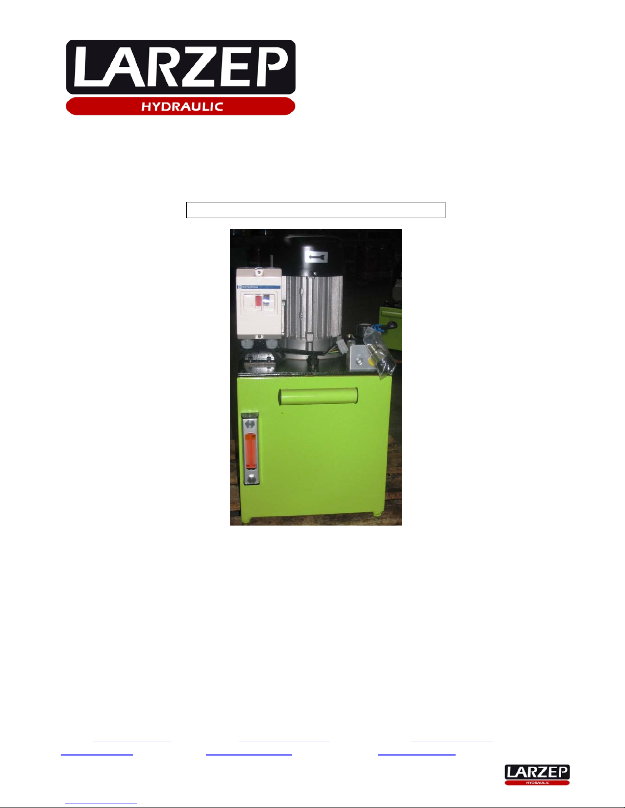
OPERATING AND MAINTENANCE INSTRUCTIONS
HYDRAULIC ELECTRICAL PUMPS
HAM (Manual control)
Part Nr : HA M 5 5 2 4
1. Essential safety requirements.
2. Technical Characteristics.
3. Installation and start up.
4. Maintenance.
5. Problems, malfunctions and solutions.
6. Declaration of conformity.
• APPENDIX 1 – General diagram.
• APPENDIX 2 – Hydraulic diagram.
• APPENDIX 3 – Electrical diagram.
LARZEP,S.A. LARZEPAUSTRALIAPTY.LTD. LARZEPGBLTD.
AvenidaUrtiaga,6 104WedgewoodRoad, 3CommerceWay‐LeightonBuzzard
48269MALLABIA,SPAIN HALLAM,VIC.3803AUSTRALIA BEDSLU74RWUNITEDKINGDOM
Tel.+34943171200 Tel.+61(3)97963744 Tel.+441525377819
Fax.+34943174166 Fax.+61
(3)97965964 Fax.+441525851990
e‐mail:sales@larzep.com
e‐mail:sales@larzep.com.au e‐mail:sales@larzep.co.uk
www.larzep.com
www.larzep.com.au www.larzep.co.uk
2
1. ESSENTIAL SAFETY REQUIREMENTS
1.1 GENERAL CONSIDERATIONS.
LARZEP hydraulic electrical pumps have been specially designed and manufactured in accordance with our quality
standards and the controls demanded by the ISO 9001 standard. Nevertheless, improper use ma y result in the death or
serious injury of the user and third parties, as well as causing grave damage to the machine and related materials.
¾ In light of the above, it is important that the machine s hould only be used under perfect technical condi tions and in accordance
with the considerations outlined in this manual. The operator should be aware of the risks inherent in the use of high-pressure
hydraulic appliances, familiar with the working of the machine and capa ble of giving the relevant orders to the personnel working
in the area.
¾ The machine is designed exclusively for the applications described in this manual. The manufacturer accepts no
responsibility for damage resulting from any other application or improper use.
1.2 ORGANISATIONAL PRINCIPLES
¾ The operator should h ave access to the instructions at all times.
¾ As a complementary precaution, in addition to the instructions manual, the operator should be instructed in the use of the
machine and the rules and regulations covering this type of operation, such as those relating to accident prevention and
environmental protection, for example.
¾ All personnel working with the machine must use personal protection equipment:
Boots, Helmets Goggles Gloves and Protective clothing.
¾ With the aim of avoiding personal injury or material damage, the operator should receive practical training in the use of the
machine, and be aware of and apply the necessary safety measures.
¾ Each time the machine is used; all personnel should foll ow the instructions outlined in the ‘Start up’ section of this instructions
manual.
¾ Never modify the equipment or add elements that affect its safety without the manufacturer’s express authorisation.
¾ Repairs and maintenance operations, etc. should only be carried out by specialist personnel. Al ways use original Larzep spare
parts.
¾ Replace the flexible hydraulic hoses on a regular basis, even if they show no signs of wear or damage.
¾ Maintenance o perations should be carried out on a regular basis in accordance with the instructions outlined in this manual.
¾ Once you have finished using the machine, disconnect it, clean it and store it in a clean, safe place.
1.3 GENERAL SAFETY INSTRUCTIONS
¾ If you notice that the machine or one of the installation’s elements is not working properly, stop the operation in process
immediately, block the load and then correct the problem.
¾ Before switching the machine on, make sure that no one is located in the danger zone.
¾ Check that the machine and its accessories have not been damaged during transportation and installation.
¾ Use the equipment in a well-light area.
¾ All the material in the installation should be securely installed and thoroughly stable, and the operator fully aware of all the
movements to be carried out during the application.
You should calculate a maximum use of 80% of the machine’s nominal capacity.
Do not work under the load. If this is absolutely unavoidable, first block the load mechanically.
¾ Locate the load points in areas of maximum stability, and distribute the load uniformly.
Do not expose equipment to intense heat sources, such as welding, for example.
Eliminate pressure and disconnect the machine before carrying out maintenance operations.
¾ Never, under any circumstances, exceed the machine’s nominal capacity. Use indicators to monitor the operating pressure.
¾ Controls should be used with your hands. Do not use tools or levers, etc. for this purpose. When using tools (to regulate the
external limiting valve, for example), make sure you select the correct one and do not use excessive force.
¾ Clean the machine after use and store in a safe place where there is no risk of damage or dirt.
¾ Make sure that the plugs and accessor ies in gen eral ar e kept perfectl y clean. Dirt y plugs are difficult to connect and ma y res ult in
dirt entering the hydraulic circuit.
¾ Make sure that the flexible hy draulic hoses are not twisted or flattened by loads.
¾ Make sure that the remote pendant is not activated and that the electro valve is in its standby or neutral position (centre open).
When using manual valves, ensure that they are set to position ‘C’ (centre) before initiating the operation .
¾ Never trust the load to the pump valves alone. Use safety valves when you wish to stabilise the cylinder pressure, and if
possible, block the load mechanically.
3
2. TECHNICAL FEATURES
Part Nr : HA M 5 5 2 4 0 0 0 0
2.1 ELECTRIC PUMP WITH MANUAL VALVE
-
Useful oil capacity:........................ 25 lit.
- Oil flow at 700 bar: ........................ 2,2 l/min
- Motor: .......................................... Electric
-
Power: ....................................... 3 Kw
- Voltage: ....................................... 400 V. 50/60 Hz. 3 ph.
-
Valve ways/Positions: .................. Manual
3/3 Single acting Advance/Hold/Retract
- Options:
Remote pendant (for HAM)........... NO
External protective frame ............. NO
Set of wheels ............................... NO
Oil cooler ..................................... NO
2.2 DESCRIPTION.
The electrical pump consists of the following principal parts:
• Up to 14 litters, aluminium tank with oil level and transport handle.
• From 25 litters on, metal tank with oil level and transport handles.
• 100 litters, metal tank with oil level and eye bolts.
• Up to 14 litters, aluminium lid, support for the entire hydraulic circuit.
• From 25 litters on, metal lid, support for the entire hydraulic circuit.
• Electric motor with corresponding coupling.
• Hydraulic piston pump with filter.
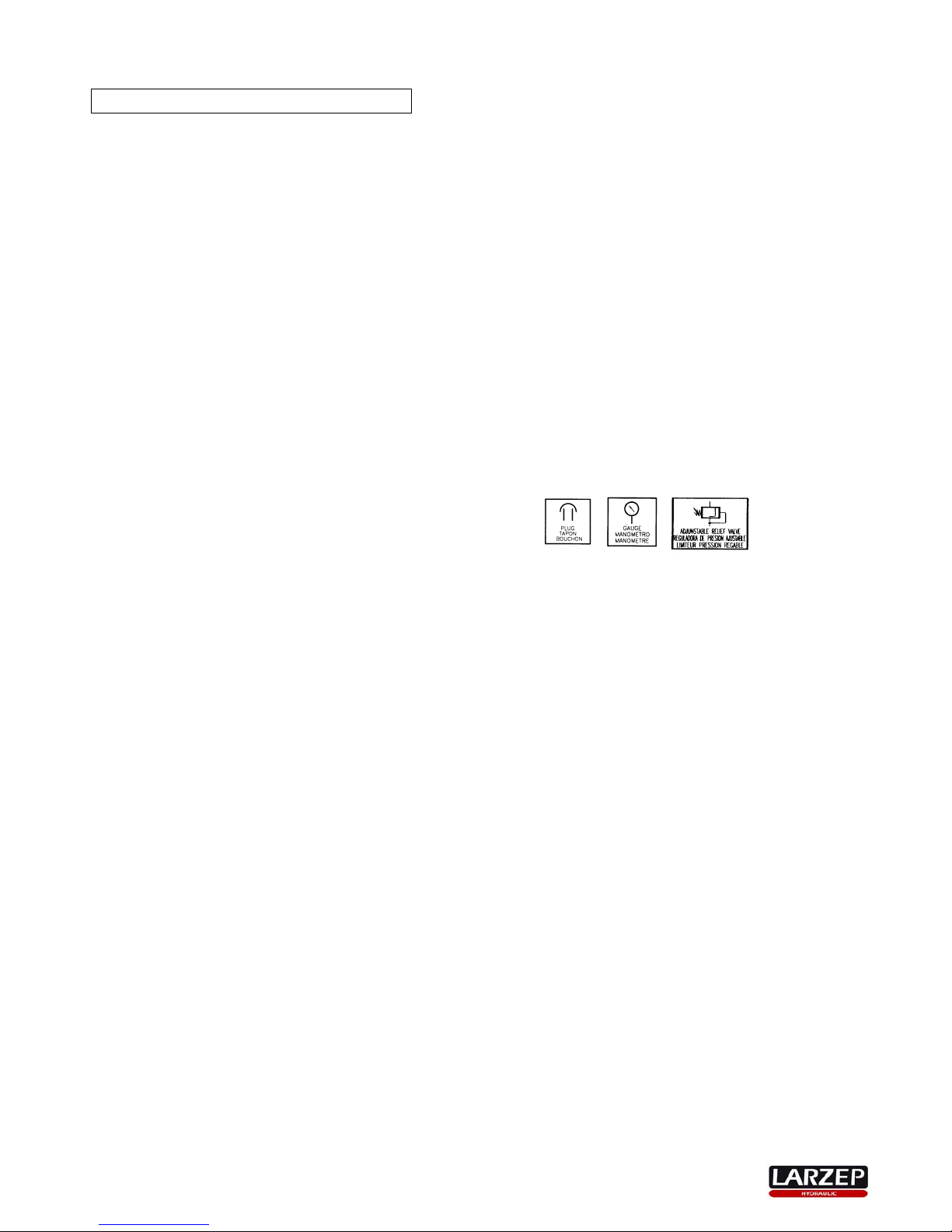
• Transportation plug and ventilation plug (plastic bag), except from 100 litters tank models.
• Pressure meter connection, except from 2,5 and 5 litters tank models.
• Electrical cabinet or motor circuit breaker box.
• Manual distributing valve or electro valve with 3/8 NPT outputs.
• Internal safety valve adjusted to 700 bar .
• Adjustable external pressure regulating valve: 0-700 bar.
3. INSTALLATION AND START UP
3.1 INSTALLATION
¾ Read the instructions manual thoroughly and apply the contents.
¾ Make sure that the machine h as not been damaged during transportation and is both clean and complete.
¾ Position the machine is a stable, well-protected area.
¾ Use hoses that are long enough to make sure the operator is well away from the danger zone.
¾ Assemble the complete installation making sure that all accessories (hoses, quick-plugs, valves, joints, pressure meters,
distributors, cylinders, etc.) are properly connected. Check without a load as indicated in the next point. A good inst allation is
essential to the proper, risk-free functioning of the machine, and should therefore be carried out by qualified personnel only.
¾ Connecting the hoses. Operation of the distributing valve:
¾ Two-position manual control. Single effect cylinder. Type: HAM _ _ 1 _.
o The distributing valve has a single outlet for connection to the hose.
o When the lever is set to position ‘P’ (towards the hose outlet), the cylinder moves out.
o Turning the lever to position ‘T’ (opposite direction), causes the cylinder to return, thanks to the action of the spri ng
or the weight of the load itself.
¾ Three-position manu al control. Single effect cylinder. Type: HAM _ _ 2 _.
o Connect the hose to outlet ‘A’ (plastic plug). Do not use the connection point marked with an ‘X’. This p oint should
remain plugged.
o When the lever is set to position ‘A’, the cylinder moves forward. When the lever is in position ‘C’, it maintains the
load in its current position. And when the lever is set to ‘T’, the cylinder returns, thanks to the action of the spring or
the weight of the load itself.

4
¾ Three-position manu al control. Double effect cylinder. Type: HAM _ _ 4 _.
o Connect the cylinder’s forward hose (pressure) to outlet ‘A’ of the d istributing valve, and the return hose to outlet
‘B’.
o When the lever is set to position ‘A’, the cylinder m oves forward. When the lever is in position ‘C’, it maintains the
load in its current position, and when the lever is set to ‘B’, the cylinder returns, thanks to the pressure applied by
the oil distributed by the pump.
¾ Two-position el ectrical control. Single effect cylinder. Type: HAE _ _ 1 _.
o The distributing valve has a single outlet for connection to the hose.
o When the UP button of the remote pendant is pressed, the cylinder moves for ward. When the button is released, it
moves back, thanks to the action of the spring or the weight of the load itself.
¾ Three-position electrical control. Single effect cylinder. Type: HAE _ _ 2 _.
o Connect the hose to outlet ‘A’ (plastic plug). W hen the ‘UP’ button on the remote pendant is pressed, t he cylinder
moves forward. When it is released, the cylinder maintain s the pressure level and the load remains where it is.
When the ‘DOWN’ button is pressed, the cylinder returns thanks to the action of the spring or the weight of the load
itself.
¾ Three-position electrical control. Double effect cylinder. Type: HAE _ _ 4 _.
o Connect the cylinder’s forward hose (pressur e) to outlet ‘A’ (upper) of the distributing valve, and the ret urn hose to
outlet ‘A’ (lower). When the ‘UP’ button on the remote pendant is pressed, the cylinder moves forward. When it is
released, the cylinder maintains the pressure level a nd the load remains where it is. When the ‘DOWN’ button is
pressed, the cylinder returns thanks to the pressure applied by the oil distributed by the pump.
¾ Make sure that the voltage level in the mains coincides with that specified for the machine.
3.2 CHECKING THE CORRECT FUNCTIONING OF ALL MACHINE PARTS
¾ Replace the tr an sportation plug with the ventilation plug (supplied in a plastic bag).
¾ Check the tank level.
¾ Connect the mains electricity supply to the terminal strip in the electrical cabinet.
¾ Make sure that the remote penda nt is deactivated and that the manual control is set to either ‘C’ or ‘T’.
¾ With HAE-type electrical control pumps, rotate the electric al cabinet’s side s witch to position ‘1’. A green pil ot light will come on.
Press the electrical cabinet’s green button to start the motor.
¾ Check that the direction of rotation coincides with that indicated by the arro w on the electric motor lid. If the directions do not
coincide, stop the motor (by pressing the red switch), set the side switch to ‘0’ and swap the two cables around in the terminal.
Repeat the operation and check that the direction of rotation is now correct.
¾ With HAM-type manual control pumps, pr ess the black button on the circ uit break er box t o start the motor. Check the direction of
rotation as explained in the previous point.
¾ With electrical control pumps, when the ‘UP’ button on the remote pendant is pressed, the cylinder p iston moves forward once
the hose has filled with oil. The piston moves back when the ‘DOWN’ button is pressed.
¾ Practise moving the piston back and forth.
¾ With manual control pum ps, whe n the l ever is set to pos ition ‘A’ or ‘P’, the c ylinder piston moves for ward onc e the h ose has f illed
with oil. The piston moves back when the lever is set to position ‘B’ or ‘T’.
¾ After making sure that no one is located in the danger zone, carefully extend the cylinder as far as it will go.
VERY IMPORTANT:
BEFORE DOING THIS, MAKE SURE THAT THE CYLINDER OR HYDRAULIC TOOL IS DESIGNED TO WITHSTAND
ALL THE PRESSURE AT THE END OF ITS STROKE.
¾ The point of the pressure gauge is only subjected to press ure when the remote pendant is activated or the manual control is se t
to position ‘A’ or ‘B’.
¾ Use a pressure gauge at this point to check that the internal safety valve is set correctly to 700 bar.
¾ If you wish to check the pressure of an installation without pressing the remote pendant (open centre, ‘P’ connecte d to ‘T’ and
forward and back movements blocked) or with the manual control set to ‘C’, you should place the pressure gauge and its
corresponding joint in the output of the distributing valve.
¾ If you do not press the remote pendant or the manual valv e control is set to ‘C’, the distrib uting valve’s check valv es will maintain
the pressure in the circuit.
¾ If the proposed operating pressure is less than 700 bar, use the external pressure regulator.
¾ Use a spanner to loosen the lock nut and a screwdriver to loosen (anticlockwise – reduces pressure) or tighten (c lockwise –
increases pressure) the adjustment screw. Use a pressure gauge to check that the desired operating pressure has been
reached, and then block the adjustment screw using the lock nut to prevent unwanted loosening due to vibrations.
¾ Check for leaks when working under pressure and make sure that the machine and the installation are working correctly in
accordance with the established application.
¾ The above steps should be repeated as man y times as necessary, until the op erator has become fami liar with the working of the
machine.
ALL THESE CHECKS SHOULD BE CARRIED OUT WITHOUT A LOAD. THEIR AIM IS TO ENABLE OPERATORS T O BECOME
FAMILIAR WITH THE WORKING OF THE MACHINE.
In HAE-type pumps with electrical control, check the correct working of the emergenc y stop mechanism: the RED EMERGENCY
BUTTON in the remote pendant.
 Loading...