

Page 1
EPS-2XPB-SG-DPMS
Larson Electronics, LLC Phone: (800) 369-6671 Fax: (903) 498-3364 www.larsonelectronics.com
1 of 2
EPS-2XPB-SG-DPMS OPERATION MANUAL
IMPORTANT: This enclosure and device must be installed by trained, qualified and competent personnel. Installation
Explosion Proof Double Push Button Switch
READ THIS SHEET CAREFULLY BEFORE BEGINNING INSTALLATION.
must comply with local, state and national regulations, as well as safety practices for this type of equipment.
WARNING: Electrical power must be OFF during installation, or performing any maintenance. Disconnect primary power
source and lock out.
CAUTION: Before installing, make sure you are compliant with area classifications, failure to do so may result in bodily
injury, death and property damage. Do not attempt installation until you are familiar with the following procedures. All
installation must comply with the applicable Electrical Code. Make sure that the circuit is De-energized before starting
installation or maintenance. Verify that the installation is grounded. Failure to ground will create electrical shock hazards,
which can cause serious injury and or death. Important: Please read these instructions carefully before installing or
maintaining this equipment. Good electrical practices should be followed at all times and this data should be used as a
guide only.
ENCLOSURE MOUN
If you have received fully assembled enclosure with factory installed devices, just follow the instructions and warnings
below for installing and wiring the enclosure.
The moun
contained devices.
Securely fasten the en
an approved electrical conducting type lubricant on the threads. The conduit thread connections must be tapered pipe
thread conforming to ANSI B1.20.1. A minimum of (5) full threads engagement is required for all conduit connections.
Conduit sealing fittings must be installed within 18 inches of the enclosure. Sealing fittings must be approved for the
specific hazardous location where the enclosure is used. All unused conduit openings must be plugged using close-up
plugs. Plugs must be tightly installed with a minimum engagement of (5) full threads.
▲ Inspect and clean the machined flange flame joint surfaces of both the cover and the box. Surfaces must be smo
free of nicks, scratches, dirt or any foreign particle build-up that would prevent a proper seal. Surfaces must seat fully
against each other to provide a proper explosion-proof joint. Clean surfaces by wiping with a clean, lint-free cloth.
ting location must be flat and provide proper clearance, rigidity and strength to support the enclosure and all
TING INSTALLATION:
closure to the mounting location. Install sealing fittings, cable glands, unions and/or conduit, using
oth,
Apply a ligh
supplied with the enclosure. Check the bolted joint with a .0015 thick feeler gauge. The gauge must not enter the joint
more than 1/8” at any point. NOTE: Loose bolts or an improper joint can result in an explosion, creating a potential for
personal injury and property damage.
NOTE: If installing a brea
they are to be used. Some drains/breathers may not comply with Nema 3 & 4 standards. Also, provide a protective
covering to shield the breather and drain during hose-down operations.
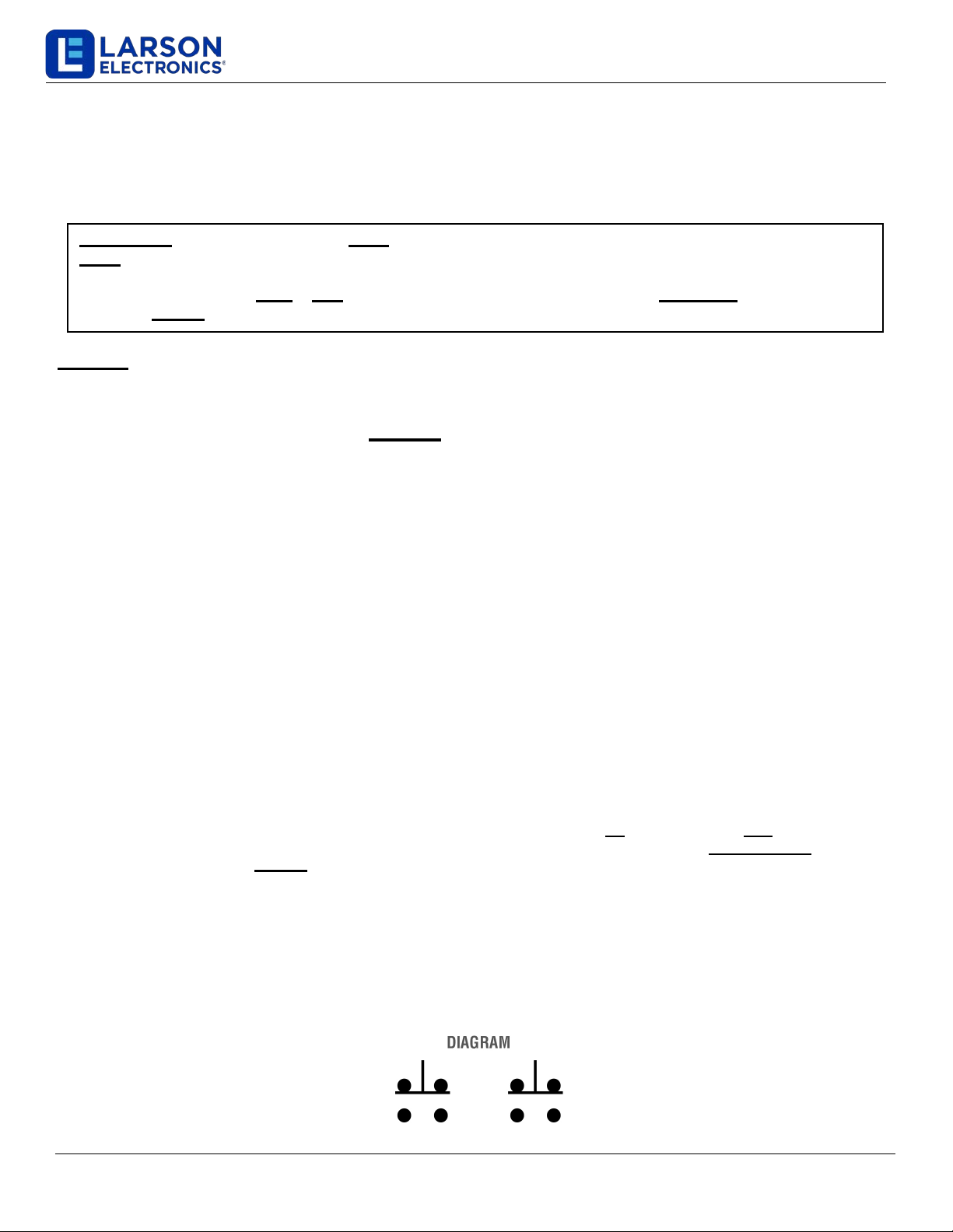
Wire according to the diagrams on the switches. The factory installed pushbuttons in cover is set up to interface with
the switches, once the cover was installed on the box.
t coating of lubricant to flange surfaces and close the cover. Tighten all cover bolts. Use only those bolts
ther and/or a drain, make certain they are suitable for the specific hazardous location where
Page 2

EPS-2XPB-SG-DPMS
Larson Electronics, LLC Phone: (800) 369-6671 Fax: (903) 498-3364 www.larsonelectronics.com
2 of 2
MAINTENANCE DATA
WARNING: Before servicing the enclosure, be sure the electrical power is OFF. Disconnect the enclosure from
the primary power source and lock-out.
After installation, this enclosure should be inspected at regular intervals. A visual inspection should ascertain that all
cover bolts are still tight; that all conduit connections are intact and free of corrosion, and that the enclosure mounting
bolts are tight and in good condition.
If the enclosure must be opened for servicing, to check or replace internal devices and apparatus, the following
procedures should be followed:
Loosen cover bolts. Replace any corr
oded, bent or otherwise damaged bolts with new, factory authorized bolts obtained
from an authorized Larson Electronics distributor. Open enclosure. Do not use hammer, screwdriver or any prying tool to
open cover.
ct machined, flame joint flange surfaces. Surfaces must be smooth, free of nicks, scratches, dirt or any foreign
Inspe
particle build-up that would prevent a proper seal. Should surface be damaged, contact factory. Never attempt to rework
surfaces by sanding, grinding, etc. Surfaces must seat fully against each other to provide a proper explosion-proof joint.
Inspe
ct water exclusion gasket. If gasket is damaged, do not attempt field replacement or repair. Contact a factory
authorized representative for a replacement cover. The damaged gasket can be removed from the cover, and the cover
without gasket can be used until a replacement is obtained. The cover, without gasket, can be safely used in Class I & II
hazardous (classified) locations, however, the enclosure may not be rain-tight or hose-down resistant. Follow Installation
Instructions at ▲ on Page 1.
 Loading...