

Page 1

Larson Davis
Spartan Model 730
Noise Dosimeter
Reference Manual
730 Dosimeter Reference Manual
Page 2
Copyright
Copyright 2019, by PCB Piezotronics, Inc. This manual is copyrighted, with all rights reserved. The manual may not be copied
in whole or in part for any use without prior written consent of PCB Piezotronics, Inc.
Disclaimer
The following paragraph does not apply in any state or country where such statements are not agreeable with local law:
Even though PCB Piezotronics, Inc. has reviewed its documentation, PCB Piezotronics Inc. makes no warranty or representation, either expressed or implied, with respect to this instrument and documentation, its quality, performance, merchantability, or fitness for a particular purpose. This documentation is subject to change without notice, and should not be construed as
a commitment or representation by PCB Piezotronics, Inc.
This publication may contain inaccuracies or typographical errors. PCB Piezotronics, Inc. will periodically update the material
for inclusion in new editions. Changes and improvements to the information described in this manual may be made at any
time.
Safety
If the equipment is used in a manner not specified by Larson Davis, the protection provided by the equipment may be
impaired.
Recycling
PCB Piezotronics, Inc. is an environmentally friendly organization and encourages our customers to be environmentally conscious. When this product reaches its end of life, please recycle the product through a local recycling center. Alternatively, you
may also ship the product to:
PCB Piezotronics, Inc.
Attn: Recycling Coordinator
1681 West 820 North
Provo, Utah, USA 84601-1341
Warranty
For warranty information, refer to the Terms and Conditions of Sale section at
www.larsondavis.com/TermsConditions.aspx
Contact Larson Davis
Website
www.larsondavis.com
Worldwide Corporate Headquarters
Larson Davis - a PCB Piezotronics division
3425 Walden Avenue
Depew, NY 14043-2495 USA
Toll-free (in the US): 888-258-3222
Phone: 716-926-8243
USA fax: 716-926-8215
E-mail: sales@larsondavis.com
730 Dosimeter Reference Manual
Page 3

Table of Contents
Section 1 Product Overview 1
1.1 Dosimeter Overview........................................................................................................ 7
Section 2 Getting Started 16
2.1 Installing G4 .................................................................................................................. 16
2.2 Installing LD Atlas App for Mobile Devices ................................................................... 17
2.3 Charging the Spartan 730............................................................................................. 17
2.4 Connecting to Your Dosimeter...................................................................................... 19
2.5 Calibrating Your Spartan Dosimeter ............................................................................. 22
2.6 Installing the Dosimeter On the Wearer........................................................................ 26
Section 3 Setting a Measurement Configuration 27
3.1 Overview ....................................................................................................................... 27
3.2 Setting a Measurement Configuration On the Dosimeter ............................................. 27
3.3 Setting a Custom Configuration .................................................................................... 29
3.4 Saving a Configuration to the Dosimeter in G4............................................................. 30
3.5 Saving a Configuration Setup File in G4....................................................................... 30
3.6 Importing a Configuration Setup File to a Dosimeter .................................................... 31
3.7 Default Dosimeter Settings ........................................................................................... 32
Section 4 Making a Measurement 33
4.1 Making a Measurement................................................................................................. 33
4.2 Best Practices for Measuring Noise Exposure.............................................................. 35
4.3 Installing the Dosimeter On the Wearer........................................................................ 39
Section 5 Working With Data Files in G4 40
5.1 Downloading Data Files in G4....................................................................................... 40
5.2 Merging Data Files in G4 .............................................................................................. 43
5.3 Data Page Overview ..................................................................................................... 43
5.4 Using the Octave Band Analysis Feature ..................................................................... 46
5.5 Utilizing the Time History Graph ................................................................................... 49
5.6 Meters Panel Overview................................................................................................. 50
5.7 Files Page Overview ..................................................................................................... 50
5.8 Updating the G4 LD Utility............................................................................................. 51
5.9 Upgrading Spartan 730 Firmware................................................................................. 51
Section 6 Dosimeter Settings Reference 53
6.1 Setting a Visual Alarm on the Spartan 730 ................................................................... 53
6.2 Setting Up a Measurement Timer ................................................................................. 57
6.3 Setting Event Sound Recording Options....................................................................... 61
6.4 Customizing Frequency Weight and Detector Settings................................................. 62
6.5 Customizing the Meter Options..................................................................................... 64
6.6 Setting Date and Time Manually On the Meter............................................................. 68
6.7 Customizing the Meter Preferences.............................................................................. 69
Appendix A Technical Specifications
Appendix B Glossary
Appendix C Compliance and Standards Reference
A-1
B-1
C-1
730 Dosimeter Reference Manual
Page 4

Section 1 Product Overview
1.0.1 Contents ................................................................................................................... 2
1.0.2 Serial Numbers ......................................................................................................... 5
1.0.3 Basic Operations ...................................................................................................... 5
1.0.4 Applications ............................................................................................................. 5
1.0.5 Hardware Features ..................................................................................................5
1.0.6 Performance Features ............................................................................................. 6
1.0.7 Available Options ..................................................................................................... 6
1.0.8 Accessories ............................................................................................................... 6
1.1 Dosimeter Overview ...................................................................................... 7
1.1.1 Buttons ..................................................................................................................... 7
1.1.2 Navigating On the LCD Color Display ...................................................................... 8
1.1.3 Status Bar ................................................................................................................. 9
1.1.4 Screen Details On the Spartan 730 Dosimeter .....................................................10
1.1.5 Battery .................................................................................................................... 14
1.1.6 Charger and Alarm Status LEDs ............................................................................ 15
1.1.7 Care and Cleaning .................................................................................................. 15
Larson Davis Spartan 730 Dosimeter
The Larson Davis Spartan 730 dosimeter is a personal noise
measuring and recording device for an individual who may be
exposed to noise at work. The following high-tech, easy-to-use
capabilities make the Spartan the best choice for your project:
730 Dosimeter Reference Manual 1
Page 5
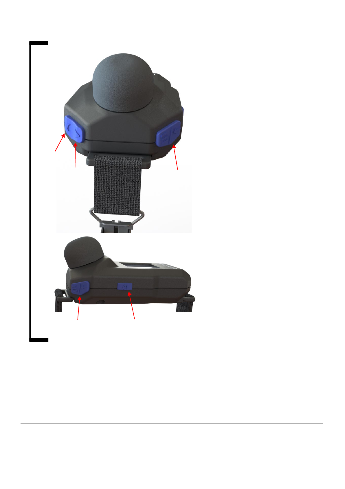
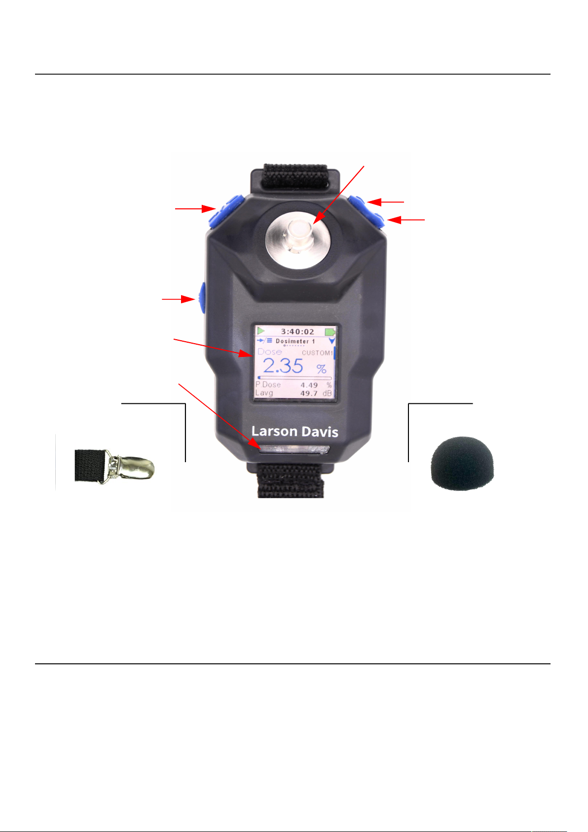
FIGURE Spartan 730 Dosimeter Buttons
Down
Up
Select (Menu)
• Monitor noise exposure data in realtime, remotely from the included LD
mobile app or the G4 LD Utility.
• Auto-calibrate your dosimeter simply
by attaching the included calibrator.
• Measure noise exposure using your
chosen configuration and up to 3
additional virtual dosimeter
configurations at once.
• Customize any standard
configuration (Dose, ISO) to meet your
specific needs.
• Use the G4 LD Utility’s custom
reporting features to easily generate
and share a single-page report with
your logo.
• Auto-download data files wirelessly
simply by bringing the dosimeter
within Bluetooth range, or by
connecting to your PC with the
included USB cable.
LEARN MOREThe Spartan dosimeter
meets or exceeds all applicable
international standards. For
compliance details, see
Compliance and Resources for
International Standards
Technical Specifications.
, and
• Set dosimeter timers to
automatically begin monitoring noise
exposure during specific periods of a
work shift.
• Set Action Level, and Limit Level
alarms to provide real-time exposure
feedback.
• Use the Octave Band Analysis (OBA)
capability to examine specific noise
exposure frequencies in full octaves.
Power Select (Menu)
The Spartan 730 dosimeter is built to last. Engineered and
manufactured using stringent processes and the highest quality
materials, we proudly stand proudly behind this product and our
commitment to “Total Customer Satisfaction.”
1.0.1 Contents
TAKE NOTE Report any damage or
shortage immediately. See
Larson Davis
730 Dosimeter Reference Manual Rev B 2
.
Contact
The Spartan 730 is shipped in protective packaging, or in the hard shell
Charging Case if purchased. Verify that your package contains the items
listed for your case configuration.
Page 6
TAKE NOTE For a full listing of all
C
E
D
AAA
B
B
B
configurations and accessories,
navigate to www.LarsonDavis.com.
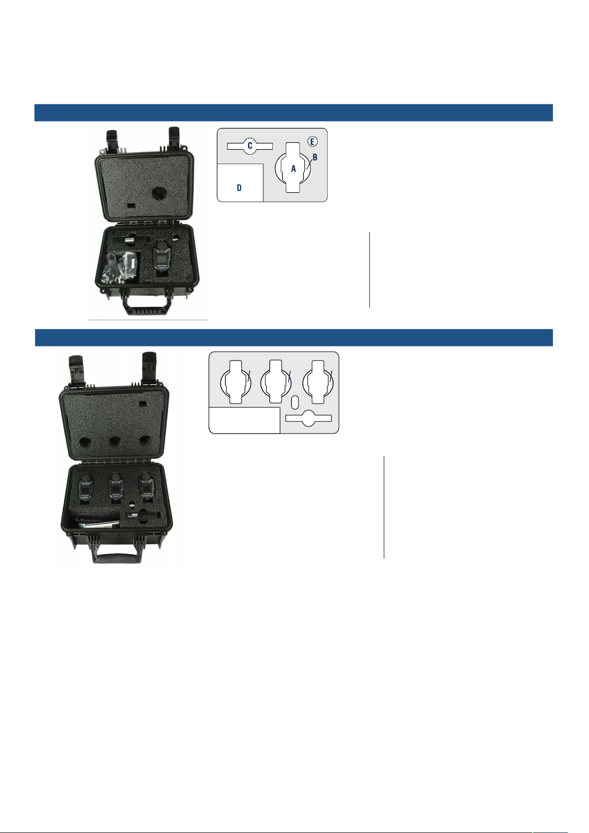
1-Pack With Charging Case
We recommend that you retain the packaging to safely ship your
dosimeter.
A. Model 730 Dosimeter (730) with windscreen
and clothing clips
B. Qi® wireless charging pad (PSA042)
C. Calibrator (CAL150) with 1/4” adapter
D. LD USB drive
E. Cables & Accessories include:
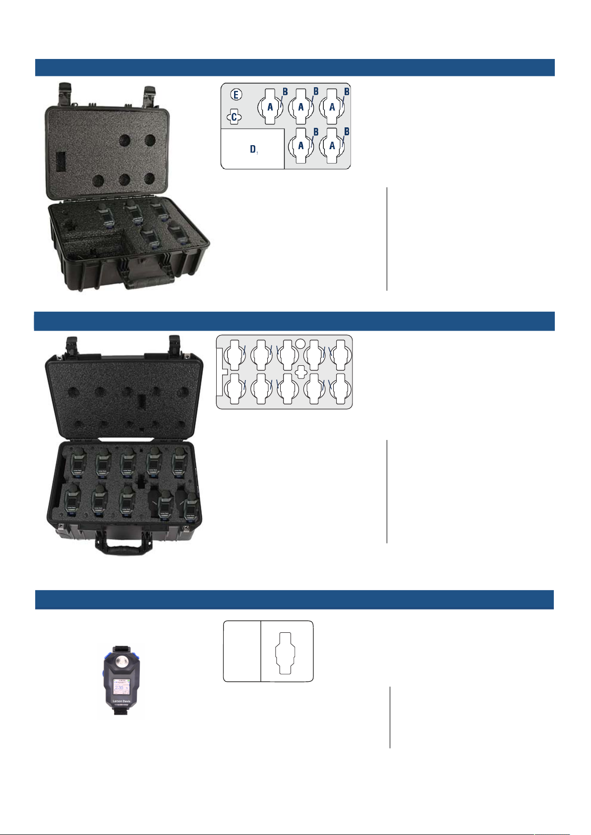
3-Pack With Charging Case
• Spartan 730 Quick Start Guide
• LD Bluetooth dongle (DVX016)
• Electrical outlet adapter
• USB to micro-B cable (CBL218)
• 1 set of 2” safety pins
• Spartan 730 Quick Start Guide
• LD Bluetooth dongle (DVX016)
• Electrical outlet adapter
• USB to micro-B cable (CBL218)
• 5- port USB charger
• Spare 1/4” calibrator adapter
• 3 sets of 2” safety pins
• LD USB drive contains:
G4 LD Utility Software
Copy of Calibration Certificate
Spartan 730 Reference Manual
A. Three (3) Model 730 Dosimeters (730) with
windscreens and clothing clips
B. Three (3) Qi® wireless charging pads (PSA042)
C. Calibrator (CAL150) with 1/4” adapter
D. LD USB drive:
E. Cables & Accessories include:
• LD USB drive contains:
G4 LD Utility Software
Copy of Calibration Certificate
Spartan 730 Reference Manual
730 Dosimeter Reference Manual Rev B 3
Page 7
5-Pack With Charging Case
C
AA
D
E
A
AAA A
AAA
AA
B
B
B
B
B
B
E
D
E
A
A. Five (5) Model 730 Dosimeters (730) with
windscreens and clothing clips
B. Five (5) Qi® Wireless Charging Pads (PSA042)
C. Calibrator (CAL150) with 1/4” adapter
D. LD USB drive
E. Cables & Accessories include:
10-Pack With Charging Case
• Spartan 730 Quick Start Guide
• LD Bluetooth dongle (DVX016)
• Electrical outlet adapter
• 2 USB to micro-B cables (CBL218)
• 5-port USB charger
• Spare 1/4” calibrator adapter
• 5 sets of 2” safety pins
• Spartan 730 Quick Start Guide
• LD Bluetooth dongle (DVX016)
• Electrical outlet adapter
• 2 USB to micro-B cables (CBL218)
• 10-port USB charger
• Spare 1/4” calibrator adapter
• 10 sets of 2” safety pins
• LD USB drive contains:
G4 LD Utility Software
Copy of Calibration Certificate
Spartan 730 Reference Manual
A. Ten (10) Model 730 Dosimeters with
windscreens and clothing clips (730)
B. Ten (10) Qi® wireless charging pads (PSA042)
C. Calibrator (CAL150) with 1/4” adapter
D. LD USB drive
E. Cables & Accessories include:
• LD USB drive contains:
G4 LD Utility Software
Copy of Calibration Certificate
Spartan 730 Reference Manual
730 Dosimeter
730 Dosimeter Reference Manual Rev B 4
• Spartan 730 Quick Start Guide
• USB to micro-B cable (CBL218)
• 2” safety pins (for heavy clothing)
A. Model 730 Dosimeter (730) with windscreen
and clothing clips
D. LD USB drive
E. Cables & Accessories include:
LD USB drive includes:
Microphone Certification
G4 LD Utility Software for PC
Spartan 730 Reference Manual
Page 8

1.0.2 Serial Numbers
TRY THIS We recommend that you
record the purchase date, model,
and serial numbers for your
instrument.
1.0.3 Basic Operations
The Spartan 730 dosimeter’s model and serial number is printed on the
label on the back of the meter. The microphone serial number is
engraved on the outside of the microphone.
The Spartan 730 performs the following operations:
TRY THIS Press and hold the Select
button to explore the menu.
• Measures sound exposure using: stop, pause, and resume
measurement.
• Displays sound measurement data on a full-color LCD screen. You
can also view the same data in the G4 LD Utility for PC, and in
the LD Atlas app for mobile devices.
• Allows you to view live data while a measurement is in process.
• Logs simultaneously to time, statistical measurement, and event
histories.
• Allows you to enter speech-to-text, or text note markers to mark
portions of the measured sound history.
• Automatically backs up data to prevent data loss on power failure.
• Auto-calibrates when a precision acoustic calibrator is attached,
and stores calibration history.
• Includes time stamps for L
max
, L
min
, L
peak-(max)
single event
metrics.
• Syncs the device clock with your PC or mobile device.
• Capable of measuring sound exposure according to 4 different
dosimeter configurations at one time, when you enable
additional virtual dosimeters.
1.0.4 Applications
1.0.5 Hardware Features
• Records sound events in 16-bit WAV format by using event
detectors.
The Spartan 730 personal noise dosimeter is ideal for the following
applications:
• Measuring factory, airport, and mine noise
• Measuring construction noise
• Developing engineering noise controls
• Determining occupational safety compliance
• Collecting data for legal proceedings
The Spartan 730 includes the following hardware features:
• 8 GB internal, non-volatile flash memory
• 176 x 176 color LCD very high contrast display with front light
730 Dosimeter Reference Manual Rev B 5
Page 9

1.0.6 Performance Features
• Durable, sealed plastic case
• Rechargeable lithium-Ion battery with over 40 hrs. run time
• Bluetooth LE (low energy) wireless personal area network
connection to your PC or mobile device
• USB 2.0 high-speed micro-B peripheral connector for remote
control and data download to a PC.
For more information on these features, refer to A.2 Spartan Model 730
Instrument Specifications.
• Multi-color LEDs on front indicate exceeded Action and Limit
Levels
• Daily Timer (up to 3 periods/day)and Timed Stop Timer
• Lockable user interface to protect measurement data
• Noise detection/microphone accuracy. For details, see A.2
Spartan Model 730 Instrument Specifications.
• RMS Detectors: Slow, Fast & Impulse
• RMS Frequency Weighting: A, C & Z
1.0.7 Available Options
1.0.8 Accessories
• Peak Frequency Weighting: A, C & Z
• Multiple language support: English, Spanish, French, Italian,
German, and Portuguese
The following optional firmware is available for the Spartan 730
dosimeter:
• “Setting Event Sound Recording Options” (730-ESR)
• “Using the Octave Band Analysis Feature” (730-OB1)
The following items are available separately from Larson Davis:
• Additional Qi® wireless charging pads
• Additional 1/4-inch calibrator adapters (ADP109)
• Additional USB to micro-B cable (CBL218)
• Additional power supply cable with accessory plug ends (PSA029)
• Additional 1-inch Windscreens (WS012)
730 Dosimeter Reference Manual Rev B 6
Page 10
1.1 Dosimeter Overview
This section describes the hardware and device components of the
Spartan 730 Noise dosimeter. For more information, see “ Spartan
Model 730 Instrument Specifications” on page A-1.
FIGURE
730 Dosimeter Instrument Overview (front)
Select Button
Power Button
Color Display
Charger & Alarm
Status LEDs
Durable, removable Clothing
Clips
Microphone &
Preamplifier
Up Button
Down Button
Bluetooth®
Connectivity
Battery with Qi®
Wireless Charging
Durable, removable
Microphone Windscreen
Windscreen (WS012)
Wind blowing across the microphone generates pressure fluctuations
on the microphone diaphragm. This can contribute to an inaccurate
measurement. To achieve the best result, we recommended using the
WS012 windscreen provided with this model. The Larson Davis WS012
windscreen is a 1” diameter cone made of open cell foam, which
contributes to the most accurate measurement.
1.1.1 Buttons
LEARN MOREYou can also begin a
measurement from the LD Atlas
app or G4
information, see the
TM
LD Utility. For more
Spartan
TM
Noise Dosimeter Quick Start
Guide.
730 Dosimeter Reference Manual Rev B Dosimeter Overview 7
The Spartan Model 730 dosimeter has 4 buttons to power, navigate
displays, access or exit menus, and to start or stop a measurement.
They include power, select, up, and down, as shown in the figure
above.
Page 11
Using the Buttons to Start/Stop a Measurement
Step 1. Power on the dosimeter.
Step 2. Press and hold select to enter the Menu.
Step 3. Highlight, then select Run . The measurement begins.
To stop the measurement, highlight, then select stop .
1.1.2 Navigating On the LCD Color Display
The Spartan 730 has a full color, back lit LCD. When you power the
dosimeter on, you’re prompted to press select to open the Menu,
or press up or down button to dismiss the tip. For more
information about accessing and using the menu to access the
dosimeter settings, see the section Section 6 Dosimeter Settings
Reference.
Within the main display, there are 8 screens. Press select to
navigate to the right. Quick press power to navigate to the left.
Within each screen, press the down button to view additional
pages on that screen. Click on the screens in the table below to learn
more about the contents of each.
LEARN MORE
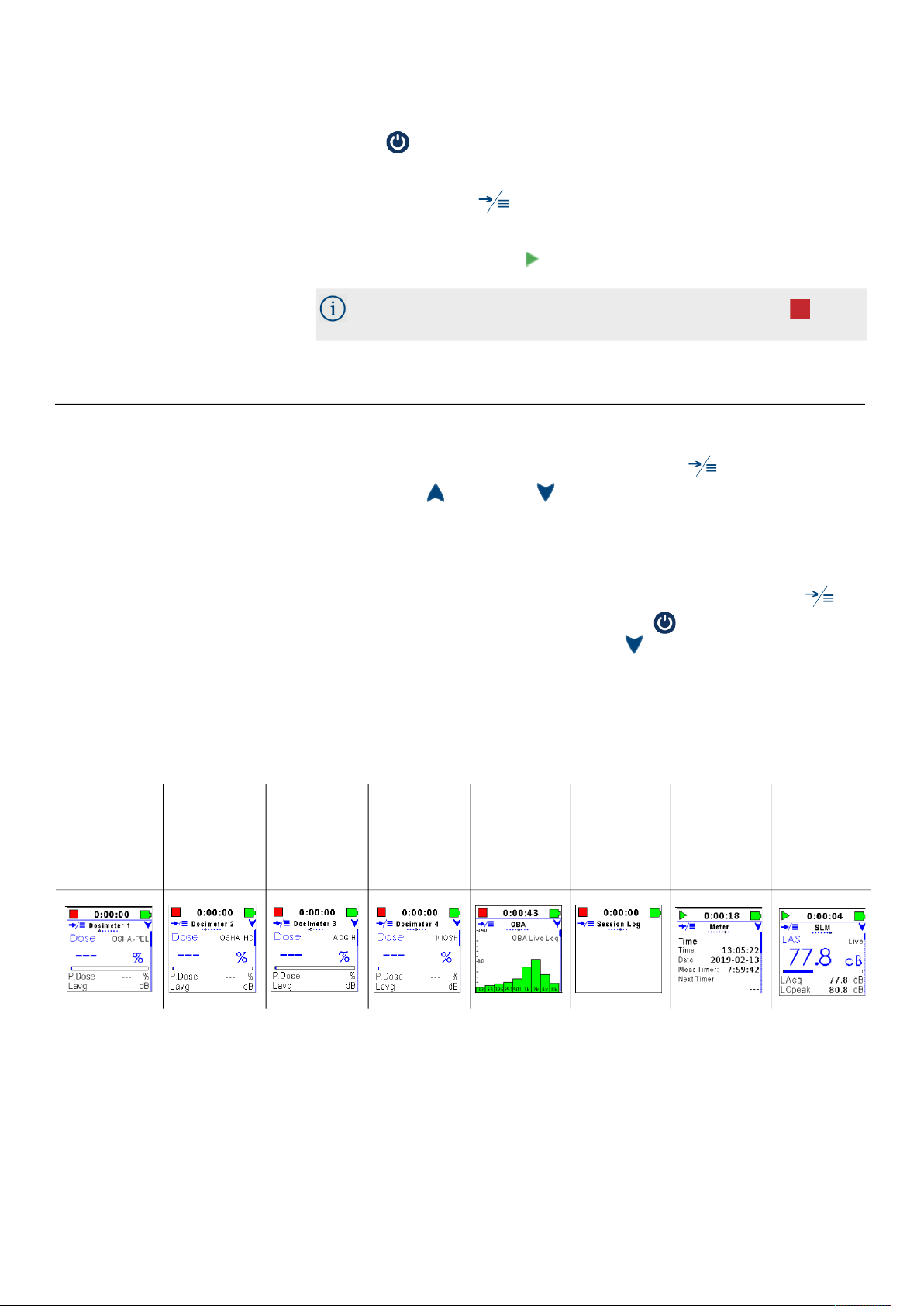
Table 1.1 Screens On the Spartan 730 Dosimeter
Dosimeter
1–4 Screen
Detail
Dosimeter
1–4 Screen
Detail
Dosimeter
1–4 Screen
Detail
Dosimeter
1–4 Screen
Detail
The first 4 screens show Dosimeter 1 and virtual dosimeters (2, 3, 4).
Selecting a configuration for Dosimeters 2, 3, and 4 allows you to view
the current measurement data in those metrics in addition to the
Dosimeter 1 metrics. For more information about measurement
configurations, see 3.2 Setting a Measurement Configuration On the
Dosimeter.
OBA
Screen
Detail
Session
Log
Screen
Detail
Meter
Screen
Detail
SLM
Screen
Detail
730 Dosimeter Reference Manual Rev B Dosimeter Overview 8
Page 12
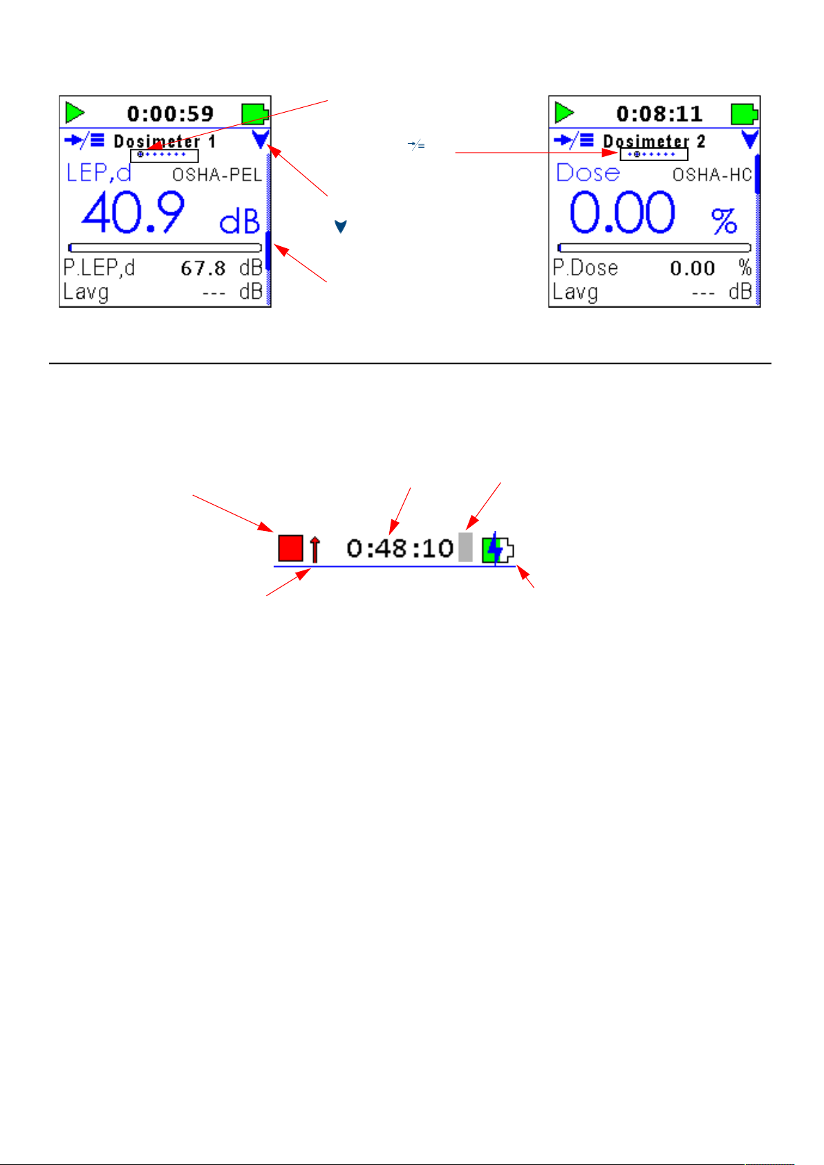
FIGURE Screen and Page Indicators
1.1.3 Status Bar
The screen indicator
shows the current
position is Screen 1.
Press
select to
advance to Screen 2.
The Down icon indicates
you can press the
button to view
additional pages on this
screen. The scroll bar
shows your page
position.
down
The Status Bar displays the following information, if and when each
indication applies.
FIGURE
Status Bar Detail
Overload indicator
Run time of current
measurement
Battery Indicator
The green fill of the battery icon indicates the state of the battery
charge by volume. The blue bolt symbol appears over the battery icon
if the battery is currently charging, as shown in 1.1
When the battery is fully charged, the green level on the indicator
completely fills the battery shape, and the blue charge bolt no longer
appears.
Bluetooth connectedRun Status
Battery and Charge
indicator
Additionally, when your Spartan 730 is connected to a power source,
the green LED front light indicates the meter is charging.
External Power Indicator
For more information about connecting to an external power source,
see section 2.3 Charging the Spartan 730.
Overload Indicator
The Spartan 730 overload indicator, as shown in 1.1, lets you know
when the dosimeter’s calibrated input range has been exceeded. For
730 Dosimeter Reference Manual Rev B Dosimeter Overview 9
Page 13
more information, see section 3.2.1 Larson Davis Calibrator &
Accessories.
Run Status
The status of the meter is indicated by the Run Status icon, as shown in
1.1. The Run Status includes the following states: run, stop, and pause.
Data Labels
The labels for sound metrics on the Spartan dosimeter are designated
by international standards. For many displayed values, the frequency
and time weighting are indicated in the name of the metric.
For example, L
is the A-weighted sound pressure level measured
AS
using the Slow detector. Sound pressure level is often referred to as
SPL. For definitions and details on the sound metrics available on this
dosimeter, see Glossary of Terms on page B-16.
1.1.4 Screen Details On the Spartan 730 Dosimeter
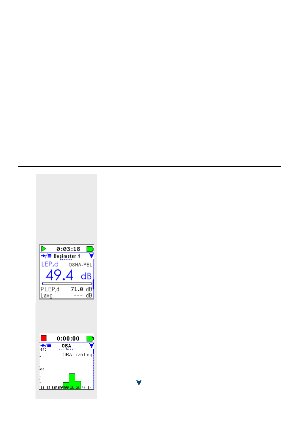
Dosimeter 1–4 Screen Detail
The Spartan 730 dosimeter configuration settings are displayed on the
first 4 screens of the LCD. The LCD displays the current measurement
data in terms of your chosen configuration for Dosimeter 1.
Additionally, when you select a configuration for the virtual dosimeters
Dosimeter 2, 3, and 4, you can view the current data in terms of other
configurations or standards.
• Dosimeter screens 1-4, when enabled, show your chosen noise
exposure metrics for the following standards:
• OSHA-PEL
• OSHA-HC
• ACGIH
• NIOSH
• ISO
• Custom
Click here to return to Table 1.1 Screens On the Spartan 730 Dosimeter.
OBA Screen Detail
The OBA screen shows a bar chart of live data, which contains the most
commonly used octave frequencies.
For detailed information about OBA, see A.5 Model 730 Optional OBA
Software Specifications.
Press down to view additional pages.
730 Dosimeter Reference Manual Rev B Dosimeter Overview 10
Page 14
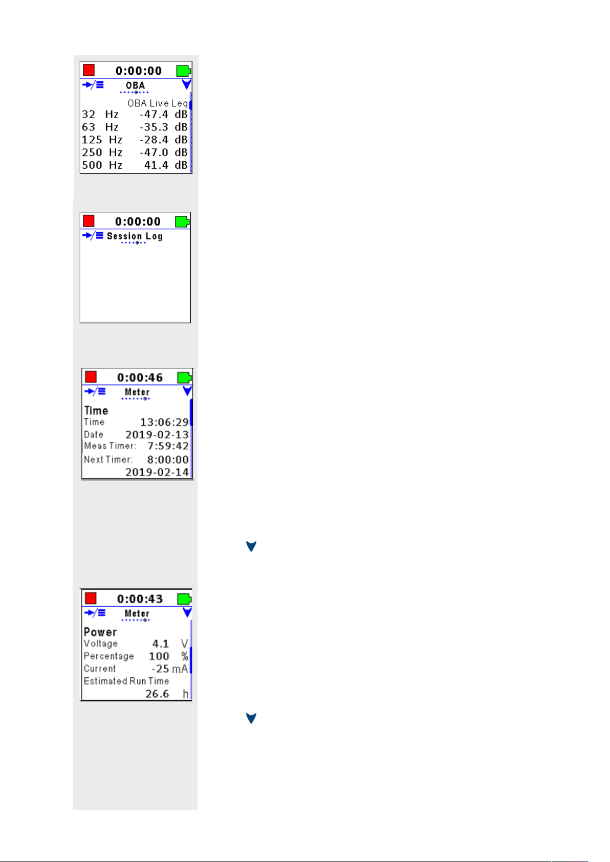
Subsequent pages show OBA data in table format.
The OBA Screen and associated features display when you purchase
and install option 730-OB1.
Click here to return to Table 1.1 Screens On the Spartan 730 Dosimeter.
Session Log Screen Detail
The Session Log screen shows a record of actions performed on the
meter during the current measurement.
• Session Log information is also available in the LD Atlas app and
in G4.
Click here to return to Table 1.1 Screens On the Spartan 730 Dosimeter.
Meter Screen Detail
The Meter screen displays the following information on 3 pages:
Meter–Time Page 1
• Time, which displays the current date and time of day
• Measurement Timer, which displays the time remaining before a
scheduled stop when using a Timed Stop or Daily Timer.
• Next Timer, which displays the date and time the next timer run
or stop will occur when using the Daily Timer.
Press to view additional pages on the Meter Screen.
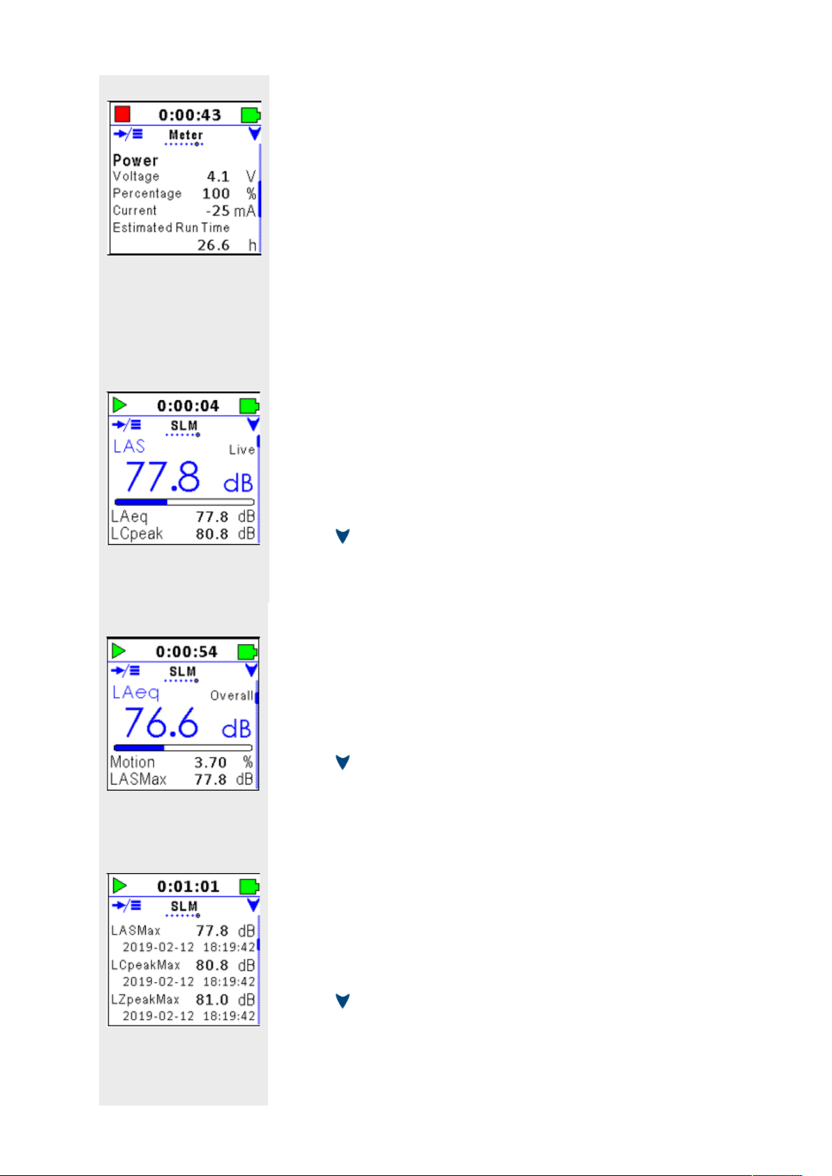
Meter–Power Page 2
• Power, which displays the battery voltage
• Battery life remaining, expressed as a percentage
• Current flowing into (+) or out of (–) the battery in mA.
• Estimated Run Time, which displays the amount of time the
dosimeter can measure noise on the current battery power.
Press to view additional pages on the Meter Screen.
730 Dosimeter Reference Manual Rev B Dosimeter Overview 11
Page 15
Meter–Other Page 3
• Free Memory, which displays the memory currently available for
data storage
• Total Memory, available for storage
• the current internal device Temperature
Click here to return to Table 1.1 Screens On the Spartan 730 Dosimeter.
SLM Screen Detail
The SLM screen displays the following sound level meter metrics on 10
pages.
SLM–Live, Page 1
• Displays the following metrics with frequency A, C, or Z and time
weighting S, F, I, or Peak subscripts.
• Live Sound Pressure level (L
• 1 second equivalent Level (L
• 1 second peak level (L
AS
)
)
Aeq
)
Cpeak
Press to view additional pages on the SLM Screen.
SLM–Overall, Page 2
• Displays the following metrics with frequency A, C, or Z and time
weighting S, F, I, or Peak subscripts. Overall Equivalent Level
(L
)
Aeq
• Overall Motion percentage
• Overall Maximum Level (L
ASMax
)
Press to view additional pages on the SLM Screen.
SLM–Maximums, Page 3
• Displays the single event maximum levels with the time of
occurrence
• Overall Maximum Level and Time
• Overall C peak Level and Time
• Overall Z peak Level and Time
Press to view additional pages on the SLM Screen.
730 Dosimeter Reference Manual Rev B Dosimeter Overview 12
Page 16
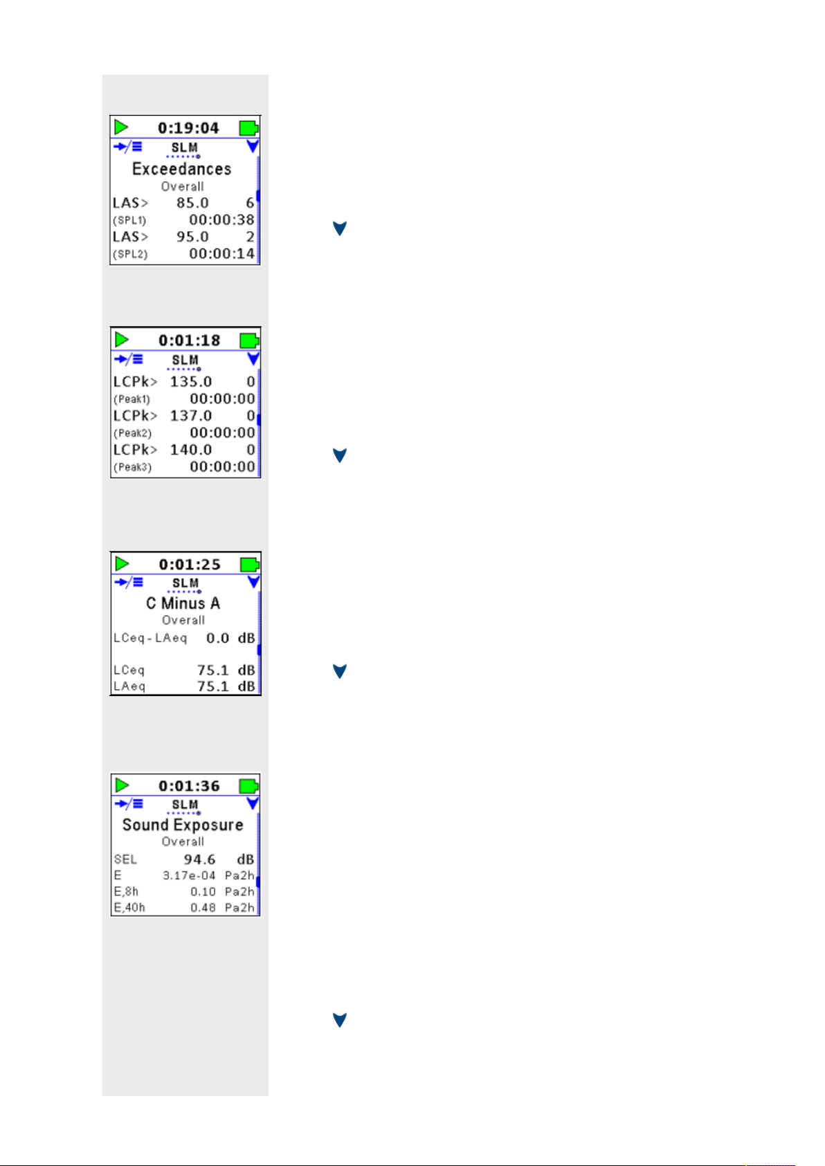
SLM–SPL Exceedances, Page 4
• Displays the SPL Exceedance trigger-level settings
• The number of trigger occurrences
• The duration over the trigger level for 2 SPL trigger levels
Press to view additional pages on the SLM Screen.
SLM–Peak Exceedances, Page 5
• Displays three Peak Exceedance trigger-level settings
• The number of Peak occurrences
• The duration over the trigger level for each trigger level
Press to view additional pages on the SLM Screen.
SLM–C Minus A Overall, Page 6
• Use this data to determine the low frequency content of the sound
measured.
• (Shown here: LCeq – LAeq)
Press to view additional pages on the SLM Screen.
SLM–Sound Exposure, Page 7
• Displays the Sound Exposure metric in dB and in Pascal-squared
hours
• SEL
• E
• E,8h
• E,40h
LEARN MOREFor more information about the Sound Exposure metric, view the
definition in
“Glossary of Terms” on page B-16.
Press to view additional pages on the SLM Screen.
730 Dosimeter Reference Manual Rev B Dosimeter Overview 13
Page 17

SLM–Sound Exposure, Page 8
LEARN MOREFor more information about the Sound Exposure metric, view the
definition in
“Glossary of Terms” on page B-16.
• Displays the Sound Exposure metric in dB and in Pascal-squared
seconds
• SEL
• E
• E,8h
• E,40h
Press to view additional pages on the SLM Screen.
SLM–Any-Level 1-second, Page 9
• Displays sound exposure levels for A, C, and Z frequency
weightings
• Slow (S), Fast (F), Impulse (I), linear time (Leq), and peak time
weightings (LPk) for the previous 1 second.
1.1.5 Battery
Press to view additional pages on the SLM Screen.
SLM–Any-Level Overall, Page 10
• Displays sound exposure levels for A, C, and Z frequency
weightings
• Slow (Smx), Fast (Fmx), Impulse (Imx), linear time (Leq), and peak
time weightings (LPk) for the overall measurement.
Click here to return to Table 1.1 Screens On the Spartan 730 Dosimeter.
When fully charged and under normal use with basic features enabled,
the included battery powers the dosimeter for 40–50 hours of run time.
When fully discharged, the included battery can recharge in under 3
hours.
The Spartan dosimeter has the following power indicators:
• (visual indicator) Battery indicator on the LCD Display (See 1.1.3
Status Bar)
• (visual indicator) Battery indicator in G4
• (visual indicator) Battery Indicator in LD Atlas app
• (percent charge) Meter Screen Detail
730 Dosimeter Reference Manual Rev B Dosimeter Overview 14
Page 18

• (hours) Estimated Run Time on the Meter Screen
1.1.6 Charger and Alarm Status LEDs
When connected to an external power source, the green LED is active.
When enabled, the LED alarm lights on the Spartan 730 provide
exposure feedback to the wearer based on the Source metric, and the
Action and Limit levels you set. The lights display a range of yellow
(action) to red (limit) .
1.1.7 Care and Cleaning
The Spartan 730 contains a durable, sealed plastic case. When needed,
remove the microphone windscreen and wipe the dosimeter with a
damp cloth.
If needed, Larson Davis offers replacements for the microphone
windscreen, clothing clips, cables, power supply, and wireless charger
on the Spartan 730 Dosimeter Support page at www.LarsonDavis.com.
Recommended Next Step: Section 2 Getting Started
730 Dosimeter Reference Manual Rev B Dosimeter Overview 15
Page 19

Section 2 Getting Started
2.1 Installing G4 ................................................................................................. 16
2.1.1 Installing G4 from the Web ....................................................................................16
2.1.2 Installing G4 from the LD USB Drive ...................................................................... 17
2.2 Installing LD Atlas App for Mobile Devices ................................................. 17
2.3 Charging the Spartan 730 ........................................................................... 17
2.3.1 Wireless Charging .................................................................................................. 17
2.3.2 Charging by Using a USB Cable ............................................................................. 19
2.4 Connecting to Your Dosimeter .................................................................... 19
2.4.1 Spartan Dosimeter to PC via BT ............................................................................ 19
2.4.2 Spartan Dosimeter to PC via USB ......................................................................... 20
2.4.3 Spartan Dosimeter to Mobile Device via BT .........................................................21
2.5 Calibrating Your Spartan Dosimeter .......................................................... 22
2.5.1 Calibration Overview ............................................................................................. 23
2.5.2 Larson Davis Calibrator & Accessories .................................................................. 24
2.6 Installing the Dosimeter On the Wearer ..................................................... 26
2.1 Installing G4
G4 LD Utility (G4) software enhances the features, flexibility, and
ease-of-use of Larson Davis instruments. Use it to set up, calibrate,
and remotely operate the Spartan dosimeter. Additionally, you can
use G4 to download, chart, and analyze measurement data files, print
and share a custom report, and export data to third-party software for
post-processing and analysis.
2.1.1 Installing G4 from the Web
This process also works well if you want to update a currently installed
version of G4.
Step 1. In your browser, navigate to www.LarsonDavis.com >> Support >>
Dosimeters.
Step 2. On the Dosimeters Support page, select the Spartan 730.
Step 3. On the Spartan Model 730 Support page, click on the G4 LD Utility link.
Step 4. On the G4 LD Utility Software Support page, click the link for the full
installer. The file downloads to your PC in ZIP format.
730 Dosimeter Reference Manual Installing G4 16
Page 20

Step 5. When the download is complete, extract and install the upgrade. G4
creates a shortcut icon on th Desktop and a PCB Piezotronics folder
in your Start Menu.
2.1.2 Installing G4 from the LD USB Drive
Step 1. Insert the included Larson Davis USB drive into a USB port in your PC.
Step 2. Launch the Windows Explorer, and open the USB Drive (Removable
Disk).
Step 3. Open the G4 LD Utility Software folder, and double-click LDSetup.exe.
This installs the G4 software, creates a PCB Piezotronics folder in your
Start Menu, and creates a shortcut to G4 on your Desktop.
Step 4. Double-click the G4 shortcut icon on your Desktop.
2.2 Installing LD Atlas App for Mobile Devices
The app is available for Android from the Google Play
Store®
With an established Bluetooth connection, you can use the
LD Atlas app to set up, calibrate, and remotely operate the
SoundAdvisor; remotely monitor a measurement in progress,
download and chart the resulting data, and print and share a custom
report.
To install the app: open the app store on your mobile device, search for
“LD Atlas,” and follow the prompts.
2.3 Charging the Spartan 730
TAKE NOTE The time to charge the
battery is about 3 hours.
You can charge the Spartan 730 by using a wireless charging pad, or the
included USB to Micro-B cable (CBL218).
In this section:
2.3.1 Wireless Charging
•
• 2.3.2 Charging by Using a USB Cable
1
, or for iOS from the Apple App Store®.2
2.3.1 Wireless Charging
The Spartan 730 is built with a convenient wireless charging capability.
Charge the meter using any of the following wireless methods.
1. Android is a trademark of Google LLC.
2. Apple and iPhone are trademarks of Apple Inc., registered in the U.S. and
other countries.
730 Dosimeter Reference Manual Rev B Installing LD Atlas App for Mobile Devices 17
Page 21

Using the Charging Case for Wireless Charging
Step 1. Set the dosimeter in the Amazing
Charging Case assembly with Qi®
wireless charging pad in the protective
foam liner, and plug the case power
cord into a wall socket.
Step 2. When connected to an external power
source, the green LED on the front of
the dosimeter is active.
Step 3. Press and hold power on the
dosimeter to power the meter on. To
power off, press and hold power for 3
seconds.
Using a Qi® Wireless Charging Pad
Step 1. Plug the Qi® Wireless charging pad
into a wall outlet, and set the
dosimeter on the charging pad.
Step 2. When connected to an external
power source, the green LED on
the front of the dosimeter is
active.
Step 3. Press and hold power on the
dosimeter to power the meter on.
To power off, press and hold
power for 3 seconds.
730 Dosimeter Reference Manual Rev B Charging the Spartan 730 18
Page 22

2.3.2 Charging by Using a USB Cable
Dosimeter to PC via USB
Step 1. Using the included USB to micro-
B cable (CBL218), plug the microB end of the cable into the
dosimeter’s USB port.
Step 2. Plug the USB end into an open
USB port on your PC. The meter
begins charging. When
connected to an external power
source, the green LED on the
front of the dosimeter is active.
Step 3. Press and hold power on the
dosimeter to power the meter
on. To power off, press and hold
power for 3 seconds.
Dosimeter to Electrical Outlet via USB and Power Adapter
Step 1. Using the included USB to micro-B cable (CBL218), plug the micro-B end
of the cable into the dosimeter’s USB port.
Step 2. Plug the USB end into the included power adapter (PSA029).
Step 3. Attach the included electrical outlet plug that matches your electrical
outlet, then plug the power adapter into an electrical outlet. The meter
begins charging. When connected to an external power source, the
green LED on the front of the dosimeter is active.
2.4 Connecting to Your Dosimeter
In this section:
2.4.1 Spartan Dosimeter to PC via BT
•
• 2.4.2 Spartan Dosimeter to PC via USB
• 2.4.3 Spartan Dosimeter to Mobile Device via BT
2.4.1 Spartan Dosimeter to PC via BT
Before you begin:
• Install the G4 LD Utility. For help doing this, see 2.1 Installing G4.
• Charge your dosimeter and power it on. For more information, see
2.3 Charging the Spartan 730.
730 Dosimeter Reference Manual Rev B Connecting to Your Dosimeter 19
Page 23

TAKE NOTE Because the Spartan
730 uses a Bluetooth® Low Energy
(BLE) connection, there is no need to
pair.
Step 1. Enable BT for your PC.
Step 2. To launch G4, click the shortcut icon on your Desktop.
Step 3. In G4, click on your connected Spartan dosimeter in the Meters panel.
A Bluetooth (BT) connection is established when the BT feature is
enabled and the dosimeter is near your PC with no obstructions.
Win 7 Users: Insert the included LD Bluetooth Dongle (DVX016) into an
available USB slot.
Win 10 users: For more information about enabling Windows BT, click the
Start Menu and search for Bluetooth.
This opens a new Meter tab on the right.
Your Spartan dosimeter’s name is “730” plus the serial number.
Ex: 730 100
Connected meters
display with a blue
dosimeter icon.
LEARN MORE For information about changing the name of your dosimeter,
see section 6.5.1 Naming the Dosimeter.
For more
information about
these icons, see 5.6
Meters Panel
Overview.
Step 4. To view the dosimeter’s LCD display in G4, click Live View.
Recommended Next Step:
2.5 Calibrating Your Spartan Dosimeter
2.4.2 Spartan Dosimeter to PC via USB
Connect the dosimeter to your PC using the included USB to micro-B
cable (CBL218) as described in this section. For more information on
working with G4 LD Utility, refer to the G4 LD Utility Software Manual.
Step 1. Connect the 730 Dosimeter to PC with the provided USB to micro-B
cable. (CBL218).
Step 2. To launch G4, click the shortcut icon on your Desktop.
730 Dosimeter Reference Manual Rev B Connecting to Your Dosimeter 20
Page 24

Step 3. Locate and click on your connected Spartan dosimeter in the Meters
panel. This opens a new Meter tab on the right.
Your Spartan dosimeter’s name is “730” plus the serial number.
Ex: 730 100
Connected meters
display with a blue
dosimeter icon.
LEARN MORE For information about changing the name of your dosimeter,
see section 6.5.1 Naming the Dosimeter.
For more
information about
these icons, see 5.6
Meters Panel
Overview.
Step 4. To view the dosimeter’s LCD display in G4, click Live View.
Recommended Next Step:
2.5 Calibrating Your Spartan Dosimeter
2.4.3 Spartan Dosimeter to Mobile Device via BT
Before you begin:
• Download the LD Atlas app. For help with this, see 2.2 Installing LD
Atlas App for Mobile Devices.
• Charge your dosimeter and power it on. For more information, see
2.3 Charging the Spartan 730.
Connect to the 730 Dosimeter using your mobile device’s Bluetooth
radio. Because the Spartan 730 uses a Bluetooth® Low Energy (BLE)
connection, there is no need to pair.
On your mobile device, enable the Bluetooth feature.
Step 1. Tap to open the LD Atlas app.
Step 2. Tap on the name of your connected dosimeter in the Meters panel. This
opens the Meters screen.
730 Dosimeter Reference Manual Rev B Connecting to Your Dosimeter 21
Page 25

Your Spartan dosimeter’s name is “730” plus the serial number.
Ex: 730 100
Connected meters
display with a blue
dosimeter icon.
LEARN MORE For information about changing the name of your dosimeter,
see section 6.5.1 Naming the Dosimeter.
For more
information about
these icons, see 5.6
Meters Panel
Overview.
Step 3. To view the dosimeter’s LCD display in the app, tap the Live View icon.
Recommended Next Steps:
2.5 Calibrating Your Spartan Dosimeter
2.5 Calibrating Your Spartan Dosimeter
LEARN MORE Refer to the
calibrator’s operating instruction for
more information.
Step 1. Press and hold power on the dosimeter.
Step 2. Remove the windscreen by pressing down and turning counter-
Your Spartan 730 dosimeter begins auto-calibrating when attached to a
CAL150 or CAL200 calibrator.
Before you begin:
• If you want to track the meter’s calibration history (recommended),
connect your dosimeter to the G4 LD Utility software via a Bluetooth
or USB connection.
• If needed, stop the measurement in progress.
clockwise. .
Step 3. Insert the microphone into the opening on the bottom of the calibrator.
The adapter (ADP109) is required for a proper fit.
730 Dosimeter Reference Manual Rev B Calibrating Your Spartan Dosimeter 22
Page 26

Step 4. Press power on the side of the calibrator. The dosimeter detects the
calibrator’s tone and begins calibrating. For best results, don’t move the
dosimeter during calibration.
Step 5. When Accept Cal? appears on your LCD display, press select
to accept.
To reject the calibration, press down , remove the
calibrator, and repeat from step 3.
Step 6. Replace the windscreen on the microphone.
LEARN MORE For more information
on this topic, see"Microphone
Guidelines" on B-27.
2.5.1 Calibration Overview
LEARN MORE See"Calibration
Check" on B-17 in the Appendix B-
Glossary.
Recommended Next Step:
2.6 Installing the Dosimeter On the Wearer
Calibrating your Spartan 730 helps you determine the true sensitivity of
your dosimeter–including all effects from the microphone,
preamplifier, and dosimeter. It also establishes a numeric relationship
between the sound pressure level at the diaphragm of the microphone
and the voltage of the meter. Once this relationship is established, the
meter accurately displays the sound pressure level.
The Spartan 730 is equipped with an auto-calibration feature to
simplify this process. As shown in section 2.5 Calibrating Your Spartan
Dosimeter, when the calibration levels are measured, the 730
dosimeter displays the resulting levels and gives you the opportunity to
accept the calibration, or to reject and begin the process again.
FIGURE: Accepting Calibration Details
LCeq is the dB level measured with the
calibrator tone applied.
Delta is the difference between that
measured level and the calibrator’s
output level.
730 Dosimeter Reference Manual Rev B Calibrating Your Spartan Dosimeter 23
Page 27

Overload Condition
During calibration, your meter determines the overload level (dB Peak)
for A, C and Z frequency weightings.
Simply stated, the overload level is the sound pressure level in dB that
would overload the instrument. This can occur when a signal from the
preamplifier exceeds the calibrated input range of the dosimeter.
When this condition exists, the Spartan 730 displays an Overload
indicator on the LCD display, in the LD Atlas app, and in the G4 LD
Utility.
FIGURE: Spartan 730 Overload Indicator in the LCD Display
Overload indicator
Calibration Stability
The Spartan 730 maintains a stable value of sensitivity over long
periods of time. As part of the meter’s auto-calibration, the result is
documented as the Calibration History.
TAKE NOTE Your copy of the
calibration certificate is on the
included Larson Davis USB drive.
After the auto-calibration, the dosimeter makes an automatic
comparison of the meter’s current sensitivity value and the value from
the previous calibration. If the difference is greater than 3 dB, the meter
displays a Large Change Notification as shown below.
FIGURE: Spartan Dosimeter Large Change Notification
This screen notifies you that the dosimeter’s current
sensitivity is different from the previously measured
sensitivity.
Changes like this may indicate that it’s time for your
dosimeter to be serviced.
We recommend that you maintain your dosimeter’s calibration history.
Significant changes in sensitivity, or a pattern of small but regular
sensitivity changes, indicate that your dosimeter should be serviced.
Your dosimeter has been calibrated and certified to exact
specifications. We recommend that you re-certify the calibration
annually. We can also schedule the recertification service based on
your requirements.
To contact Larson Davis, see Contact Larson Davis.
2.5.2 Larson Davis Calibrator & Accessories
The Spartan 730 dosimeter accommodates the following calibrators
with a 1/4-inch adapter (ADP109).
730 Dosimeter Reference Manual Rev B Calibrating Your Spartan Dosimeter 24
Page 28

TRY THIS Press the power button on
the side of the calibrator to activate
it. It automatically powers off after 1
minute.
• Larson Davis Model CAL150 or CAL200: 94/114 dB @ 1 kHz
1/4-inch adapter
(ADP109)
About the Adapter (ADP109)
The CAL150 and CAL200 calibrators require a
1/4-inch adapter (ADP109). If your dosimeter
package included a calibrator, the 1/4-inch
adapter was attached. If needed, additional
adapters are available from Larson Davis
Technical Support.
To install the adapter, firmly insert the narrow
edge into the slot on the bottom of the
calibrator. The adapter’s part number should
be visible around the circumference.
About Post-Calibration Data
We recommend that you post-calibrate directly after the measurement
and prior to downloading the data files. This creates a postmeasurement entry in the Calibration History.
After you post-calibrate, connect to G4. When downloading data files,
your Spartan dosimeter appends the most recent post-calibration
values to each file as it downloads.
If you post-calibrate after the data files download, connect your
dosimeter once again to G4 or the Atlas app. Both utilities will attempt
to add post-calibration values to a data file when you open it.
If you format and restore to factory defaults, all calibration history is
deleted except for the single, most recent post-calibration values. This
entry becomes the initial entry of a new Calibration History record.
730 Dosimeter Reference Manual Rev B Calibrating Your Spartan Dosimeter 25
Page 29

2.6 Installing the Dosimeter On the Wearer
LEARN MOREFor more information
about gathering the most accurate
noise measurement, see 4.2 Best
Practices for Measuring Noise
Exposure.
Clip the dosimeter to clothing on the worker’s shoulder, with the
microphone nearest to the ear. It may be effective to consider the
worker’s position in relation to the loudest sounds in the environment,
and to secure the dosimeter on the shoulder most exposed to the noise
source.
Recommended Next Step:
3.2 Setting a Measurement Configuration On the Dosimeter
730 Dosimeter Reference Manual Rev B Installing the Dosimeter On the Wearer 26
Page 30

Section 3 Setting a Measurement Configuration
T
he Spartan 730 dosimeter calculates the current noise exposure
according to your chosen configuration for Dosimeter 1. You can also
enable up to 3 additional virtual dosimeter configurations (Dosimeter
2, 3, and 4).
The dosimeter displays preset configurations based on international
noise exposure standards. Use these presets as listed, customize one
or more options of a preset, or create a custom configuration. The
following presets are available:
• OSHA-HC
• OSHA-PEL
• NIOSH
• ACGIH
• ISO 9612
• Custom
3.1 Setting a Measurement Configuration On the Dosimeter ......................... 27
3.2 Setting a Custom Configuration .................................................................29
3.3 Saving a Configuration to the Dosimeter in G4 .......................................... 30
3.4 Saving a Configuration Setup File in G4 ..................................................... 30
3.5 Importing a Configuration Setup File to a Dosimeter ............................... 31
3.6 Default Dosimeter Settings ......................................................................... 32
3.1 Setting a Measurement Configuration On the Dosimeter
In this section, select a configuration for Dosimeter 1 using the
Spartan 730 buttons and LCD.
Before you begin:
• Power on your dosimeter.
• If applicable, stop the measurement in progress.
730 Dosimeter Reference Manual Setting a Measurement Configuration On the Dosimeter 27
Page 31

TAKE NOTE You can also set up
measurement configurations for
virtual dosimeters from the LD Atlas
app and from the G4 LD Utility. For
details, see
Configuration to the Dosimeter
in G4
3.4 Saving a
.
Step 1. Press and hold select to open the dosimeter Menu.
Step 2. Highlight, then select Settings to enter the Settings menu.
Step 3. Highlight, then select Dosimeter 1. This opens the Dosimeter 1 menu.
Step 4. Highlight, then select Configure. This opens the Select Config screen.
•
In this section, use up or down to highlight an option.
Use select to set the option.
Step 5. Highlight, then select a configuration from the available options:
If you choose Custom, go to section 3.3 Setting a Custom Configuration.
Step 6. If you want to enable additional virtual dosimeter configurations, do the
following.
Enabling or Disabling Dosimeter 2, 3, or 4
a. From the Settings menu, highlight, then select Dosimeter 2. This
opens the Dosimeter 2 menu.
b. Highlight, then select Enable. This opens the Enable screen.
c. Press down to toggle between Enabled and Disabled.
d. Highlight Enabled, then press select to set this option and return
to the Dosimeter menu.
730 Dosimeter Reference Manual Rev B Setting a Measurement Configuration On the Dosimeter 28
Page 32

e. Repeat from step 4 above to set a configuration for the newly
enabled dosimeter.
Step 7. When your desired configurations are set, quick press power to exit all
menus.
3.2 Setting a Custom Configuration
If you chose Custom from the Select Config menu, follow this process
to complete the custom configuration.
Before you begin:
• Complete section 3.2 Setting a Measurement Configuration On the
Dosimeter and choose Custom on step 5.
In this section, use up or down on the dosimeter to
highlight an option. Use select to set the option.
Step 1. Press down and select to select Customize.
Step 2. Use the dosimeter buttons to choose values for each of the following
LEARN MORE Find more information
on each of these settings in
“Glossary of Terms” on page B-
.
16
settings.
• Title: Enter a unique title for the measurement configuration.
• Mode: Select Dose or ISO
• Exch Rate: This value is set when you choose Dose or ISO as the
Mode, or enter a custom value.
• Criterion Lvl: This value is set when you choose Dose or ISO as
the Mode, or enter a custom value.
• Thresh En: Enable or Disable Threshold tracking
• Threshold: Set a custom Threshold value (55-100 dB)
• Shift Time: Enter a custom shift time in hours.
• Freq Weight: Choose A-Weight, C-Weight, or Z-Weight
• Detector: Select Impulse, Fast, or Slow
• Pk Freq Wt: Select from A, C, or Z
Step 3. When your desired configuration is set, quick press power to exit all
menus.
Recommended Next Step:
730 Dosimeter Reference Manual Rev B Setting a Custom Configuration 29
4.1 Making a Measurement
Page 33

3.3 Saving a Configuration to the Dosimeter in G4
Using the G4 LD Utility software, you can save a new configuration to a
connected dosimeter.
Before you begin:
• Install and launch G4. For details, see section 2.1 Installing G4.
• Connect the dosimeter to your PC. For more information, see 2.4
Connecting to Your Dosimeter
Step 1. In G4, select your connected dosimeter in the Meters panel. This opens
the dosimeter in a tab on the right.
Step 2. Click Settings to open the Settings page.
Step 3. In the Dosimeter 1 section, choose an option from the Configuration
drop-down menu.
Step 4. If desired, select options and settings from other sections of the Settings
page.
Step 5. When you configuration is complete, scroll to the top of the Settings
page, and click Export in the top right.
3.4 Saving a Configuration Setup File in G4
Using G4, you can save a configuration as a Spartan setup file (SPS),
then save the file to one or many dosimeters. This is especially helpful
when you want to set the same configuration on multiple dosimeters.
Before you begin:
• Launch G4.
• Connect the dosimeter to your PC. For more information, see
section 2.4 Connecting to Your Dosimeter.
Step 1. In G4, select your connected dosimeter in the Meters panel. This opens
the dosimeter in a tab on the right.
Step 2. Click Settings to open the Settings page.
Step 3. In the Dosimeter 1 section, choose an option from the Configuration
drop-down menu.
730 Dosimeter Reference Manual Rev B Saving a Configuration to the Dosimeter in G4 30
Page 34

Step 4. If desired, select options and settings from other sections of the Settings
page.
Step 5. When you configuration is complete, scroll to the top of the Settings
page and click Export in the top right. This opens the G4 Save as
window.
Step 6. In the Save as window, navigate to the location where you want to store
the dosimeter setup files, enter a descriptive name in the File name
field, and click Save.
Step 7. Click OK in the pop-up window that appears.
Recommended Next Step:
• To apply a saved configuration setup file (SPS) to a dosimeter, see
3.6 Importing a Configuration Setup File to a Dosimeter.
3.5 Importing a Configuration Setup File to a Dosimeter
Before you begin:
• Launch G4.
• Connect the dosimeter to your PC. For more information, see
section 2.4 Connecting to Your Dosimeter.
Step 1. In G4, select your connected dosimeter in the Meters panel. This opens
the dosimeter in a tab on the right.
Step 2. Click Settings to open the Settings page.
Step 3. Click Import. The Open window appears.
Step 4. Select a configuration setup file (SPS)from your PC, and click Open.
Step 5. The Settings page reflects the saved configuration.
Step 6. Click Save to save the configuration to your connected dosimeter.
730 Dosimeter Reference Manual Rev B Importing a Configuration Setup File to a Dosimeter 31
Page 35

3.6 Default Dosimeter Settings
For your reference, the following chart shows the default
configurations for Dosimeter 1 and the virtual dosimeters (Dosimeter 2,
3, and 4).
FIGURE
Default Dosimeter Configurations
Dosimeter 1 Dosimeter 2 Dosimeter 3 Dosimeter 4
Enabled Always Yes Yes Yes
Configuration Title OSHA-PEL OSHA-HC ACGIH NIOSH
Mode Dose Dose Dose Dose
Exchange Rate 5 5 3 3
Criterion Level 90.0 85.0 85.0 85.0
Threshold Enable Enabled Enabled Enabled Enabled
Threshold 90.0 80.0 80.0 80.0
Shift Time 8.0 8.0 8.0 8.0
Frequency Weight A-Weight A-Weight A-Weight A-Weight
Detector Slow Slow Slow Slow
Peak Frequency
Weight
C-Weight C-Weight C-Weight C-Weight
For more information on selecting and customizing the dosimeters, see
section 3.2 Setting a Measurement Configuration On the Dosimeter.
730 Dosimeter Reference Manual Rev B Default Dosimeter Settings 32
Page 36

Section 4 Making a Measurement
4.1 Making a Measurement ............................................................................... 33
4.1.1 Pausing a Measurement in Progress ..................................................................... 33
4.1.2 Stopping a Measurement in Progress ...................................................................34
4.1.3 Making a Measurement in Locked Run Mode ....................................................... 34
4.2 Best Practices for Measuring Noise Exposure ............................................ 35
4.2.1 Survey the Noise You Want to Measure ................................................................35
4.2.2 Schedule the Measurement ................................................................................... 35
4.2.3 Examine the Work Area for Interference ............................................................... 36
4.2.4 Prevent Meter Tampering ...................................................................................... 36
4.2.5 Accessing the Time History Data in G4 ................................................................. 38
4.3 Installing the Dosimeter On the Wearer ..................................................... 39
4.1 Making a Measurement
B
efore you begin:
• Calibrate your dosimeter. For help with this, see 2.5 Calibrating
Your Spartan Dosimeter
.
TAKE NOTE You can also begin a
measurement from the LD Atlas
app or G4.
Step 1. Press and hold the select button to enter the Menu.
Step 2. Highlight, then select Run. The measurement begins.
• Select a measurement configuration. For more information, see
3.2 Setting a Measurement Configuration On the
Dosimeter
In this section, use up or down on the dosimeter to highlight an
option. Use
Recommended Next Step:
4.1.1 Pausing a Measurement in Progress
Pausing a measurement in progress stops the run time clock.
Resuming the measurement also resumes the run time clock.
Before you begin:
.
select to set the option.
4.3 Installing the Dosimeter On the Wearer
• Begin a measurement as shown in 4.1 Making a Measurement,
or from the LD Atlas app or G4.
In this section, use up or down on the dosimeter to highlight an
option. Use
730 Dosimeter Reference Manual Making a Measurement 33
select to set the option.
Page 37

Step 1. With a measurement in progress, press and hold select to enter the
Menu.
Step 2. Highlight, then select Pause. The measurement is paused.
To Resume the Measurement:
Repeat the steps in section 4.1 Making a Measurement.
4.1.2 Stopping a Measurement in Progress
TRY THIS You can merge 2 or more
files in the LD Atlas app or G4. For
more information, see the
Merging Data Files in G4.
5.2
Before you begin:
When you stop a measurement, all data from that run time segment is
saved in a single data file. When you start the next measurement, the
dosimeter saves the subsequent run time data in a new file.
• Begin a measurement as shown in section 4.1 Making a
Measurement
, or from the LD Atlas app or G4.
In this section, use up or down on the dosimeter to highlight an
option. Use
select to set the option.
Step 1. With a measurement in progress, press and hold select to enter the
Menu.
Step 2. Highlight, then select Stop. The measurement ends.
4.1.3 Making a Measurement in Locked Run Mode
LEARN MORE For more information
about controlling the Spartan
dosimeter using G4, see
Connecting to Your Dosimeter
2.4
.
The Spartan 730 dosimeter enables you to lock the dosimeter buttons.
This prevents the wearer from accidentally or incidentally tampering
with measurement data. When the dosimeter is locked, you’ll need a
connection to the LD Atlas app or G4 to operate or unlock it.
In this section, use up or down on the dosimeter to highlight an
option. Use
select to set the option.
Step 1. Press and hold select to enter the Menu.
730 Dosimeter Reference Manual Rev B Making a Measurement 34
Page 38

Step 2. Highlight, then select Run. The dosimeter buttons are locked,
the measurement begins, and the LCD displays a lock.
Step 3. Use the LD Atlas app or G4 to operate or unlock a locked dosimeter.
4.2 Best Practices for Measuring Noise Exposure
Because you’re taking time to obtain noise exposure readings, you’ll
want the measurement data to be an accurate representation of a
subject’s noise exposure. The following considerations may help you
gather the most useful results. First, examine the work environment to
determine the noise you want to measure. Second, consider the timing
and location of your measurement to obtain a representative sample.
Next, examine the area for mechanical vibrations or other interference
that may impact the dosimeter’s ability to function. Finally, use the
Spartan dosimeter’s features to prevent unnecessary tampering with
the measurement.
While each of these individual practices are a good idea, applying them
together will contribute to the most accurate representation of a
worker’s noise exposure.
4.2.1 Survey the Noise You Want to Measure
Examine the work environment for the most obvious noise source. Plan
to install the dosimeter—using the durable, attached clothing clips—on
the top middle of the worker’s most exposed shoulder near the ear.
Make any necessary adjustments so that hair, clothing, coats, or
equipment don’t brush or interfere with the microphone.
If the worker wears heavy clothing, use the included large safety pins to
secure the meter to their outermost layer.
If the worker moves to one or more areas during the noise exposure,
suggest that they stand with the dosimeter closest to the noise source.
4.2.2 Schedule the Measurement
Track the day, time, and specific location of any suspected peak
exposure, and schedule your measurement accordingly. It may be
helpful to schedule measurements using multiple Spartan dosimeters
in the same area.
730 Dosimeter Reference Manual Rev B Best Practices for Measuring Noise Exposure 35
Page 39

If the noise exposure you’re measuring occurs at a specific time, you
can use the Spartan 730’s timers—a timed stop or a daily timer—to
obtain the best noise exposure sample.
Using a Timed Stop
A timed stop takes a measurement for the duration you set. You can set
a timed stop on the Spartan 730, in the LD Atlas app, or in the G4 LD
Utility.
To set a timed stop on the dosimeter, see section
Timed Stop Measurement Timer
Using a Daily Timer
A daily timer enables you to set one or more time periods per day
during which the dosimeter will automatically power on, take a
scheduled measurement, and power off.
The Spartan 730 enables you to schedule up to 3 daily noise
measurements. You can set a daily timer on the Spartan dosimeter, in
the LD Atlas app, or in the G4 LD Utility.
To set a daily timer on the dosimeter, see section
Measurement Timer
4.2.3 Examine the Work Area for Interference
Examine the working area for the following, which may impact the
dosimeter’s ability to accurately measure noise exposure:
6.2.1 Setting a
.
6.2 Setting Up a
.
4.2.4 Prevent Meter Tampering
The Spartan Noise Dosimeter provides 3 simple ways to prevent the
wearer from accidentally or incidentally influencing measurement
data.
• sources of heavy radio-frequency electromagnetic radiation
(specifically in the 20Hz-12.5kHz range)
• sources of electromagnetic discharge
• sources of mechanical vibrations
• Use the locked run mode on the dosimeter.
• Monitor the subject’s motion in real-time, if needed.
• Monitor the motion and bump records in the resulting data file.
730 Dosimeter Reference Manual Rev B Best Practices for Measuring Noise Exposure 36
Page 40

Using Locked Run Mode
When you start a measurement in Locked Run Mode, the meter can
only be operated remotely from the LD Atlas app or the G4 LD Utility.
The meter’s LCD displays a lock, and the buttons (including the power
button) do not respond.
For more information on using Locked Run Mode, see section
Making a Measurement in Locked Run Mode
.
4.1.3
Monitoring the Live Data
The Spartan 730’s internal motion sensor is always active during a
measurement. It senses and records general motion and “bump”
events. When using a mobile device with an active Bluetooth
connection to the dosimeter, you can monitor these events as they
occur.
Step 1. In the LD Atlas app on your mobile device, select the active dosimeter in
the Meters screen.
Step 2. Tap the Live View icon.
Step 3. Open the Meter Overview screen by swiping right 4 times.
Monitoring Motion in the Data File
Motion and “bump” events also appear as part of the measurement
report in the following locations:
• Time History Table
• Time History Chart
The Motion value:
the percentage of
the measurement
run time that the
meter was in
motion.
730 Dosimeter Reference Manual Rev B Best Practices for Measuring Noise Exposure 37
Page 41

Viewing Motion Events in the Time History Table
Motion and “bump” events display in column K–L in the Time History
table. In the LD Atlas app or G4, you can view the Time History after
downloading and opening a measurement’s data file.
FIGURE: Time History Table (columns K–L) in the G4 LD Utility
Viewing Motion Events in the Time History Chart
In the G4 LD Utility, you can view the Time History chart after
downloading and opening a measurement’s data file. Motion, or lack of
motion, during the measurement is displayed along the bottom of the
chart.
FIGURE: Time History Chart in the G4 LD Utility
No Motion
Motion
To view the Time History Chart, complete
4.2.5 Accessing the Time History Data in G4
Step 1. In G4, select your connected meter in the Meters panel. This opens the
File View for that meter.
Step 2. Double-click the file with the motion events you want to view.
If the file was previously downloaded, it opens. If not, the file
downloads. Double-click again to open the file.
730 Dosimeter Reference Manual Rev B Best Practices for Measuring Noise Exposure 38
Page 42

FIGURE: Open File on the Data Page
Step 3. Open the Time History table or the Chart.
To view the Time History Table:
a. Click the Time History tab near the bottom of the screen.
b. Scroll to the right to view columns K and L.
To view the Time History Chart:
a. Click the Graph icon.
4.3 Installing the Dosimeter On the Wearer
Clip the dosimeter to clothing on the worker’s shoulder, with the
microphone nearest to the ear. It may be effective to consider the
worker’s position in relation to the loudest sounds in the environment,
and to secure the dosimeter on the shoulder most exposed to the noise
source.
Recommended Next Step:
When your measurement is complete, you’re ready to download and
interact with the data files using the LD Atlas app or G4.
Section 5 Working With Data Files in G4
.
730 Dosimeter Reference Manual Rev B Installing the Dosimeter On the Wearer 39
Page 43

Section 5 Working With Data Files in G4
N
ow that your measurement is complete, you’re ready to download
and interact with the data files using G4 or the LD Atlas app.
5.1 Downloading Data Files in G4 ..................................................................... 40
5.1.1 Downloading Data Files Manually ......................................................................... 41
5.1.2 Enabling or Disabling Auto-Download in G4 ........................................................42
5.1.3 Setting a Dosimeter Exception For Auto-Download ............................................42
5.1.4 Downloading Files from a Dosimeter Exception .................................................. 42
5.2 Merging Data Files in G4 .............................................................................. 43
5.3 Data Page Overview .................................................................................... 43
5.3.1 Accessing Your Event Sound Recording Files ....................................................... 45
5.4 Using the Octave Band Analysis Feature .................................................... 46
5.4.1 Viewing the OBA Summary Table .......................................................................... 47
5.4.2 Viewing the Overall OBA Chart .............................................................................. 47
5.4.3 Disabling or Enabling the OBA Feature in G4 ....................................................... 48
5.5 Utilizing the Time History Graph ................................................................ 49
5.6 Meters Panel Overview ................................................................................ 50
5.7 Files Page Overview ..................................................................................... 50
5.8 Updating the G4 LD Utility .......................................................................... 51
5.9 Upgrading Spartan 730 Firmware .............................................................. 51
5.1 Downloading Data Files in G4
In this section:
• 5.1.1 Downloading Data Files Manually
• 5.1.2 Enabling or Disabling Auto-Download in G4
• 5.1.3 Setting a Dosimeter Exception For Auto-Download
• 5.1.4 Downloading Files from a Dosimeter Exception
TAKE NOTE For more information on
connecting using Bluetooth, see 2.4
Connecting to Your Dosimeter.
730 Dosimeter Reference Manual Downloading Data Files in G4 40
The Spartan 730 dosimeter’s helpful auto-download feature is
enabled by default when you use G4. After the measurement, bring
the dosimeter within Bluetooth range and your files automatically
begin downloading.
Page 44

5.1.1 Downloading Data Files Manually
LEARN MORE To enable or disable
auto-download, see 5.3 Data Page
Overview.
Before you begin:
Step 1. If needed, bring your Spartan dosimeter within Bluetooth range of your
Step 2. Click the name of your connected dosimeter in the Meters panel. This
The Spartan 730 comes with a helpful auto-download feature. When
enabled, measurement data files begin downloading when the meter
comes within Bluetooth range of your PC (or the LD Atlas app on a
mobile device).
If auto-download is not enabled, complete the following steps to
manually download your data files.
• Install and launch the G4 LD Utility (or LD Atlas app). For more
information, see section
2.1 Installing G4.
• Establish a Bluetooth or USB connection from your dosimeter to
your PC. For details, see section
Dosimeter
.
2.4 Connecting to Your
PC.
opens the dosimeter as a new tab with the Files page open.
TAKE NOTE Connected
dosimeters display a blue
icon in the Meters panel.
Step 3. Double-click the name of the file you want to download.
Downloading Multiple Files
a. Click the checkbox in-line with the files you want to download.
b. Click the download icon to begin downloading.
To select all files in the list, click the checkbox above the file list. To cancel
the download in progress, click the cancel download icon .
730 Dosimeter Reference Manual Rev B Downloading Data Files in G4 41
Page 45

Step 4. When the file is downloaded, double-click again to open it. The file
opens in a new tab on the Data page.
5.1.2 Enabling or Disabling Auto-Download in G4
Step 1. In G4, click Tools >> Options. This opens the G4 Options window.
Step 2. Select the Auto-Download tab, then click the checkbox in-line with
Automatically download from all Spartan dosimeters.
TAKE NOTE: If you want to disable auto-download, deselect the checkbox.
Step 3. Click Save, then click OK in the pop-up window that appears.
Step 4. Close and restart G4.
5.1.3 Setting a Dosimeter Exception For Auto-Download
To add a dosimeter download exception to the Individual Cases list,
do the following:
Step 1. In G4, go to Tools >> Options. This opens the G4 Options window.
Step 2. Select the Auto-Download tab, then click the checkbox in-line with
Automatically download from all Spartan dosimeters not listed
below.
Step 3. Click the blue plus sign to add a dosimeter download exception. A
blue drop-down menu appears in the Individual Cases list.
Step 4. Click the blue drop-down menu, and select the name of the dosimeter
you do not want to auto-download from.
Step 5. Click Save, then click OK in the pop-up window that appears.
Step 6. Close and restart G4. Files auto-download from all dosimeters except the
dosimeter(s) in the Individual Cases list.
5.1.4 Downloading Files from a Dosimeter Exception
If you want to keep a dosimeter listed as a download exception, but are
presently ready to download files, do the following:
Step 1. In G4, click Tools >> Options. This opens the G4 Options window.
Step 2. Select the Auto-Download tab, then make sure the Automatically
download from all Spartan dosimeters not listed below checkbox is
selected.
730 Dosimeter Reference Manual Rev B Downloading Data Files in G4 42
Page 46

Step 3. Select the Download checkbox in-line with the dosimeter, and click
Save.
Step 4. Click OK in the pop-up window that appears, then close and restart G4.
When the dosimeter again connects to G4, the files begin autodownloading.
If you want the dosimeter to again be excluded from the auto-download,
repeat this process from step 1. (Step 3 deselects the Download
checkbox.)
Recommended Next Step: 5.3 Data Page Overview
5.2 Merging Data Files in G4
LEARN MORE For details about
merging files on the dosimeter, see
section 6.2.3 Using Merge Files On
the Dosimeter.
Step 1. In G4, in the Meters panel, click on the name of your connected
Step 2. Select the checkboxes in-line with 2 files you want to merge and click the
You can choose to automatically merge the data files resulting from a
daily or repeating timer directly on the dosimeter, or you can merge
them in G4 after they download.
Complete the steps in this section to merge 2 files in G4 after
downloading.
dosimeter. This opens the dosimeter as a new tab with the Files page
active.
merge icon . This opens the Merge Files window.
Step 3. Click inside the Output Filename field, and enter a name for the merged
file.
Step 4. Select OK in the Merge Files result window. The merged file displays at
the top of the file list.
5.3 Data Page Overview
The following features are available on the Data Page when you
purchase and install them:
• 730-ESR Event Sound Recording
730 Dosimeter Reference Manual Rev B Merging Data Files in G4 43
Page 47

• 730-OB1 1/1 Octave Band Analysis
In this section:
• 5.3.1 Accessing Your Event Sound Recording Files
• 5.4 Using the Octave Band Analysis Feature
When you open a Spartan dosimeter file in G4, the Data page displays
and organizes all of your measurement data on the following 5 tabs:
• The Summary Tab: Includes the highlights of the measurement.
• The Settings Tab: Lists the dosimeter settings, timers, or alarms
• The Session Log Tab: Contains a complete record of any
• The OBA Tab: (With option 730-OB1 installed) The OBA tab
applied during this measurement.
measurement actions, including start, stop, pause, and event
sound recordings.
displays a summary of recorded metrics for each octave
frequency. For more information, see
Band Analysis Feature
.
5.4 Using the Octave
• The Time History Tab: Contains a table of all recorded metrics
during the measurement session. For more information, see
Utilizing the Time History Graph
Summary Tab Overview
The summary tab displays the metrics you selected for the Dosimeter 1
configuration. It also contains the Measurement Summary section. This
section allows you to enter the following metadata about the
measurement and circumstances, which may be historically important.
• User (1 line)
• Location (1 line)
• Job Description (1 line)
• Note (up to 2 lines. Use ALT+ENTER to enter the second line.)
5.5
.
730 Dosimeter Reference Manual Rev B Data Page Overview 44
Page 48

Your entries display at the top of the official report, as part of the report
heading.
The Settings Tab
With the data file open in G4, click the settings tab near the bottom of
your screen. This opens the record of the settings used for the
measurement.
The Session Log Tab
From the Open Data file in G4, click the Session Log tab near the
bottom of your screen. This opens the record of all measurement
actions, and each sound event recorded (With option 730-ESR. For
details about this option, see section
Sound Recording Files
5.3.1 Accessing Your Event
.)
The OBA Tab
When you purchase and install option 730-OB1, from the open data file
in G4, click the OBA tab near the bottom of your screen. This opens a
summary of recorded metrics for the most common octave
frequencies. For more information, see section
Band Analysis Feature
5.3.1 Accessing Your Event Sound Recording Files
When you purchase option 730-ESR, you can find the event sound
recording files for a measurement on the Session Log tab of the Data
page.
Before you begin:
• Connect your dosimeter to G4. For more information see 2.4
Connecting to Your Dosimeter
Step 1. In the Meters panel, click on your connected meter. This opens the Meter
tab on the Files page.
5.4 Using the Octave
.
.
730 Dosimeter Reference Manual Rev B Data Page Overview 45
Page 49

Step 2. Double-click a file with at least 1 recorded sound event. This opens the
file on the Data page.
If auto-download is not enabled, this downloads the file. Double-click the
file again to open the file on the Data page.
Step 3. Near the bottom of the page, click the Session Log tab to view a table of
all recorded sound events.
Step 4. Click on a link in the Sound Record column. This opens the G4 media
player window, where you can review and save the event recording.
5.4 Using the Octave Band Analysis Feature
When you purchase option 730-OB1, the Octave Band Analysis (OBA)
feature on your Spartan 730 allows you to analyze the measured noise
exposure in full octaves.
In this section:
• 5.4.1 Viewing the OBA Summary Table
• 5.4.2 Viewing the Overall OBA Chart
• 5.4.3 Disabling or Enabling the OBA Feature in G4
Industrial Hygiene professionals use octave band analysis when
measuring personal noise exposure. Octave bands allows you to see
the frequency composition of a sound. Among other uses, studying the
frequency composition of measured noise could help you determine
the most appropriate type of hearing protection for the specific noise
frequencies shown.
730 Dosimeter Reference Manual Rev B Using the Octave Band Analysis Feature 46
Page 50

5.4.1 Viewing the OBA Summary Table
Step 1. In G4, in the Meters panel, click on your connected dosimeter. This opens
the dosimeter in a new tab on the right with the Files page active.
Step 2. Double-click the file you want to open.
If auto-download is not enabled, this will download the file. Double-click
the file again to open it with the Data page active.
Step 3. Near the bottom of the page, click the OBA tab. This opens the Spartan
730 OBA Summary Table.
5.4.2 Viewing the Overall OBA Chart
Step 1. In G4, in the Meters panel, click on your connected meter. This opens the
Meter tab on the Files page.
Step 2. Double-click the file you want to open.
If auto-download is not enabled, this downloads the file. Double-click the
file again to open the file on the Data page.
730 Dosimeter Reference Manual Rev B Using the Octave Band Analysis Feature 47
Page 51

Step 3. Click the Graph icon and scroll down to view the Overall OBA
chart for your measurement.
The G4 Overall OBA Chart shows the most common octave band
frequencies, and the decibel levels of a typical sound sample. The
frequencies shown are called octaves because each frequency doubles
the previous one.
G4 additionally displays the Leq, Lmax, and Lmin metrics for each
octave band. Hover over an octave band to view the metric details as
shown.
5.4.3 Disabling or Enabling the OBA Feature in G4
TAKE NOTE You can also disable OBA using the dosimeter buttons. For more information, see section 6.5.3 Disabling Octave
Band Analysis On the Dosimeter.
Step 1. In G4, click on your connected dosimeter in the Meters panel. This opens
your Spartan dosimeter in a new tab with the Files page active.
Step 2. Click to open the Settings page.
730 Dosimeter Reference Manual Rev B Using the Octave Band Analysis Feature 48
Page 52

Step 3. Scroll down to the Meter section, and toggle the Octave Band setting off
or on.
5.5 Utilizing the Time History Graph
To access the Time History Graph in G4, do the following:
Step 1. Select your connected dosimeter in the meters panel. This opens your
Spartan dosimeter in a new tab with the Files page active.
Step 2. On the File page, double-click the measurement data file you want to
graph. This opens the file on the Data page.
Step 3. Click the Graph page to view the Time History graph as shown below.
TAKE NOTE In G4, hover over each graph tool to view the associated tooltip.
Audio Player
Edit Band Tool
Zoom Tool
Graph Menu
Pan Tool
Legend: Click on an
item in the legend to
show or hide it in the
graph.
Graph Navigator:
Select the portion of
the measurement you
want to see in the
graph window.
Printing the Time History Graph
Step 1. Click the graph menu icon in the top right.
Step 2. Select Print Graph from the Graph Menu. This opens your computer’s
Print window.
Step 3. Click Print.
730 Dosimeter Reference Manual Rev B Utilizing the Time History Graph 49
Page 53

The Values Panel
The Values Panel pop-up window displays the currently active metrics
wherever you place your mouse pointer.
5.6 Meters Panel Overview
Indicators on the Meters panel in G4 and the LD Atlas app.
To view more metrics in the values
panel, enable them in the Key.
Disabling a metric in the key also hides
it in the Values Panel.
The Values Panel is disabled by
default. To enable it, click the Graph
Menu icon in the top right and select
Show Values Panel. To disable the
Values Panel, click the Graph Menu
icon and choose Hide Values Panel.
Meter Status
Connected
Not Connected
Dose Alert
Dose Alarm
Mode
Stop
Run
Pause
5.7 Files Page Overview
From the Files page, access your measurement data files and perform
the following actions:
• Download data files
Connection Type
USB
Bluetooth
File Status
Files Present
Downloading
Meter Menu
Rename Meter
Hide Meter
Measurement Status
Click to view a summary of
the current measurement
Modify
Connection
Push Settings
• Save or Delete files in G4 and on the Dosimeter
• Merge selected files into 1 file
To access the Files page, click on your connected dosimeter in the
Meters panel. This opens your dosimeter as a new tab on the right with
the Files page displayed.
730 Dosimeter Reference Manual Rev B Meters Panel Overview 50
Page 54

Hover over an
icon to view the
tooltip.
Click here to
select all files in
the list.
A blue icon
indicates the file
is stored on the
dosimeter.
5.8 Updating the G4 LD Utility
For help updating to the latest version of G4, see 2.1.1 Installing G4
from the Web
.
5.9 Upgrading Spartan 730 Firmware
Use the G4 LD Utility to upgrade the device firmware.
Before you begin:
• Power on your dosimeter.
• Connect the meter to your PC. For help with this, see
Connecting to Your Dosimeter
PC via USB
• Update to the latest version of G4. For more information, see
Installing G4
Step 1. On your PC, launch G4.
Step 2. When your meter becomes active in the Meters panel, click the Meter
Menu icon , and select Upgrade Firmware from the drop-down
menu that appears.
Step 3. Check the radio button for Firmware.
Step 4. Select Choose Firmware File. This opens your windows explorer to the
default firmware location: C:\Program Files (x86)\PCB
Piezotronics\G4\Firmware.
.
.
or 1.5 Connecting Dosimeter to
2.4
2.1
Step 5. Double-click on the firmware file you want to install. The following
screens show the expected installation progress.
730 Dosimeter Reference Manual Rev B Updating the G4 LD Utility 51
Page 55

730 Dosimeter Reference Manual Rev B Upgrading Spartan 730 Firmware 52
Page 56

Section 6 Dosimeter Settings Reference
T
his section provides a complete reference for all settings available on
the Spartan 730 Dosimeter. Depending on the options you purchased,
some settings listed here may not be available.
6.1 Setting a Visual Alarm on the Spartan 730 ................................................. 53
6.1.1 Enabling Dosimeter 1 Alarm 1 ............................................................................... 54
6.1.2 Selecting Alarm Options ........................................................................................ 55
6.2 Setting Up a Measurement Timer ............................................................... 57
6.2.1 Setting a Timed Stop Measurement Timer ........................................................... 57
6.2.2 Setting a Daily Measurement Timer ...................................................................... 58
6.2.3 Using Merge Files On the Dosimeter ..................................................................... 60
6.2.4 Disabling a Measurement Timer ...........................................................................60
6.3 Setting Event Sound Recording Options .................................................... 61
6.4 Customizing Frequency Weight and Detector Settings ............................. 62
6.4.1 Setting the Frequency Weight ............................................................................... 63
6.4.2 Setting the Peak Frequency Weight ...................................................................... 63
6.4.3 Setting the Detector ............................................................................................... 64
6.5 Customizing the Meter Options .................................................................. 64
6.5.1 Naming the Dosimeter ........................................................................................... 64
6.5.2 Enabling Time History ........................................................................................... 65
6.5.3 Disabling Octave Band Analysis On the Dosimeter .............................................. 66
6.5.4 Setting a Custom Noise Level Increment .............................................................. 67
6.6 Setting Date and Time Manually On the Meter .......................................... 68
6.7 Customizing the Meter Preferences ........................................................... 69
6.7.1 Setting Your Decimal Preference ..........................................................................69
6.7.2 Setting the Language On the Dosimeter .............................................................. 70
6.7.3 Disabling or Enabling Auto Shut Off ......................................................................70
6.1 Setting a Visual Alarm on the Spartan 730
The Spartan 730’s visual alarm settings enable you and the worker to
be aware of milestones within the current noise exposure period. The
Dosimeter 1 setting comes with 2 customizable visual alarm settings:
Alarm 1, Alarm 2.
First, enable the alarm, then choose the alarm Source and Levels
(noise exposure metric and levels) to base the alarm on. Each alarm
has an action level and a limit level alarm. These levels are selectable
from 70 to 100 dB. The alarm state is active while the measured sound
pressure level is above the set alarm level. The alarm deactivates
when the measured sound pressure level drops below the alarm level.
730 Dosimeter Reference Manual Setting a Visual Alarm on the Spartan 730 53
Page 57

In this section:
• 6.1.1 Enabling Dosimeter 1 Alarm 1
• 6.1.2 Selecting Alarm Options
Suggested Application:
• Set a Limit Level alarm that indicates when the wearer has
• Set an Action Level alarm that indicates when the wearer has
6.1.1 Enabling Dosimeter 1 Alarm 1
Before you begin:
• Power on the dosimeter.
• Stop any measurement in progress.
experiences an LCpeak noise exposure.
experienced 75% of the TWA.
In this section, use up or down on the dosimeter to highlight an
option. Use
Step 1. Press and hold select to open the dosimeter Menu.
Step 2. Highlight, then select Settings to enter the Settings menu.
Step 3. Highlight, then select Dosimeter 1. This opens the Dosimeter 1 menu.
Step 4. Highlight, then select Alarm 1. This opens the Alarm 1 menu.
Step 5. Highlight Enable, then press select to open the Enable screen. This
opens the Enable/Disable option for Alarm 1.
select to set the option.
Step 6. Press up or down to toggle the option to Enabled.
Step 7. Press select to set the option and return to the Alarm 1 menu.
730 Dosimeter Reference Manual Rev B Setting a Visual Alarm on the Spartan 730 54
Page 58

Recommended Next Step:
6.1.2 Selecting Alarm Options
In this section:
6.1.2 Selecting Alarm Options
• Part 1: Setting the Alarm Source
• Part 2: Setting the Alarm Action Level and Limit Level
Part 1:
Setting the Alarm Source
In this section, use up or down on the dosimeter to highlight an
option. Use
select to set the option.
Step 1. Highlight, then select Source from the Alarm 1 menu. This opens the
Alarm 1 Source menu.
Step 2. Highlight, then select the Source you want to base the alarm on. This
returns you to the Alarm 1 menu.
The Alarm 1 Source setting includes the following options:
Proj Dose Dose Proj TWA TWA Proj LEPD
LEPD LAeq LAvg LCpeak LZpeak
Part 2: Setting the Alarm Action Level and Limit Level
Step 1. From the Alarm 1 menu, highlight, then select Action Level. This opens
Step 2. To set the Alarm Action Level and return to the Alarm 1 menu, do the
TAKE NOTE Quick press power
to step back to the left at any
time.
In this section, use up or down on the dosimeter to highlight an
option. Use
select to set the option.
the Action Level screen.
following:
Adjusting the Alarm Action Level On the Dosimeter
• Use up or down to change the digit.
• Press select to set the digit and progress to the right.
730 Dosimeter Reference Manual Rev B Setting a Visual Alarm on the Spartan 730 55
Page 59

TAKE NOTE Your Action Level may
also be expressed in dB, depending
on the Source value you chose in
Part 1: Setting the Alarm Source.
• Set all 3 digits to return to the menu.
• Highlight, then select Limit Level from the Alarm 1 menu.
This opens the Limit Level screen. .
Step 3. Use the process shown in step 2 to set the Limit Level and return to the
Alarm 1 menu.
Step 4. If you want to provide real-time exposure feedback to the wearer, enable
the LED alarm lights.
Enabling or Disabling LED Alarm Lights
When enabled, the LED alarm lights on the Spartan 730 provide
exposure feedback to the wearer based on the Source metric, and the
Action and Limit levels you set. The lights display a range of yellow
(action) to red (limit) .
• From the Alarm 1 menu, highlight LED Off/On by pressing
up or down.
• Press select to toggle the highlighted option.
Step 5. When your alarm is configured, quick press power to exit one menu
at any time.
Recommended Next Step:
6.2 Setting Up a Measurement Timer
730 Dosimeter Reference Manual Rev B Setting a Visual Alarm on the Spartan 730 56
Page 60

6.2 Setting Up a Measurement Timer
In this section:
• 6.2.1 Setting a Timed Stop Measurement Timer
• 6.2.2 Setting a Daily Measurement Timer
• 6.2.4 Disabling a Measurement Timer
Measurement timers enable you to gather noise exposure data at
specific times without interfering with the wearer’s daily routine.
Simply set the timer, install the dosimeter on the wearer, and collect it
at the end of the shift.
6.2.1 Setting a Timed Stop Measurement Timer
In this section, use up or down on the dosimeter to highlight
an option. Use
Step 1. Press and hold select to open the menu.
Step 2. Highlight, then select Settings from the list. This opens the Settings
menu.
Step 3. Highlight, then select Timers from the Settings menu.
Step 4. Highlight, then selectMode from the list. This opens the Timer Mode
screen.
Step 5. From the Timer Mode screen, highlight, then select Timed Stop. This
returns you to the Timers menu.
Step 6. From the Timers menu, highlight, then select Duration.
Step 7. On the Duration screen, set the duration of the timed measurement in
hh:mm:ss format.
select to set the option.
Using the Dosimeter Buttons to Set Timer Duration
• Press the up or down button to change the digit.
TAKE NOTE Quick press power
to step back to the left at any
time.
Step 8. When your measurement timer is set, quick press power to exit one
menu at a time.
730 Dosimeter Reference Manual Rev B Setting Up a Measurement Timer 57
• Press select to set the digit and progress to the right.
Page 61

6.2.2 Setting a Daily Measurement Timer
The Spartan 730 enables you to set one or more time periods per day
(daily timers) during which the dosimeter will automatically power on,
take a scheduled measurement, and power off. You can schedule up to
3 daily noise measurements using the Daily Timer.
You can also set a timer from the LD Atlas app or G4 LD Utility. This
section shows you how to set a Daily Measurement Timer on the
dosimeter.
In this section, use up or down on the dosimeter to highlight an
option. Use
select to set the option.
Step 1. Press and hold select to open the dosimeter Menu.
Step 2. Highlight, then select Settings to enter the Settings menu.
Step 3. From the Settings menu, highlight, then select Timers. This opens the
Timers menu.
Step 4. Highlight, then select Mode from the list. This opens the Timer Mode
screen.
Step 5. On the Timer Mode screen, choose Daily Timer to return to the Timers
menu.
Step 6. Highlight, then select Start Date from the Timers menu. This opens the
Start Date screen.
Step 7. Set a value for the timer Start Date in yyyy-mm-dd format, to return to
the Timers menu.
Using the Dosimeter Buttons to Set the Start Date
• Press the up or down button to change the digit.
• Press select to set the digit and progress to the right.
Step 8. Quick press power to step back to the left.
730 Dosimeter Reference Manual Rev B Setting Up a Measurement Timer 58
Page 62

Step 9. Highlight, then select Stop Date from the list. This opens the Stop Date
screen.
Step 10. Set a value for the timer Stop Date in yyyy-mm-dd format. This return
you to the Timers menu.
Repeat the process shown in step 7.
Step 11. From the Timers menu, highlight, then select Timer 1 Start. This opens
the Start Time screen.
Step 12. Set the time the measurement should start in hh:mm:ss format. This
returns you to the Timers menu.
Using the Dosimeter Buttons to Set the Start Time
• Press the up or down button to change the digit.
• Press select to set the digit and progress to the right.
TAKE NOTE Quick press power
to step back to the left at any
time.
Step 13. From the Timers menu, highlight, then select Timer 1 Stop. This opens
Step 14. Set the time the measurement should stop in hh:mm:ss format. This
Step 15. If you want to set up additional timers, do the following:
• Set all digits to exit the Start Time screen.
the Timer 1 Stop screen.
returns you to the Timers menu.
Repeat the process shown in step 12.
Setting Timers 2, 3
a. From the Timers menu, highlight, then select Timer 2 Enable,
or Timer 3 Enable.
b. Use up or down , and select to choose Enabled and return to
the Timers menu.
c. Repeat steps 9–12 to set the Start Time and Stop Time for this
timer.
d. To enable Timer 3, repeat this process from step 15a.
730 Dosimeter Reference Manual Rev B Setting Up a Measurement Timer 59
Page 63

6.2.3 Using Merge Files On the Dosimeter
LEARN MORE You can also choose
to merge the files in G4 after
downloading them. For more
information, see section 5.2 Merging
Data Files in G4.
If you want to combine the data from each measurement timer into a
single data file, complete the following steps to merge the files.
Step 1. From the Timers menu, press down until Merge Files is highlighted.
Step 2. Press select. This opens the Daily Timer Merge Files option.
Step 3. Press up to highlight Yes or No, then press select to set the option and
return to the Timers menu.
Step 4. When your timer is set, quick press power to exit one menu at a
time.
Recommended Next Step:
6.3 Setting Event Sound Recording Options
6.2.4 Disabling a Measurement Timer
Before you begin:
• Power on the dosimeter.
• Stop any measurement in progress.
In this section, use up or down on the dosimeter to highlight an
option. Use
Step 1. Press and hold select to open the dosimeter Menu.
Step 2. Highlight, then select Settings to enter the Settings menu.
Step 3. Highlight, then select Timers. This opens the Timers menu.
Step 4. Highlight, then select Mode from the list. This opens the Timer Mode
screen.
Step 5. Highlight, then select Manual to set the mode and return to the Timers
menu.
select to set the option.
Step 6. Quick press power to exit all menus.
730 Dosimeter Reference Manual Rev B Setting Up a Measurement Timer 60
Page 64

6.3 Setting Event Sound Recording Options
When you purchase and install the 730-ESR firmware option, the
following features are available.
In this section:
• Part 1: Setting Options for Event Recording
• Part 2: Disabling Event Sound Recording
Part 1:
Step 1. From the Evt Sound Rec menu, highlight, then select Trigger Src. This
Step 2. Press down to highlight an available option, then press select to set the
Setting Options for Event Recording
This section reviews how to set the Event Sound Recording options,
which include the following values: Trigger Source, Trigger Level, and
Minimum Interval.
In this section, use up or down on the dosimeter to highlight an
option. Use
opens the Trigger Src screen.
option and return to the Event Sound Rec menu.
Available options include LCS, LAF, LAeq, LCeq, and LAS.
select to set the option.
Step 3. From the Evt Sound Rec menu, highlight, then select Trigger Levels .
Step 4. Enter the Trigger Level in dB.
TAKE NOTE Quick press power
to step back to the left at any
time.
Step 5. From the Evt Sound Rec menu, highlight, then select Min Interval. This
Step 6. Set the Min Interval in seconds using the dosimeter buttons as shown in
This opens the Trigger Levels screen.
Setting the Trigger Level by Using the Dosimeter Buttons
• Press up or down to change the digits.
• Press select to set the digit and progress to the right.
• Set all digits to exit the Trigger Level screen.
opens the Min Interval screen.
step 4.
730 Dosimeter Reference Manual Rev B Setting Event Sound Recording Options 61
Page 65

Minimum Interval is the number of seconds between event recordings.
The default setting is 30 seconds. Set a longer Min Interval to minimize the
number of recorded events and conserve dosimeter memory.
Part 2: Disabling Event Sound Recording
If you don’t want events recorded, complete this section to disable the
feature.
In this section, use up or down on the dosimeter to highlight an
option. Use
You can also edit these settings from the G4 LD Utility. For more
information, see the
select to set the option.
G4 LD Utility Reference Manual.
Step 1. Press and hold select to open the dosimeter Menu.
Step 2. Highlight, then select Settings to view the Settings menu.
Step 3. In the Settings menu, press up to highlight Sound Rec, then press select.
This opens the Evt Sound Rec menu.
Step 4. Highlight, then select Enable in the Sound Rec menu.
Step 5. On the Enable screen, press down to toggle between Enabled and
Disabled.
Step 6. Highlight Enabled, then press select to set this option and return to the
Evt Sound Rec menu.
6.4 Customizing Frequency Weight and Detector Settings
In this section:
730 Dosimeter Reference Manual Rev B Customizing Frequency Weight and Detector Settings 62
Page 66

• 6.4.1 Setting the Frequency Weight
• 6.4.2 Setting the Peak Frequency Weight
• 6.4.3 Setting the Detector
6.4.1 Setting the Frequency Weight
In this section, use up or down on the dosimeter to highlight an
option. Use
Step 1. Press and hold select to open the dosimeter Menu.
Step 2. Highlight, then select Settings to enter the Settings menu.
Step 3. Highlight, then select Det & Weight. This opens the Detectors and
Weight menu.
Step 4. Highlight, then select Freq Weight. This opens the SPL Freq Wt screen.
Step 5. Press down to highlight an available option, then press select to set your
selection and return to the Detectors and Weight menu.
Available options include A-Weight, C-Weight, and Z-Weight.
Step 6. Quick press power to exit all menus.
6.4.2 Setting the Peak Frequency Weight
select to set the option.
In this section, use up or down on the dosimeter to highlight an
option. Use
select to set the option.
Step 1. Press and hold select to open the dosimeter Menu.
Step 2. Highlight, then select Settings to enter the Settings menu.
Step 3. Highlight, then select Det & Weight. This opens the Detectors and
Weight menu.
Step 4. Highlight, then select Pk Freq Wt. This opens the SPL Pk Freq Wt
screen.
Step 5. Press down to highlight an available option, then press select to set your
selection and return to the Detectors and Weight menu.
Available options include C-Weight, Z-Weight, and A-Weight.
730 Dosimeter Reference Manual Rev B Customizing Frequency Weight and Detector Settings 63
Page 67

Step 6. Quick press power to exit all menus.
6.4.3 Setting the Detector
The detector setting affects how quickly your dosimeter can begin
recording a noise event. For more information, see
Event Sound Recording Specifications
In this section, use up or down on the dosimeter to highlight an
.
A.7 Model 730
option. Use
Step 1. Press and hold select to open the dosimeter Menu.
Step 2. Highlight, then select Settings to enter the Settings menu.
Step 3. Highlight, then select Det & Weight. This opens the Detectors and
Weight menu.
Step 4. Highlight, then select Detector. This opens the SPL Detector screen.
Step 5. Press down to highlight an available option, then press select to set your
selection and return to the Detectors and Weight menu.
Available options include Impulse, Fast, and Slow.
Step 6. Quick press power to exit all menus.
select to set the option.
6.5 Customizing the Meter Options
In this section:
• 6.5.1 Naming the Dosimeter
• 6.5.2 Enabling Time History
• 6.5.3 Disabling Octave Band Analysis On the Dosimeter
• 6.5.4 Setting a Custom Noise Level Increment
6.5.1 Naming the Dosimeter
LEARN MORE For more information
on editing the dosimeter name in G4,
see the
Manual.
730 Dosimeter Reference Manual Rev B Customizing the Meter Options 64
G4 LD Utility Reference
The default name of each Spartan Noise Dosimeter is “730” + the
meter’s serial number. This section reviews how to change this to a
custom name.
Page 68

Please note that the name you set on the dosimeter will only display in
the LCD. To display a custom meter name in the LD Atlas App or in the
G4 LD Utility, edit the meter name in each utility.
In this section, use up or down on the dosimeter to highlight an
option. Use
select to set the option.
Step 1. Press and hold select to open the dosimeter Menu.
Step 2. Highlight, then select Settings to enter the Settings menu.
Step 3. Highlight, then select Meter. This opens the Meter menu.
Step 4. Highlight, then select Device Name. This opens the Device Name
screen.
Step 5. Use the dosimeter buttons to enter a custom name. Dosimeter names
can be 0–12 characters, including alphanumeric characters, symbols,
and spaces.
Step 6. Quick press power to exit all menus.
6.5.2 Enabling Time History
Using the Dosimeter Buttons to Enter a Custom Name
• Press up or down to edit the highlighted character.
• Press select to set the character and progress to the right.
• Use quick press power to step back to the left at any
time.
• Pressing select 12 times sets the name and exits to the
Meter menu.
The Time History is a table of recorded values—one row for each
second—which shows the changes in noise levels over the duration of
the measurement. While you can enable Time History on the dosimeter,
the table is part of the measurement data file, and is best viewed in G4
as shown below.
730 Dosimeter Reference Manual Rev B Customizing the Meter Options 65
Page 69

Before you begin:
• Power on the dosimeter.
• Stop any measurement in progress
In this section, use up or down on the dosimeter to highlight an
option. Use
select to set the option.
Step 1. Press and hold select to open the dosimeter Menu.
Step 2. Highlight, then select Settings to enter the Settings menu.
Step 3. Highlight, then select Meter. This opens the Meter menu.
Step 4. Highlight, then select Time Hist En. This opens the Time History Enable
screen.
Step 5. Press up or down to toggle the option to Enabled.
Step 6. Press select to set the option and return to the Meter menu.
Recommended Next Step:
6.5.3 Disabling Octave Band Analysis On the Dosimeter
6.5.3 Disabling Octave Band Analysis On the Dosimeter
This feature is available when you purchase option 730-OB1.
In this section, use up or down on the dosimeter to highlight an
option. Use select to set the option.
730 Dosimeter Reference Manual Rev B Customizing the Meter Options 66
Page 70

Step 1. Press and hold select to open the dosimeter Menu.
Step 2. Highlight, then select Settings to enter the Settings menu.
Step 3. Highlight, then select Meter. This opens the Meter menu.
Step 4. Highlight, then select OBA Enable. This opens the OBA Enable screen.
Step 5. Press up or down to toggle the option to Enabled.
Step 6. Press select to set the option and return to the Meter menu.
Recommended Next Step:
6.5.4 Setting a Custom Noise Level Increment
6.5.4 Setting a Custom Noise Level Increment
In this section, use up or down on the dosimeter to highlight an
option. Use
Step 1. Press and hold select to open the dosimeter Menu.
Step 2. Highlight, then select Settings to enter the Settings menu.
Step 3. Highlight, then select Meter. This opens the Meter menu.
Step 4. Highlight, then select Noise Level. This opens the Noise Level screen.
select to set the option.
Step 5. Set the Noise Level value using the dosimeter buttons.
Using the Dosimeter Buttons to Set the Noise Level
• Press up or down to edit the plus + or minus - symbol.
730 Dosimeter Reference Manual Rev B Customizing the Meter Options 67
Page 71

TAKE NOTE Use quick press
to step back to the left at any
time.
power
• Press select to set the symbol and progress to the right.
• Press up or down to edit the digit.
• Press select to set the digit and progress to the right. Set all
digits to exit the Noise Level screen.
Step 6. When your custom Noise Level is set, quick press power to exit all
menus.
6.6 Setting Date and Time Manually On the Meter
LEARN MORE For more information
about using Sync Clock, see the
LD Utility Reference Manual.
G4
Step 1. Press and hold select to open the dosimeter Menu.
Step 2. Highlight, then select Settings to enter the Settings menu.
Step 3. Highlight, then select Meter. This opens the Meter menu.
Step 4. Highlight, then select Date. This opens the Date screen.
The Sync Clock feature in the LD Atlas app or in the G4 LD Utility is a
quick and easy alternative to the process described here.
In this section, use up or down on the dosimeter to highlight an
option. Use
select to set the option.
Step 5. Enter the current Date in yyyy-mm-dd format.
Using the Dosimeter Buttons to Set the Date Manually
a. Press up or down to edit the year in yyyy format.
b. Press select to set the year and highlight the month (mm).
c. Repeat steps a–b to set the month and advance to the day (dd).
TAKE NOTE Quick press power
to step back to the left at any
time.
730 Dosimeter Reference Manual Rev B Setting Date and Time Manually On the Meter 68
d. Repeat steps a–b to set the day (dd) and return to the Meter
menu.
Page 72

Step 6. From the Meter menu, highlight, then select Time. This opens the Time
screen.
Step 7. Set the time on the dosimeter in hh:mm:ss format.
Using the Dosimeter Buttons to Set the Time Manually
a. Press up or down to edit the hour in 24-hour (hh) format.
b. Press select to set the hour and highlight the minute (mm).
c. Repeat steps a–b to set the minute and advance to the second
(ss).
TAKE NOTE Quick press power
to step back to the left at any
time.
d. Repeat steps a–b to set the seconds (ss) and return to the Meter
menu.
Step 8. When your custom Time is set, quick press power to exit all menus.
6.7 Customizing the Meter Preferences
In this section:
• 6.7.1 Setting Your Decimal Preference
• 6.7.2 Setting the Language On the Dosimeter
• 6.7.3 Disabling or Enabling Auto Shut Off
6.7.1 Setting Your Decimal Preference
In this section, use up or down on the dosimeter to highlight an
option. Use
select to set the option.
Step 1. Press and hold select to open the dosimeter Menu.
Step 2. Highlight, then select Settings to enter the Settings menu.
Step 3. From the Settings menu, highlight, then select Preferences. This opens
the Preferences menu.
Step 4. Press up or down to highlight an available option, then press select to
set your selection and return to the Preferences menu.
Available options include Period and Comma.
730 Dosimeter Reference Manual Rev B Customizing the Meter Preferences 69
Page 73

Step 5. Quick press power to exit all menus.
6.7.2 Setting the Language On the Dosimeter
In this section, use up or down on the dosimeter to highlight an
option. Use
Step 1. Press and hold select to open the dosimeter Menu.
Step 2. Highlight, then select Settings to enter the Settings menu.
Step 3. From the Settings menu, highlight, then select Preferences. This opens
the Preferences menu.
Step 4. Highlight, then select Language. This opens the Language Preferences
screen.
Step 5. Press up or down to highlight your chosen option, then press select to
set the language and return to the Preferences menu.
Step 6. Quick press power to exit all menus.
6.7.3 Disabling or Enabling Auto Shut Off
select to set the option.
When the Spartan 730 is not taking a measurement and is inactive for
30 minutes, it will power off. The meter remains active with a Bluetooth
connection to the LD Atlas app or G4, or any button press.
In this section, use up or down on the dosimeter to highlight an
option. Use
select to set the option.
Step 1. Press and hold select to open the dosimeter Menu.
Step 2. Highlight, then select Settings to enter the Settings menu.
Step 3. From the Settings menu, highlight, then select Preferences. This opens
the Preferences menu.
Step 4. Highlight, then select Auto Off. This opens the Auto Off screen.
Step 5. On the Enable screen, press down to toggle between Enabled and
Disabled.
Step 6. Highlight Enabled, then press select to set this option and return to the
Preferences menu.
Step 7. Quick press power to exit all menus.
730 Dosimeter Reference Manual Rev B Customizing the Meter Preferences 70
Page 74

Appendix A Technical Specifications
The specifications contained in this appendix are subject to change without notice. Please refer to calibration and measurement results for data on a specific unit.
A.1. Model 730 Noise Dosimeter Standards Compliance ..........................A-1
A.2. Spartan Model 730 Instrument Specifications ...................................A-1
A.3. Spartan Model 730 SLM Software Specifications ..............................A-5
A.4. Model 730 Industrial Hygiene Software Specifications .....................A-7
A.5. Model 730 Optional OBA Software Specifications .............................A-9
A.6.Model 730 Time History .....................................................................A-10
A.1 Model 730 Noise Dosimeter Standards Compliance
The Spartan Model 730 personal noise dosimeter complies with the following international standards.
Personal Dosimeter Standards:
IEC 61252 Ed. 1.2 b:2017, ANSI S1.25-1991 (R2017)
Safety Requirements for Electrical Equipment for
Measurement, Control and Laboratory Use:
61010-1:2010
EMC and Low Voltage Directives
RoHS:
Compliant
IEC
EU WEEE
EMC Emission:
(EN55011)
EMC Immunity: EN 31000-6-2:2016
Other Standards: Test Results and Certificates
compliant with ISO 17025
CISPR 11:2015 with Amendment 1
A.2 Spartan Model 730 Instrument Specifications
A.2.1 Microphone & Input
Supplied Microphone
Model 375A03: 1/4-inch, free-field, prepolarized condenser microphone
Typical Sensitivity
Spartan Model 730 Manual A-1
-40.0 dB ±3.0dB relative to 1V/Pa (nominal 10 mV/Pa)
Page 75

20 Hz to 5 kHz (±2 dB)
>5 kHz to 8 kHz (±3 dB)
>8 kHz to 12.5 kHz (+3 / -∞ dB)
A-Weight Random Incidence Frequency Response
C-Weight Random Incidence Frequency Response
Frequency Response
Z-Weight Random Incidence Frequency Response
Microphone Connection
Maximum Input Voltage
Gain Control
Spartan Model 730 Manual A-2
Thread for 1/4-inch microphone, M5.7-60UNS
Absolute maximum of ±10 Vpeak
None, single-range
Page 76

Full Scale Input
A.2.2 USB Client Interface
±2.35 Vpeak
Type
Power Draw
Supported Hosts
USB 2.0 Full-speed, Micro-B connector
≤500mA, charges battery
Computer with SLM Utility-G4
A.2.3 Bluetooth Low Energy Interface
Type
Power Use
Throughput
Supported Hosts
BLE 4.1
30 mW viewing/downloading data
22k B/s
LD Atlas Application for Android and iOS
G4™ LD Utility
A.2.4 Lithium Battery Pack (BAT022)
Type
Typical Operating Time
Rechargeable Lithium Pack
40 hours, up to 50 hours (depending on features enabled)
Charge Time
Voltage
Features
A.2.5 External Power
Using USB Client Connector
Model 730 Power
Requirement
Power-On Time
A.2.6 Real-Time Clock
Drift
Format
Up to 3 hours
3.7 V nominal, 4.2 V maximum
Qi® Wireless Charger
USB Power Charger
Powered by computer or PSA029 Power Adapter
(5.0 ±0.5 V, 5.5 V absolute maximum)
< 0.2 W (display & front-light on, not charging)
< 2 W (charging)
< 5 seconds
<1 s drift per 24 hour period over full operating temperature range
ISO 8601 (hh:mm:ss yyyy-mm-dd)
Spartan Model 730 Manual A-3
Page 77

A.2.7 Data Storage
Category Capacity
Summary Data 2568 bytes/measurement
Internal Data Storage:
8 GB non-volatile flash
memory, ~7.5 GB formatted for
measurement data
Time History 1084 bytes/minute
Sound Recording 192052 bytes/recording
Measurement Annotation Characters, plus 30 bytes
Calibration Record 36 bytes/record
A.2.8 Environmental Conditions
Variations with atmospheric pressure are within the allowed tolerance for a ±10% change in pressure.
Operating Temperature
Storage Environment
Temperature Sensitivity
Humidity Sensitivity
–10 to +50°C (14 to 122°F)
–20 to +60° C (–4 to +158°F), RH ≤90% RH
< ±0.5 dB error, –10 to +50°C (14 to 122°F) at 1kHz
< ±0.5 dB error, 25% to 90% relative humidity non-condensing at 1kHz
A.2.9 Physical Characteristics
Dimensions
Weight
Ingress Protection Rating
206 x 54 x 44 mm (8.11" x 2.13" x 1.73") includes clips and windscreen
85 x 54 x 39 mm (3.35" x 2.13" x 1.54") meter body with microphone only
112 g (4.2 oz.) including clips and windscreen
IP65
A.2.10 Measurement System
Equivalent level integration method is Linear or Exponential based on ISO or
Dose mode, respectively.
Integration Method
Exponential integrates the output based on the selected time weighting
(Slow, Fast or Impulse)
Integration Time
Frequency Weightings
Z-Weight Response
Peak Frequency Weightings
Peak Rise Time
Sample Rate
Spartan Model 730 Manual A-4
Min: 1 second
Max: 200 days with < 0.5dB error
A, C, Z parallel and simultaneous for each time weighting, selected frequency weighting (A, C or Z) indicated by
20 Hz to 8 kHz (±2 dB), 10 kHz (±3 dB), >10 kHz to 12.5 kHz (+3/-∞ dB)
Note: Electrical Z-LP attenuates at 10kHz to compensate for microphone
Slow, Fast, Impulse, Linear and Peak simultaneously, selected time weighting (S, F, or I) indicated by
≤45 µs
32k sps
Ƭ.
ω.
Page 78

A.3 Spartan Model 730 SLM Software Specifications
The Spartan Model 730 dosimeter complies with the following international standards for sound level exposure, and
personal sound noise dosimeters:
• IEC 61252 Ed. 1.2 b:2017 with reference to IEC 60651, IEC 60804
• ANSI S1.25-1991 (R2017) with reference to ANSI S1.4(1983)
A.3.1 SLM Software Metrics
The Instantanous “Live” metrics on the Spartan dosimeter are for display only. They are not stored with a measurement. The SLM Measurements are selected by the system setting for Frequency Weighting, Detector, and Peak Frequency Weighting. All values are available in the “Any Level” matrix.
A C Z Units
Linear
Slow
Fast
Impulse
Peak
L
Aeq(1s)
L
AS
L
AF
L
AI
L
Apeak
L
Ceq(1s)
L
CS
L
CF
L
CI
L
Cpeak
L
Zeq(1s)
L
ZS
L
ZF
L
ZI
L
Zpeak
dB
dB
dB
dB
dB
A.3.2 Measurement Metrics (Overall)
The SLM Measurements Overall are selected by meter setting for Frequency Weighting, Detector, and Peak Frequency
Weighting. Metrics are for the entire duration of the measurement. All values are available in the "Any Level" matrix.
A C Z Units
Equivalent Level
Slow Minimum Level
Slow Maximum Level
Fast Minimum Level
L
Aeq
L
ASmin
L
ASmax
L
AFmin
L
Ceq
L
CSmin
L
CSmax
L
CFmin
L
Zeq
L
ZSmin
L
ZSmax
L
ZFmin
dB
dB
dB
dB
Fast Maximum Level
Impulse Minimum Level
Impulse Maximum Level
Peak Maximum Level
L
AFmax
L
AImin
L
AImax
L
Apeak(max)
L
CFmax
L
CImin
L
CImax
L
Cpeak(max)
L
ZFmax
L
ZImin
L
ZImax
L
Zpeak(max)
dB
dB
dB
dB
Spartan Model 730 Manual A-5
Page 79

Occurrence Time for Min and Max Levels
A C Z Units
Slow Minimum Occurrence Time
Slow Maximum Occurrence
T
ASmin
T
ASmax
Time
Fast Minimum Occurrence Time
Fast Maximum Occurrence Time
Impulse Minimum Occurrence
T
AFmin
T
AFmax
T
AImin
Time
Impulse Maximum Occurrence
T
AImax
Time
Peak Occurrence Time
T
Apeak(max)
C Minus A Levels
Mathematical Subtraction of C and A weighted
equivalent levels
Exceedance Metrics
T
CSmin
T
CSmax
T
CFmin
T
CFmax
T
CImin
T
CImax
T
Cpeak(max)TZpeak(max)
T
ZSmin
T
ZSmax
T
ZFmin
T
ZFmax
T
ZImin
T
ZImax
L
Ceq - LAeq
yyyy-mm-dd hh:mm:ss
yyyy-mm-dd hh:mm:ss
yyyy-mm-dd hh:mm:ss
yyyy-mm-dd hh:mm:ss
yyyy-mm-dd hh:mm:ss
yyyy-mm-dd hh:mm:ss
yyyy-mm-dd hh:mm:ss
dB
Exceedance trigger levels (SPL1 and 2) selectable in dB from 40.0 to 140.0, and Peak Exceedance levels (Peak1–3)
selectable in dB from 80.0 to 143.0, counts each time the level rises above the trigger level and measures the duration
until below the trigger level for 2 seconds
Label Count Duration
SPL1 Exceedance Count and Duration L
SPL2 Exceedance Count and Duration L
Peak1 Exceedance Count and Duration L
Peak2 Exceedance Count and Duration L
Peak3 Exceedance Count and Duration L
ωƬ > SPL1
ωƬ > SPL2
ωƬ > Peak1
ωƬ > Peak2
ωƬ > Peak3
0-99999 hh:mm:ss
0-99999 hh:mm:ss
0-99999 hh:mm:ss
0-99999 hh:mm:ss
0-99999 hh:mm:ss
Timing Metrics
Item Count
Time Format 24 hr clock
Time Resolution 1 second
Measurement Start Date and Time yyyy-mm-dd hh:mm:ss
Measurement Stop Date and Time yyyy-mm-dd hh:mm:ss
Elapsed Run Time hh:mm:ss
Spartan Model 730 Manual A-6
Page 80

A.3.3 SLM Performance
Range Units
Measurement Range, A-weight (@1kHz) 52–140 dB
Dynamic Range, A-weight (@1kHz) 46–140 dB
Measurement Range, C-weight (1kHz) 57–140 dB
Dynamic Range, C-weight (@1kHz) 50–140 dB
Measurement Range, Z-weight (@1kHz) 60–140 dB
Dynamic Range, Z-weight (@1kHz) 52–140 dB
Peak Range, C-weight 78–143 dB
Peak Range, Z-weight 80–143 dB
Note: Range values guaranteed for typical microphone sensitivity. Range varies with microphone sensitivity. Thus the range may vary ±3 dB. Peak upper range and overload is guaranteed to be ≥ 140 dB peak.
Maximum Exposure (limit 140 dB for 200 hours)
Minimum Exposure (limit 50 dB for 1 second)
7.90E+06
7.90E-03
Pa
Pa
2
2
A.3.4 Measurement Control
Multiple control and timer modes provide for the following manual and automated measurements:
• Manual: Manually control measurements using Run, Stop, and Pause.
• Timed Stop: Start manually and run for a customizable set duration (1 second – 99:59:59).
• Daily Timer: Set to run for up to 3 separate time periods per day (qualified by start and end dates).
A.3.5 Calibration
Auto-Calibration Feature The Model 730 automatically begins calibrating when a calibrator tone is
applied.
Manual Calibration Manually calibrate to a fixed level on the meter, in the LD Atlas app, or in G4
LD Utility.
Calibration History An unlimited number of calibration records provide the following values:
• Sensitivity
• Calibration Date and Time
• Deviation from previous calibration (dB)
h
s
A.4 Model 730 Industrial Hygiene Software Specifications
The Spartan Model 730 dosimeter complies with the following international standards for sound level meters:
• Specifications for Personal Sound Exposure Meters (IEC 61252 Ed 1.2 b:2017)
• Specifications for Personal Noise Dosimeters (ANSI S1.25-1991, R2017)
Spartan Model 730 Manual A-7
Page 81

A.4.1 Virtual Dosimeters
Activate up to 3 virtual dosimeters to measure for various criteria or requirements. Virtual dosimeters have the following customizable values:
Configurations, Predefined
and Custom
Frequency Weightings
Peak Frequency
Weightings
TIme Weightings/Detectors
Exchange Rates
Criterion Level
Threshold
Shift Time
A.4.2 Measurement Metrics
OSHA–HC, OSHA–PEL, ACGIH, and NIOSH, ISO–9612, or CUSTOM
A, C, or Z
A, C, or Z
S, F, or I
Selectable (3, 4, 5, or 6 dB)
Selectable Level from 55–100 dB with 0.1 dB resolution
Selectable (Enable and enter a level from 55–100dB with 0.1 dB resolution.)
Selectable (Enter a time from 1.0–24.0 hrs.)
Label Units
Average Level with Threshold
Noise Dose Percentage, Criterion Level and Time set 100%
exposure limit
Projected Noise Dose Percentage, Criterion Level set 100%
exposure limit
Time Weighted Average for Criterion Time of 8 hours with
Threshold
Projected Time Weighted Average with Threshold
Daily Personal Noise Exposure
Projected Daily Personal Noise Exposure
Equivalent Sound Level
Daily Personal Noise Exposure
Projected Daily Personal Noise Exposure
Weighted Maximum Peak
L
AVG
DOSE %
ProjDose %
TWA(8) dB
P. TWA(8) dB
Lep, d dB
P. Lep, d dB
L
ωeq
Lex, 8h dB
P. Lex, 8h dB
L
ωpeak
dB
dB
dB
Weighted Exponential Maximum
Motion Percentage
Spartan Model 730 Manual A-8
L
ωƬmax
Motion %
dB
Page 82

A.4.3 Exposure Metrics
The following metrics are based on the Integration Method.
Label Units
Sound Exposure Level
Sound Exposure (in Pa2h)
Sound Exposure, 8 hour (in Pa2h)
Sound Exposure, 40 hour (in Pa²h)
Sound Exposure (in Pa²s)
Sound Exposure, 8 hour (in Pa²s)
Sound Exposure, 40 hour (in Pa²s)
A.4.4 Visual Alarm
Source
L
E
E
E
E
E
E
ω
ω
ω8
ω40
ω
ω8
ω40
dB
Pa²h
Pa²h
Pa²h
Pa²s
Pa²s
Pa²s
Values Default Value
Selectable: LAeq (dB), LAvg (dB), LCpeak (dB), LZpeak (dB), Proj.
Dose (%), Dose (%), Proj. TWA (dB), TWA (dB), Proj. LEPD (dB), or
LEPD
Proj. Dose
Action Level
Limit Level
Selectable level from 0.1 to 999.9 with 0.1 step resolution (% or
dB)
Selectable level from 0.1 to 999.9 with 0.1 step resolution (% or
dB)
75 (% or dB)
100 (% or dB)
A.5 Model 730 Optional OBA Software Specifications
The following specifications apply to the Spartan 730 dosimeter option 730-OB1.
Compliant with
these Octave Filter
Standards
Bandwidth
Filter Type and
Sample Rate
Exact Center
Frequencies
IEC 61260-1:2014/Part 1, 1/1 Octave Bands, Class 1, Group X, all filters
ANSI/ASA S1.11-2014/Part 1, 1/1 Octave Bands, Class 1, Group X, all filters
1/1 Octave
Digital filters on this model sample at a rate of 32,000 samples per second (sps)
with Base 2 center frequencies and real-time performance for all filters.
Single-range, the reference input signal is 0.1 Volt rms at 1 kHz.
31.25, 62.5, 125, 250, 500, 1000, 2000, 4000, and 8000 Hz
Nominal Frequencies
Maximum Input
Spartan Model 730 Manual A-9
32, 63, 125, 250, 500, 1000, 2000, 4000, and 8000 Hz
1.58 Vrms
(Single range (for ANSI S1.11 and IEC 61260-1,2014, section 5.19)
Page 83

A.5.1 Option 730-OB1 OBA Measurement System
Linear for Leq
Integration Method
Exponential for Max and Min (follows SLM Detector setting)
Frequency Weighting
Time Weightings/
Detectors
Resolution
Reference Attenuation
Z
Time Weighting (Slow, Fast, Impulse), indicated by Ƭ (follows SLM Detector
setting)
0.1 dB
0.0 dB (for all bands)
A.5.2 Option 730-OB1 Octave Band Analysis Measurements
OBA Live Equivalent Level Spectrum, 1 second. (For display only. Not stored with
measurement data.)
Instantaneous “Live”
Metrics
Linear Units
Linear
Units
Overall Metrics
A.6 Model 730 Time History
Period
Occurrence Date &
Time Stamp
1s
yyyy-mm-dd hh:mm:ss
Spartan Model 730 Manual A-10
Page 84

Time History Metrics
Other Indicators
Overload, Motion, Bump, Run, Stop, Pause
A.7 Model 730 Event Sound Recording Specifications
The following specifications apply to the Spartan 730 dosimeter option 730-ESR.
File Format
Sample Rate
Recording Time
Minimum Time Between
Recordings
Trigger Source
16-bit WAV
8000 sps
2 second pretrigger
+10 second record time
12 seconds per sound recording total
Selectable (15—30 sec) default is 30 sec.
Selectable (40–140 dB) default is 85 dB
Spartan Model 730 Manual A-11
Page 85

Appendix B Glossary
()
Lq dtdBlog 10
AVG
T
T
T
LAS
q
10
1
1
2
This glossary contains technical definitions of key acoustical and vibration terms commonly used with Larson Davis
instruments. If you need additional information, please refer to the American National Standards Institute document
S1.1-1994 (R2004) for additional definitions. Specific use of the terms defined are in the main body of this manual.
A-weight
One of 4 defined frequency weighting scales that measures the impact of sound in dB. The A scale is used to simulate the
response of the human ear for noise—generally for very loud sounds in the same frequency range as human speech, and for
very loud noise (when used a band-limiting filter that diminishes above 20kHz to account for ultrasonic noise). Mandated by all
noise and occupational health agencies, the A-scale can help you identify the risks of deafness or decreased speech recognition in a noisy work environment.
Allowed Exposure Time (Ti)
The allowed time of exposure to sound for a constant Aweighted sound level in a chosen Criterion Level, Criterion Duration, and Exchange Rate. Ti is calculated using
the following equation.
T
= =
i
Lc is the Criterion Level
Tc is the Criterion Duration
Q is the Exchange Rate
T
L
avgLc
c
– Q
----------------------------------------2
T
------------------------------------------10
q is the Exchange Rate Factor
is the Average Sound Level.
L
avg
c
L
avgLc
– q
Average Sound Level
(L
) The level of a constant sound, expressed in dB, which in a given time period (T = T2 – T1) would expose a person to the
AVG
same noise dose as the actual (unsteady) sound over the same period. ANSI S1.25-1991 defines L
LAS = A-weighting frequency and slowexponential weighting time sound level in dB
(in the formula above, if the sound level is less
than the user specified threshold level, then
L
= -∞)
AS
T = measurement period or Run Time (T = T
T
)
1
T
= work shift duration
S
q = exchange rate constant
• if exchange rate = 3, q = 10
• If exchange rate = 4, q = 4 / log
• If exchange rate = 5, q = 5 / log
• If exchange rate = 6, q = 20
–
2
or average sound level.
AVG
(2) ≈ 13.29
10
(2) ≈ 16.61
10
C–A
This measurement is an L
the A-weighted L
AVG
AVG
from the C-weighted L
C-weight
One of 4 defined frequency weighting scales that measures the impact of sound in dB. The C-weighted standard simulates the
response of the human ear when exposed to high amplitude noise.
Calibration
Adjustment of the system so that the measured sound level agrees with a reference sound source.
Spartan Model 730 Manual B-1
that enhances the low-frequency components of the sound signal. It’s the result of subtracting
for the same measured signal.
AVG
Page 86

Calibration Check
LdB10 log
eq
TT
T
10
n
21
()
∫
dt dB10 log
T
T
T
pt
P
10
1
n
1
2
2
0
2
A check for variations between the measured level and a reference level—no adjustment is made to the system.
Criterion Duration
The time required for a continually applied sound of the selected criterion level to produce a dose of 100%. Criterion Duration
is typically 8 hours.
Example: If the Criterion Level = 90 dB and the Criterion Duration is 8 hours, then a sound level of 90 dB for 8 hours will produce
a 100% Dose. See also "Dose".
Criterion Level
The level of a sound, expressed in dB, which will produce a dose of 100% if continually applied for the criterion time. The current OSHA criterion level is 90 dB.
Criterion Sound Exposure
The product of the Criterion Duration and the mean square sound pressure
associated with the Criterion Sound Level when adjusted for the Exchange
Rate. It is expressed in Pascals-squared seconds when the exchange rate is 3
dB, where q is the Exchange Rate Factor. Standard: ANSI S1.25 See also
"Exchange Rate (Q)".
CSE Tc10
=
Lcq
Daily Personal Noise Exposure (L
The level, expressed in dB, of a constant sound
over a specified normalization time period (T
= 8 hours) that contains the same energy as the
actual (unsteady) sound measured over a
stated measurement period (T
surement period is generally shorter, so the
actual noise exposure is spread out, or normalized, over the normalization time period. On
the dosimeters, the normalization period is the
Criterion Duration, and the measurement
period is the run time. For example, a measured L
produce an L
ization time of 8 hours.
Example: If the Criterion Duration = 8 hours and the specific period is 4 hours and the average level during the 4 hours is 86 dB,
then the L
of 86 dB at a run time of 4 hours will
eq
or LEX,8h of 83 dB at a normal-
EP,d
= 83 dB.
EP,d
– T1). The mea-
2
EP,d
)
or LEX, 8h
n
L
E,d
OR
L
or LEX, 8h
E,d
Leq = frequency weighted (A or C), equivalent-continuous sound pressure level in dB
= normalization period or Criterion Duration (8 hours by standard)
T
n
– T1 = measurement period or Run Time
T
2
Decibel (dB)
A unit of measure commonly used to describe the ratio of one power level or field level value to another on a logarithmic scale.
The decibel is a simplified way of representing a large span of signal levels, and sometimes very large numbers, as opposed to
using the Pascal. For example:
Spartan Model 730 Manual B-2
dB Power Ratio Amplitude Ratio
50 100 000 316.2
3
-50 0.000 01 0.003 162
≈ 4 1.995 ≈ 2
1.995
Page 87

To directly add or subtract physical quantities expressed in decibel form, you can use the following equation to convert deci-
dB Log
p
p
Log
p
p
p μPa10 20 ; 20
10
2
0
2
0
0
()
∫
dt dB10 log
T
T
T
pt
P
10
1
1
2
2
0
2
AVG
T
T
10
C
bels to Pascals.
With regard to measuring noise exposure, remember the following rules when dB values are used for sound levels:
• Doubling of the Sound Pressure = 6 dB
• Doubling of the Sound Power = 3 dB
• Doubling of the Perceived Sound Level = (approx) 10 dB
Dose
See See also "Noise Dose (D)".
Detector
The part of a sound level meter that converts the actual fluctuating sound or vibration signal from the microphone to one that
indicates its amplitude. It first squares the signal, then averages it in accordance with the time-weighting characteristic, and
then takes the square root. This results in an amplitude described as rms (root-mean-square).
Equivalent-Continuous Sound Level (Leq)
The level of a constant sound, expressed in dB,
which in a given time period (T = T
same energy as does a time varying sound. For the
dosimeters, a L
intervals. The first interval records a L
entire record’s run time. The second records a L
for each individual time history sample. The Leq is
annotated as L
or as L
for a C frequency weighted Leq.
Ceq
value is recorded for 2 different
eq
for an A frequency weighted L
Aeq
- T1) has the
2
for the
eq
L
eq
(t) = instantaneous, frequency weighted (A or C), sound pressure in pascals
eq
eq
= reference sound pressure, 20 µPa
0
T = measurement period or Run Time (T = T
Equivalent Time Weighted Average TWA(x)
The level of a constant sound, expressed in dB, which if measured
for a time period equal to the Criterion Duration, will produce the
currently measured noise dose. The x in TWA(x) represents the Criterion Duration. For example, suppose a worker is exposed to a
noise environment with L
exchange rate is 5, the criterion level is 90 dB, and the Criterion
Duration is 8 hours. After 1 hour, the worker’s noise dose will be
12.5%, the TWA(8) will be 75.0 dB, and the L
TWA(8) of 75 dB indicates that if the worker is instead exposed to a
noise environment with a L
hours will be 12.5%.
of 90 dB. Also, assume that the
AVG
will be 90.0 dB. A
AVG
of 75 dB, the noise dose after 8
AVG
– T1)
2
L
= average sound level in dB, only recording values
AVG
higher than the user specified threshold level
T = measurement period or Run Time
= Criterion Duration in hours (8 hours typical)
T
C
q = exchange rate constant
If exchange rate = 3, q = 10
If exchange rate = 4, q = 4 / log
If exchange rate = 5, q = 5 / log
If exchange rate = 6, q = 20
(2) ≈ 13.29
10
(2) ≈ 16.61
10
Eight Hour Time-Weighted Average Sound Level - L TWA(8)
It is the constant sound level that would expose a person to the same Noise Dose
as the actual (unsteady) sound levels. According to Standard: ANSI S12.19, this
definition applies only for a Criterion Duration of 8 hours.
Spartan Model 730 Manual B-3
D
L
TWA 8
LcqLog
+=
10
--------100
Page 88

Energy Equivalent Sound Level (Leq)
∫
Lωτ d ξ dB10 log
τ
t
p ξ e
P
10
1
t ξ
τ
2
0
2
The level of a constant sound over a specific time period that has the same sound energy as the actual (unsteady) sound over
the same period. In the equation below, p is the sound pressure and the Measurement Duration (specific time period) T=T2-T1.
See also "Sound Pressure Level (SPL, Lp)".
T
2
p2t td
T
1
L
eq
Exchange Rate (Q)
ANSI S1.25 defines this as “the change in sound level corresponding to a doubling or halving of the duration of a sound level
while a constant percentage of criterion exposure is maintained.” The rate and factors are given in the table below.
=
10Log
--------------------------
10
2
p
T
o
Exchange Rate, QExchange Rate
Factor, q
3.01 10 1
4 13.29 .75
5 16.61 .60
6.02 20 .50
Frequency (Hz, rad/sec)
The rate at which an oscillating signal completes a complete cycle by returning to the original value. It can be expressed in
cycles per second and the value has the unit symbol Hz (Hertz) added and the letter f is used for a universal descriptor. It can
also be expressed in radians per second, which has no symbol, and the Greek letter
two expressions are related through the expression =2Pf.
Frequency and Exponential Time-Weighted Sound Level
(L
weighted sound level in dB. It is sometimes
referred to as the “RMS sound level”. Similarly the
A or C frequency weightings are sometimes
referred to as the “RMS frequency weighting”
(RMS is an acronym for root-mean-square).
The frequency and exponential-time
ωƬ)
Exposure Factor,
k
ω is used for a universal descriptor. The
The Detector Rate setting on a dosimeter corresponds to an exponential time constant of SLOW
(1 second) or FAST (0.125 seconds), which is designated as
are required by both ANSI and IEC standards.
In the
quency weighting (A or C). For example, on the
Spartan Model 730 Manual B-4
in the equation. These time constants
Ƭ
L
ωƬ
symbol, the ω designates the fre-
= dummy variable of time integration
(t) = instantaneous, frequency weighted (A or C), sound pressure in pascals
= reference sound pressure, 20 µPa
0
t = time of observation
τ= exponential time constant: SLOW (1 s) or FAST (0.125 s)
Page 89

dosimeters, L
∫
Dose
T
T
T
LL
dt
100
10 %
q
C
C
1
2
AS
Dose
T
T
LL
100 10 %
q
C
C
AVG
FAST level.
signifies the A weighted, SLOW exponential-time weighted sound level. Similarly, LCF denotes the C weighted,
AS
Frequency Weighting
See also "Frequency and Exponential Time-Weighted Sound Level".
LEP, d
See also "Daily Personal Noise Exposure (LEP,d)".
L
eq
See also "Energy Equivalent Sound Level (Leq)". See also "Sound Exposure".
Level (dB)
A descriptor of a measured physical quantity, typically used in sound and vibration measurements. It is attached to the name
of the physical quantity to denote that it is a logarithmic measure of the quantity and not the quantity itself. The word decibel
is often added after the number to express the same thing. When frequency weighting is used the annotation is often
expressed as dB(A) or dB(B). See also "Decibel (dB)".
Lmax
The maximum value, expressed in dB, of the Frequency and Exponential-Time Weighted Sound Level (LωƬ) in a given time
interval. For the dosimeters, an L
time. The second records L
max
value is recorded for 2 different time intervals. The first records L
max
for each individual time history sample.
for the entire record’s
max
Lmin
The minimum value, expressed in dB, of the Frequency and Exponential-Time Weighted Sound Level (LωƬ) in a given time
interval. For the dosimeters, an L
time. The second records L
max
value is recorded for 2 different time intervals. The first records L
max
for each individual time history sample.
for the entire record’s
max
Measurement Duration (T)
The time period of measurement. It applies to hearing damage risk and is generally expressed in hours. Standard: ANSI S12.19
Noise Dose (D)
It is the percentage of time a person is exposed to noise that is potentially damaging to hearing. Zero represents no exposure
and 100 or more represents complete exposure.
The allowed time of exposure is determined by the Criterion Duration and by the sound level (the higher the level, the shorter
the allowed time). The sound levels must be measured with A-frequency weighting and slow exponential time weighting.
OR
LAS = A-weighting frequency and slow-exponential
weighting time sound level in dB (in the formula
above, if the sound level is less than the user
specified threshold level, then L
= average sound level in dB, only recording
L
AVG
values higher than the user specified threshold
level
L
= Criterion Level in dB
C
Spartan Model 730 Manual B-5
AS
= -∞)
T = measurement period or Run Time (T = T
= Criterion Duration in hours (8 hours typical)
T
C
q = exchange rate constant
If exchange rate = 3, q = 10
If exchange rate = 4, q = 4 / log
If exchange rate = 5, q = 5 / log
If exchange rate = 6, q = 20
(2) ≈ 13.29
10
(2) ≈ 16.61
10
– T1)
2
Page 90

OSHA Level (LOSHA)
PLEP d PLEX h L
T
T
dB., . ,8 10log
10
or
S
N
eq
∫
P Dose
T
TT
T
T
LL
dt.
100
10 %
q
S
C
C
1
2
AS
P Dose
T
T
LL
. 100 10 %
q
SC
AVG
P Dose Dose
T
T
.%
S
C
The Average Sound Level calculated in accordance with the Occupational Safety and Health Administration Exchange Rate and
Threshold Level.
Peak
The maximum value of the instantaneous, frequency weighted (C or Unweighted), sound pressure in a given time interval. For
the dosimeters, a Peak value is recorded for 2 different time intervals. The first records the Peak for an entire record’s run time.
The second records the Peak for each individual time history sample.
Peak Frequency Weighting
The frequency weighting of the peak detector. Possible selections are C (weighted) or U (unweighted). Peak weighting is independent of the RMS frequency weighting.
Projected Daily Personal Noise Exposure
(P. L
Noise Exposure assuming that the current rate of noise dose exposure continues for the duration of a work shift. For
example, a measured L
Run Time of 4 hours will produce a L
or LEX,8h or 83 dB, but a projected P.L
or P.LEX,8h of 86 dB if the shift time is 8
hours. If the shift time is doubled (16
hours), the P.L
become 89 dB.
or P. LEX, 8h) The Daily Personal
EP, d
of 86 dB with a
eq
or P.LEX,8h would
EP,d
EP,d
EP,d
Leq = frequency weighted (A or C), equivalent-continuous sound pressure level in dB
P(t) = instantaneous, frequency weighted (A or C), sound pressure in pascals
= reference sound pressure, 20 µPa
P
0
= normalization period or Criterion Duration (8 hours by standard)
T
n
= work shift duration
T
S
Projected Noise Dose
Projected Noise Dose is the Noise Dose assuming that the current rate of noise exposure continues for the full duration of an 8
hour work shift. Displays on the dosimeter LCD as P. Dose.
OR
OR
LAS = A-weighting frequency and slow-exponential
weighting time sound level in dB (in the formula
above, if the sound level is less than the user
specified threshold level, then L
= average sound level in dB, only recording
L
AVG
values higher than the user specified threshold level
= Criterion Level in dB
L
C
T = measurement period or Run Time (T = T
Spartan Model 730 Manual B-6
= -∞)
AS
– T1)
2
T
= work shift duration
S
= Criterion Duration in hours (8 hours typical)
T
C
q = exchange rate constant
• if exchange rate = 3, q = 10
• If exchange rate = 4, q = 4 / log
• If exchange rate = 5, q = 5 / log
• If exchange rate = 6, q = 20
(2) ≈ 13.29
10
(2) ≈ 16.61
10
Page 91

Projected Sound Exposure
()
E
T
T
T
ptdt
8
8
2
1
2
()
E
T
T
T
ptdt
40
40
2
1
2
PTWAx L q
T
T
dB. ( ) log _10
S
C
AVG
()
ptdtE
T
T
2
1
2
Projected Sound Exposure shows what the actual sound exposure will be for a specific time period if the current EquivalentContinuous Sound Level (L
exposure.
) remains at its current level. The dosimeters calculate an 8 hour and a 40 hour projected sound
eq
P(t) = instantaneous, frequency weighted (A or C),
AND
sound pressure in pascals
– T1 = measurement period or Run Time
T
2
Projected Time Weighted Average
P. TWA(x) The Equivalent Time Weighted Average assuming that the current rate of noise exposure continues for the duration
of a work shift. Displayed as P. TWA on the dosimeter display.
L
= average sound level in dB, only recording
AVG
values higher than the user specified threshold
level
T
= work shift duration
S
= Criterion Duration in hours (8 hours typical)
T
C
q = exchange rate constant
• If exchange rate = 3, q = 10
• If exchange rate = 4, q = 4 / log
• If exchange rate = 5, q = 5 / log
• If exchange rate = 6, q = 20
(2) ≈ 13.29
10
(2) ≈ 16.61
10
Single Event Noise Exposure Level (SENEL, LAX)
The Single Event Noise Exposure Level is the total sound energy over a specific period. It is a special form of the Sound Exposure Level where the time period is defined as the start and end times of a noise event such as the passing of an aircraft or
automobile.
Sound Exposure
The total sound energy of the actual sound in a given time interval.
For a dosimeter, the time interval is the record’s Run Time. The
units for sound exposure are Pa
2
Pa
H (pascal squared hours).
2
S (pascal squared seconds) or
p(t) = instantaneous, frequency weighted (A or C), sound
pressure in pascals
– T1 = measurement period or Run Time
T
2
Sound Pressure Level (SPL, Lp)
The logarithmic form of sound pressure. It is also expressed by attachment of the word decibel to the number. The logarithm is taken of the
ratio of the actual sound pressure to a reference sound pressure which
is 20 Micro-pascals ( Pa). The fundamental relationship between sound
pressure level and sound pressure is shown in the equations below,
where p
Spartan Model 730 Manual B-7
is the reference sound pressure of 20 µPa. .
0
p
rms
L
20log
= p
p
10
------------
p
0
rms
=
Lp20
p010
Page 92

Threshold Level
The threshold level is applied in hearing damage risk assessment. According to
the ANSI S1.25 standard, it refers to the A-weighted sound level below which the
dosimeter produces little or no dose accumulation. For that reason, measured
sound below this level may be disregarded. The threshold should be selected to
be within the measurement range of the instrument which is between 70 dB and
140 dB for the dosimeter. The current OSHA threshold is 80 dB.
Time Weighted Average Sound Level (TWA, LTWA(TC))
It is the level of a constant sound over the Criterion Duration, that would expose a person to the same Noise Dose as the actual
(unsteady) sound over the same period. If the Exchange Rate is 3 dB then the TWA is equal to the Leq. The equation shown here
applies where TC=T
S12.19
and K is the Exchange Rate Factor. It is used for hearing damage risk assessment. Standard: ANSI
2-T1
T
2
L
TWA TC
=
Klog
1
---
10
T
T
Lpt K
10
1
c 49.03 degF 460+= ft sec
td
Windscreen
Air (wind) blowing across the microphone generates pressure fluctuation and vibration on the microphone diaphragm. Thus,
your noise exposure reading would include wind noise, an undesirable component. To achieve the best result with the Spartan
730 dosimeter, we recommended using the provided WS012 windscreen.
Spartan Model 730 Manual B-8
Page 93

Appendix C Compliance and Standards Reference
C.1 IEC Compliance
The Spartan 730 dosimeter complies with the following standards as specified: IEC 61252, IEC 61260-1, IEC 61010
Reference Orientation
The unit is angled at about 45 degrees so that the microphone is pointing up. The unit
is facing toward the radio-frequency electromagnetic field emitter or receiver.
Normal Mode of Operation during Tests
The Spartan 730 is running a measurement while set up in the reference orientation
with time history enabled.
Magnetic Field
The sound exposure level of the Spartan 730 was always within ± 0.1 dB of the original
level while exposed to a uniform magnetic field strength for 1 hour. The unit was set
up in the reference orientation.
Radio-frequency Electromagnetic Fields
Operating the Spartan 730 in proximity to a source of electromagnetic radiation equal
to 10 V/m may cause up to ± 1.5 dB variation on the sound exposure level reading. The
Spartan 730 meets all of the standards of section 15 in IEC 61252 (2017) at a sound
level of 85 dB. The mode of operation of the Spartan 730 that produces the least
immunity to the effects of power and radio frequency fields is with the Spartan 730
running set up in the reference orientation with the exception that the unit is facing
perpendicular from the electromagnetic field emitter (90 degrees or 270 degrees).
Electrostatic Discharge
Mechanical Vibration
Operating the Spartan 730 in proximity to a source of electrostatic discharge causes
no discernible variation or difference in the functionality of the dosimeter.
No limitations occur on the Spartan 730 operation resulting from mechanical vibrations.
Radio Frequency Emission
The mode of operation of the Spartan 730 that produces the greatest radio frequency
emission levels is with the Spartan 730 set to run with the LCD light on being charged
by an external wireless charger. The orientation of the unit does not make a difference.
C.2 ANSI S1.25 Compliance Specifics
The Spartan 730 dosimeter complies with ANSI S1.25-2007 as specified below.
Class Designation
Upper Limit Indicator
Operating Range
Spartan Model 730 Manual C-1
Class 2 with variable A or C frequency weighting, variable for F or S time constant,
variable Criterion Level, Threshold, and Exchange Rate.
Overload is indicated when the upper limit has been exceeded and held for 4 seconds.
See A.3.3 SLM Performance.
Page 94

Pulse Range
88 dB
Microphone Frequency
Response
Maximum Safe SPL
Sensitivity to Magnetic Field
Temperature and Humidity
Range
Calibration Procedure
Mounting on Wearer
Test Points
Maximum Linear Peak Level
Recalibration Period
The frequency response is listed in section A.2.1 Microphone, Frequency Response,
and illustrated graphically in section A.7 Frequency Response Graphs.
143 dB peak
No sensitivity detected at 80A/m
See A.2.8 Environmental Conditions. This also applies to storage conditions.
See 1.1.5 Battery
See Installing the Dosimeter On the Wearer
The means to insert electrical signals is provided by using the ADP106 (Adapter
input BNC to 1/4-inch Mic 12 pF) The electrical impedance of the source connected
to the ADP106 shall be 600Ω or less.
140 dB peak
1 year
C.3 FCC/IC Compliance
Contains FCC ID: 2AA9B04
This device complies with part 15 of the FCC rules.
Operation is subject to the following two conditions. (1) This device may not
cause harmful interference. (2) This device must accept any interference
received, including interference that may cause undesired operation.
Contains IC: 12208A-04
This device complies with Industry Canada license-exempt RSS standard(s).
Operation is subject to the following two conditions: (1) this device may not
cause interference, and (2) this device must accept any interference, including
interference that may cause undesired operation of the device.
Le présent appareil est conforme aux CNR d'Industrie Canada applicables aux
appareils radio exempts de licence. L'exploitation est autorisée aux deux conditions suivantes : (1) l'appareil ne doit pas produire de brouillage, et (2) l'utilisa-
teur de l'appareil doit accepter tout brouillage radioélectrique subi, même si le
brouillage est susceptible d'en compromettre le onctionnement.
Spartan Model 730 Manual C-2
Page 95

C.4 IEC 61252 Specific Compliance
The following compliance is provided for the Larson Davis Spartan 730 dosimeter according to IEC 61252 Ed. 1.2.
With the unit in the normal mode of operation,
the sound exposure level of the unit was not
affected when exposed to a magnetic field of 80
A/m for 1 hour.
14.a
Recommended mounting is described in Install-
ing the Dosimeter On the Wearer.
14.q
14.b
14.c
14.d
14.e
14.f
14.g
14.h
14.i
14.j
14.k
14.l
14.m
14.n
14.o
14.p
Each quantity measured has a descriptive annotation preceding it. See A.3.2 Measurement Met-
rics (Overall) and A.4.2 Measurement Metrics.
See also B.1 Glossary of Terms for formulas for
quantities displayed.
See A.3.3 SLM Performance for the sound exposure range and sound level range.
The frequency response and tolerance is shown
in A.2.1 Microphone & Input and graphed in A.7
Frequency Response Graphs.
Extended frequency response and tolerance is
indicated in A.2.1 Microphone & Input and
graphed in A.7 Frequency Response Graphs.
The reference direction is perpendicular to the
plane of the microphone diaphragm.
The reference frequency is 1000Hz
The Calibration reference level is 114 dB SPL.
Calibration is done by level only, reference integration time and reference sound exposure are
not applicable.
See 3.1 Auto-Calibration Process.
Acoustic testing is performed on a complete
Spartan 730 dosimeter. Using a comparison coupler is recommended.
The means to insert electrical signals is provided by using the ADP106 (Adapter input BNC
to 1/4-inch Mic 12 pF)
The electrical impedance of the source connected to the ADP106 shall be 600Ω or less.
Free-field relative frequency response available
on request
Typical deviation between positive and negative
pulses is 2%
For information on the effects of temperature
and humidity variations, see A.2.8 Environmen-
tal Conditions.
For information on Storage conditions, see A.2.8
Environmental Conditions.
14.r
14.s
14.t
14.u
14.w
14.x
14.y
14.z
14.aa
14.bb
14.cc
Operating the Spartan 730 in proximity to a
source of electromagnetic radiation may cause
up to 1.5 dB variation in the sound exposure
reading. This meets all of the standards in section 15 of IEC 61252 (2017) at a sound level of 85
dB.
See A.2.4 Lithium Battery Pack (BAT022)for bat-
tery information
Verification that there is sufficient energy to
complete a measurement is in section
The recommended interval for periodic testing
of this dosimeter to verify it’s acoustical and
electrical performance characteristics is 1 year.
The immunity to power- and radio-frequency
fields and to electrostatic discharge is less than
85 dB.
No cables or accessories are essential to take a
measurement.
The normal mode of operation is the Spartan
730 running a measurement while set up in the
reference orientation with Time History
enabled.
Operating the Spartan 730 in proximity to a
source of electrostatic discharge causes no discernable variation or difference in the functionality of the dosimeter.
The reference orientation is angling the unit at
45 degrees so that the microphone is pointing
up. The unit is facing toward the radio frequency
electromagnetic field emitter or receiver.
The mode of operation of the Spartan 730 that
produces the greatest radio frequency emission
levels is with the unit set to run with the LCD
light on, while being charged by an external
wireless charger.
The mode of operation of the Spartan 730 that
produces the least immunity to the effects of
radio frequency fields is with the unit running in
normal mode of operation, except that the
microphone is facing 90° from the electromagnetic field emitter.
Spartan Model 730 Manual C-3
Page 96

C.5 Certificate of Compliance
C.6 International Noise Monitoring Authorities
The following international noise monitoring agencies provide a wealth of information about how to conduct and report on noise exposure in the workplace.
International Agencies
U.S. Agencies
The International Organization for Standardization (ISO) provides standard ISO
1999:2013 for Acoustics and the Estimation of Noise-Induced Hearing Loss. This standard is supported by the following agencies, and applies in cooperation with your
local regulating agencies:
• EU Occupational Safety and Health (OSH): 89/391/EEC Standard
(See https://eur-lex.europa.eu/legal-content/EN/LSU/?uri=CELEX:31989L0391)
• European Agency for Safety and Health at Work
• European Foundation for the Improvement of Living and Working Conditions
(Eurofound)
OSHA maintains an authoritative collection on its own Occupational Noise Exposure
Standards (See https://www.osha.gov/SLTC/noisehearingconservation/stan-
dards.html), and on standards from the following U.S. agencies:
Spartan Model 730 Manual C-4
Page 97

• Environmental Protection Agency (EPA)
• Federal Railroad Administration (FRA)
• Mine Safety and Health Administration (MSHA)
• National Institute for Occupational Safety and Health (NIOSH)
• US Coast Guard (USCG)
• US Department of Defense (USDoD)
• US Department of Transportation (USDOT)
• American National Standards Institute (ANSI)
• American Conference of Governmental Industrial Hygienists (ACGIH)
Spartan Model 730 Manual C-5
Page 98

Larson Davis - a PCB Piezotronics division LarsonDavis.com
P/N I730.01 Rev B
©2019 PCB Piezotronics, Inc.
Worldwide Corporate Headquarters
3425 Walden Avenue
Depew, NY 14043-2495 USA
730 Dosimeter Reference Manual
Toll-free (in the US): 888-258-3222
Phone: 716-926-8243
USA fax: 716-926-8215
E-mail: sales@larsondavis.com
 Loading...