

Page 1
Model HVM100
Human Vibration Meter
Manual
Page 2

Larson Davis HVM100
Manual
IHVM100.01 Rev K
Page 3

Copyright
Copyright 2006-2015 by PCB Piezotronics, Inc. This manual is copyrighted, with all rights reserved.
The manual may not be copied in whole or in part for any use without prior written consent of PCB
Piezotronics, Inc.
®
is a registered trademark of PCB Group, Inc. Blaze® is a registered trademark of PCB
ICP
Piezotronics, Inc. Switchcraft
trademark of LEMO SA. LEMO USA
®
is a registered trademark of Switchcraft, Inc. LEMO® is a registered
®
is a registered trademark of INTERLEMO HOLDING USA.
All other trademarks are property of their respective owners.
Disclaimer
The following paragraph does not apply in any state or country where such statements are not
agreeable with local law:
Even though PCB Piezotronics, Inc. has reviewed its documentation, PCB Piezotronics Inc. makes no
warranty or representation, either expressed or implied, with respect to this instrument and
documentation, its quality, performance, merchantability, or fitness for a particular purpose. This
documentation is subject to change without notice, and should not be construed as a commitment or
representation by PCB Piezotronics, Inc.
This publication may contain inaccuracies or typographical errors. PCB Piezotronics, Inc. will
periodically update the material for inclusion in new editions. Changes and improvements to the
information described in this manual may be made at any time.
Record of Serial Number and Purchase Date
HVM100 Purchase Date________ Serial Number: ___________
Recycling
PCB Piezotronics, Inc. is an environmentally friendly organization and encourages our customers to
be environmentally conscious. When this product reaches its end of life, please recycle the product
through a local recycling center or return the product to:
PCB Piezotronics, Inc.
Attn: Recycling Coordinator
1681 West 820 North
Provo, Utah, USA 84601-1341
where it will be accepted for disposal
Product Warranty
For warranty information, refer to our Terms and Conditions of Sale on our website at
www.larsondavis.com/TermsConditions.aspx.
Page 4

Table of Contents
Chapter 1 Introduction 1-1
About This Manual.................................................................................................1-1
Accessories .............................................................................................................1-3
Standard Accessories .........................................................................................1-3
Optional Accessories..........................................................................................1-3
Transducers ...................................................................................................1-3
Calibrator.......................................................................................................1-3
Cables............................................................................................................1-3
Adaptors........................................................................................................1-4
Cases..............................................................................................................1-4
Power Supply ................................................................................................1-4
Software ........................................................................................................1-4
Selecting the Proper Transducer...................... .................................. .....................1-5
Triaxial Accelerometers................................................................................1-7
Single Axis Accelerometers..........................................................................1-9
Modes of Operation..............................................................................................1-10
Frequency Weighting Selections ..........................................................................1-10
Band Limiting Filters.......................................................................................1-11
Chapter 2 Getting Started 2-1
Switching HVM100 On..........................................................................................2-1
Menu Navigation ....................................................................................................2-1
Alpha Numeric Menu Function .........................................................................2-2
Indexed Menu Function.....................................................................................2-3
Key Board Functions ..............................................................................................2-4
Setup Key................................................................................................................2-4
Mode Selection ..................................................................................................2-5
Averaging Time .................................................................................................2-5
Time History Settings....................................................................................2-6
Store Time..........................................................................................................2-7
Auto Store ..........................................................................................................2-7
2nd History.................................................. .......................................................2-8
Vibration Mode Weighting.....................................................................................2-8
Hand Arm Mode Weighting ...................................................................................2-9
Whole Body Weighting Mode........................................ ........................................2-9
HVM100 Manual ii-i
Page 5

Chapter 3 Tools Menu 3-1
Tools Key................................................................................................................3-1
Accelerometer....................................................................................................3-1
Display Units......................................................................................................3-2
Integration..........................................................................................................3-3
Sum Factor X,Y, Z.............................................................................................3-4
AC/DC Output ...................................................................................................3-4
AC/DC Output Settings.................................................................................3-7
Baud Rate...........................................................................................................3-8
Handshaking..................................................................................................3-8
Print History Selection.................................................... ...................................3-8
Erase All Files........................................... .................................. .......................3-9
Erase Setups............................. ........................................................................3-10
Header 1,2,3............................................................ .........................................3-11
Language..........................................................................................................3-12
Date and Time..................................................................................................3-13
Chapter 4 Range Menu 4-1
Range Key...............................................................................................................4-1
Auto Range ........................................................................................................4-1
Gain X, Y, Z.......................................................................................................4-2
Cal Level............................................................................................................4-2
Calibrate X, Y, Z................................................................................................4-3
Sensitivity X, Y, Z .............................................................................................4-4
Reference Acceleration......................................................................................4-5
Hand Arm Exposure Action Value ....................................................................4-5
Chapter 5 Printing 5-1
Printing to a Windows Hyperterminal....................................................................5-1
Chapter 6 Storing and Recalling Data Files and Setups 6-1
STORE Key............................................................................................................6-1
Storing a Setup...................................................................................................6-1
Storing a File......................................................................................................6-3
Temporary Data Storage - File Register 00 .......................................................6-4
Data Storage - File Registers 01 thru 99............................................................6-5
Preserving the File Counter At Power-Off ........................................................6-5
Recall Key...............................................................................................................6-6
Recalling a Setup ...............................................................................................6-6
ii-ii HVM100 Manual
Page 6

Recalling Setup Register S0 at Power-On .........................................................6-7
Recalling a File ..................................................................................................6-8
Chapter 7 Taking Measurements/ Viewing Data on the HVM100 7-1
Run/Stop Key..........................................................................................................7-1
Overload Detection ............................................................................................7-1
Under-Range Indicator (?) .................................................................................7-2
Run-Interrupted Indicator (!) .............................................................................7-2
History Key............................................................ .................................................7-3
Viewing Time History with 2nd History turned on ...........................................7-5
Data Key .................................................................................................................7-6
Chapter 8 Powering the HVM100 8-1
Checking the Remaining Battery Voltage .........................................................8-1
Installing New Batteries..........................................................................................8-1
Using External Power.............................. .................................. .............................8-4
Chapter 9 Connections on the HVM100 9-1
Serial Interface Port ................................................................................................9-2
Pinout.................................................................................................................9-2
Cables Used........................................................................................................9-3
Transducer Connection...........................................................................................9-4
Pinout.................................................................................................................9-4
External Power Connection ....................................................................................9-5
Pinout.................................................................................................................9-5
Larson Davis Adapter ........................................................................................9-5
AC/DC Output Connector..................................................................................9-6
Pinout.................................................................................................................9-7
Chapter 10 Chapter 10 Adaptor Resonances 10-1
Conclusion ............................................................................................................10-1
Mechanical............................................................................................................10-1
Measurements.......................................................................................................10-3
Frequency Response Measurements................................................................10-3
ADP080A + SEN041.......................................................................................10-3
ADP081A + SEN041.......................................................................................10-5
ADP082A + SEN041.......................................................................................10-6
HVM100 Manual ii-iii
Page 7

Appendix A Specifications A-1
General Characteristics..........................................................................................A-1
Type Precision..............................................................................................A-1
Effects of Temperature.................................................................................A-2
Effects of Humidity................................... ...................................................A-2
Limits of Temperature and Humidity...........................................................A-2
Effects of Magnetic Fields ..................................................... ......................A-2
Effects of Mechanical Vibrations.................................................................A-2
Stabilization Time........................................................................................A-2
Data Storage.................................................................................................A-3
Data Communications..................................................................................A-3
Digital Display .............................................................................................A-3
Real-time Clock/Calendar............................................................................A-3
Run-time Clock............................................................................................A-3
Power Supply ...............................................................................................A-3
Dimensions/Weight......................................................................................A-3
Declaration of Conformity................................................................................A-4
Outputs..............................................................................................................A-5
Transducer Electrical Impedance......................................................................A-5
Direct Input ..................................................................................................A-5
®
Input....................................................................................................A-5
ICP
Charge Input.................................................................................................A-6
Functions Measured..........................................................................................A-6
Reference Acceleration..................................................................................... A-6
Reference Calibration Frequency......................................................................A-7
Reference Calibration Vibration.......................................................................A-7
Frequency Weighting Curves ................................................................................A-8
Fa (Flat 0.4 Hz to 100 Hz)............................................................................A-8
Fb (Flat 0.4 Hz to 1260 Hz) Frequency Weighting......................................A-9
Fc (Flat 6.3 Hz to 1260 Hz), Wh, and Ws Frequency Weighting..............A-12
Wm, Wc, and Wd Frequency Weightings..................................................A-13
We, Wj, and Wk Frequency Weighting.....................................................A-15
Wg Frequency Weighting (Defined in BS6841:1987)...............................A-17
Wm (Whole Body) Frequency Weighting.................................................A-18
Typical Measurements Ranges ..................................................... ..................A-20
Vibration - Fa.............................................................................................A-20
Vibration - Fb, Fc, Ws................................................................................A-21
Hand Arm - Wh............................................................. .............................A-22
ii-iv HVM100 Manual
Page 8

Whole Body - Wm .....................................................................................A-23
Whole Body - Wc.................................................. ................................. ....A-24
Whole Body - Wd, We....................................... .................................. ......A-25
Whole Body - Wg ................................ ......................................................A-26
Whole Body - Wb, Wj, Wk.......................... ..............................................A-27
Appendix B Glossary B-1
Table of equations..................................................................................................B-1
RMS Acceleration............................................................................. ...........B-1
RMS Acceleration in Decibels.....................................................................B-1
Allowed Exposure Time...............................................................................B-2
Energy Equivalent RMS Acceleration.........................................................B-2
Running RMS Acceleration LINEAR..........................................................B-2
Running RMS Acceleration EXPONENTIAL ............................................B-3
Vibration Dose Value...................................................................................B-3
Maximum Transient Vibration Value..........................................................B-3
Minimum Transient Vibration Value...........................................................B-3
Long Term Maximum Peak .........................................................................B-3
Short Term Maximum Peak.........................................................................B-4
Long Term Crest Factor...............................................................................B-4
Short Term Crest Factor...............................................................................B-4
Summed Instantaneous Acceleration...........................................................B-4
Appendix C Serial Interface Commands C-1
Setup and Query Commands .................................................................................C-1
Syntax for setup commands................................. .............................................C-1
Syntax for Query commands.............................................................................C-2
System Parameters (Q’s and S’s)...........................................................................C-2
Mode Specific Parameters ................................................................................C-3
Read Data Commands ...........................................................................................C-9
Read Time History Commands............................................................................C-10
Control Commands..............................................................................................C-12
Appendix D Frequency Response Curves D-1
Appendix E Miscellaneous Information E-1
DC Output Calibration ...........................................................................................E-1
AC/DC Outputs......................................................................................................E-3
DC Output.........................................................................................................E-3
AC Output.........................................................................................................E-4
HVM100 Manual ii-v
Page 9

Typical Measurement Ranges for Hand-Arm and Whole Body Measurements ... E-5
®
Accelerometers ........................................................................................ E-5
ICP
Typical Measurement Ranges for General Purpose Vibration Measurements...... E-7
ICP Accelerometers .......................................................................................... E-7
Appendix F Serial Number Backup F-1
Setting Serial Number Backup..........................................................................F-1
Serial Number Reset ......................................................................................... F-1
Failure of Serial Number Reset......................................................................... F-2
ii-vi HVM100 Manual
Page 10

CHAPTER
Introduction
1
About This Manual
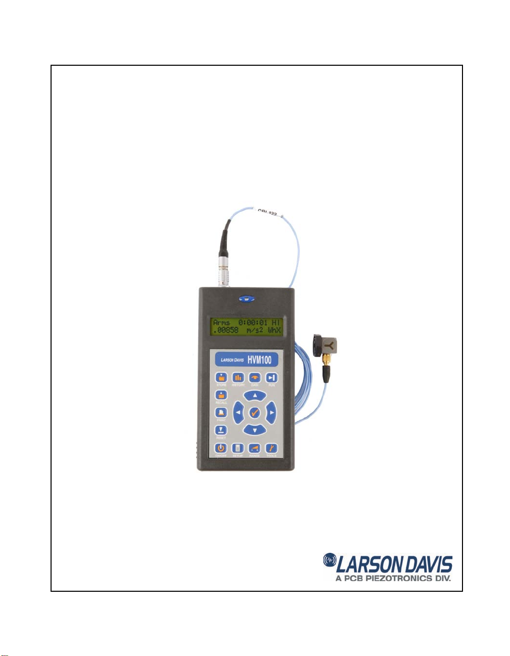
Thank you for purchasing the Human Vibration Meter from
Larson Davis. The HVM100 is a powerful but small vibration measurement tool. This Handheld vibration analyzer
will allow a variety of applications to be performed including; Whole Body Vibration analysis, Hand-Arm Vibration
analysis, and general purpose vibration analysis.
This full featured vibration analyzer features 3 input
channels, a sum channel, a variety of frequency weighting
and band limiting settings, single and double integration,
displayed data in a variety of units, and independent AC or
DC outputs for all 3 channels simultaneously.
We invite you to read this manual to obtain the best results
from your HVM100.
This manual has 9 chapters and 5 appendices covering the
following topics:
Chapter 1 - Introduction
In this chapter we will discuss the functionality and
capabilities of your HVM100. We will also go into detail
with regards to frequency weightings and screen and menu
functionality.
Chapter 2 - Getting Started
This chapter will describe in detail the functionality and
selections contained in the Setup menu.
Chapter 3 - The Tools Menu
This chapter will describe in detail the functionality and
selections contained in the Tools menu.
HVM100 Manual Introduction 1-1
Page 11

Chapter 4 - The Range Menu
This chapter will describe in detail the functionality and
selections contained in the Range menu. This includes
calibration of the HVM100.
Chapter 5 - Printing
This chapter will describe how to download data from the
HVM100.
Chapter 6 - Storing and Recalling Data File s and
Setups
This chapter will describe in detail how to store data and
setup information in the HVM100’s on-board memory.
Chapter 7 - Taking Measurements/Viewing Data on
the HVM100
This chapter will describe in detail how to use the Run/Stop
key to take measurements, and how to view that data on the
display of the HVM100.
Chapter 8 - Powering the HVM100
This chapter will describe the two ways in which to power
the HVM100.
Chapter 9 - Connections on the HVM100
This chapter will describe all of the external connectors on
the HVM100.
Chapter 10- Adaptor Resonances
This chapter will describe the frequency response function
data for the ADP08XA Adaptors.
Appendix A - Specifications
Appendix B - Glossary
Appendix C - I/O Commands
Appendix D - Frequency Response Curves
Appendix E - Miscellaneous Information
Appendix F - Serial Number Backup
1-2 HVM100 Manual
Page 12

Accessories
Standard Accessories
Optional Accessories
Selection of the proper accessories for use with your
HVM100 is one of the most important functions you can
perform. The transducer is especially critical to obtaining
good results.
The HVM100 is delivered with the following standard
accessories:
•User Manual
• Batteries, 2 x AA, IEC Type LR6
Transducers • SEN020 to SEN022 (Accel e rometers, 3 axis ICP
• SEN023 to SEN025 (Accel erometers, single axis ICP)
• SEN026 (3 axis ICP, palm accelerometer)
• SEN027 (Accelerometer, seat pad)
• SEN040F (Accelerometer, 3 axis, 2 - 5 kHz, ICP)
• SEN041F (Accelerometer, 3 axis, 2 - 5 kHz, ICP)
Calibrator • 394C06 (Hand-held accelerometer calibrator)
Cables • SEN020-CBL to SEN022-CBL (3 axis accelerometers
including cables)
• SEN023-CBL to SEN025-CBL (single axis
accelerometers including cables)
• SEN026-CBL (3 axis ICP,
cable)
• SEN027-CBL (Cable and seat pad accelerometer)
• SEN040F-CBL (Accelerometers, 3 axis, 2 - 5 kHz, ICP,
including cables)
• SEN041F-CBL (Accelerometers, 3 axis, 2 - 5 kHz, ICP,
including cables)
• CBL006 (Cable, serial computer, DB9S-mDIN08)
palm accelerometer including
)
HVM100 Manual 1-3
Page 13

• CBL120 (Cable, 3 x 10-32 male to 4-pin LEMO
female)
• CBL121 (cable, 3 x BNC male to 4-pin LEMO female)
• CBL124 (Cable, AC/DC Output, 3 X BNC to
Switchcraft
®
)
• CBL125 (Cable, Mini 4-pin to 4-pin LEMO female)
• CBL158 (Cable, 4-pin Microtech to 4-pin LEMO
Adaptors • ADP060 (Adapter, hand accelerometer)
• ADP061 (Adapter, handle accelerometer)
• ADP062 (Adapter, clamp accelerometer)
• ADP063 (Adaptor, palm accelerometer)
• ADP064 (HVM100 adapter kit)
• ADP080A (Adapter, hand accelerometer)
• ADP081A (Adapter, handle accelerometer)
• ADP082A (Adapter, clamp accelerometer)
• ADP084A (Vibration adaptor kit including ADP080A,
ADP081A, ADP082A and ADP063)
• 080A09 (Adapt or, probe tip with 10-32 connector)
• 080A17 (Adapt or, triaxial mounting)
• 080B16 (Adaptor, triaxial mounting, for SEN024 and
SEN025 with 5-40 thread)
®
male)
Cases • CCS020 (HVM100 hard shell carrying case)
• CCS028 (Soft case with belt clip fo r HVM100
Power Supply • PSA027 (Power supply, 90-264 VAC to 12 VDC)
Software • Blaze
®
software (SWW-BLAZE-HVM) for setup,
control and high speed data download
• HVManager software permits both users and
manufacturers of vibrating equipment to create PC-based
vibration data bases containing data measured using an
HVM100 Human Vibration Meter
• DNA (Data, Navigation and Analysis) software for
instrument control, high speed data download, data
streaming with real-time data display on PC, advanced
data graphic presentations and powerful report
generation features
1-4 HVM100 Manual
Page 14

• HVM Programmer software, available from Larson
Davis, can be used to programs the languages and update
the firmware when new versions are available for the
HVM100.
Selecting the Proper Transducer
There are several important considerations when selecting a
transducer to perform your measurements. The first decision
that must be made is what type of transducer to use.
NOTE: The HVM100 has built-in ICP
power supplies and charge amplifiers.
This will allow the HVM100 to interface
directly with ICP or charge transducers,
and eliminates the need for external signal conditioning.
There are two general categories of accelerometers, ICP
and Charge.
®
•ICP
accelerometers are also called “Voltage Mode” or
“Low impedance” and may be known by various other
vendor trade names. ICP is PCB’s registered trademark
which stands for “Integrated Circuit Piezoelectric” and
identifies PCB sensors which incorporate built-in, signal
conditioning electronics. The built-in electronics serve to
convert the high impedance charge signal that is
generated by the piezoelectric sensing element to a
usable low impedance voltage signal which can be
readily transmitted over ordinary 2 wire or coaxial cables
to any voltage readout or recording device. The low
impedance signal can be transmitted over long cable
distances and used in dirty field or factory environments
with little signal degradation.
®
• Charge mode sensors output a high impedance, electrical
charge signal that is generated by the piezoelectric
sensing element. This signal is extremely sensitive to
corruption from environmental influences. To conduct
accurate measurements, it is necessary to condition this
signal to a a low impedance voltage before it can be input
to a readout or recording device. A charge amplifier or
in-line charge converter is generally used for this
purpose.
®
The final way to use the input of the HVM100 is through the
direct input. This would require the use of some kind of
external signal conditioning unit such as an external source
of ICP power, or an external charge amplifier.
HVM100 Manual 1-5
Page 15

The next item to consider is the sensitivity of the transducer.
The sensitivity of the accelerometer will depend on the
application being performed. If the application is a high
vibration level application, a low sensitivity should be
selected. For low vibration level applications a high
sensitivity accelerometer should be used.
NOTE: Transverse sensitivity is also
something to be considered. Transverse
sensitivity is defined as: The unwanted
output signal of a motion sensor when
subjected to motion perpendicular to the
sensitive axis-usually expressed as a percent of the normal axis sensitivity. For
example if you are using a tri-axial
accelerometer and place an input signal
on the Z axis, your X axis could also be
reading a level even though there is
really no x-axis signal present.
The resonant frequency of the transducer should also be
considered. The resonant frequency is defined as the
frequency at which the structure will readily vibrate. For
accelerometers, there is one frequency where the
accelerometer will vibrate much easier than at other
frequencies. At this point, the reading will be very high, and
could overload the input of the HVM100. However, for most
of the recommended accelerometers, the resonant frequency
is well above the upper limit of the HVM100, and will
subsequently be masked out by the low pass filter on the
HVM100. If the resonant frequency becomes an issue, it is
recommended that an external mechanical filter be used.
Frequency range is the next thing to take into consideration.
Most recommended accelerometers will have a frequency
range sufficient for use with the HVM100. See the
frequency response tables (appendix A) and graphs
(appendix D) for more information on the HVM100’s
frequency response.
The last thing to consider is temperature, humidity, and other
physical agents, such as mounting surface, mass and
environment. The mass of the accelerometer should ideally
be no more that 1/50 of the mass of the object being
measured. A ratio of as little as 1/10 is acceptable in extreme
circumstances. The affect of these elements should always
be considered when choosing a transducer. Please also be
aware of the different methods of mounting an
accelerometer and the effects of each of those methods on
the measured data.
The following is a selection from the PCB catalog listing the
characteristics of a transducer. Please note the items that we
have discussed and note where they appear in a transducer
specification
1-6 HVM100 Manual
Page 16

Triaxial Accelerometers .
Specification Unit SEN020 SEN21F SEN026
Voltage Sensitivity mV/g 1 10 10
Frequency Range (+/-5%) Hz 0.5 to 5,000 0.5 to 2,500 1 to 9,000
Frequency Range (+/-10%) Hz 0.3 to 6,000 0.5 to 12,000
Mounted Resonant Frequency kHz 25 25 25
Measurement Range +/-g pk 1,500 500 500
Broadband Resolution (1 Hz to 10
kHz)
Shock Limit +/-g pk 7,000 7,000 10,000
Operating Temperature Range
Amplitude Linearity % +/1 +/1 +/1
Transverse Sensitivity % 5 5 5
Strain Sensitivity g/ 0.001 0.001
Excitation Voltage VDC 20 to 30 20 to 30 18 to 30
Constant Current mA 2 to 20 2 to 20 2 to 20
Output Impedance ohms <100 <100 <200
Output Bias VDC 8 to 12 8 to 12 7 to 11
Discharge Time Constant sec 1.0 to 2.0 .4 to 1.2 1.0 to 3.5
Sensing Element Type Ceramic Ceramic Ceramic
Element Configuration Structure Shear Shear Shear
Electrical Connector type/location 4-Pin/side 4-Pin/side 4-Pin/side
Housing material/sealing Titanium/Hermetic Titanium/Hermetic Titanium/Hermetic
Mounting Thread size 10-32 Female 5-40 Male 10-32 Female
g rms 0.005 0.0005 0.0002
o
F [oC] -65 to +250 [-54 to
+121]
-65 to +250 [-54 to
+121]
-65 to +250 [-54 to
+121]
HVM100 Manual 1-7
Page 17

.
Specification Unit SEN027 SEN040F SEN041F
Voltage Sensitivity mV/g 100 1 10
Frequency Range (+/-5%) Hz 0.5 to 1,000 2 to 4,000 2 to 4,000
Frequency Range (+/-10%) Hz
Mounted Resonant Frequency kHz 27 55 55
Measurement Range +/-g pk 10 5,000 500
Broadband Resolution (1 Hz to 10
kHz)
Shock Limit +/-g pk 2,000 10,000 10,000
Operating Temperature Range
Amplitude Linearity % +/1 +/2.5 +/1
Transverse Sensitivity % 5 5 5
Strain Sensitivity g/
Excitation Voltage VDC 6.5 to 30 18 to 30 18 to 30
Constant Current mA 0.3 to 10 2 to 20 2 to 20
Output Impedance ohms <500 <200 <200
Output Bias VDC 2.8 to 4.5 7 to 11 7 to 11
Discharge Time Constant sec 1.0 to 3.0 1.5 to 3.0 .3 to 1.0
Sensing Element Type Ceramic Ceramic Ceramic
Element Configuration Structure Shear Shear Shear
Electrical Connector type/location Integral cable/side 1/4-28 4-Pin/side 1/4-28 4-Pin/side
Housing material/sealing Titanium/Hermetic Titanium/Hermetic Titanium/Hermetic
Mounting Thread size 10-32 Female 5-40 Female 5-40 Female
g rms 0.002 0.03 0.008
o
F [oC] +14 to +122 [-10 to
+50]
-65 to +250 [-54 to
+121]
-65 to +250 [-54 to
+121]
1-8 HVM100 Manual
Page 18

Single Axis Accelerometers .
Specification Unit SEN022 SEN024 SEN025
Voltage Sensitivity mV/g 100 10 10
Frequency Range (+/-5%) Hz 0.5 to 5,000 1 to12,000 1 to 10,000
Frequency Range (+/-10%) Hz 0.3 to 6,000 0.7 to 18,000 0.3 to 12,000
Mounted Resonant Frequency kHz 25 50 35
Measurement Range +/-g pk 50 500 50
Broadband Resolution (1 Hz to 10
kHz)
Shock Limit +/-g pk 7,000 10,000 5000
Operating Temperature Range
Amplitude Linearity % +/1 +/1 +/1
Transverse Sensitivity % 5 5 5
Strain Sensitivity g/ 0.001 0.006 0.005
Excitation Voltage VDC 20 to 30 1 to 30 1 to 30
Constant Current mA 2 to 20 2 to 20 2 to 20
Output Impedance ohms <200 <100 <300
Output Bias VDC 8 to 12 8 to 12 8 to 12
Discharge Time Constant sec 1 to 3 .4 to 1.2 .4 to 1.2
Sensing Element Type Ceramic Ceramic Ceramic
Element Configuration Structure Shear Shear Shear
Electrical Connector type/location 4-Pin/side 10-32 10-32
Housing material/sealing Aluminum/Epoxy Titanium/Hermetic Titanium/Hermetic
Mounting Thread size 10-32 Male 5-40 Male 5-40 Male
g rms 0.0001 0.0005 .00016
o
F [oC] -65 to +176 [-54 to
+80]
-65 to +250 [-54 to
+121]
-65 to +200 [-54 to
+93]
About the HVM100
The HVM100 is a powerful, all digital, vibration analyzer. It
features simultaneous 3 channel measurements, small
lightweight design, easy to read display, portability utilizing
2 AA batteries, 115.2 kbps RS-232 interface, three modes of
HVM100 Manual 1-9
Page 19

operation: Hand-Arm, Whole Body, and Vibration, and the
capability to display and print text in a variety of languages.
Modes of Operation
The HVM100 is divided into three modes of operation. The
standard mode is the vibration mode. This is the mode
included with the instrument. The other two modes are
optional modes. The Optional modes are Hand-Arm and
Whole Body. Each of these modes feature different
frequency weighting selections as outlined later in this
chapter.
Frequency Weighting Selections
NOTE: The Hand-Arm and Whole body
modes are separately purchased options.
These options and the frequency weightings associated with these options will
not be available unless they are purchased.
Mode Frequency Weighting
Vibration Ws (Severity)
Hand Arm W
Whole Body W
To accommodate the multiple operating modes of the
HVM100, 13 different frequency weighting filters are
available. The following table describes the frequency
weighting options available in each of the operating modes.
To select the frequency w eighting for a particular m ode, see
the section in this manual titled Setup Key.
Fa (0.4 Hz to 100 Hz)
Fb (0.4 Hz to 1250 Hz)
Fc (6.3 Hz to 1250 Hz)
h
m
W
b
W
c
W
d
W
e
W
g
W
j
W
k
The Hand-Arm mode and the Whole body mode frequency
weighting curves are defined in ISO 8041:2005. The W
1-10 HVM100 Manual
g
Page 20

Band Limiting Filters
frequency weighting curve is defined in British Standard
6841:1987.
In addition to defining the frequency weightings for HandArm and Whole Body, ISO 8041:2005 also defines a bandlimiting filter to be used with each of the frequency
weightings. Each band-limiting filter is a combination of a
high-pass and low-pass 2nd order Butterworth filter, 12 dB
per octave attenuation, with - 3 dB corner frequencies at the
frequencies listed in table 3 below. When a frequency
weighting is selected in the HVM100 Hand-Arm mode, or
Whole Body mode, the HVM100 automatically places both
the weighting filter and the appropriate band-limiting filter
in the signal path.
Weighting Band-Limiting Filter
W
h
W
m,Wc, Wd, We, Wj, Wk
, Wg 0.8 to 100 Hz
W
m
6.3 to 1250 Hz
0.4 to 100 Hz
HVM100 Manual 1-11
Page 21

1-12 HVM100 Manual
Page 22
CHAPTER
On Key
Getting Started
2
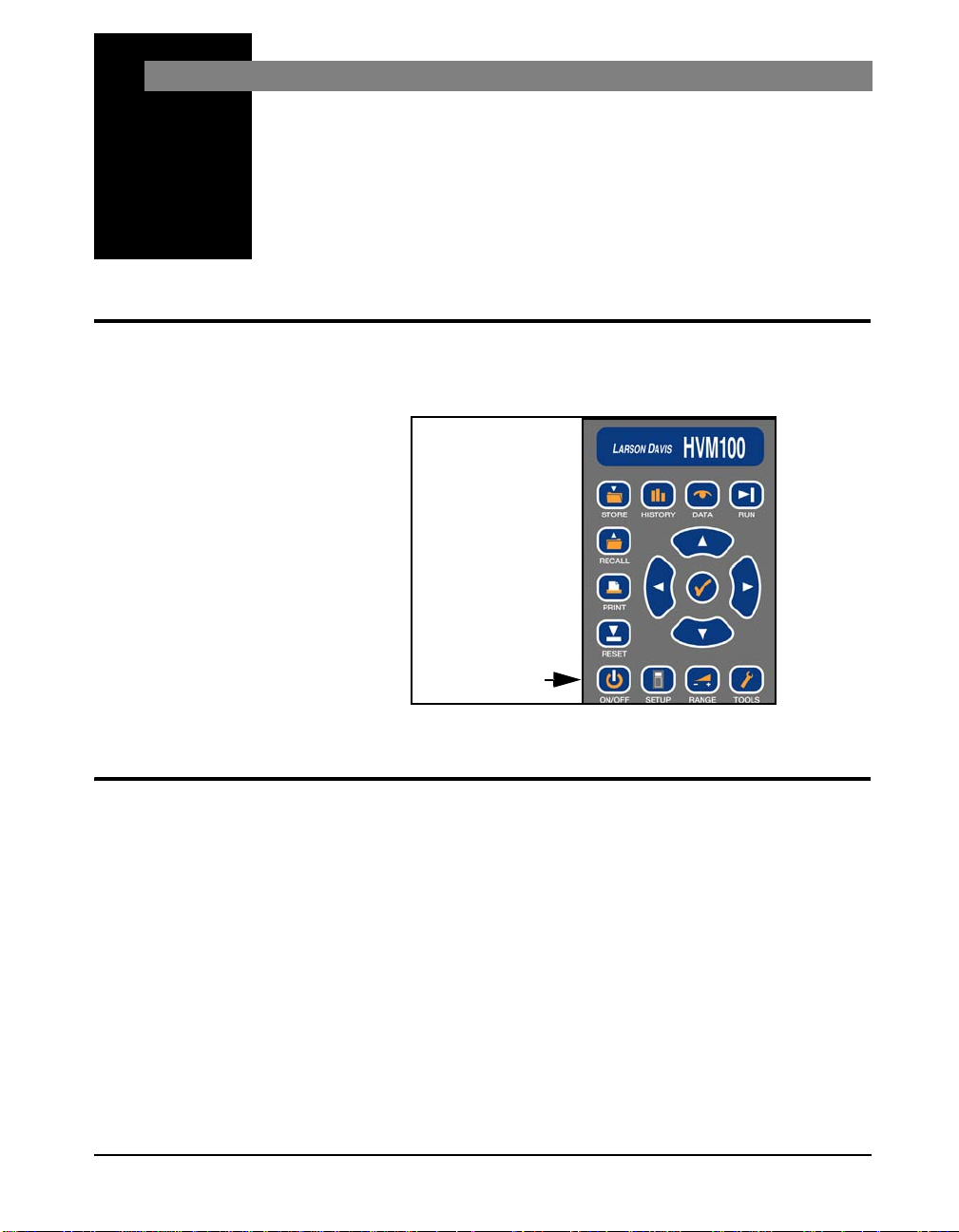
Switching HVM100 On
This section will introduce you to the keypad and
functionality of the HVM100.
If any displays appear during the
boot process which refer to Serial
Number or SN, see section "Serial
Number Backup" on page F-1.
Menu Navigation
To swit ch the HVM100 On, press the On key.
Navigating through the HVM100 menus is similar to
navigating through other Larson Davis instruments. The
menus are arranged in lists. The appropriate menu key is
used to enter the menu, and then the u Up and d Down
arrow keys are used to scroll through the menu. When you
come to a setting you want to change, press the c Check
key to enter the modify section of the menu. You can now
use the r Right and l Left arrow keys to scroll th rough
the options for that item. After the appropriate selection is in
the window, use the c Check key to select that setting. This
will place you back into the main menu where once again
the u Up and d Down arrow keys can be used to
navigate.
HVM100 Manual Getting Started 2-1
Page 23

Alpha Numeric Menu Function
The alpha numeric menu screens include the Header screens
and the Calibrator sensitivity screen. These are settings that
require the user to enter letters of the alphabet or numerals
into the field. To change an alpha numeric menu setting,
Step 1 Go to the menu item you wish to change.
Header 1
Step 2 Press the c key to place the HVM100 into the
modify mode. The selection will begin to blink.
Header 1
Step 3 Use the r and l arrow keys to select a posi-
tion to modify.
Header 1
Step 4 Use the u and d arrow keys to select the char-
acter you want in that position.
Header 1
Wi
Step 5 Use the rand l arrow keys again to move to
the next position. When you move to the next
position, the HVM100 will start you from where
you left off. (i.e. if you entered an ‘F’ in the first
position, when you move to the next position, you
will be starting from the ‘F’ on that position.
Header 1
Wil
Step 6 Hit the c key or move to the next menu item to
accept the change. Anytime you have made a
change, the change will automatically be accepted
2-2 Menu Navigation HVM100 Manual
Page 24

Indexed Menu Function
even if you don’t hit the check key . You can accept
the change just by moving to another section of
the HVM100.
Header 1
Wilson Processin
The following is an example of how to make a change to an
indexed menu item. (An item that has a specific list of
choices.)
Step 1 Go to the setting you wish to change.
Operating Mode
Vibration
Step 2 Press the c key to place the HVM100 in the mod-
ify mode. The selection will begin to blink.
Operating Mode
Vibration
Step 3 Use the l and r arrow keys to scroll through
the selections in the menu.
Operating Mode
Vibration
r
Operating Mode
Hand Arm
r
Operating Mode
whole Body
Step 4 When you come to the selection you desire, stop
scrolling.
Operating Mode
Whole Body
HVM100 Manual Menu Navigation 2-3
Page 25
Key Board Functions
Step 5 To accept the change, either hit the c key or move
to the next menu item or to another part of the
HVM100.
Operating Mode
Whole Body
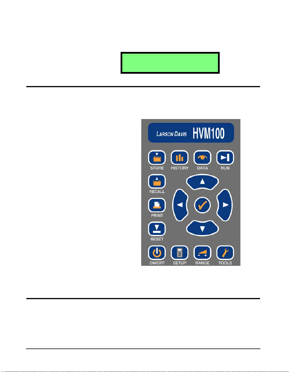
The keyboard on the front of the HVM100 is the main
interface to the instrument. The keyboard consists of 11
dedicated function keys, 4 arrow keys and the check key.
In the following section, we will describe the functionality
and selections associated with each key.
Setup Key
The SETUP key places you into the Setup menu. This menu
is used to set general system parameters such as operating
mode and frequency weighting. The selections available in
the Setup menu are described below. The Setup menu is a
2-4 Key Board Functions HVM100 Manual
Page 26

Mode Selection
Hint: This setting is in the Setup menu. To access the Setup menu press the
SETUP key and then use the u and d arrow keys to navigate
through the menu items.
NOTE: To view each selection, first pr ess
c key, and then press the r or l
the
arrow key to scroll through each selection.
circular menu. You can scroll through and return to the top
by continuously pressing the d or u arrow key.
NOTE: T he Hand-Arm and Whole body
modes are separate purchased options.
These options and the frequency weightings associated with those options will
not be available unless they are purchased.
Averaging Ti me
Hint: This setting is in the Setup menu. To access the Setup menu press the
SETUP key and then use the u and d arrow keys to navigate
through the menu items.
This section is used to set the operating mode. The
selections are Whole body, Hand Arm or Vibration.
Operating Mode
Vibration
Operating Mode
Hand Arm
Operating Mode
Whole Body
HVM100 Manual Setup Key 2-5
Page 27

NOTE: An exponential detector is
defined as a detector that maintains a
moving average of the signal. The only
exponential detector in the HVM100 is
the Slow detector. This detector will
begin by taking a 1 second average. As
time moves, the exponential detector will
discard the first part of the average, as
the next part is collected. A linear detector will take the signal and average over
the averaging time, and then start over.
All previously collected samples are disregar ded in the new linear average.
Time History Settings The Averaging time is also used to determine the rate of
The averaging time refers to the amount of time data is
collected and averaged before a new average is started. The
selections are Slow, 1 sec, 2 sec, 5 sec, 10 sec, 20 sec, 30
sec, and 60 sec. The Slow response is a 1 second exponential
detector, while the others are linear repeat type averages.
The averaging is the same for all Operating modes.
storage for the Time History. The Time History will store the
Arms value along with the Peak value if the user desires, for
the X, Y, Z, and Sum channels. The Time History buffer is
limited to 240 samples, 120 samples if the Peak value is
selected. To setup Time History Peak storage, see the 2nd
History menu section below.
NOTE: T o view each selection, first press
the c key, and then press the r or l
arrow key to scroll through each selection.
The following are the selections you would encounter when
changing the Averaging Time:
Averaging
Slow
Averaging
1 sec
Averaging
2sec
Averaging
5 sec
Averaging
10 sec
Averaging
20 sec
2-6 Setup Key HVM100 Manual
Page 28

Store Time
Averaging
30 sec
Averaging
60 sec
Hint: This setting is in the Setup menu. To access the Setup menu press the
SETUP key and then use the u and d arrow keys to navigate
through the menu items.
NOTE: To change the Store Time parameters, press the
d
arrows to select the desired value,
and then use the r and l arrows
to move to the next position. Once all
positions are set press the
move to any other part of the HVM100 to
accept the entry.
c key, use the u and
c key or
Auto Store
Hint: This setting is in the Setup menu. To access the Setup menu press the
SETUP key and then use the u and d arrow keys to navigate
through the menu items.
NOTE: The data memory in the HVM100
is a non-volatile EEPROM chip. Even if
the batteries go dead for an extended
period of time, the stored setups and data
will be retained.
The Store Time selection works in conjunction with the
Auto Store setting. The Auto Store setting will allow you to
automatically store measurement data at a rate indicated by
the Store Time. The Store Time can be set from 1 minute to
99 hours.
Store Time hh:mm
00:00
The Auto Store function in the HVM100 will allow you to
store data over time. The Store Time is the rate at which the
data will be stored. At the end of the store time the Auto
Store function will store any history data that has been
collected, as well as the overall data from all three channels
and the sum channel. The data will be stored as a file in the
memory. After the data is stored, the instrument is reset
automatically and a new set of data is collected. The
limitation on the memory is 100 files. When the memory
reaches the maximum number of files, it will stop storing
data.
NOTE: To view each selection, first pr ess
the c key, and then press the r or l
arrow key to scroll through each selection.
HVM100 Manual Setup Key 2-7
There are three selections in the Auto Store menu:
Auto Store
Off
Page 29

2nd History
The Auto Store is turned off with this setting.
Auto Store
On
The Auto Store feature will store each time the Store T ime is
reached. This will continue until all file registers are full.
Auto Store
Autostop
The Auto Store-Autostop feature will allow you to take a
fixed length measurement. The Autostop feature will stop
the meter when the Store time is reached, just as if you had
pressed the s key.
Hint: This setting is in the Setup menu. To access the Setup menu press the
SETUP key and then use the u and d arrow keys to navigate
through the menu items.
The 2nd History setting will allow you to store a Peak value
along with the Arms value that is automatically stored in the
Time History buffer. The Peak will be stored for all three
channels and the Sum channel. Turning on the 2nd value
will cut the number of sample storage space from 240
samples to 120 samples.
NOTE: T o view each selection, first press
the c key, and then press the r or l
arrow key to scroll through each selection.
In the 2nd history selection menu you have the choice of
None or Peak.
2nd history
None
2nd History
Peak
Vibration Mode Weighting
Hint: This setting is in the Setup menu. To access the Setup menu press the
SETUP key and then use the u and d arrow keys to navigate
through the menu items.
2-8 Vibration Mode W eighting HVM100 Manual
Page 30

NOTE: To view each selection, first pr ess
the c key, and then press the r or l
arrow key to scroll through each selection.
In the vibration mode you can select from the following
weighting selections. Please see the appendix at the end of
this manual for details on weighting curves. The weighting
selection is independent for all channels. Here we only
depict the X channel data, but the other channels screens
would be the same:
Weighting X
Fa 0.4-100 Hz
Weighting X
Fb 0.4-1250 Hz
Weighting X
Fc 6.3-1250 Hz
Weighting X
Ws Severity
Hand Arm Mode Weighting
As required by ISO 8041:2005 the Hand Arm mode has only
one weighting selection. Please see the appendix at the end
of this manual for details on this weighting curve. The
weighting curve is labeled as Wh. This weighting selection
is for all channels and the sum channel. Because there is
only one selection in the Hand Arm mode, the weighting
selection is not present on the Setup menu.
Whole Body Weighting Mode
Hint: This setting is in the Setup menu. To access the Setup menu press the
SETUP key and then use the u and d arrow keys to navigate
through the menu items.
NOTE: To view each selection, first pr ess
c key, and then press the r or l
the
arrow key to scroll through each selection.
HVM100 Manual Hand Arm Mode Weighting 2-9
In the Whole Body mode you can select from the following
weighting selections as required by ISO8041:2005. Please
see the appendix at the end of this manual for details on the
weighting curves. The weighting selection is independent
Page 31

for all channels. Here we only depict the X channel data, but
the other channels screens would be the same:
Weighting X
Wm
Weighting X
Wb
Weighting X
Wc
Weighting X
Wd
Weighting X
We
NOTE: The Wg frequency weighting
curve is defined in BS 6841:1987.
Weighting X
Wg
Weighting X
Wj
Weighting X
Wk
2-10 Whole Body W eighting Mode HVM100 Manual
Page 32

CHAPTER
3
Tools Key
Accelerometer
Tools Menu
The Tools menu has settings relating to the transducer and
setup information relevant to the instrument. Selections
include communications, printing, headers, etc.
The tools menu functions in exactly the same manner as the
Setup menu and has the following selections:
Hint: This setting is in the Tools menu. To access the Tools menu press the
TOOLS key and then use the u and d arrow keys to navigate
through the menu items.
NOTE: To view each selection, first pr ess
the c key, and then press the r or l
arrow key to scroll through each selection.
This will allow you to select the type of transducer you wish
to use. The selections are ICP
refer to the type of accelerometer being used.
®
, Direct, and Charge. These
Accelerometer
Direct
The Direct setting is used to input a direct signal from a
transducer. No operational power is provided to the
transducer.
Accelerometer
XDC=10.0V
ICP
®
The ICP
to each of the three input channels, in order to power up to
three accelerometers. This is used with ICP type
accelerometers. The voltage reported on this screen is a
monitoring of the ICP power being provided to the
HVM100 Manual Tools Menu 3-1
setting will pr ovid e a 28 Volt 2mA constant current
Page 33

transducer. When the transducer is not connected, this
voltage will read 25 to 26 volts. If you have a transducer
connected and it is working properly, it should be reading
between 2 and 12 volts depending upon the transducer.
Accelerometers
Display Units
The following table shows the typical bias voltage for the
various ICP
®
accelerometers that are normally used with the
HVM100.
Tri-Axial
SEN020
SEN022
Single Axis
Accelerometers
SEN023
SEN024
Palm-Adapter
Accelerometer
SEN026
Seat Pad
Accelerometer
SEN027
SEN025
8-12 volts 8-12 volts 7-11 volts 2-5 volts
®
If the reading is 0, then the ICP
power could be shorted to
ground or have some other problem. Check all connections,
cables, and connectors.
Accelerometer
Charge
This setting would be used to amplify the signal from a
charge type accelerometer.
Hint: This setting is in the Tools menu. To access the Tools menu press the
TOOLS key and then use the u and d arrow keys to navigate
through the menu items.
NOTE: T o view each selection, first press
the c key, and then press the r or l
arrow key to scroll through each selection.
3-2 Tools Key HVM100 Manual
The Display Units setting controls how data is displayed and
printed by the HVM100. The HVM100 can display data in
six different formats. The selection of the display units will
apply to all three channels and the sum channel. All
channels will have the same units. The choices ar e: m/s
2
, ft/s2, in/s2, g, and dB.
s
2
, cm/
Page 34

NOTE: The HVM100 uses a reference
acceleration of 10-6 m/s2 (velocity reference = 10
= 10
(velocity reference = 10-8 m/s, displacement reference = 10
acceleration, velocity and displacement
in dB units. Please see the section in the
RANGE key for details on changing the
reference acceleration.
-9
m/s, displacement reference
-12
m) or a reference of 10-5 m/s
-11
m) to display
Integration
Hint: This setting is in the Tools menu. To access the Tools menu press the
TOOLS key and then use the u and d arrow keys to navigate
through the menu items.
Display Units
2
m/s
2
Display Units
cm/s
2
Display Units
ft/s
2
Display Units
in/s
2
Display Units
g
Display Units
dB
NOTE: Integration is a mathematical
process of changing the displayed units
from acceleration to velocity to displacement. Single integration changes the displayed parameter from acceleration to
velocity by dividing the acceleration
2f (i.e. ft/s
by:
tion changes the parameter from acceleration to displacement by dividing the
acceleration by:
meters).
2
to ft/s). Double integra-
2
42f
(i.e. m/s2 to
Integration applies only to the Vibration mode. There is no
integration available in the Hand Arm or Whole Body
Modes. Integration is the process of converting the data
from acceleration, which is the standard method of
displaying the data, into velocity and displacement.
Integration
None
Integration
Single
Integration
Double
HVM100 Manual Tools Key 3-3
Page 35

NOTE: T o view each selection, first press
the c key, and then press the r or l
arrow key to scroll through each selection.
Sum Factor X,Y, Z
Hint: This setting is in the Tools menu. To access the Tools menu press the
TOOLS key and then use the u and d arrow keys to navigate
through the menu items.
Single integration will express the units in velocity, and
double integration will express the units in displacement.
In the process of calculating the sum quantities (the data
that appears under the
menu) the HVM100 multiplies the
instantaneous acceleration for each channel by a scaler
factor (sometimes called a k-factor). The HVM100 allows
the user to select a different k factor for each channel. The
default setting is 1.00; however; some applications may
require different settings.
Sum Factor X
1.00
NOTE: To change the Sum Factor
parameter, press the c key, use the u
and d
value, and then use the r and l
arrow
Once all positions are set press the
key
HVM100 to accept the entry.
arrows to select the desired
s to move to the next position.
or move to any other part of the
The applications that require the Sum Factor to be altered
are specified in certain ISO standards. If you are not trying
to measure according to any specific standard, the
appropriate setting for this parameter is 1.00.
c
Quantities affected by sum factors ar e A
, Peak, PE and VDV. Individual axis data is not affected.
A
eq
rms
, A
min
, A
max
, Amp,
AC/DC Output
Hint: This setting is in the Tools menu. To access the Tools menu press the
TOOLS key and thenuse the u and d arrow keys to navigate
through the menu items.
The AC/DC outputs on the HVM100 are independent and
simultaneous for all three channels. First we will discuss the
output in general, and then give the specific settings f or the
AC/DC outputs.
3-4 Tools Key HVM100 Manual
Page 36

NOTE: To view each selection, first pr ess
Example: Chart recorder output, monitoring the
DC output, with an averaging time of 60 seconds.
the c key, and then press the r or l
arrow key to scroll through each selection.
AC output is useful for frequency analysis by an external
analyzer or for recording in a tape recorder. The DC output
is useful for a chart recorder, or to measure the voltage
proportional to the RMS or peak value.
The DC output is updated according to the averaging time.
If the averaging time is set to slow, the signal on the DC
output pin for the selected channel will be updated once p er
second. If the averaging time is set to 60 seconds, the signal
on the DC output pin for the selected channel will be
updated once every 60 seconds.
The AC/DC output connector is a 5 pin Switchcraft
connector located on the bottom edge of the instrument. The
pinout is as follows:
®
HVM100 Manual Tools Key 3-5
Page 37

3
4
1
2
5
Pin # Description
1 Ground
2 X - Axis AC/DC Output
3 Y - Axis AC/DC Output
4 No Connection
5 Z - Axis AC/DC Output
The signal that is output on each pin is selectable for each
channel. The selections are the same for each channel. We
will list the X channel selections, however the available
selections will be the same for all operating modes as well.
3-6 Tools Key HVM100 Manual
The AC output will produce a signal from 0 - 0.5 Volt RMS.
The scale of the DC output is typically 5 mV/dB. The level
Typically varies between 0 Vdc to +1.0 Vdc.
Page 38

AC/DC Output Settings
AC/DC Output X
AC: Weighted
AC/DC Output X
AC: BandLimit
AC/DC Output X
DC: rms
AC/DC Output X
DC: min
AC/DC Output X
DC: max
AC/DC Output X
DC: peak
AC/DC Output X
DC: rms
AC/DC Output X
DC: min
AC/DC Output X
DC: max
AC/DC Output X
DC: peak
The weighting filters work in
conjunction with the band limiting
filters. See page 1-7.
Setting Description
AC:
Weighted
AC: BandLimit
DC: rms
DC: min
DC: max
DC: peak
DC: rms
DC: min
DC: max
DC: peak
This will weight the output pin for the selected
channel according to the weighting selected
for that channel. If Channel X has a weighting
of Ws, then the output pin for Channel X will
produce a Ws weighted AC signal.
This will weight the output pin for the selected
channel according to the Band Limiting filter,
specified in chapter 1, for that channel. For
example if Channel X has a weighting of Wh,
then the output pin for Channel X will produce
a band limited (6.3 to 1250 Hz) AC signal.
This signal will be a DC voltage with a level
proportional to the RMS level displayed on the
HVM100.
This signal will be a DC voltage with a level
proportional to the min level displayed on the
HVM100.
This signal will be a DC voltage with a level
proportional to the max level displayed on the
HVM100.
This signal will be a DC voltage with a level
proportional to the peak level displayed on the
HVM100.
This signal will be a DC voltage with a level
proportional to the RMS sum level displayed
on the HVM100.
This signal will be a DC voltage with a level
proportional to the min sum level displayed on
the HVM100.
This signal will be a DC voltage with a level
proportional to the max sum level displayed on
the HVM100.
This signal will be a DC voltage with a level
proportional to the peak sum level displayed
on the HVM100.
HVM100 Manual Tools Key 3-7
Page 39

Baud Rate
Only one selection can be made for each channel. Channels
Y and Z will have the same selection of settings. The
weighting selected can be independent for each channel.
Hint: This setting is in the Tools menu. To access the Tools menu press the
TOOLS key and then use the u and d arrow keys to navigate
through the menu items.
The Baud rate selection will allow you to communicate with
the PC or the serial printer. The choices are as follows:
Baud Rate
2400
Baud Rate
9600
Baud Rate
38.4k
Baud Rate
115.2k
NOTE: T o view each selection, first press
c key, and then press the r or l
the
arrow key to scroll through each selection.
Handshaking The handshaking on the HVM10 0 is defaulted to hardware
It is important that the setting on your computer or on the
serial printer match the Baud Rate setting of the HVM100.
(DTR) handshaking.
Print History Selection
Hint: This setting is in the Tools menu. To access the Tools menu press the
TOOLS key and then use the u and d arrow keys to navigate
through the menu items.
3-8 Tools Key HVM100 Manual
Page 40

The print history selection will determine whether or not the
HVM100 will send the History Buffer information when the
PRINT key is pressed.
Print History
Yes
NOTE: To view each selection, first pr ess
the c key, and then press the r or l
arrow key to scroll through each selection.
Erase All Files
Hint: This setting is in the Tools menu. To access the Tools menu press the
TOOLS key and then use the u and d arrow keys to navigate
through the menu items.
This selection will cause the HVM100 to send data
contained in the History buffer to the printer.
Print History
No
With this selection, the HVM will only send the overall data
from the 3 input channels and the sum channel.
This allows you to clear the measurement files from the
memory of the HVM100. The memory in the HVM100 is a
non-volatile memory. If the batteries go dead, the
measurement files will not be lost. The only way to clear out
the file registers is to use the Erase All files menu.
This command will not clear the current measurement, or
the current history buffer information. The R Reset key is
used for that purpose. This command will only clear the file
registers.
To clear all files:
NOTE: To view each selection, first pr ess
the c key, and then press the r or l
arrow key to scroll through each selection.
Step 1 Go to the Erase All Files menu item.
Step 2 The following screen will appear. Press the c key.
The ‘No’ will start to flash. Press the r key to
change the screen to ‘Yes’.
Erase All Files
No
HVM100 Manual Tools Key 3-9
Page 41

Erase Setups
Step 3 The following screen will now be showing and
the’Yes’ will be flashing. Press the c key to erase
the files.
Erase All Files
Yes
Step 4 After pressing the c key, the screen will display
the following message. After about 3 seconds the
display will return to the Erase All Files screen.
All Erased
Erase All Files
No
All file registers have now been cleared.
Hint: This setting is in the Tools menu. To access the Tools menu press the
TOOLS key and then use the u and d arrow keys to navigate
through the menu items.
The HVM100 has the ability to store 10 setups internally in
the memory. This is accomplished, as explained later in the
manual, by pressing the STORE key while in the setup
menu. The Erase Setups command is used to clear all of the
stored setups from the setup registers.
To clear all setups:
NOTE: T o view each selection, first press
the c key, and then press the r or l
arrow key to scroll through each selection.
Step 1 Go to the Erase Setups menu item.
Step 2 The following screen will appear. Press the c key .
The ‘No’ will start to flash. Press the r key to
change the screen to ‘Yes’.
Erase Setups
No
3-10 Tools Key HVM100 Manual
Page 42

Header 1,2,3
Step 3 The following screen will now be showing and the
‘Y es’ will be flashing. Press the c key to erase the
setups.
Erase Setups
Yes
Step 4 After pressing the c key, the screen displays the
following message. The display will return to the
Erase Setups screen after about 3 to 10 seconds.
All Erased
Erase Setups
No
All Setups have now been cleared from the setup registers.
Hint: This setting is in the Tools menu. To access the Tools menu press the
TOOLS key and then use the u and d arrow to navigate through
the menu items.
The HVM100 has 3 Heading information screens. This will
allow you to enter descriptive information into the
instrument, that will then be printed out with the reports.
The information can be up to 16 characters in length in each
screen.
To enter information in the Header screens, follow these
directions:
NOTE: To change the Header, press the
c key, use the u and d arrows to
select the desired value, and then use the
r and l arrows to move to the
next position. Once all positions are set
press the c key or move to any other
part of the HVM100 to accept the entry.
Step 1 Go to the Header that you wish to change.
Header 1
Step 2 You will have either a blank screen, or a screen
that has previously entered information.
Header 1
HVM100 Manual Tools Key 3-11
Page 43

Header 1
Wilson Processin
Hint: You can use the reset key to erase all of the existing entries in an alpha-
numeric entry. Position the cursor on the Left most position you want
erased. Press the R key, and all positions to the right of the cursor,
including the cursor position will be erased. If the cursor position is all
the way to the left, the entire screen will be erased.
NOTE: The HVM100 will remember the
previously selected character as you
move positions. If you enter a ‘K’ in the
1st position, when you use the r or l
arrow key to move the next position, you
will begin from the ‘K’.
Language
Hint: This setting is in the Tools menu. To access the Tools menu press the
TOOLS key and then use the u and d arrow keys to navigate
through the menu items.
NOTE: T o view each selection, first press
the c key, and then press the r or l
arrow key to scroll through each selection.
The HVM100 can only store four
different languages at one time.
Contact The HVM Programmer
software can be used to used select
and load these languages.
Step 3 Use the l and r arrow keys to select the posi-
tion you want to change, and use the u and d
arrow keys to change the character in that position.
Step 4 When you have completed all the entries, press the
c key to return to the Tools menu. You can now
move onto the next header (Header 2) by pressing
the arrow key.
The HVM100 has the ability to display and print in several
different languages. The choices are English, Spanish,
Italian, French, German, Portuguese, Czech, and Dutch.
Below is an example of one of the language options:
Language
English
Idioma
Espanol
Idioma
Italiano
Langage
Francais
3-12 Tools Key HVM100 Manual
Page 44

Date and Time
Hint: This setting is in the Tools menu. To access the Tools menu press the
TOOLS key and then use the u and d arrow keys to navigate
through the menu items.
NOTE: To change the Date and Time
parameter, press the c key, use the u
and d
value, and then use the
arrow
Once all positions are set press the c
key
HVM100 to accept the entry.
arrows to select the desired
r and l
s to move to the next position.
or move to any other part of the
The date and time functions can be set in this menu. To set
the date and time, go to this menu item. Press the c key . You
can now make changes just like the alphanumeric menu
items in the Header screens. Once all changes have been
made, press the c key again to confirm the changes.
Date
00:00 01 Jan 99
HVM100 Manual Tools Key 3-13
Page 45

3-14 Tools Key HVM100 Manual
Page 46

CHAPTER
4
Range Key
Auto Range
Range Menu
The RANGE key functi ons are concerned with the level of
input signals coming into the HVM100.
In this menu, Gain is added, Calibration is performed, AutoRanging is enabled, and Accelerometer Sensitivity is
entered.
Hint: This setting is in the Range menu. To access the Range menu press the
RANGE key and then use the u and d arrow keys to navigate
through the menu items.
The Auto-Range function in the HVM100 is designed to
work with a steady state signal, i.e. an object which is
vibrating at or near the level of your test object. Often this is
the object or subject under test. It should be used prior to
starting the actual measurement in order to optimize the
input levels from each of the three axes of the transducer’s
output based on actual vibration levels being produced by
the object or subject under test. It is not meant for use while
taking data. Before enabling this function, the transducer
should be attached to the steady state vibration source to be
measured. Next, find the Auto-Range display, located in the
Range menu. Press the c key to enable auto-ranging. The
HVM100 will use its Auto-Range algorithm to adjust the
gain for all three channels such that the steady state input
signal can be properly measured by the HVM100. (The gain
is adjusted so that the signal falls within the top 20 dB of the
HVM100’s analog to digital converter’s range.)
Auto-Range
X= 0 Y= 0 Z= 0
The selections for the gain will be either 0, 20, 40, or 60 dB.
HVM100 Manual Range Menu 4-1
Page 47

Gain X, Y, Z
Once the gain selection is stable, press the c key to save the
settings. The HVM100 must be stopped and reset before the
Auto-Range function can be used.
Hint: This setting is in the Range menu. To access the Range menu press the
RANGE key and then use the u and d arrow keys to navigate
through the menu items.
A very efficient way to manually set
the gain is to have the transducer
mounted on the subject under test, as
described in the section Auto Range
on page 4-1, and check for
indications of either under-range,
described in the section UnderRange Indicator (?) on page 7-2, or
overload, described in the section
Overload Detection on page 7-1,
and manually adjust the gain as
necessary to avoid both.
NOTE: T o view each selection, first press
c key, and then press the r or l
the
arrow key to scroll through each selection.
The Gain settings in the HVM100 will perform manually
what the Auto-Range setting did automatically.
You can select one channel at a time, and manually assign a
gain setting to that channel. The choices are 0, 20, 40, or 60
dB.
To set the Gain for the X channel, first press the RANGE
key to open the Range menu. Next press the d arrow key
once to view the Gain X parameter. Press the u and d to
enter the change mode, use the r or l arrow keys to
select the desired value, and press the c key again to
confirm the change. The Gain Y and Gain Z displays are
located just below the Gain X display. (From the Gain X
display press the d arrow key once to view the Gain Y
display. Press the d arrow key again to view the Gain Z
display.)
Gain X
40 dB
Cal Level
Hint: This setting is in the Range menu. To access the Range menu press the
RANGE key and then use the u and d arrow keys to navigate
through the menu items.
4-2 Range Key HVM100 Manual
Page 48

NOTE: Calibrators operate at a variety
of frequencies. In order to ensure that the
frequency weighting selection does not
affect the level of the calibration, during
calibration the frequency weighting is
automatically changed to Fc frequency
weighting which applies a bandlimiting
filter from 6.3 Hz to 1250 Hz. This is
indicated by the display of Fc in the
upper right of the display during calibration. This should accommodate most
vibration calibrators.
Calibrate X, Y, Z
The Cal Level screen will allow you to enter the operating
level of your calibrator. The frequency of the calibrator is
also important, please see the adjacent note. To enter a value
for your calibrator, go to the cal level screen, press the c
key, use th e r or l arrow keys to select the position and
use the u and d arrow keys to change the characters.
When the proper level is entered, press the c key to return
to the Range menu.The level must always be entered in g’s
(rms).
Cal Level
1.000e+00 g rms
During calibration the gain of the HVM100 shoul d also be
set so that the level of the calibrator is within the HVM100’s
measurement range. For example, when using a 1.0 g rms
calibrator and an accelerometer with a sensitivity of
approximately 100mV/g, the gain should be set to 20 dB.
For a 10 mV/g accelerometer, the gain should be set to 40
dB. A gain of 60 dB is appropriate for a 1 mV/g
accelerometer. See appendix A for a complete listing of the
HVM100’s measurement range.
Hint: This setting is in the Range menu. To access the Range menu press the
RANGE key and then use the u and d arrow keys to navigate
through the menu items.
NOTE: To change the Cal Level
parameter, press the c key, use the
up and down arrows to select the
desired value, and then use the r
The calibrate screens are used to calibrate individual
channels using a calibrator attached to the accelerometer. To
calibrate the HVM with the accelerometer’s published
sensitivity, see the next section in this manual. To calibrate:
and l arrows to move to the next
position. Once all positions are set
press the c key or move to any other
Step 1 Enter the menu for the channel you wish to
calibrate.
part of the HVM100 to accept the
Step 2 Make sure the transducer for channel X is firmly
attached to the calibrator. If using a tri-axial
transducer (e.g. SEN02, SEN027, etc.) be sure the
transducer is properly oriented for the axis you
wish to calibrate.
Step 3 Start the calibrator.
HVM100 Manual Range Key 4-3
Page 49

During stabilization (i.e. after the c
key has been pressed once), the
calibration can be cancelled by
pressing the on/off key.
Step 4 Press the c key on the HVM100. The screen will
start to flash values. When the level of your
calibrator appears in the screen, and the reading is
stable, press the c key again.
NOTE: After a given channel has been
calibrated using the shaker type calibrator, the HVM100 calculates the sensitivity of the attached acceler omete r. To view
the sensitivity please see the next section
in this manual.
Sensitivity X, Y, Z
Hint: This setting is in the Range menu. To access the Range menu press the
RANGE key and then use the u and d arrow keys to navigate
through the menu items.
NOTE: To change the Sensitivity parameter, press the
d
arrows to select the desired value,
and then use the r or l arrows to
move to the next position. Once all positions are set press the
any other part of the HVM100 to accept
the entry.
c key, use the u and
c key or move to
This will calibrate channel X of the HVM100. Repeat the
procedure for the channels Y and Z. The Calibrate Y and
Calibrate Z displays are located just below the Calibrate X
display. (From the Calibrate X display press the d arrow key
once to get to the Calibrate Y display, and press the d arrow
key again to get to the Calibrate Z display.)
CALIBRATE X Fc
2
9.81 m/s
NOTE: If the integration setting is set to single or double,
the HVM100 will not calibrate using a calibrator.
Specifically, the Cal Level, Calibrate X, Calibrate Y,
Calibrate Z menu items will not be displayed.
Another method of calibrating the HVM100 is to use the
published sensitivity of the accelerometer. This is
accomplished through the Sensitivity menu item.
To enter the sensitivity of the accelerometer, go to the menu
item for the desired channel. Press the c key to enter the
change menu, use the r or l arrow keys to select the
position you wish to change, and the u and d arrow
keys to change the characters.
rm
Note: the sensitivity values are
entered using scientific notation, e.g.
a transducer with a sensitivity of
100.2 mV/g would be entered as
+2
1.002e
4-4 Range Key HVM100 Manual
mV/g.
When the correct sensitivity has been entered, press the c
key to confirm the change. The entry procedure is the same
for all channels, and the screens will look the same. The
Page 50

Reference Acceleration
Hint: This setting is in the Range menu. To access the Range menu press the
RANGE key and then use the u and d arrow keys to navigate
through the menu items.
units for ICP® and Direct are mV/g (rms), the units for
charge accelerometers are pC/g (rms).
Sensitivity X
1.000e+2 mV/g
NOTE: To view each selection, first pr ess
the c key, and then press the r or l
arrow key to scroll through each selection.
The HVM100 uses the following reference values to display
acceleration, velocity and displacement in dB units:
• Acceleration 10
• Velocity 10
• Displacement 10
The following reference values are also available for the
user to select:
• Acceleration 10
• Velocity 10
• Displacement 10
dB re
10e-5 m/s
Hand Arm Exposure Action Value
Hint: This setting is in the Range menu. To access the Range menu press the
RANGE key and then use the up and down arrow keys to navigate
through the menu items.
-9
m/s,
-8
m/s
-6
m/s2
-12
-5
m/s2
-11
m
m
2
NOTE: To view each selection, first pr ess
c key, and then press the r or l
the
arrow key to scroll through each selection.
The Hand Arm exposure action value default is 2.8 m/s2, but
2
it can be changed to 2.5, 4.0 or 5.0 m/s
. While this value can
be changed in any mode, it is only used for calculating
exposures in Hand Arm mode.
HVM100 Manual Range Key 4-5
Page 51

Exposure re.
2.8 m/s
2
NOTE: The United Kingdom specified
the 2.8 m/s
measurements (X, Y or Z). The Physical
Agents Directive (2002/44/EC) for the
European Union calls for a measurement
of the vector sum of all three axes (
In this directive, 2.5 m/s
the action level and 5
2
action value for single axis
2
is specified as
2
.0 m/s
as the
maximum allowable exposure limit.
.
4-6 Range Key HVM100 Manual
Page 52

CHAPTER
External Power
Input Connector
Serial Port
Printing
5
NOTE: The print key only works if you
are currently in the History or Data
menu.
The PRINT key is the most efficient method for downloading data from the HVM100. Pressing the PRINT key will
cause the HVM100 to stream formatted ASCII text to the
instrument’s serial port connector.
Only the current data in the HVM100 can be printed. To
print a stored data file, first recall the data file from memory
using the recall key, and then go through the printing
process.
Printing to a Windows Hyperterminal
Note that Vista doesn’t have a serial
terminal. If one is needed to replace
the functionality of HyperTerminal
then there are several available for
download, one of which is PuTTY
HVM100 Manual Printing 5-1
If using Window XP, another option for retrieving data from
your HVM100 is printing to a Windows hyperterminal
connection. Hyperterminal is a Windows application that is
included with every version of Windows XP. This is an
optional installation item, and may not have been installed if
a custom installation of Windows was performed. This
option will allow you to print the text into the Hyperterminal
screen, and then cut and paste text into a word processing or
spreadsheet application.
To print to a Hyperterminal connection:
Page 53

Step 1 Collect the data in the HVM100.
Step 2 Use the Print History setting (located in the Tools
menu), to select whether or not to include Time
History data in the printed report.
Step 3 Connect CBL006 to the I/O port on the HVM100,
and to the communications port on your computer.
5-2 Printing to a Windows Hyperterminal HVM100 Manual
Page 54

Step 4 Locate Hyperterminal on your computer.
Hyperterminal is usually found in the Start menu,
under Programs, and in the Accessories folder.
HVM100 Manual Printing to a Windows Hyperterminal 5-3
Page 55

Step 5 Select Hyperterminal from the menu . A new
connection dialog box will appear.
5-4 Printing to a Windows Hyperterminal HVM100 Manual
Page 56

Step 6 Enter a name, and choose an icon for your
Hyperterminal connection.
HVM100 Manual Printing to a Windows Hyperterminal 5-5
Page 57

Step 7 Press the OK button.
5-6 Printing to a Windows Hyperterminal HVM100 Manual
Page 58

Step 8 The Connect to dialog box will appear.
HVM100 Manual Printing to a Windows Hyperterminal 5-7
Page 59

Step 9 The last selection in this box is the ‘Con nect
using’ selection box. This will allow you to select
the Com port you will use to communicate with
the HVM100. Select the Com port you plugged
your HVM100 into. Press OK.
5-8 Printing to a Windows Hyperterminal HVM100 Manual
Page 60

Step 10 The Communications properties screen will
appear. Select the Baud rate (bits per second) that
matches the baud rate on your HVM100. The
other settings are:
• Data bits: 8
• Parity: None
• Stop Bits: 1
• Flow Control: Hardware
HVM100 Manual Printing to a Windows Hyperterminal 5-9
Page 61

Step 11 Press the OK button.
You have now established a connection for the HVM100.
You will notice that in the lower left corner of the
Hyperterminal screen it states that there is a connection, and
will show how long the connection has been in place.
5-10 Printing to a Windows Hyperterminal HVM100 Manual
Page 62

Left click the Properties button
Properties
Settings
.
HVM100 Manual Printing to a Windows Hyperterminal 5-11
Page 63

Left click the Settings Tab at the top of the window to open
the Setting dialog box.
5-12 Printing to a Windows Hyperterminal HVM100 Manual
Page 64

Configure the items as shown above and click ASCI Setup
to open the ASCI dialog box.
Configure the items as shown above and press OK to close
the ASCII dialog box.
Press OK to close the Properties window.
Left click Transfer box which will open the following
dialog box.
Highlight Capture Text and left click.
HVM100 Manual Printing to a Windows Hyperterminal 5-13
Page 65

This will open the following menu
Use the Browse function to identify the file into which you
want the data transferred and press Start.
After the connection has been established, press the PRINT
key on the HVM100
5-14 Printing to a Windows Hyperterminal HVM100 Manual
Page 66

Left click Transfer, highlight Stop on the drop-down menu
and left click.
The data can now be found as a Test file in the folder
designated for saving the transferred file.
HVM100 Manual Printing to a Windows Hyperterminal 5-15
Page 67

5-16 Printing to a Windows Hyperterminal HVM100 Manual
Page 68

CHAPTER
St oring and Recalling Data
6
STORE Key
Storing a Setup
Files and Setups
This chapter will describe the process of storing data and
setup information in the HVM100’s internal memory.
The STORE key on the HVM100 has two functions. It will
allow you to store data files, and setups. The functionality is
determined by the menu you are currently viewing. If you
press the store key while you are viewing the Data or
History menu, you will be prompted to store a file. If you
press the STORE key while you are in the Setup, Range, or
T o ols menu, you will be prompted to store a setup.
The HVM100 will allow you to store up to TEN unique
setups; these are assigned setup file registers labeled
beginning with S0 up to S9. You may choose any of these
registers to store a setup.
To store a setup,
Step 1 Enter the Setup, Tools or Range menu by pressing
the SETUP, RANGE or TOOLS key (as in this
illustration).
Accelerometer
ICP
HVM100 Manual Storing and Recalling Data Files and Setups 6-1
Page 69

Step 2 Press the STORE key.
Step 3 The display will prompt you to store a setup. The
flashing number in the lower right corner is referring to the setup register you are currently selecting.
Store Setup
S0
NOTE: To purge all setup registers, go to
the Tools menu, use the u and d
arrow keys to select the Erase Setups
selection. Press the c key, use the r
arrow key to change the selection to Yes,
and press the
6-2 STORE Key HVM100 Manual
c key again.
Step 4 Select a setup register by pressing the u and d
arrow keys until the desired selection appears.
Store Setup
S3
Page 70

Storing a File
Step 5 Press the l arrow key to scroll to the naming sec-
tion of the screen. You can now enter a name for
the setup. Use the u and d arrows to select
characters for the positions and the r and l
arrow keys to move to the different positions.
Store Setup
Wilson Proses S3
Step 6 Press the c key. This will store the setup in the
selected register and then place you back into the
menu from which you started.
To recall a setup from the setup register, see the next section
in this manual on the RECALL key.
To store a data file,
Step 1 Press the DATA or HISTORY keys to enter a
screen where data is being displayed.
Step 2 Press the STORE key.
HVM100 Manual STORE Key 6-3
Page 71

Step 3 The Store File screen will appear. The number in
the bottom right of the screen is referring to the
file register where the data will be stored.
Store File
01
Step 4 Use the u and d arrow keys to select the
desired file register.
Store File
05
Step 5 Press the l arrow key to scroll over to the naming
section of the screen. You can now enter a name
for the data file. Use the u and d arrows to
select characters for the positions and the r and
l arrow keys to move to the different positions.
Store File
Wilson Proses S5
NOTE: To purge all data files, go to the
Tools menu, use the u and d arrow
keys to select the Erase All Files selection. Press the
key to change the selection to Yes, and
press the c key again.
c key, use the r arrow
Step 6 Press the c key. The current data has now been
stored in the selected register. The data file will
also contain all of the setup information that corresponds to that data file. When the data file is
recalled, all of the setup information can also be
viewed. The data can now be reset, and the stored
data will not be lost.
To recall a data file into the current memory, see the next
section on the RECALL key.
Temporary Data Storage - File Register 00
File register 00 is normally used as a temporary data storage
location. For example, if there is un-stored data in the
HVM100 and the off key is pressed, the following screen
will appear.
Store File
Select “No” to turn off the HVM100 without saving. Select
“Abort” to cancel the request to turn off. Select “Yes” to
6-4 STORE Key HVM100 Manual
Page 72

store the HVM100’s current data and setup in file register
00, and then turn off.
Data Storage - File Registers 01 thru 99
Once all files have been purged (see chapter 3, Tools Menu),
automatic and manual storing of files begins with file
register 01. For example, if all files have been purged and
there is data in the HVM100, pressing the DATA key,
followed by the STORE key, will cause the following
screen will appear (note, the file register shown will be 01).
Store File
If all files have been purged, and the Auto Store feature is
enabled (see chapter 2, Getting Started), the HVM100 will
automatically store the first file in file register 01. The
second file will be automatically stored in file register 02
and so on until all 99 file registers are full.
Preserving the File Counter At Power-Off
The file counter, which keeps track of the last file register
used, is saved when the HVM100 is turned off. For example,
suppose you store 10 files in file registers 01 thru 10. Then,
you turn off the HVM100. When the HVM100 is turned on
again, if you try to store data, the HVM100 will prompt you
to store data in file register 11, which is the next empty file
register (see screen below).
Store File
No ^Abort Yes
A separate counter is used when you recall files. For
example, suppose you recall and view files 01 thru 05. Then,
you turn off the HVM100. When the HVM100 is turned on
again, if you try to recall a file, the HVM100 will prompt
you to recall file register 06, which is the next available file
to view (see screen below).
Recall File
HVM100 Manual STORE Key 6-5
Page 73

Recall Key
Recalling a Setup
In order to use a setup, or to print a stored file they must be
recalled into the current memory of the HVM100. The
RECALL key is again dependent on the menu being viewed
when the key is pressed. If you are in the Tools, Setup or
Range menu and press the RECALL key, you will be
prompted to recall a setup. If you are in the Data or History
menus you will be prompted to recall a data file.
To recall a setup,
Step 1 Enter one of the three valid menus for recalling a
setup. The Range menu, the Setup menu, or the
Tools menu.
11
6-6 Recall Key HVM100 Manual
Page 74

Step 2 Press the RECALL key.
06
Step 3 You will now be prompted to recall a setup.
Recall Setup
S0
Step 4 Use the u and d arrow keys to scroll through
the setups until the desired setup appears on the
screen.
Recall Setup
Wilson Proses S3
Step 5 Press the c key to recall the setup.
Recalling Setup Register S0 at Power-On
Setup register S0 is defined as the HVM100’s boot setup. In
other words, whenever the HVM100 is turned on, it will
automatically recall setup register S0. Therefore, you can
configure your HVM100 as desired, save the setup to
HVM100 Manual Recall Key 6-7
Page 75

Recalling a File
register S0, and the HVM100 will automatically recall that
setup every time the HVM100 is turned on.
If for some reason, the HVM100 needs to be reset to its
original factory default settings, the user can erase all setup
registers (see chapter 3, Tools Menu). This will reset all
setups, including setup register S0, to their factory defaults.
To recall a stored data file,
Step 1 Press the DATA or HISTORY key to enter the
Data or History menu.
Step 2 Press the RECALL Key on the HVM100 .
Step 3 The screen will prompt you to recall a file.
Recall File
01
6-8 Recall Key HVM100 Manual
Page 76

Step 4 Use the u and d arrow keys to move to the
desired selection.
Recall File
Wilson Proses 05
Step 5 Press the c key to recall the file into the current
memory. All setup information was stored when
the data file was stored. That setup information is
recalled with the data file, and can be reviewed.
HVM100 Manual Recall Key 6-9
Page 77

6-10 Recall Key HVM100 Manual
Page 78

CHAPTER
7
Run/Stop Key
Taking Measurements/ Viewing Data on the HVM100
This chapter will describe how to take a measurement and
view the data on the display of the HVM100.
The Run/Stop key is used to start and stop the measurement.
There are several screen indicators that will appear as this
key is pressed.
Overload Detection
Screen
Symbol
?
*
!
Definition
Run Indicator. Also indicates the level of the input
signal coming into the HVM100. The bar graph is
drawn in approximately 5 dB steps.
Under Range Indicator.
Stop Indicator. Indicates that the HVM is not running.
Latching Overload Indicator.
Run - Interrupted Indicator
When an overload occurs on the HVM100 the meter will
perform three functions for the overloaded channel.
HVM100 Manual 7-1
Page 79

• The HVM100 indicates when an overload is currently
occurring on any of the three inputs. The HVM100
flashes the following screen.
Over *
FcX
Z
• The HVM100 uses an * to indicate that an overload has
occurred since the last reset. The * is displayed on all
channels regardless of which channel was overloaded.
The Amp value on the overload channel will display
“OVER”
Peak .00988 *
OVER FcZ
Amp
• Short Term values like Arms, Peak, Time History values
etc. will be reported as OVER whenever an overload corrupts these values.
Peak OVER
OVER FcZ
Amp
Under-Range Indicator (?)
The under-range indicator will replace the bar graph run
indicator whenever the channel currently displayed is underrange. The under-range indicator, like the bar graph, is independent for all three channels. A channel is under range
whenever the input rms signal level is below the minim um
RMS Range level as specified in the Typical Measurement
Range tables in Appendix A. For example, with 0 dB gain, if
the input rms level drops below 74 dBV (5 mV), the underrange indicator will be displayed
Run-Interrupted Indicator (!)
If the HVM100 is stopped and then run again without resetting the current data, the run-interrupted indicator (!) will
replace the colon (:) in all displays that show the run time.
The “!” indicates that the data in the HVM100 is not contiguous. In other words, the instrument was stopped one or
7-2 Run/Stop Key HVM100 Manual
Page 80

History Key
more times during the collection of the data. An example of
a data display with the “!” indicator is shown below.
Aeq 0!23!48
2
1.5000 m/s
Fa2
NOTE: To view each selection, first pr ess
the c key, and then press the r lu or d
arrow key to scroll through each selection.
NOTE: T he 2nd History setting (located
in the Setup menu), controls whether or
not the Peak levels are stored in the Time
History.
Example: You have selected an Averaging time of Slow. This Averaging time
selected is the one second exponential detector, and if the 2nd History
selection in the Setup menu is set to none, you will be able to store for
240 seconds. After 240 seconds the history will start erasing the data
from the beginning of the Time History buffer to make room for the
incoming data. If the 2nd History selection is set to Peak, then you will
have 120 seconds of storage time, and after that, the Time History buffer will begin to erase from the beginning to make room for the new
data.
The HVM100 will store a time history based on the sample
time selected. The Time History buf fer has 240 entries available for storage. If you select to store the Peak values as well
as the RMS values, the number of time history records is cut
in half to 120.
HVM100 Manual History Key 7-3
Page 81

The HISTORY key works much the same as the other
Arms 0:00:01
.01900 m/s
2
FaZ
This is the value
being displayed.
The choices are
rms or Peak.
This is the run time for
the currently displayed
Time History record. This
will always be a multiple
of the Averaging Time.
Frequency We ight ing
Display Units.
Measured value.
Channel
The first letter
indicates the
integration
selected.
A=acceleration
menus in the HVM100. To view the Time History data, press
the HISTORY key.
7-4 History Key HVM100 Manual
You will now be presented with the history data from the
first history record. The data is presented in the following
format:
Page 82

Use the u and d arrow keys to select additional history
records, and use the r and l arrow keys to select data
from the different channels.
Arms 0:00:04
2
.01900 m/s
FaZ
u
Arms 0:00:03
2
.01900 m/s
FaZ
u
Arms 0:00:02
2
.01900 m/s
FaZ
u
Arms 0:00:01
2
.01900 m/s
FaZ
Viewing Time History with 2nd History turned on
If the 2nd history selection is turned on, the History buffer
will alternate between RMS and Peak values for each record.
Peak 0:00:02
2
4.3800 m/s
FaZ
u
Arms 0:00:02
2
1.5000 m/s
FaZ
u
Peak 0:00:01
2
4.3800 m/s
HVM100 Manual History Key 7-5
FaZ
Page 83

Data Key
u
Arms 0:00:01
2
1.5000 m/s
FaZ
NOTE: T o view each selection, first press
the c key, and then press the r lu or d
arrow key to scroll through each selection.
Data Presented Screen appearing on the HVM100
Top screen reports Time and Date. It will also report the
last recalled setup, or data file name, which ever was
more recent.
2nd screen reports detector and averaging time on first
line (A=acceleration) and RMS level, units, frequency
weighting and channel on second line.
3rd screen reports minimum level on first line, and
maximum level on second line. Frequency weighting
and channel are also reported.
4th screen reports Peak level on first line and the long
term maximum peak level on the second line. Frequency
weighting and channel are also reported.
5th screen reports the long term average that runs from
run to reset and averaging time on first line. V alue, units,
frequency weighting and channel on the second line.
The DATA key is used to view the overall dat a being gath-
ered by the instrument. There are 8 screens available in the
data menu. To scroll through the menu, use the u and d
arrow keys. To view other channels use the r and l
arrow keys. The screens are formatted as follows.
Process Batch 03
19:34 03 Oct 99
Arms 10 sec
2
3.5700 m/s
FaZ
Amin .00000
Amax .01430
FaZ
Peak .04780
Amp
.09550 FaZ
Aeq 0:00:01 03
2
1.5000 m/s
FaZ
7-6 Data Key HVM100 Manual
Page 84

Additional Data view screens for Hand Arm Mode
The 6th and 7th screens report the Energy Equivalent
levels averaged over the run time. 1, 2, 4, and 8 refer to
the run time in Hours. (A (8) is the Energy Equivalent
level projected over 8 hours)
The Frequency weighting and channel are also reported.
The 8th screen shows the Allowed Exposure Time based
on the measured A(8) value and a criterion level of 2.8
2
.
m/s
The 9th screen is the Points display for the Hand Arm
Mode before taking a measurement. It will appear as
shown to the right before taking a measurement. The
display axis automatically switches to Sum (sigma). If
the user scrolls back out of this display, the HVM100
remembers what the display axis was and restores it. The
bar at the top right indicates that the meter is stopped.
While taking a measurement, the Points display for the
Hand Arm Mode will appear as show to the right.The
measurement time appears on the top line, the number of
points accumulated during the test period is displayed on
the lower left (2 in this example) and the 8-hour
equivalent is displayed on the lower right as indicated by
the (8). Both fields are limited to four characters. The
black rectangle indicates that the measurement is in
progress.
A(1) .00104
A(2) .00073
FaZ
A(4) .00052
A(8) .00036
FaZ
A(8) Exposure
PE 0:00:00
: (8):
III
PE 0:00:53
: 2(8): 878
:
HVM100 Manual Data Key 7-7
Page 85

Additional Data view screens for Hand Arm Mode
When the measurement is finished, the Points display
for the Hand Arm Mode will appear as show to the right.
The bar symbol in the upper right changes to the
standard “stopped” symbol.
Note that both the points accumulated during the test
and the 8-hour equivalents are limited to 4 characters. To
prevent erroneous data from being displayed (i.e. 20456
appearing as 0456), the value will never be allowed to
exceed 9999. The saturation condition is indicated by
the colon changing to a greater-than symbol as shown to
the right.
Additional Data view screens for Whole Body Mode
The 1st screen is the Points display for the Whole Body
Mode before taking a measurement. It will appear as
shown to the right before taking a measurement. The
display axis automatically switches to Sum (sigma). If
the user scrolls back out of this display, the HVM100
remembers what the display axis was and restores it. The
bar at the top right indicates that the meter is stopped.
PE 0:01:00
: 2(8): 878
PE 0:01:00
: 2(8):>9999
PE 0:00:00
: (8):
I
III
I
While taking a measurement, the Points display for the
Whole Body Mode will appear as show to the right.The
measurement time appears on the top line, the number of
points accumulated during the test period is displayed on
the lower left (2 in this example) and the 8-hour
equivalent is displayed on the lower right as indicated by
the (8). Both fields are limited to four characters. The
black rectangle indicates that the measurement is in
progress.
When the measurement is finished, the Points display
for the Whole Body Mode will appear as show to the
right. The bar symbol in the upper right changes to the
standard “stopped” symbol.
7-8 Data Key HVM100 Manual
PE 0:00:53
: 2(8): 878
PE 0:01:00
: 2(8): 878
Page 86

Additional Data view screens for Whole Body Mode
Note that both the points accumulated during the test
and the 8-hour equivalents are limited to 4 characters. To
prevent erroneous data from being displayed (i.e. 20456
appearing as 0456), the value will never be allowed to
exceed 9999. The saturation condition is indicated by
the colon changing to a greater-than symbol as shown to
the right.
The Vibration Dose Value and run time are displayed on
the first line. The value, units, frequency weighting, and
channel are displayed on the second line.
Short Term Crest Factor is shown on the first line, the
Long Term Crest factor is reported on the second line.
The Frequency weighting and channel are also reported.
NOTE: T he vibration dose value (VDV),
specified by ISO 8041:2005 and calculated by the HVM100, has units of m/s
The HVM100 is also capable of displaying VDV in cm/s
the Display Units parameter). However,
if Display Units are set to "g" or "dB",
the VDV becomes an undefined quantity.
Therefore, if the display units are "g" or
"dB", the HVM100 will display a series
of dashes (------) for the value.
7/4
, ft/s
7/4
, or in/s
7/4
(using
Please see the specifications appendix for further information regarding specifics of all measured values.
7/4
.
PE 0:01:00
: 2(8):>9999
VDV 0:00:00
2.9700 m/s
7/4
CF 20.3dB
CFmp
21.0dB WbZ
I
WbZ
NOTE: The Short-Term Crest factor
(CF) is not calculated if the Averaging
Time setting is SLOW
HVM100 Manual Data Key 7-9
Page 87

7-10 Data Key HVM100 Manual
Page 88

CHAPTER
Powering the HVM100
8
Batteries
The HVM100 operates on 2 AA batteries. See Appendix A
for information on typical battery life.
Checking the Remaining Battery Voltage
The battery voltage can be viewed from the data menu by
pressing the c key. The following screen will be displayed.
Battery 1.1V
Installing New Batteries
External
When the batteries have approximately five minutes of life
remaining, the HVM100 will begin flashing a letter ‘B’ in
the upper right corner of the display.
To install new batteries in the HVM100,
Step 1 Remove battery cover from the side of the case.
12.2V
HVM100 Manual Powering the HVM100 8-1
Page 89

Step 2 Remove old batteries.
Step 3 Arrange new batteries according to diagram on the
inside of the case. Make sure polarity of the batteries is correct.
8-2 Installing New Batteries HVM100 Manual
Page 90

Step 4 Gently push the new batteries in the case while
pushing the battery cover over the battery opening.
HVM100 Manual Installing New Batteries 8-3
Page 91

Using External Power
External Power
Input Connector
Serial Port
The HVM100 can also operate on 7 to 30 Volts DC external
power. The external power connector is on the top of the
HVM100.
The power supply normally used with the HVM100 is the
Larson Davis PSA027. This is a switching power suppl y that
will operate on 90 to 260 Volts AC, returning 12 Volts DC.
8-4 Using External Power HVM100 Manual
Page 92

The connector pinout is as follows:
Negative (-)
Positive (+)
Positive (+)
Negative (-)
HVM100 Manual Using External Power 8-5
Page 93

8-6 Using External Power HVM100 Manual
Page 94

CHAPTER
External Power
Input Connector
Serial Port
Top connectors on HVM100.
AC/DC Output Connector
Bottom connectors on HVM100
9
Connections on the HVM100
There are 4 connectors located on the outside case of the
HVM100. The Serial Port, input connector, external power
connector, and AD/DC Output connector.
HVM100 Manual Connections on the HVM100 9-1
Page 95

Serial Interface Port
8
4
5
6
2
3
1
7
Pinout
The serial port is used for communicating with the
HVM100. The serial port also provides the printer
connection.
The pinout is as follows,
Pin Number
1 - RTS Request To Send
2 - CTS Clear To Send
3 - TXD Transmit Data
4 - Ground Signal Ground
5 - RXD Receive Data
6 - Ground Signal Ground
7 - N/C No Connection
9-2 Serial Interface Port HVM100 Manual
Description
Page 96

Cables Used
Pin Number
8 - N/C No Connection
The shell of the connector is connected to the Case Shield Ground
Description
The standard cable used with the HVM100, is the CBL006.
This is a serial connection cable and can be used when
communicating through software or printing to a
Hyperterminal connection.
HVM100 Manual Serial Interface Port 9-3
Page 97

Transducer Connection
3
4
1
2
Pinout
The transducer connection is the input connection into the
HVM100. It is located on the top of the HVM100 case. The
connector used is a standard 4-pin LEMO
The pinout is a follows,
®
connector.
Pin # Description
9-4 Transducer Connection HVM100 Manual
1 Z - Axis input
2 Y - Axis input
3 X - Axis input
4 Ground
Page 98

External Power Connection
Negative (-)
Positive (+)
Positive (+)
Negative (-)
The HVM100 can also operate on 7 to 30 Volts DC external
power. The external power connector is on the top of the
HVM100.
Pinout
The connector pinout is as follows:
Larson Davis Adapter
HVM100 Manual External Power Connection 9-5
The power supply normally used with the HVM100 is the
Larson Davis PSA027. This is a switching power supply that
will operate on 90 to 260 Volts AC, returning 12 Volts DC.
Page 99

AC/DC Output Connector
Example: Chart recorder output, monitoring the
DC output, with an averaging time of 60 seconds.
AC output is useful for frequency analysis by an external
analyzer or for recording in a tape recorder. The DC output
is useful for a chart recorder, or to measure the voltage
proportional to the RMS or peak value.
The DC output is updated according to the averaging time. If
the averaging time is set to slow, the signal on the DC output
pin for the selected channel will be updated once per second.
If the averaging time is set to 60 seconds, the signal on the
DC output pin for the selected channel will be updated once
every 60 seconds.
The AC output will produce a signal from 0 - 0.5 Volt RMS.
The scale of the DC output is typically 5 mV/dB. The level
typically varies between 0 Vdc to +1.0 Vdc.
9-6 External Power Connection HVM100 Manual
Page 100

Pinout
3
4
1
2
5
The AC/DC output connector is a 5 pin Switchcraft
connector located on the bottom edge of the instrument. The
pinout is as follows:
®
Pin # Description
1Ground
2 X - Axis AC/DC Output
3 Y - Axis AC/DC Output
4 No Connection
5 Z - Axis AC/DC Output
HVM100 Manual External Power Connection 9-7
The signal that is output on each pin is selectable for each
channel. The selections are the same for each channel. We
will list the X channel selections, however the available
selections will be the same for all operating modes as well.
 Loading...