

Page 1

EPS044 & NMS044
Noise Monitoring System
Reference Manual
Page 2

Larson Davis
SoundAdvisor
Model NMS044
Reference Manual
Page 3

NMS044 Reference Manual i-2
Copyright
Copyright 2018, by PCB Piezotronics, Inc. This manual is copyrighted, with all rights reserved. The manual may not be copied
in whole or in part for any use without prior written consent of PCB Piezotronics, Inc.
Disclaimer
The following paragraph does not apply in any state or country where such statements are not agreeable with local law:
Even though PCB Piezotronics, Inc. has reviewed its documentation, PCB Piezotronics Inc. makes no warranty or representation, either expressed or implied, with respect to this instrument and documentation, its quality, performance, merchantability, or fitness for a particular purpose. This documentation is subject to change without notice, and should not be construed as
a commitment or representation by PCB Piezotronics, Inc.
This publication may contain inaccuracies or typographical errors. PCB Piezotronics, Inc. will periodically update the material
for inclusion in new editions. Changes and improvements to the information described in this manual may be made at any
time.
Safety
If the equipment is used in a manner not specified by Larson Davis, the protection provided by the equipment may be
impaired.
Record of Serial Number
SoundAdvisor Model 831C Serial Number: ___________
Preamplifier PRM 2103 Serial Number: ___________
Microphone 377B02 Serial Number: ___________
RV50 Cellular Gateway Serial Number: ___________
Recycling
PCB Piezotronics, Inc. is an environmentally friendly organization and encourages our customers to be environmentally conscious. When this product reaches its end of life, please recycle the product through a local recycling center or return the product to:
PCB Piezotronics, Inc.
Attn: Recycling Coordinator
1681 West 820 North
Provo, Utah, USA 84601-1341
where it will be accepted for disposal
Warranty
For warranty information, refer to our Terms and Conditions of Sale on our website, www.larsondavis.com/TermsConditions.aspx.
Contact Larson Davis
Website: www.larsondavis.com
Larson Davis - a PCB Piezotronics division
Provo, UT, USA
Toll-free (in the US):888-258-3222
Phone:716-926-8243
USA fax:716-926-8215
E-mail: sales@larsondavis.com
Page 4

NMS044 Reference Manual i-3
i.1 Install G4 LD Utility
G4 LD Utility (G4) software enhances the features, flexibility, and ease-of-use of Larson Davis instruments
by providing setup utilities, instrument calibration, computer-based control of the instrument, data
download and manipulation, printing, and export of data to third-party software for post processing and
analysis.
You can download G4 at http://www.larsondavis.com/G4 or find the software on the supplied USB drive.
Run LDsetup.exe to begin the download process. The install program prompts for any additional required
information. A PCB Piezotronics menu item will be created under the Program menu item in the Start
menu and a shortcut will be placed on the desktop.
i.2 Using A Digital Reference Manual
Larson Davis is committed to the green practices of limited paper waste. In this effort, we only offer
reference manuals in a digital PDF format. Digital notes and comments can be made in certain readers,
and you are encouraged to print any procedures or sections for quick references that fit your needs. Each
page is drafted on A4 size, and can be easily scaled to fit most printers.
Page 5

INMS044.01 Rev D ii-1
Table of Contents
Module 1 System Overview 1-1
1.1 Overview ...........................................................................................................................................1-1
1.2 EPS/NMS044 Features .....................................................................................................................1-2
1.3 Components .....................................................................................................................................1-2
1.4 Optional Accessories ....................................................................................................................... 1-7
1.5 Wiring Diagrams ............................................................................................................................... 1-7
Module 2 Get Started 2-1
2.1 Overview ...........................................................................................................................................2-1
2.2 Ready Battery ................................................................................................................................... 2-1
2.3 Configure the RV50 Gateway ...........................................................................................................2-3
2.4 Model 831C SLM Settings .................................................................................................................2-8
Module 3 Deployment 3-1
3.1 Overview ...........................................................................................................................................3-1
3.2 Travel Packs .....................................................................................................................................3-2
3.3 Assemble EPS2116 and Preamplifier .............................................................................................. 3-2
3.4 Install Pole and EPS2116 to System ...............................................................................................3-4
3.5 Connect Solar Panel ........................................................................................................................3-6
3.6 Turn System ON ............................................................................................................................... 3-7
3.7 Calibrate ...........................................................................................................................................3-8
3.8 Due Diligence ...................................................................................................................................3-9
Module 4 Making Measurements 4-1
4.1 Overview ...........................................................................................................................................4-1
4.2 Connect to G4 LD Utility ..................................................................................................................4-1
4.3 Default NMS044 Setup File ..............................................................................................................4-2
4.4 Email/Text Alerts .............................................................................................................................. 4-5
Appendix A Additional Features 1
A.1 Physical Characteristics ..................................................................................................................A-1
A.2 NMS044 Power Draw .......................................................................................................................A-2
A.3 Long Term Storage ..........................................................................................................................A-2
A.4 Shipping Information ......................................................................................................................A-2
A.5 LED Indicators ..................................................................................................................................A-3
A.6 Removing Cables from Case ............................................................................................................ A-6
A.7 Configuring LD Settings for the RV50 ..............................................................................................A-7
A.8 Declaration of Conformity .............................................................................................................A-15
Page 6
NMS044 Reference Manual Overview 1-1
Module 1 System Overview
1.1 Overview .............................................................................................................................. 1-1
1.2 EPS/NMS044 Features .........................................................................................................1-2
1.3 Components ........................................................................................................................ 1-2
1.4 Optional Accessories ........................................................................................................... 1-7
1.5 Wiring Diagrams ..................................................................................................................1-7
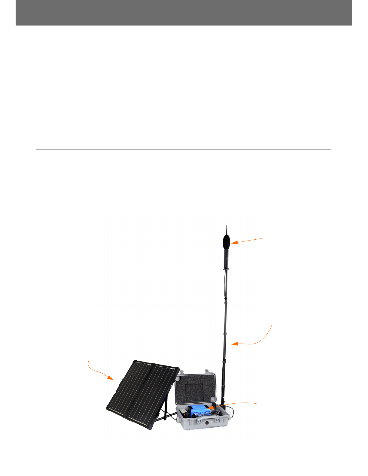
1.1 Overview
The SoundAdvisor Model NMS044 noise monitoring system (NMS044,
system) is the practical solution to long-term or short-term,
unattended sound level monitoring. Power is supplied by a 12 V
battery, and the system is charged by a solar panel, chosen specifically
for the area sunlight availability. It is lightweight, as little as 50 lbs, so
one person can carry to a site and setup within a few minutes.
FIGURE 1-1 NMS044 Overview
Environmentally
protected
microphone and
preamplifier
Telescoping pole keeps
the microphone away
from any sound
reflections in the area.
Do not place near trees
or other large elements.
The outdoor case
protects and securely
fits the battery,
charge controller,
antennas, modem,
and sound level
meter
Place the solar panel
unobstructively
facing the sun’s main
trajectory.
Environmentally
protected
microphone and
preamplifier
Page 7

NMS044 Reference Manual EPS/NMS044 Features 1-2
1.2 EPS/NMS044 Features
Acoustic Measurement
The area sound is measured with a prepolarized microphone and
preamplifier that are environmentally protected in a shroud on a
telescoping pole, which is mounted to the case.
Portable
The NMS044 can be deployed, before, during, or after you setup the
831C to make your measurements.
Low Power Consumption
LEARN MORE To learn more
about power consumption,
see “NMS044 Power Draw” on
page A-2.
A 12 V battery powers the system, which is charged by a solar panel
through a charge controller. The system can run, without recharging,
for about a week. Sunlight needed to reboot the system after a power
loss is minimal and full charge is reached in only a few hours.
Continuous Sound Measurements
If the batteries are ever completely depleted, the system will shut off
safely. When the battery is recharged sufficiently, it will power on and
the measurement will continue. This feature runs without any
prompting from the user.
Connectivity
Connect to a cellular network using the RV50 and access the 831C to
view/download data from a PC at anytime. Control the system from a
web browser from wherever you are.
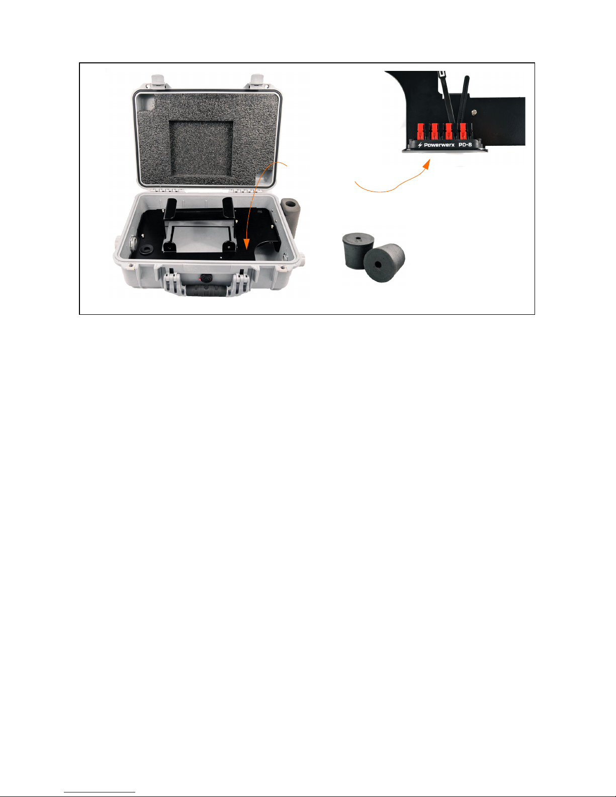
1.3 Components
CCS051
• Environmentally protected case with foam inserts, attachment
bracket, and cable gaskets
• Metal Case Plate
• Power distribution block
• Rubber Stoppers - Depending on which preamplifier is used,
one is used for CBL222-08 or CBL222-20, and one is used for EXC
cables.
• Silicon grease for cable glands
Page 8
NMS044 Reference Manual Components 1-3
FIGURE 1-2 CCS051
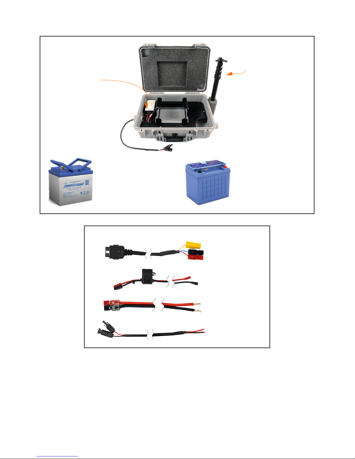
EPS044
• All that is included in the CCS051
• BAT019 45 Ah 12 V LiFePo Battery or BAT020 35 Ah 12 V SLA Battery
• Telescoping pole with guy wire ring
• PSA038 Genasun Solar Charge Controller
• Controls the charge of the solar panel to the battery and
indicates if the battery is charging or fully charged with
the LED light. See A.5.3 "PSA038 Genasun Solar Charge
Controller" on page A-5
• Safe to use with BAT019 and BAT020
• CBL226-02 Charge controller to power block cable
• CBL225-01 Fused battery cable
• CBL228-03 Solar connectors to solar charger cable
• CBL224-02 831C to power block cable
•Canvas bag
Metal plate with
attached power
distribution block
(underneath)
Rubber Stoppers
Page 9
NMS044 Reference Manual Components 1-4
FIGURE 1-3 EPS044 Hardware
FIGURE 1-4 EPS044 Cables
EPS044-SLA
includes the
35 Ah 12 V SLA
Battery
(BAT020)
EPS044-LFP
includes the
45 Ah 12 V
LiFePo Battery
(BAT019)
PSA038 Solar Charge
Controller
Telescoping pole
with guy wire ring
CBL226-02
CBL225-01
CBL224-02
CBL228-03
Page 10

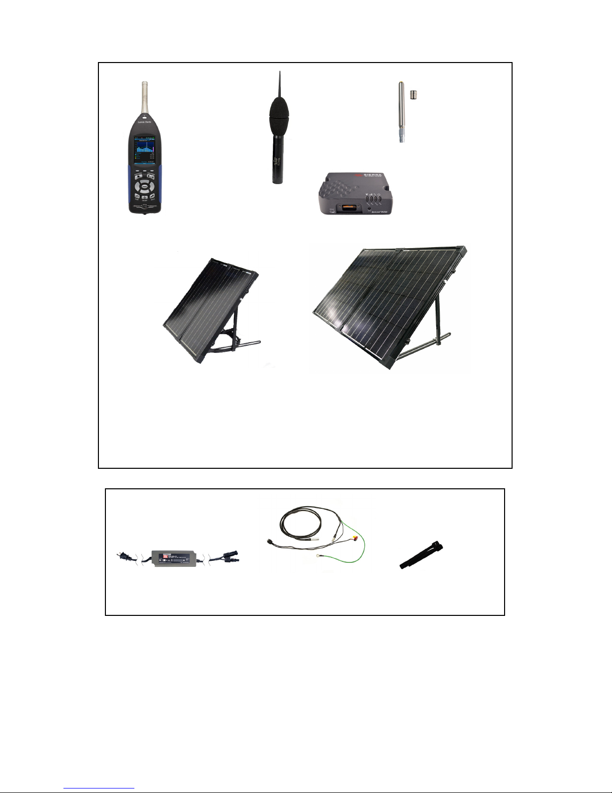
NMS044 Reference Manual Components 1-5
NMS044
• All items listed above for CCS051 and EPS044 (either the
EPS044-SLA or EPS044-LFP, see Figure 1-3 EPS044 Hardware).
• SoundAdvisor Model 831C Sound Level Meter (831C, SLM,
meter)
• Firmware options 831C-LOG, 831C-ELA and 831C-SW
• Default NMS044 measurement setup
• Four NiMH AA batteries
• COM-RV50-DC Cellular Gateway with dual antennas
TAKE NOTE A SIM card for the
RV50 cellular gateway is not
included and will need to be
purchased through a cellular
provider. See “Configure the
RV50 Gateway” on page 2-3.
• SLP001 60 W or SLP002 100 W Solar Panel
• EPS2116 Environmental protection system for microphone and
preamplifier
• PRM2103-FF Preamplifier
• 377B02 Microphone
• PSA039 120 AC Battery Charger Adapter
• CBL222-08 Cable from PRM2103 to 831C
• CBL223-02 RV50 to power block cable
• CBL138 USB to a Mini B used for system setup
• DVX015 2 port USB adapter
• Phillips #2 screwdriver
• Phillips #0 screw driver
Page 11
NMS044 Reference Manual Components 1-6
FIGURE 1-5 NMS044 Hardware
FIGURE 1-6 NMS044 Cables and Accessories
SoundAdvisor
Model 831C
Sound Level
Meter
COM-RV50-DC
Cellular Gateway
NMS044-SLP60
&
NMS044-LFP60
includes the
SLP001 60 W
Solar Panel
EPS2116
Environmental
Protection
Shroud
PRM2103
preamplifier
and 377B02
microphone
NMS044-SLP100
&
NMS044-LFP100
includes the
SLP002 100 W
Solar Panel
CBL222-08 Velcro Ties for the
CBL222-08 and pole
PSA039
Page 12
NMS044 Reference Manual Optional Accessories 1-7
1.4 Optional Accessories
• 831-MEM32G USB Flash Storage
• CAL200 Precision Acoustic Calibrator
• CAL250 Precision Acoustic Calibrator
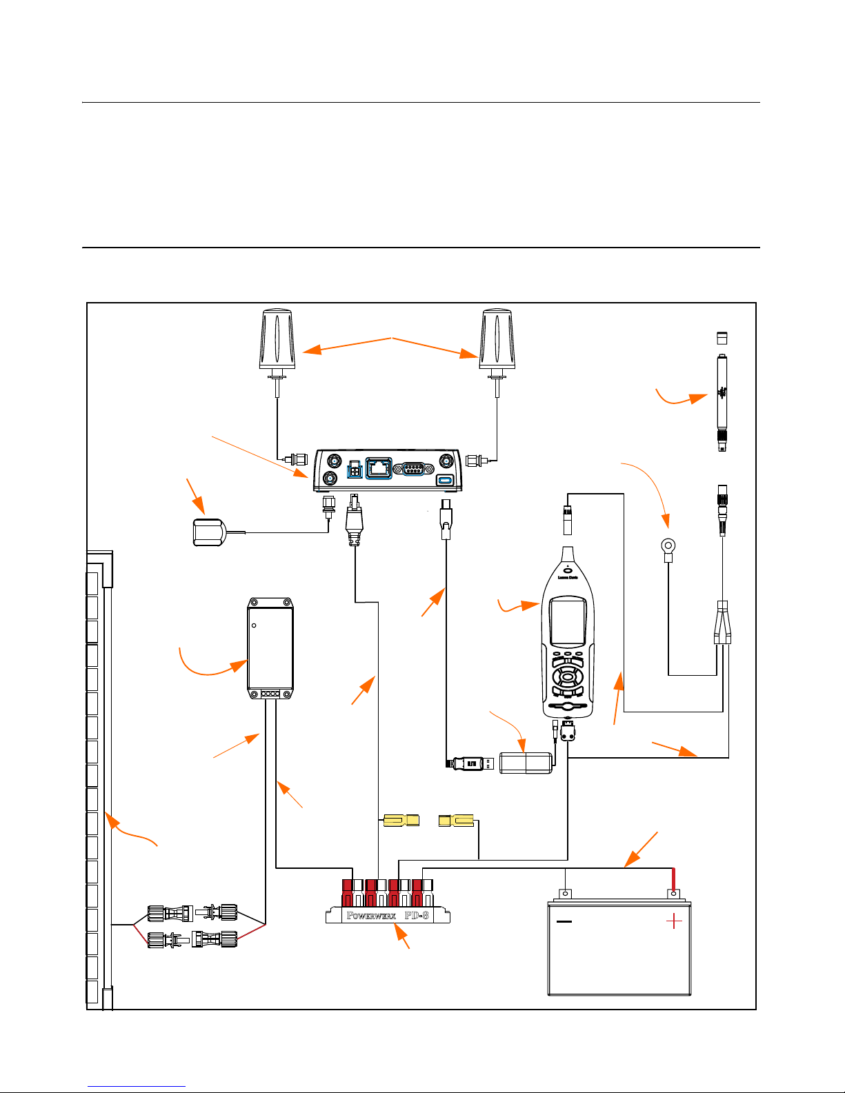
1.5 Wiring Diagrams
FIGURE 1-7 System Wiring Diagram
Cellular Antennas
PRM2103-FF
Preamplifier
and
Microphone
Sound
Level
Meter
PSA038
Solar Charge
Controller
COM-RV50-DC
Cellular Gateway
GPS Antenna
Power Distribution Block
Solar Panel
CBL222
CBL223
Terminal Lug
(ground to
plate in case)
Battery
CBL226-02
CBL225
CBL228-03
DVX015
2-port
USB Hub
CBL218
Page 13
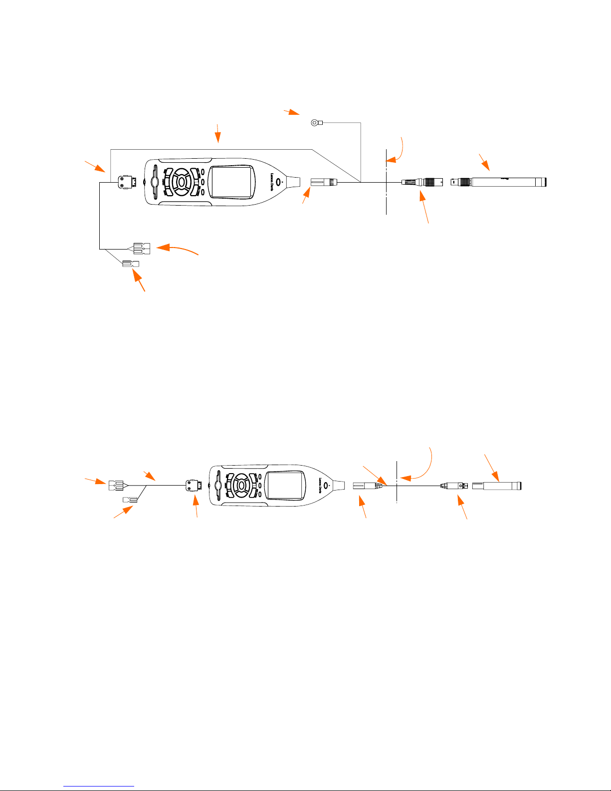
NMS044 Reference Manual Wiring Diagrams 1-8
The following diagram shows the wiring details for the PRM2103
outdoor preamplifier, CBL222 cable, and the 831C.
FIGURE 1-8 Wiring Diagram for PRM2103
The following diagram shows the wiring details for the PRM831
preamplifier, EXCXXX cable, CBL2224and the 831C. This is an optional
wiring setup for the case that a PRM831 preamplifier is used instead of
the PRM2103 outdoor preamplifier.
FIGURE 1-9 Wiring Diagram for PRM831
1/4” Ground Lug
Case wall
10-pin connector
PRM2103
Anderson
connector to
power block
5-pin connector
SoundAdvisor Model 831C
18-pin
connector
to I/O
connector
CBL222
Yellow On/Off Trigger
Case wall
5-pin connector
PRM831
5-pin connector
SoundAdvisor Model 831C
Anderson
connector
to power
block
EXCXX
Yellow on/off trigger
CBL224
18-pin
connector
to I/O
connector
Page 14

NMS044 Reference Manual Overview 2-1
Module 2 Get Started
2.1 Overview .............................................................................................................................. 2-1
2.2 Ready Battery ......................................................................................................................2-1
2.2.1 Install Battery ........................................................................................................ 2-1
2.2.2 Charge Battery ...................................................................................................... 2-2
2.3 Configure the RV50 Gateway ..............................................................................................2-3
2.3.1 Install SIM Card ..................................................................................................... 2-3
2.3.2 Configure for Remote Communication ...............................................................2-4
2.4 Model 831C SLM Settings ....................................................................................................2-8
2.4.1 Shutoff Voltage .....................................................................................................2-8
2.1 Overview
TAKE NOTE This module
assumes that you have the
complete NMS044 and all its
components. For EPS044 the
setup is similar and the
following modules can be
adjusted to your equipment.
When you first receive the NMS044 system you will need to perform
several “first use” procedures to get your system ready for deployment.
While most steps can be done in the field or after deployment, these
steps are recommended to do prior.
2.2 Ready Battery
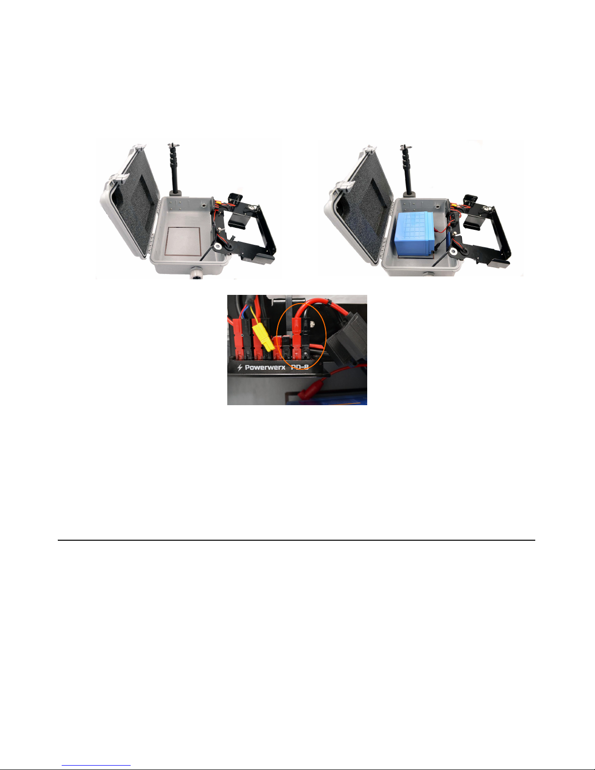
2.2.1 Install Battery
TAKE NOTE Connect all wires
and devices prior to turning
on the system.
Open case and carefully lift out the plate as to not pull any wires loose.
Set on an angle away from case, to expose the back.
Step 1 If not already in place, insert the battery (BAT019 or
BAT020) in the case inside the guide lines, with terminal
toward power block. See Figure 2-1 Battery Installation.
Step 2 Insert the connectors to the power distribution block - red
to red and black to black, side by side in any available
connector.
Page 15
NMS044 Reference Manual Ready Battery 2-2
Step 3 Place the mounting plate back into the case, over the
battery, until set all the way in.
Step 4 If installing a BAT020, insert foam block to fill empty space
by the terminals.
FIGURE 2-1 Battery Installation
TAKE NOTE The 831C power
button 0 controls the power
in the whole system. It is used
to turn off and on the
NMS044. Additionally,
connecting the battery will
also turn the system on.
2.2.2 Charge Battery
It is recommended that you charge the battery prior to deployment. A
PSA039 AC Battery Charger is included for this purpose. Connect the
solar connectors together, and use the plug to connect to an external
power source (wall outlet) until charged. You will know it is fully
charged when the PSA038 Genasun Solar Charge Controller is green
(blinking indicates it is charging, constantly on indicates charge is full),
see A.5.3 "PSA038 Genasun Solar Charge Controller" on page A-5.
If there is no light, ensure the battery is properly installed and the
system is turned on.
CAUTION The yellow
connector does not
connect in the power
block. Do not attempt to
connect the yellow
connector to a red or black
connector.
Page 16
NMS044 Reference Manual Configure the RV50 Gateway 2-3
2.3 Configure the RV50 Gateway
The RV50 gateway requires a SIM card for access and service.
TAKE NOTE The NMS044 does
not regulate data usage.
When purchasing a SIM card, you will need:
• Adequate data plan. Significant charges may occur if the plan is
exceeded.
• Do not need messaging/voice on the plan
• Public IP address
TAKE NOTE Cellular providers
may block incoming
connection requests to a SIM
with a dynamic IP address.
Check with the cellular
provider to assure that
incoming connection
requests are allowed.
• A public IP address is needed in order to connect
remotely with the 831C. If the plan does not have a
public IP address you will not be able to access and
control the system.
• A static IP address or alternative dynamic IP with
Dynamic Domain Name Service (DDNS) as an alternative
can be used, however with this option you can not
remotely access the system. You will still be able to
upload files to SFTP or Dropbox.
•APN
• Request the APN from your cellular provider. You will
need this to configure for remote use.
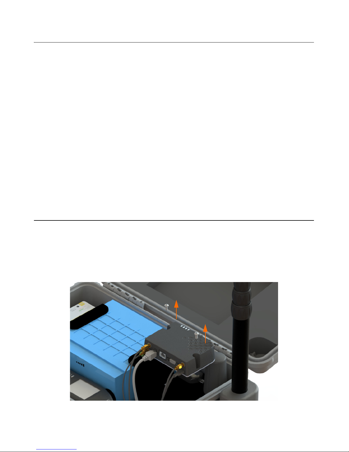
2.3.1 Install SIM Card
With system powered off, install the SIM card by following these steps:
LEARN MORE To learn more
about the RV50 gateway, refer
to the Sierra Wireless website.
Step 1 Using the provided #2 Phillips head screw driver, unscrew
the two screws located on the RV50, disconnecting the
gateway from the case plate.
FIGURE 2-2 Removing RV50 from case plate
Step 2 Using the #0 screwdriver, unscrew the two screws holding
the front SIM card door closed. Insert your card into to
Page 17

NMS044 Reference Manual Configure the RV50 Gateway 2-4
RV50, press in to slot until it clicks. Screw the door closed
again.
FIGURE 2-3 RV50 Sim Card Slot
Step 3 Remount the modem in the case with the two screws.
Hand tight.
2.3.2 Configure for Remote Communication
TAKE NOTE If you’ve purchased
the RV50 Gateway separately
or it has been reset to factory
settings, you will need to
upload the LD settings first
before you can configure for
remote use. For procedures
on loading the LD settings,
see A.7 "Configuring LD
Settings for the RV50" on page
A-7.
You will need to configure your gateway for remote communication
prior to deployment. Once the gateway is installed with a SIM card, and
the charged battery is assembled, you are ready to begin.
To setup for remote communication, follow these steps:
Step 1 The Ethernet port on the gateway has been disabled for
power saving reasons and cannot be used to connect to.
Disconnect the USB cable which is connected to the
gateway, using a separate USB cable, connect the gateway
directly into your computer. The USB cable now connects
the RV50 gateway to your PC.
FIGURE 2-4 Connecting to RV50
USB Cable Connect separate mini B USB
cable into the RV50 and to a PC
Unplug USB cable
Page 18

NMS044 Reference Manual Configure the RV50 Gateway 2-5
Step 2 Turn system ON by pressing the power button 0 on the
831C (if not already on).
Step 3 Open a web browser on the connected PC.
Step 4 Enter http://192.168.14.31:9191 into the address bar.
TAKE NOTE If the login in not
working, this may be a sign
that the gateway does not
have LD settings loaded. See
A.7 "Configuring LD Settings
for the RV50" on page A-7.
Step 5 Log in as “user” with configured password
“LD_NMSystem16”.
FIGURE 2-5 User Login
Step 6 Navigate WAN/Cellular SIM Slot 1 Configuration and
open the + by the Network Credentials.
FIGURE 2-6 WAN/Cellular
Page 19

NMS044 Reference Manual Configure the RV50 Gateway 2-6
Step 7 Enter the APN provided by your cellular provider in the
User Entered APN.
Step 8 Click Apply and Reboot.
Step 9 Login again. Navigate to Status Home Network State.
This should say Network Ready if everything was correct.
Verify the Active WAN IP Address matches the static
address given to you by your cellular provider.
FIGURE 2-7 Status
Step 10 Disconnect the USB from the PC and RV50. Return the mini
USB to the RV50.
FIGURE 2-8 Disconnecting USB/Reconnecting USB
Step 11 Perform a reboot on the 831C.
ON/OFF 0 Reboot.
By connecting via IP address to the 831C prior to deployment, you can
determine if the service is working properly. To connect to the 831C
with a mobile device, follow these steps:
Step 1 Open a web browser (Chrome is recommended) on your
mobile device.
Disconnect the USB from the PC
and RV50
Return the mini USB to the RV50.
Page 20

NMS044 Reference Manual Configure the RV50 Gateway 2-7
Step 2 In the URL, type the IP address provided to you from your
cellular provider, then /SoundAdvisor. Press enter.
• Ex: 126.120.130.65/SoundAdvisor
Step 3 The browser will show the current state of the meter, the
same screen as the meter. You can operate the 831C from
this view.
FIGURE 2-9 Mobile View
Page 21

NMS044 Reference Manual Model 831C SLM Settings 2-8
2.4 Model 831C SLM Settings
While the user indicated properties are unique to each user and the
intended use, the following settings are recommended for use in the
NMS044 system:
• Auto-Off: Never
• Backlights On: 5 s - 10 s (power saving)
• Keypad Backlight: Off (power saving)
• Auto-Store: Store
FIGURE 2-10 System Properties
2.4.1 Shutoff Voltage
Set the shutoff voltage on the 831C to reflect the battery type that is
installed in the NMS044 system. To indicate this setting, navigate Tools
System Properties Power. Enter the correct voltage and click Close
and Yes to save changes.
To determine the shutoff voltage, use the table below:
Table 2.1 Shutoff Voltage
Battery Shutoff Voltage
The LiFePo Battery (12V 45Ahr) 12.0 V
The SLA Battery (12V 35Ahr) 10.8 V
Page 22

NMS044 Reference Manual Overview 3-1
Module 3 Deployment
3.1 Overview .............................................................................................................................. 3-1
3.2 Travel Packs ......................................................................................................................... 3-2
3.3 Assemble EPS2116 and Preamplifier ................................................................................. 3-2
3.4 Install Pole and EPS2116 to System ................................................................................... 3-4
3.5 Connect Solar Panel ............................................................................................................3-6
3.6 Turn System ON ................................................................................................................... 3-7
3.7 Calibrate ..............................................................................................................................3-8
3.8 Due Diligence ....................................................................................................................... 3-9
3.8.1 Verify Battery is Charged/Charging ....................................................................3-10
3.8.2 Check Cellular Service ........................................................................................3-10
3.8.3 Secure case with lock ......................................................................................... 3-10
3.1 Overview
The following module will demonstrate the setup of the NMS044 in the
field.
FIGURE 3-1 Deployment Overview
A fully deployed
NMS044 with cable
tie downs
Page 23

NMS044 Reference Manual Travel Packs 3-2
3.2 Travel Packs
Assemble all components in the recommended three travel packs. See
Figure 3-2 NMS044 Deployment Travel Packs
FIGURE 3-2 NMS044 Deployment Travel Packs
3.3 Assemble EPS2116 and Preamplifier
LEARN MORE To learn more
about the assembly of the
EPS2116 refer to the EPS2116
Reference Manual
(IEPS2116.01)
Step 1 Remove rubber cap from top of preamplifier. Place
microphone on preamplifier, then gently screw together
until hand tight. Set aside (you can store these connected
so you do not need to repeat this step with every
deployment).
FIGURE 3-3 Connecting Microphone and Preamplifier
Solar Panel
in case
EPS2116, telescoping
pole, preamplifier, and
microphone, guy wire
ring, and stakes
NMS044 case with battery,
Model 831C SLM, RV50
gateway, charge controller
antennas, and all
connections
Page 24

NMS044 Reference Manual Assemble EPS2116 and Preamplifier 3-3
Step 2 Hold EPS2116 windscreen and birdspike together and
unscrew from top. Screw together top and base. The
EPS2116 should now appear in two components, see
Figure 3-4 EPS2116 Separated.
FIGURE 3-4 EPS2116 Separated
Step 3 Thread the CBL222-08 cable up through the base and top.
Align red dots on bottom of preamplifier to top of CBL22208, gently push together until mounted. Gently ease the
cable back down until the microphone is seated at the top
of the EPS2116. As illustrated in Figure 3-5.
FIGURE 3-5 EPS2116 Threading
Top
Base
Birdspike
Windscreen
123
Page 25

NMS044 Reference Manual Install Pole and EPS2116 to System 3-4
Step 4 Holding windscreen and birdspike over the top, screw the
assemblies together (this can wait until after calibration,
see “Calibrate” on page 3-8.
TAKE NOTE Step 4 can be done
after calibration, see
“Calibrate” on page 3-8.
CAUTION If you need to
remove the windscreen, do
not pull it off the birdspike
with an upward motion. First,
unscrew the birdspike by
twisting its top and then pull
the windscreen down over the
bottom of the unscrewed
birdspike.
3.4 Install Pole and EPS2116 to System
Step 1 Remove the protective cap from the top and the bottom of
the telescoping pole. Place guy wire ring on the top of the
pole. Place the EPS2116 on top and hold it still, twist the
pole only, making sure to have the signal cable between
two of the tie downs of the ring to not over strain the
cable.
FIGURE 3-6 EPS2116 to Telescoping Pole
Page 26

NMS044 Reference Manual Install Pole and EPS2116 to System 3-5
Step 2 Wrap the cable around the pole (2) two times in a counter
clockwise orientation. Place into the bracket and twist
clockwise to tighten.
FIGURE 3-7 Telescoping Pole with EPS2116 to system
Step 3 Extend the sections of the pole by loosening the
telescoping pole clamp and then tighten.
Step 4 Use hook and loop cable straps (already on the cable) to
fix the signal cable to the pole.
Step 5 Use the guy wires and stakes to steady the pole by
attaching them to the guy wire ring and then to the
ground.
Page 27

NMS044 Reference Manual Connect Solar Panel 3-6
3.5 Connect Solar Panel
Step 1 Unlatch solar panel to open.
Step 2 Loosen thumb screws to extend legs. Match angle on
either side.
Step 3 Connect the solar connectors together.
Step 4 Place solar panel in a secure, unobstructed flat spot facing
toward the sky with optimal sunlight.
FIGURE 3-8 Solar Connection
Procedures for Disconnecting Solar Connectors
To disconnect the solar connectors, a solar connector tool is provided.
Insert the tool in the middle of the connection, to pinch the locking
mechanism, then pull apart.
FIGURE 3-9 Solar Connector Removal
Stakes or a heavy weight,
like sandbags, are
recommended for
keeping the solar panel
grounded during
deployment.
1
2
Page 28

NMS044 Reference Manual Turn System ON 3-7
3.6 Turn System ON
Press the power button 0 on the 831C to turn the whole system on.
The Model 831C SLM power button 0 controls the power in the whole
system. It is used to turn off and on the NMS044.
FIGURE 3-10 NMS044 Case Components
Page 29

NMS044 Reference Manual Calibrate 3-8
3.7 Calibrate
TAKE NOTE For best results,
use Larson Davis Precision
Acoustic Calibrators and
Larson Davis MicrophonePreamplifiers.
Refer to your calibrator and microphone-preamplifier product manuals
for specific requirements in performing the acoustic calibration.
TAKE NOTE It is recommended
to perform a calibration after
the system is deployed.
Step 1 Holding windscreen and birdspike together, unscrew the
assemblies until they come apart.
Step 2 Place the calibrator over the microphone. Apply it
carefully to avoid sudden large pressure changes to the
diaphragm.
Step 3 Navigate Tools Calibrate on the meter.
Step 4 Select the calibrator and click the Edit Settings button if
the calibrator settings need to be modified. Ensure that
the settings correspond to those described in the manual
for the selected calibrator.
Step 5 Turn calibrator on.
Step 6 Click the Do Calibration button on the meter.
FIGURE 3-11 Acoustic Calibration
Page 30

NMS044 Reference Manual Due Diligence 3-9
Step 7 After a few seconds, a message appears indicating the
measured difference and a prompt to save the results.
Click Yes to save the calibration or No to reject it.
Step 8 Carefully remove the calibrator from the microphone.
FIGURE 3-12 Calibration Results
Click the Calibration History tab to view either acoustic calibration or
calibration check summaries.
Step 9 When calibration process is complete, assemble
windscreen and birdspike back on to the microphone.
3.8 Due Diligence
Follow these steps prior to leaving the system:
FIGURE 3-13 Due Diligence
Check the charge
controller and the RV50
for operation status
Page 31

NMS044 Reference Manual Due Diligence 3-10
3.8.1 Verify Battery is Charged/Charging
You will know the is battery fully charged when the PSA038 Solar
Charge Controller is green. A blinking LED indicates it is charging,
constantly on indicates charge is full. See A.5.3 "PSA038 Genasun Solar
Charge Controller" on page A-5.
3.8.2 Check Cellular Service
By connecting to the 831C while in the field, you can determine if the
service is working properly. To connect to the 831C via a mobile device
(with active cellular service), follow these steps:
TRY THIS Check the service
lights, see A.5.2 "COM-RV50DC-U/E Cellular Gateway" on
page A-3.
Step 1 Open a web browser (Chrome is recommended)
Step 2 In the URL, type the IP address provided to you from your
cellular provider, then /SoundAdvisor. Press enter.
• Ex: 126.120.130.65/SoundAdvisor
Step 3 If you have cellular service, then the browser should show
the current state of the meter, the same screen as the
meter. You can operate the 831C from this view.
3.8.3 Secure case with lock
This step is optional but recommended. The NMS044 case latches tight,
and a lock can be used to secure it. You can chain the system to a fixed
object as well, to deter theft.
Page 32

NMS044 Reference Manual Overview 4-1
Module
4 Making Measurements
4.1 Overview .............................................................................................................................. 4-1
4.2 Connect to G4 LD Utility ......................................................................................................4-1
4.3 Default NMS044 Setup File ..................................................................................................4-2
4.4 Email/Text Alerts .................................................................................................................4-5
4.4.1 Listening to .OGG Files ..........................................................................................4-6
4.1 Overview
Setting up the Model 831C Sound Level Meter can be done prior, during,
or after deployment. You have complete accessibility to make settings
changes, check the measurement, or download the file at any step of
the process.
4.2 Connect to G4 LD Utility
TAKE NOTE G4 LD Utility can
also be connected to multiple
instruments through all
connection types.
You can connect directly to a PC from the meter with a mini USB cable;
however, this section will describe connecting via TCP/IP.
Launch the software and click Connect.
FIGURE 4-1 Connect
In the Connect to Meter dialog box, select 831 as the device and TCP/IP
as the connection type. Enter the IP address given by your cellular
provider for the RV50 modem SIM card and the port number for the
instrument (most likely port 80). Click Connect.
Page 33

NMS044 Reference Manual Default NMS044 Setup File 4-2
FIGURE 4-2 Connect to Meter
4.3 Default NMS044 Setup File
For convenience, there is a default setup file for the NMS044 on the
meter that can be set to Active. If you make any changes to this setup,
you can save it as a custom setup file for multiple use, even transferring
it to a PC to be transfered to any number of meters. To do this, follow
these steps:
Step 1 Using G4, mobile device, or the meter itself navigate to the
Setup Manager for the meter. (Tools Setup Manager)
Step 2 Select the setup “NMS044”, press Enter.
Step 3 Select Set to Active.
FIGURE 4-3 Set to Active
Select 831 as
device
Select the connection
type as TCP/IP
Select Add Meter
then enter unique
name, IP address,
and port number
Select Connect
when finished
Page 34

NMS044 Reference Manual Default NMS044 Setup File 4-3
The NMS044 setup file contains metrics that are commonly measured
when measuring outdoor noise. These default settings will log one
hour intervals, daily results, and one second time histories to view
noise levels as a function of time. Triggers SPL 2 (set to 65 dB) and/or
PEAK 3 (set to 140 dB) will send email alerts any time there is an event
detected. This default setup is described below.
FIGURE 4-4 NMS044 Settings: Control
TAKE NOTE Measurement
history is only available with
the 831C-ELA or 831C-MRS
option purchased and
installed on the Model 831C
SLM. For more information,
see “Contact Larson Davis” on
page i-2.
It is recommended to set Continuous as the Run Mode for the NMS044.
This mode will begin a run every time the meter is powered on and will
continue to run until a manual Stop or the meter is powered off. If the
system loses power and then is recharged sufficiently, the system will
power on and a measurement will start on its own. The Daily Auto Store
is set to store once a day, so you will have 24 hour measurement files.
The PRM2103 preamplifier can do a daily automatic calibration check
to ensure that the measurements are accurate. A recommended time
for the calibration check is 2:30:00.
FIGURE 4-5 NMS044 Settings: Time History
Page 35

NMS044 Reference Manual Default NMS044 Setup File 4-4
TAKE NOTE
Time History is only
available with the 831C-LOG
or 831C-MRS option
purchased and installed on
the Model 831C SLM. For more
information, see “Contact
Larson Davis” on page i-2.
Time History at one second period will create one second records in
each measurement. For each record, the selected metrics will be
logged. The NMS044 setup enables the default metrics.
FIGURE 4-6 NMS044 Settings: Triggers, Events, and Sound
TAKE NOTE Options 831C-SR,
831C-MSR, 831C-ELA enable
this feature and must be
purchased and installed on
the Model 831C SLM. For more
information, see “Contact
Larson Davis” on page i-2.
Make event-based sound recordings that can be sent via email or SMS
and stored in the measurement data with these settings. When the area
sound exceeds the SPL 2 or Peak 3 triggers, a sound recording will
begin and record 7 seconds of sound, which will immediately be sent as
an email or text message. To assign the recipients, see “Email/Text
Alerts” on page 4-5.
Page 36

NMS044 Reference Manual Email/Text Alerts 4-5
4.4 Email/Text Alerts
TAKE NOTE Email alerts are
enabled on an Event History
setup. Once enabled, the
email preferences from
System Properties will be
used for the alerts.
Send text/email alerts from the Model 831C SLM for noise exceedances
and other features (ex. cloud storage notifications). Sound can be
recorded and sent via email in the alert as well.
To set up email alerts, follow these steps:
Step 1 Connect the 831C to a router with Internet access via WiFi
or Ethernet.
Step 2 On the meter, or using G4, navigate System Properties
Email.
FIGURE 4-7 System Properties: Email
TAKE NOTE The email server
the 831C connects to needs to
be SMTP server with TLS
authentication (using port
587). When setting up an
email account through a
public server (i.e. Gmail or
Yahoo), you may need to
enable SMTP access for the
account, typically through
secure login settings. To avoid
spam filters, add the host
email addresses to your
contact list.
Step 3 Enter an email hostname, username, and password.
Step 4 Enter the email addresses the recipients will reply-to.
Step 5 Indicate the email address for the text alert. For this field,
the phone number @ carrier email address will be
accepted. For example, 80155555555@vtext.com will send
a text message to a Verizon Wireless mobile device.
Step 6 Send a test email.
Step 7 Close and save.
Example: Run a measurement. When the SPL 2 or Peak 3 Triggers
exceed their indicated thresholds, an email will be sent with a sound
recording attached to the recipients you have indicated.
Page 37

NMS044 Reference Manual Email/Text Alerts 4-6
FIGURE 4-8 Example Email
4.4.1 Listening to .OGG Files
The 831C supports interfacing with the meter using a browser. This
function is in beta testing, and the functionality is not complete.
Support for browsers and audio playback is summarized below:
Table 4.1 Audio Playback
Platform Browser Audio File (.OGG)
Windows Internet Explorer - Not
recommended
No Supported
Chrome - Recommended Supported
Firefox Not Tested
Microsoft Edge Not Tested
Mobile (Apple &
Android)
Chrome - Recommended Supported
Safari Requires CODEC download
and installation
Opera Not Tested
Symbian Not Tested
Page 38

NMS044 Reference Manual Physical Characteristics A-1
Appendix
A Additional Features
A.1 Physical Characteristics ......................................................................................................A-1
A.2 NMS044 Power Draw ...........................................................................................................A-2
A.2.1 Sunlight Hours ......................................................................................................A-2
A.2.2 Alternative Solar Panel .........................................................................................A-2
A.3 Long Term Storage ..............................................................................................................A-2
A.4 Shipping Information ..........................................................................................................A-2
A.4.1 Lithium Iron Phosphate Battery (LiFePo) ............................................................A-3
A.5 LED Indicators ......................................................................................................................A-3
A.5.1 SoundAdvisor Model 831C Sound Level Meter ....................................................A-3
A.5.2 COM-RV50-DC-U/E Cellular Gateway ...................................................................A-3
A.5.3 PSA038 Genasun Solar Charge Controller ...........................................................A-5
A.6 Removing Cables from Case ...............................................................................................A-6
A.7 Configuring LD Settings for the RV50 .................................................................................A-7
A.8 Declaration of Conformity ................................................................................................A-15
A.1 Physical Characteristics
Weight
• NMS044 with SLP001 & BAT019, cases: 23 kg (50 lbs)
NMS044 without battery or solar panel: 8.18 kg (18 lbs)
• SLP001 60 Watt solar panel: 9 kg (19.85 lbs)
• SLP002 100 Watt solar panel: 12.27 kg (27.05 lbs)
• Telescoping pole, EPS21116, and PRM026 in bag: 1.92 kg (4.2
lbs)
• BAT019: 5.8 kg (12.8 lbs)
• BAT020: 11.2 kg (24.7 lbs)
Dimensions
• NMS044 Case: 61 cm x 35.5 cm x 18 cm (24” x 14” x 7”)
• SLP001: 66 cm x 35.5 cm x 8 cm (26” x 14” x 3”)
• SLP002: 50 cm x 68.5 cm x 8 cm (20” x 27” x3”)
• Canvas Bag: 48 cm x 23 cm x 15 cm (19” x 9” x 6”)
Deployment Dimension
3 m (10’) diameter on the ground with a 2 m (6.5’) overhead clearance
minimum. Though sound reflections are possible with objects that
could be nearby, so more clearance is recommended.
Page 39

NMS044 Reference Manual NMS044 Power Draw A-2
A.2 NMS044 Power Draw
The NMS044 system draws power from the connected battery. It cannot
be powered any other way (ex. wall outlet).
The following table was generated from the recommended setup for
the RV50, see “Configure the RV50 Gateway” on page 2-3. Other
options are available that will change the power consumption of the
system and any deviation from the recommended setup. Setting up
scheduled run-time(s) on the 831C meter will cause the meter to turn
off when not running which will extend the number of days of backup.
All of these values are given with the assumption that no external
power is attached (solar, outlet, etc.).
A.2.1 Sunlight Hours
You are encouraged to take advantage of the most daylight, direct sun
for your area. To better understand your sunlight, refer to
http://rredc.nrel.gov/solar/old_data/nsrdb/1961-1990/redbook/atlas/
http://re.jrc.ec.europa.eu/pvgis/countries/countries-europe.htm
A.2.2 Alternative Solar Panel
The NMS044 system can support solar panels that are <140 W.
A.3 Long Term Storage
If your system is to be stored for more than one week, unplug and/or
remove the battery from the case and store separately.
A.4 Shipping Information
CAUTION Do not transport with
lid open.
Prior to shipping the system, always disconnect the battery from the
power block terminal, as to not drain the battery while in transit. The
battery can be shipped in the case, with the correct shipping labels on
the outside of the box.
Table A.1 Draw and days of battery backup
System continuously running
3.1 W
The LiFePo Battery (12V 45 Ahr) >7.5 days
The SLA Battery (12V 35 Ahr) >6 days
System continuously running and streaming
3.6 W
The LiFePo Battery (12V 45 Ahr) >6 days
The SLA Battery (12V 35 Ahr) >4.5 days
Page 40

NMS044 Reference Manual LED Indicators A-3
A.4.1 Lithium Iron Phosphate Battery (LiFePo)
The BAT019 LiFePo is considered Class 9 Hazardous Material, and
additional requirements will need to be met when shipping. A company
and/or individual will need to be 49 CFR and IATA certified to be able to
ship the BAT019 (which is a lithium battery over 100 W Hr). Additionally,
recertification is required every two years.
Licensing can be obtained through a training course, such as the Lion
Technology online training course - code #HMT 254 “Shipping Lithium
Batteries”.
A.5 LED Indicators
A.5.1 SoundAdvisor Model 831C Sound Level Meter
Charge Status LED
The charge status indicated by an LED on 0 are as follows:
• LED 0 continuously lit: Charging
• LED 0 not lit: Not charging
• LED 0 winking: Charging stopped (battery fault)
• LED 0 fast blinking: meter is powering up or shutting down
A.5.2 COM-RV50-DC-U/E Cellular Gateway
When installed and running, the state of the RV50 is indicated in the
four LED indicators on the side and bottom of the device. Refer to the
following table for the LED behavior:
Table A.2 Measurement Status LED Indicators
Measurement State
Red LED
7 Green LED 9
Stopped with Reset Winking ***- Off
Stopped Blinking **-*-* Off
Paused Flashing *-*- Flashing -*-*
Running Off Blinking **-*-*
Waiting for valid data to
begin running
Delayed wink ----* Off
Page 41

NMS044 Reference Manual LED Indicators A-4
FIGURE A-1 Gateway LED Indications
Table A.3 RV50 LED Indicators
LED Color/Pattern Description LED Power Saving Mode
Power Off No power or input voltage > 36 Vdc or < 7 Vdc
Solid Green Power is present
Green with Amber Flash Power is present and the gateway has a GPS fix
Solid Red Standby mode
Flashing Green When you press the reset button, flashing green indicates when to release
the reset button to reboot the gateway.
Flashing Red When you press the reset button, flashing red indicates when to release the
reset button to reset the gateway to the factory default settings.
Signal Solid Green Good signal (equivalent to 4-5 bars) Off
Solid Amber Fair signal (equivalent to 2-3 bars) Off
Flashing Amber Poor signal (equivalent to 1 bar)
If possible, move the gateway to a location with a better signal.
Flashing Red Inadequate (equivalent to 0 bars)
If possible, move the gateway to a location with a better signal
Network Solid Green Connected to an LTE network Off
Solid Amber Connected to a 3G or 2G network Off
Flashing Green Connecting to a network
Flashing Red No network available
Flashing Red/Amber Network Operator Switching is enabled, but the gateway is unable to locate
the required firmware. For more information, contact Sierra Wireless®.
Activity Flashing Green Traffic is being transmitted or received over the WAN interface.
Flashing Red Traffic is being transmitted or received over the serial port. This behavior
only appears if the RV50 is configured to display it. For more information,
contact Sierra Wireless®.
Flashing Amber Traffic is being transmitted or received over both the WAN interface and the
serial port. This behavior only appears if the RV50 is configured to display it.
For more information, contact Sierra Wireless®.
ALL Green LED chase Radio module reconfiguration/firmware update or Network Operator
Switching is
in progress.
Amber LED chase ALEOS software update is in progress.
Page 42

NMS044 Reference Manual LED Indicators A-5
A.5.3 PSA038 Genasun Solar Charge Controller
The solar charger has one bicolor status LED. When you first connect
your charger to the battery, the LED should blink red then green. The
LED blinks green to indicate that your charger is powered and charging,
and the LED may blink red to indicate errors. Refer to the following list
for more specific indications:
Green LED
• Short blinks every 4-5 seconds
Battery connected, no panel voltage
• Short blinks every 1 second
Panel detected, but not providing power
• Fast short blinks
Charging with low current
• Slower long blinks
Charging with high current
• Long Blink, Short Blink
Charging at internal current limit
• Constant on
Battery is Fully Charged
Red LED
• Two Blinks
Temperature Too High
• Three Blinks
Power Too High
• Four Blinks
Battery Too Low
• Five Blinks
Battery Too High
• Six Blinks
Panel Too High
• Two Long Blinks followed by short blinks
Contact Technical Support
FIGURE A-2 Genasun Solar Charge Controller LED
Page 43

NMS044 Reference Manual Removing Cables from Case A-6
A.6 Removing Cables from Case
In the event that the cables need to be removed from the case, follow
these steps:
Step 1 Remove the CBL228-03 from the charge controller by
unscrewing the terminals and gently pulling the cable out.
Remove the CBL222-08 from the top of the 831C by
pressing the release button and pulling out.
Step 2 Unscrew the gasket by turning counterclockwise.
Step 3 Using your hands on either side of the case wall, gently
push the rubber stopper out. The cable can be removed
through the slit in the stopper.
Step 4 Follow the steps in reverse order to reinstall the cables in
the case.
FIGURE A-3 Removing Cables from Case
12
34
Page 44

NMS044 Reference Manual Configuring LD Settings for the RV50 A-7
A.7 Configuring LD Settings for the RV50
The RV50 Gateway can only be a functioning communication device if it
is configured with the correct settings. If you have purchased a new
RV50 from another source besides Larson Davis or if it has been reset to
factory defaults, you will need to perform these steps to configure your
system to the settings that were installed when first shipped from
Larson Davis.
Upload LD Settings Data File to RV50
Step 1 Attach the mini USB cable from the PC to the gateway. See
Figure 2-4 Connecting to RV50.
Step 2 Open a web browser.
Step 3 Enter http://192.168.14.31:9191 into the address bar.
Step 4 Login as “user” with default password “12345”
FIGURE A-4 Sierra Wireless Login
Step 5 Take note of the version of firmware currently on the
device.
FIGURE A-5 Firmware version
Page 45

NMS044 Reference Manual Configuring LD Settings for the RV50 A-8
Step 6 Check for the latest firmware version at
http://source.sierrawireless.com/ select the proper device
and follow the link Firmware Package.
Step 7 If needed, download and update the firmware according
to the manufacturer's instructions and log back in when it
has rebooted.
Step 8 Navigate to Admin tab.
Step 9 Enter the default “12345” password in Old Password.
Step 10 Enter unique password in both New Password and Retype
Password.
TAKE NOTE Record this
password. If you forget it you
will need to reset the RV50 to
factory settings and
reconfigure.
Step 11 Select Change Password. Select Apply.
FIGURE A-6 Admin Tab
Page 46

NMS044 Reference Manual Configuring LD Settings for the RV50 A-9
Step 12 Select Template on the top right.
Step 13 Select the template file found on the USB device included
with the NMS044 system called “RV50TemplateFile.xml”.
The file can also be found at http://www.LarsonDavis.com
Step 14 Select Apply.
If you are using the template file skip the remaining steps
on the series and you have completed the setup process.
FIGURE A-7 Template File Loading Process
Page 47

NMS044 Reference Manual Configuring LD Settings for the RV50 A-10
LD Settings without Template File
Step 1 If you did not use the template file, navigate to Security
tab.
Step 2 Click on the Port Forwarding section on the left.
Step 3 Change the screen to match what is shown in Figure A-8
Port Forwarding. Port 80 allows for G4 LD Utility to have
access to the HLD on the 831C.
FIGURE A-8 Port Forwarding
Step 4 Apply when finished.
Step 5 Navigate to Services tab.
Step 6 Select ACEmanager section in the left pane.
Step 7 Ensure the settings are as show in
FIGURE A-9 Services - ACEmanager
Step 8 Apply when finished.
Page 48

NMS044 Reference Manual Configuring LD Settings for the RV50 A-11
Step 9 Navigate to Power Management section in the left pane.
Step 10 Select Power Saving Mode.
Step 11 Change the Processor Power Saving Mode to Enable.
FIGURE A-10 Services - Power Management
Step 12 Apply when finished.
Page 49

NMS044 Reference Manual Configuring LD Settings for the RV50 A-12
Step 13 Click on the Telnet/SSH section in the left pane.
Step 14 Set Telnet/SSH Echo on the left pane and set the value to
disable.
Step 15 Apply
FIGURE A-11 Telnet /SS H
Step 16 Navigate to the Location tab.
Step 17 Select Global Settings on the left pane.
Step 18 In the Location Service box choose Enable.
Step 19 Set the TCP GPS Port to 9494.
FIGURE A-12 Location Settings
Step 20 Apply when finished.
Page 50

NMS044 Reference Manual Configuring LD Settings for the RV50 A-13
Step 21 Navigate to the Serial tab.
Step 22 Change the Serial Port to Disable.
FIGURE A-13 Serial
Step 23 Apply when finished.
Step 24 Navigate to the LAN tab.
Step 25 Select the USB section in the left pane.
Step 26 Verify that the settings are as shown in
FIGURE A-14 USB Port
Step 27 Apply when finished.
Page 51

NMS044 Reference Manual Configuring LD Settings for the RV50 A-14
TAKE NOTE
After this change
you will not be able to
connect to the gateway with a
wired Ethernet connection.In
order to restore that
connection without
connecting to the gateway
through the cellular
connection a hard reset must
be performed. This will reset
all items to a factory default
and you would have to start
over on the configuration.
Step 28 Navigate to the Ethernet section in the left pane.
Step 29 Change the Ethernet Port 1 to Disable.
Step 30 Apply when finished.
FIGURE A-15 LAN Settings
Step 31 Select Reboot on the top right.
Step 32 Allow the gateway to save the applied settings and reboot.
Page 52

NMS044 Reference Manual Declaration of Conformity A-15
A.8 Declaration of Conformity
 Loading...