

Page 1

SoundAdvisor
Model 831C Sound Level Meter
Vertrieb für Österreich :
nbn Elektronik Handelsgesellschaft m. b. H.
Riesstraße 146, 8010 Graz | Tel. +43 316 40 28 05 | Fax +43 316 40 25 06www.nbn.at
Page 2

Larson Davis
SoundAdvisor
Model 831C
Reference Manual
Page 3

Copyright
Copyright 2017, by PCB Piezotronics, Inc. This manual is copyrighted, with all rights reserved. The manual may not be copied in
whole or in part for any use without prior written consent of PCB Piezotronics, Inc.
Disclaimer
The following paragraph does not apply in any state or country where such statements are not agreeable with local law:
Even though PCB Piezotronics, Inc. has reviewed its documentation, PCB Piezotronics Inc. makes no warranty or representation,
either expressed or implied, with respect to this instrument and documentation, its quality, performance, merchantability, or fitness
for a particular purpose. This documentation is subject to change without notice, and should not be construed as a commitment or
representation by PCB Piezotronics, Inc.
This publication may contain inaccuracies or typographical errors. PCB Piezotronics, Inc. will periodically update the material for
inclusion in new editions. Changes and improvements to the information described in this manual may be made at any time.
Safety
If the equipment is used in a manner not specified by Larson Davis, the protection provided by the equipment may be impaired.
Record of Serial Number and Purchase Date
SoundAdvisor Model 831C Serial Number: ___________
Preamplifier Model: _________ Serial Number: ___________
Microphone Model: _________ Serial Number: ___________
Recycling
PCB Piezotronics, Inc. is an environmentally friendly organization and encourages our customers to be
environmentally conscious. When this product reaches its end of life, please recycle the product through a
local recycling center or return the product to:
PCB Piezotronics, Inc.
Attn: Recycling Coordinator
1681 West 820 North
Provo, Utah, USA 84601-1341
where it will be accepted for disposal
Warranty
For warranty information, refer to our Terms and Conditions of Sale on our website, www.larsondavis.com/TermsConditions.aspx.
i.1 Contact Larson Davis
Website
www.larsondavis.com
Worldwide Corporate Headquarters
Larson Davis - a PCB Piezotronics division
3425 Walden Avenue
Depew, NY 14043-2495 USA
Toll-free (in the US): 888-258-3222
Phone: 716-926-8243
USA fax: 716-926-8215
E-mail: sales@larsondavis.com
SoundAdvisor Model 831C i-2
Page 4
i.2 Download G4 LD Utility
G4 LD Utility (G4) software enhances the features, flexibility, and ease-of-use of Larson Davis instruments
by providing setup utilities, instrument calibration, computer-based control of the instrument, data download
and manipulation, printing, and export of data to third-party software for post processing and analysis.
When you insert the G4 LD Utility software CD, it will start automatically. If it does not, access the CD drive
and click LDsetup.exe. Alternatively you can download G4 at
http://www.larsondavis.com/G4
The install program prompts for any additional required information. A PCB Piezotronics menu item will be
created under the Program menu item in the Start menu and a shortcut will be placed on the desktop.
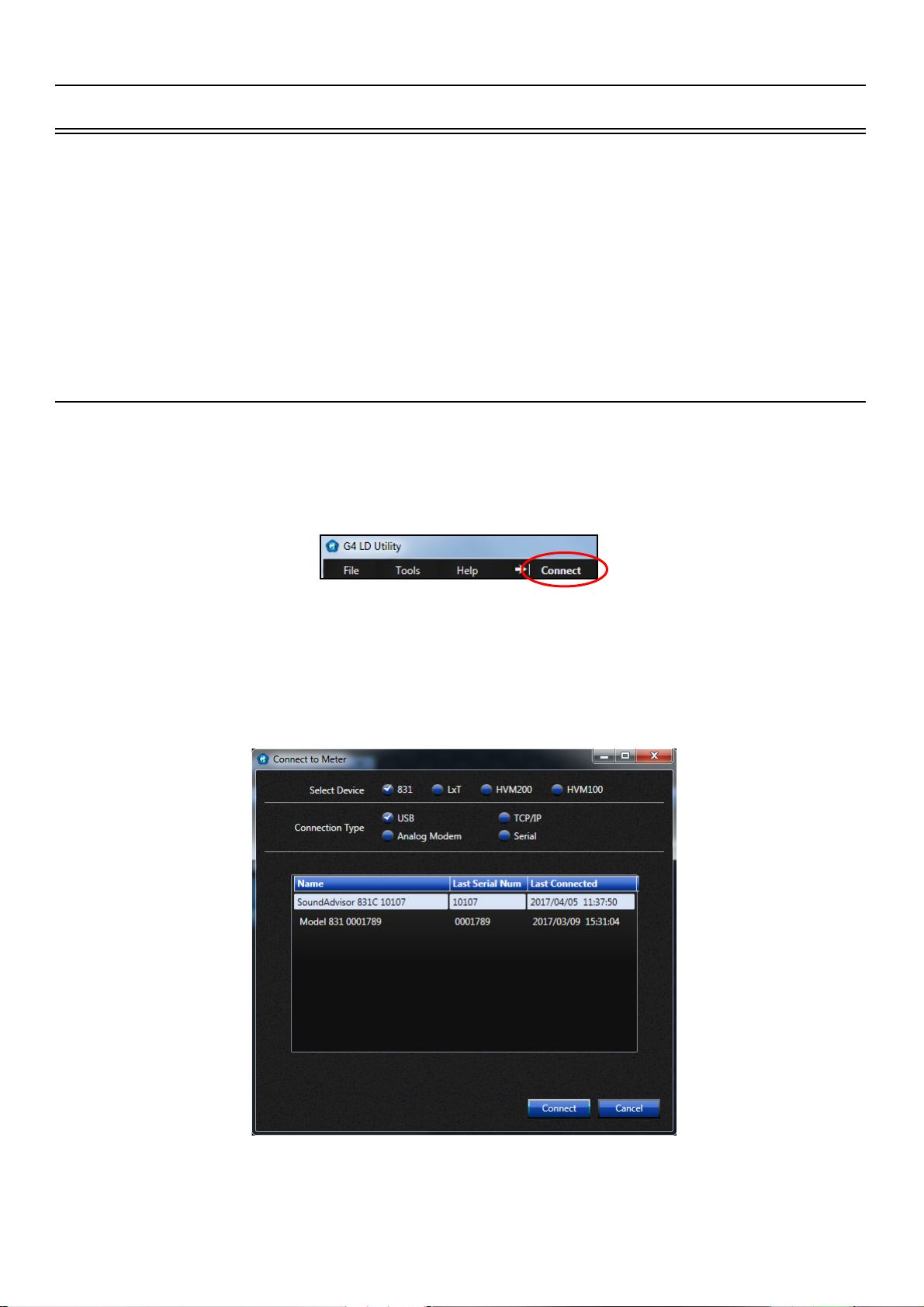
i.2.1 Connecting SoundAdvisor to G4
After installing G4 LD Utility, make your initial connection via USB cable from your instrument to PC. Press
the power button 0 on SoundAdvisor to turn the instrument on. Launch the G4 software and click Connect.
FIGURE I-1 G4 LD Utility Connect
In the Connect to Meter dialog box, select the device and connection type. Instruments that are detectable
via USB connection appear automatically in the list. When your instrument appears, select it and click
Connect when the instruments appear. G4 can be connected to multiple instruments through both TCP/IP
address and USB connection. For more information about G4 see the G4 LD Utility Manual.
FIGURE I-2 Connection To Meter
SoundAdvisor Model 831C i-3
Page 5
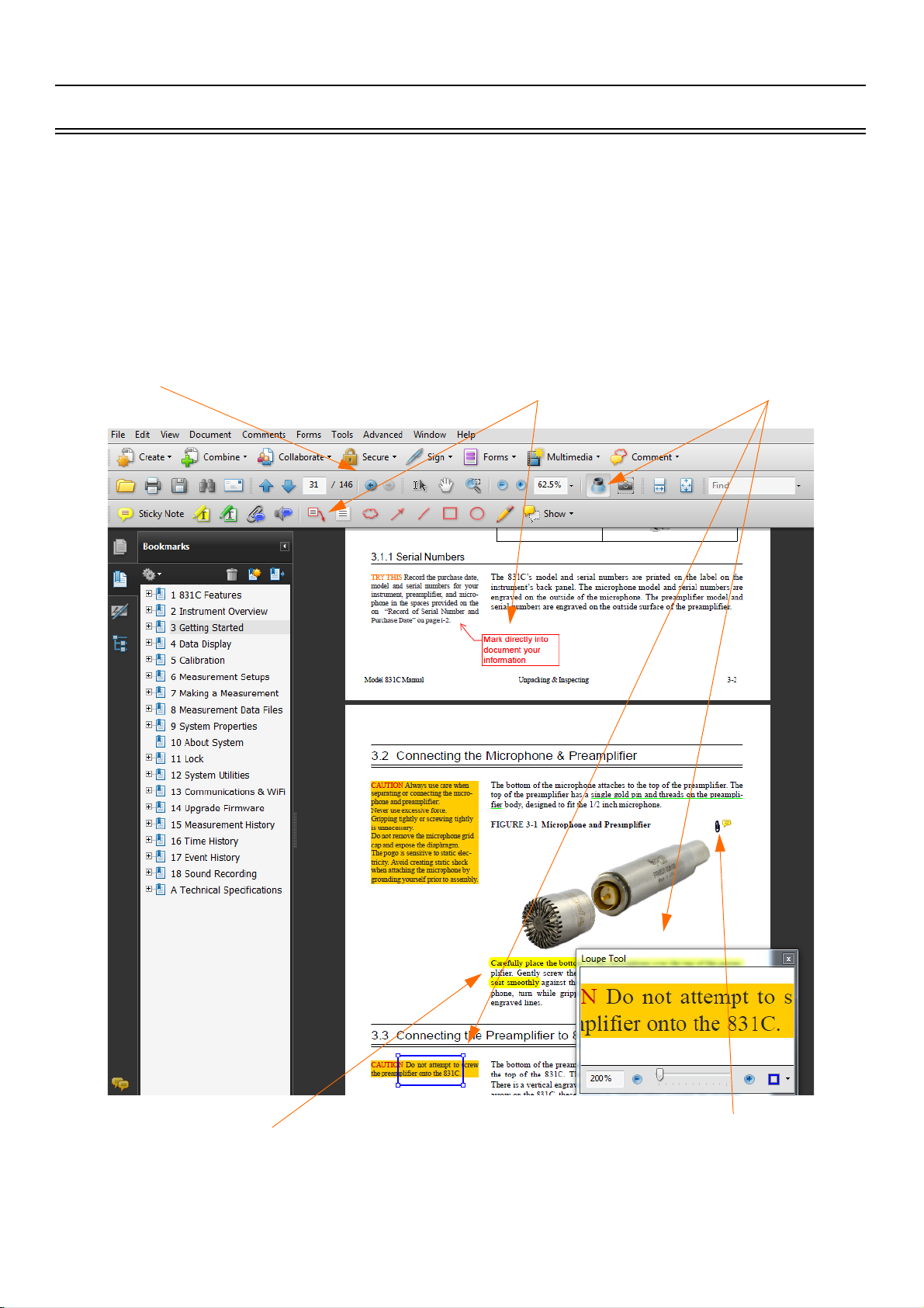
i.3 Using A Digital Reference Manual
Jump Back button for when
you go to a link and want to
return to your last place in the
document
Loupe Tool allows
for a quick zoom
window
Make text notes that point
directly to sections
Highlight or underline
any text
Create links to open other
documents you have that
relate to the content.
Larson Davis is committed to the green practices of limited paper waste. In this effort, we only offer
reference manuals in a digital PDF format. Digital notes and comments can be made in certain readers, and
you are encouraged to print any procedures or sections for quick references that fit your needs. Each page is
drafted on A4 size, and can be easily scaled to fit most printers. When printing set scaling to “Fit to Printable
Area”.
FIGURE I-3 PDF View on Adobe Acrobat Pro
SoundAdvisor Model 831C i-4
Page 6

Table of Contents
Module 1 SoundAdvisor Features 1-1
1.1 Overview ........................................................................................................................1-1
1.2 Basic Operations ............................................................................................................1-1
1.3 Applications .................................................................................................................... 1-2
1.4 Hardware Features ......................................................................................................... 1-2
1.5 Performance Features .................................................................................................... 1-3
1.6 Available Options ...........................................................................................................1-3
1.7 Accessories ....................................................................................................................1-4
Module 2 Instrument Overview 2-1
2.1 Overview ........................................................................................................................2-1
2.2 Instrument ...................................................................................................................... 2-2
2.3 Keypad ...........................................................................................................................2-4
2.4 Microphones and Preamplifiers ...................................................................................... 2-6
2.5 Displays and Icons .........................................................................................................2-6
Module 3 Getting Started 3-1
3.1 Unpacking & Inspecting .................................................................................................. 3-1
3.2 Connecting the Microphone & Preamplifier ....................................................................3-3
3.3 Connecting the Preamplifier to SoundAdvisor ................................................................ 3-4
3.4 Disconnecting the Preamplifier .......................................................................................3-4
3.5 Powering the SoundAdvisor ...........................................................................................3-4
3.6 Turn the SoundAdvisor ON ............................................................................................ 3-8
3.7 Long Term Storage of SoundAdvisor ........................................................................... 3-10
Module 4 Data Display 4-1
4.1 Overview ........................................................................................................................4-1
4.2 Data Labels ....................................................................................................................4-2
4.3 Live Displays .................................................................................................................. 4-2
4.4 Overall Displays ............................................................................................................. 4-6
4.5 Session Log Tab .......................................................................................................... 4-16
4.6 Adjust Graph Scale ...................................................................................................... 4-17
Module 5 Calibration 5-1
5.1 Calibration Overview ...................................................................................................... 5-1
5.2 Calibration Displays ........................................................................................................5-2
5.3 Choosing a Calibrator ..................................................................................................... 5-5
5.4 Performing a Calibration ................................................................................................. 5-6
Module 6 Measurement Setup 6-1
6.1 Overview ........................................................................................................................6-1
6.2 Setup Manager ...............................................................................................................6-2
6.3 Default to LD Default Setup ............................................................................................6-9
6.4 User Defined Setup ........................................................................................................ 6-9
6.5 Exiting the Setup Manager ...........................................................................................6-10
Module 7 Making a Measurement 7-1
7.1 Overview ........................................................................................................................7-1
7.2 Before You Start ............................................................................................................. 7-2
7.3 Performing the Measurement ......................................................................................... 7-4
7.4 Storing the Measurement ............................................................................................... 7-7
7.5 Low Level Sound Fields ................................................................................................. 7-8
Module 8 Measurement Data Files 8-1
8.1 Overview ........................................................................................................................8-1
I831C.01 Rev C Supporting Firmware Version 3.0.2 ii-1
Page 7

8.2 Data Storage Preferences .............................................................................................. 8-1
8.3 Data File Manager ..........................................................................................................8-2
8.4 USB Drive Storage ......................................................................................................... 8-4
8.5 File Naming System ....................................................................................................... 8-6
8.6 Out Of Memory ...............................................................................................................8-7
8.7 Access Limited ...............................................................................................................8-7
Module 9 System Properties 9-1
9.1 Overview ........................................................................................................................9-1
9.2 Device ............................................................................................................................9-2
9.3 Time ...............................................................................................................................9-2
9.4 NTP ................................................................................................................................ 9-3
9.5 Power .............................................................................................................................9-3
9.6 Preferences .................................................................................................................... 9-6
9.7 Localization .................................................................................................................... 9-9
9.8 Displays ........................................................................................................................9-10
9.9 Options .........................................................................................................................9-11
9.10 Network ........................................................................................................................9-11
9.11 Email ............................................................................................................................9-12
9.12 Other ............................................................................................................................9-13
9.13 Set Reference Spectra .................................................................................................9-14
Module 10 About System 10-1
Module 11 Lock 11-1
11.1 Overview ......................................................................................................................11-1
11.2 Lock Meter .................................................................................................................... 11-1
11.3 Lock Modes .................................................................................................................. 11-2
11.4 Allow Calibration When Locked .................................................................................... 11-3
11.5 Constraints ................................................................................................................... 11-4
11.6 Unlock ..........................................................................................................................11-4
Module 12 System Utilities 12-1
12.1 Bad Flash Blocks ..........................................................................................................12-1
Module 13 Communications & WiFi 13-1
13.1 Communication ............................................................................................................ 13-1
13.2 Connecting to an Ethernet Port .................................................................................... 13-2
13.3 WiFi ..............................................................................................................................13-2
Module 14 Upgrade Firmware 14-1
14.1 G4 LD Utility .................................................................................................................14-1
14.2 Upgrading SoundAdvisor Firmware ............................................................................. 14-1
14.3 Upgrading Options ....................................................................................................... 14-3
14.4 Enabling/Disabling Optional Firmware ......................................................................... 14-4
Module 15 Measurement History 15-1
15.1 Overview ......................................................................................................................15-1
15.2 Enabling Measurement History .................................................................................... 15-1
15.3 Setting up the Measurement ........................................................................................ 15-1
15.4 Making a Measurement ................................................................................................ 15-4
15.5 Viewing Measurement Data ......................................................................................... 15-5
15.6 Storing Measurement History ....................................................................................... 15-6
Module 16 Time History 16-1
16.1 Overview ......................................................................................................................16-1
16.2 Metrics Logged .............................................................................................................16-1
16.3 Enabling Time History .................................................................................................. 16-3
SoundAdvisor Model 831C ii-2
Page 8

16.4 Setting up the Measurement ........................................................................................ 16-3
16.5 Making a Time History Measurement ........................................................................... 16-5
16.6 Markers ........................................................................................................................16-5
16.7 Viewing Time History Data ........................................................................................... 16-6
16.8 Storing Time History ..................................................................................................... 16-8
Module 17 Event History 17-1
17.1 Overview ......................................................................................................................17-1
17.2 Enabling Event History ................................................................................................. 17-1
17.3 Setting up the Measurement ........................................................................................ 17-2
17.4 Making an Event History Measurement ....................................................................... 17-5
17.5 Viewing Event History Data .......................................................................................... 17-5
17.6 Storing Event History .................................................................................................... 17-7
17.7 Triggering Method ........................................................................................................ 17-7
Module 18 Sound Recording 18-1
18.1 Overview ......................................................................................................................18-1
18.2 Enabling Sound Recording Option ............................................................................... 18-1
18.3 Create Setup File ......................................................................................................... 18-1
18.4 Manual Sound Recording ............................................................................................. 18-2
18.5 Marker Sound Recording ............................................................................................. 18-3
18.6 Event Sound Recording ............................................................................................... 18-4
18.7 Sound Recording Playback .......................................................................................... 18-7
18.8 Storing Sound Recordings ........................................................................................... 18-8
Appendix A Technical Specifications A-1
A.1 Overview ....................................................................................................................... A-1
A.2 SoundAdvisor Model 831C Instrument Platform ........................................................... A-1
A.3 SoundAdvisor Model 831C Base Software ................................................................... A-4
A.4 SoundAdvisor Model 831C Octave Band Analysis Software – Option 831C-OB3 ........ A-7
A.5 SoundAdvisor Model 831C Event Logging Software – Option 831C-ELA .................. A-13
A.6 SoundAdvisor Model 831C Time History Software – Option 831C-LOG .................... A-14
A.7 Frequency Response .................................................................................................. A-15
Appendix B Measuring IEC61672-1 B-1
B.1 Overview ....................................................................................................................... B-1
B.2 Section 9.3 .................................................................................................................... B-1
Appendix C Glossary C-1
C.1 Overview ....................................................................................................................... C-1
C.2 Glossary of Terms ......................................................................................................... C-1
SoundAdvisor Model 831C ii-3
Page 9

Module
1.1 Overview ............................................................................................................... 1-1
1.2 Basic Operations ................................................................................................... 1-1
1.3 Applications ...........................................................................................................1-2
1.4 Hardware Features ...............................................................................................1-2
1.5 Performance Features ..........................................................................................1-3
1.6 Available Options .................................................................................................. 1-3
1.6.1 Purchase-Required Options .....................................................................1-3
1.7 Accessories ...........................................................................................................1-4
1.7.1 Optional Accessories ...............................................................................1-4
1 SoundAdvisor Features
1.1 Overview
TAKE NOTE The “C” in 831C
stands for color.
1.2 Basic Operations
TRY THIS Explore the
interface, press buttons, change
settings, and test the
operations.
The SoundAdvisor Model 831C (the SoundAdvisor, 831C, or meter) is a
Class 1 acoustic monitoring instrument with a full-color touch screen that
measures noise frequency, sound pressure level, and community and
environmental sound.
G4 LD Utility (G4) software connects your meter through USB 2.0 highspeed and other wired and wireless methods to your PC. With G4 you can
calibrate the meter, create setup files, download measurements, and
analyze the results.
The SoundAdvisor performs the following operations:
• Measures sound: stop, pause, and resume measurement
• Display broadband and spectral sound values on a full-color
display screen
• View live and stored data while a measurement is in process
• Log simultaneously to time, statistical measurement and event
histories
• Use markers to annotate portions of time histories, including voice
annotation
• Automatically back up data to prevent data loss on power failure
• Calibrate using a Precision Acoustic Calibrator, and store
calibration history
SoundAdvisor Model 831C Overview 1-1
Page 10

1.3 Applications
• Time stamping for L
• Sync clock with PC, attached GPS, or Network Time Protocol
(NTP)
• Create multiple Setup configurations using the Setup Manager
• Record audio in .wav and .ogg formats with event, manual, or
time-based triggers
The SoundAdvisor monitors:
• City noise
• Construction noise
• Airport noise
• Nuisance noise
• Noise ordinance compliance
max
, L
min
, L
peak-(max)
single event metrics.
1.4 Hardware Features
The SoundAdvisor is a precision integrating sound level meter with the
following hardware features:
TAKE NOTE Up to 32GB USB
memory can be purchased
from Larson Davis as an
option.
• Wind farm noise
• 2 GB internal industrial grade data memory
• 240 x 320 full-color graphic LCD display with touchscreen user
interface
• Quiet Touch elastomeric keypad
• 4-AA batteries provide upwards of 8 hours operating time, usable
with NiMH, photo-lithium, lithium-Ion, and alkaline cells
• AC/DC output jack with full dynamic range option
• Compatible with 61 m (200 ft.) microphone extension cable (full
scale to 20 kHz)
• Dust resistant durable plastic case with lanyard and tripod mount
(tripod not included)
• USB 2.0 high-speed host connector for mass storage, weather
sensors, USB headset, and WiFi communication devices
• USB 2.0 high-speed peripheral connector for control and data
download by a PC
• I/O connector for power, weather transducers, logic input/output,
and preamplifier communications
SoundAdvisor Model 831C Applications 1-2
Page 11

1.5 Performance Features
• Large dynamic range > 120 dBA
• RMS Detectors: Slow, Fast & Impulse
• RMS Frequency Weighting: A, C & Z
• Peak Frequency Weighting: A, C & Z
• Any LevelTM Simultaneous measurement and display of Max and
Min sound pressure levels (Slow, Fast and Impulse detectors), plus
Leq and Peak levels, all with A, C and Z frequency weighting
• Weather Measurements (Wind Speed and Direction, Temperature,
and Humidity with SEN03x)
• Multiple language support: English, French, Italian, German, and
Spanish
• Field-upgradeable firmware
1.6 Available Options
LEARN MORE To purchase
options, see “Contact Larson
Davis” on page ii-2.
The SoundAdvisor is delivered with all firmware options available at the
time of manufacture already installed. However, only those options which
have been purchased are enabled. Any of the other firmware options can
be enabled at a later date, following purchase, using a file delivered from
Larson Davis.
1.6.1 Purchase-Required Options
831C-LOG
Time History data logging with periods from 2.5 ms to 24 hours
831C-OB3
Real-time 1/1 & 1/3 Octave Frequency Analysis
831C-ELA
Measurement History for the manual or timed storage of statistical data,
and exceedance-based Logging Analysis with Events
831C-SR
Make event based and manual sound recordings that can be sent via email
or SMS and stored in the measurement data.
831C-MSR
Measurement History for the manual or timed storage of statistical data,
and exceedance-based Logging Analysis with Events, with all sound
recording capabilities
831C-SW
Make direct USB communication with Sierra Wireless RV50 gateway.
SoundAdvisor Model 831C Performance Features 1-3
Page 12

1.7 Accessories
TAKE NOTE Some of these
options may not be provided
with systems designed for
specific applications.
Microphone Preamplifier
Microphone
Software CD
Unless otherwise noted, the SoundAdvisor is delivered with these
standard accessories:
PRM831
or
PRM2103
377B02 1/2” free-field prepolarized microphone, 50 mV/Pa, providing
performance conforming to Class 1 sound level meter standards
or
377C20 1/2” random incidence prepolarized microphone, 50 mV/Pa,
providing performance conforming to Class 1 sound level meter standards
G4 LD Utility Software for setup, measurement, download, and data
viewing through CBL138 USB, TCP/IP, serial, or analog modem
connections
Accessory Kit
Other
1.7.1 Optional Accessories
Microphones
831-ACC includes:
• 831-CCS Hard Shell Case
• PSA029 Universal AC USB Power Adaptor
• CBL138 USB to mini-B cable, 1.8 m
• WS001 3 1/2” Windscreen
• 4 Rechargeable AA NiMH batteries
Lanyard
• 377C01 1/4” free-field prepolarized microphone, 2 mV/Pa, for
higher level and/or higher frequency measurements (ADP043
adaptor required)
• 377C10 1/4” pressure prepolarized microphone, 1.0 mV/Pa, for
higher level and/or higher frequency measurements (ADP043
adaptor required)
SoundAdvisor Model 831C Accessories 1-4
Page 13

Microphone Preamplifiers
Environmental Protection
• 426E01 1/2” ICP Low Noise Microphone Preamplifier (requires
adaptor ADP074)
• PRM2103 Outdoor Microphone Preamplifier
• PRM426A12 Outdoor Microphone Preamplifier
EPS2116 Environmental Shell
Protects microphone and preamplifier from rain and wind with mounting
options for pipes, poles, and most tripods
EPS030-831
Weather-proof enclosure for remote noise monitoring; includes battery
NMS/EPS043
Weather proof enclosure for remote noise monitoring
NMS044
Solar powered noise monitoring system for outdoor, long-term, and
unattended sound monitoring
Weather Data Acquisition
• 831-INT 831 Interface Unit for use with 426A12 Outdoor
Microphone Preamplifier and weather sensors
Communication
• DVX012, 013, 014, 015
• DVX008A USB to RS232, 9 Pin Adaptor
• 831-INT-ET 831-INT with integrated Ethernet capability
GPS
GPS001 GPS Receiver, USB Magnetic Mount
Equivalent Electrical Impedance Adaptor
An equivalent electrical impedance adapter can be used in place of the
microphone when very high impedance measurements need to be made
and the instrument is being tested electrically. The adapter is simply a
series capacitor with the same capacitance as the microphone it is
replacing. The following adapters are available. If square wave pulse
measurement is to be performed, then the adapter must also be used with a
100 kHz, low pass, T filter.
• ADP002 6.8pF BNC Input Adaptor for 1/4 in., 7pF microphone
equivalent
• ADP090 12pF BNC Input Adaptor for 1/2 in., 12pF microphone
equivalent
• ADP092 BNC In-Line Low Pass Filter 75kHz
SoundAdvisor Model 831C Accessories 1-5
Page 14

Cables
Extension and Interface Cables
• Microphone Extension Cable: EXCXXX (shielded), where XXX
is the length in feet (XXX = 010, 020, 050, 100 and 200 available)
• CBL138 USB Cable
• CBL139 AC/DC Output Cable
Cables for Environmental Monitoring
• CBL152 Cable; 426A12 to 831 Signal, 20’
• CBL153 Cable; 426A12 to 831-INT Control, 20’
• CBL154 Cable; 426A12 to 831C Control, 20’
• CBL203 Cable; PRM2103 to 831Control, 20’
• CBL208 Cable; PRM2103 to 831-INT Control, 20’
Cable for use with PSA027 Universal Input Power Supply AC
Power Adaptor
• CBL140 Cable; 831 Power, 2.5 mm JACK, 1’
Power Supply
Tripods
• PSA027 Universal 90-240 AC Power Adaptor providing power
from electrical outlet, used to power the SoundAdvisor in
conjunction with CBL140, CBL145 or CBL154. 1.25 A,
2.5X5.5X14 mm
• BAT015 External battery holder for the 831, holding 4 or 8 Dsized alkaline 1.5 volt batteries to extend run time
• TRP001 Instrument/Camera Tripod with ADP032 1/2 in.
microphone clip used with EPS2116
• TRP002 Microphone Stand with Boom
• TRP003 Support Tripod, heavy duty, can be used with EPS029,
EPS030 and EPS2116
• ADP091 Mounting adapter, 426A12 TO TRP003
• TRP019 Permanent 17' tilt down pole.
• TRP020-06 Heavy duty 6' tripod
• TRP020-10 Heavy duty 10' tripod
• TRP020-15 Heavy duty 15' tripod
• TRP020-20 Heavy duty 20' tripod
Other Hardware
Calibrators
• CAL200 Class 1 Sound Level Calibrator, 94/114 dB @ 1 kHz
SoundAdvisor Model 831C Accessories 1-6
Page 15

Optional Software
• CAL250 Class 1 Sound Level Calibrator, 114 dB @ 250 Hz
Soft Case
CCS032 pouch with belt clip
DNA (Data Navigation and Analysis) software
SoundAdvisor Model 831C Accessories 1-7
Page 16

Module 2 Instrument Overview
2.1 Overview ............................................................................................................... 2-1
2.2 Instrument ............................................................................................................. 2-2
2.3 Keypad .................................................................................................................. 2-4
2.3.1 Navigating and Selecting ......................................................................... 2-4
2.3.2 Basic Run Function .................................................................................. 2-5
2.3.3 Entering Text ............................................................................................ 2-5
2.4 Microphones and Preamplifiers .............................................................................2-6
2.5 Displays and Icons ................................................................................................ 2-6
2.5.1 Measurement Data Tabs ..........................................................................2-7
2.5.2 Pages ....................................................................................................... 2-8
2.5.3 Status Bar Icons ....................................................................................... 2-9
2.5.4 Display Menus ........................................................................................ 2-13
2.1 Overview
The SoundAdvisor Model 831C accomplishes all tasks related to sound
monitoring. The SoundAdvisor is a reliable and diversely competent
meter. With the SoundAdvisor, you can:
• Measure all area sound
• Stream and record audio continuously or for events using sample
rates up to 51.2 ksps in compressed or uncompressed format
• Communicate with via USB, Ethernet, cellular, or WiFi
• Operate completely from the device itself, or remotely using G4
LD Utility software
• Easily expand memory using USB memory
• Automatically synchronize the clock with Network Time Protocol
(NTP) or GPS for optimal accuracy
• Select desired color theme on the full-color graphic LCD display
with touchscreen user interface
This module describes the hardware and visual components that make up
the SoundAdvisor.
SoundAdvisor Model 831C Overview 2-1
Page 17
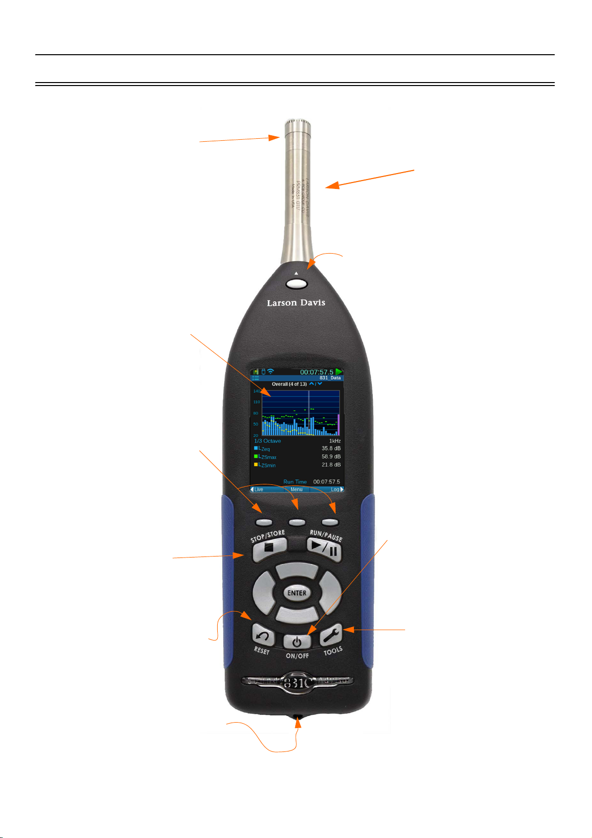
2.2 Instrument
Standard 1/2” free field
or random incidence
microphone
Release button to disconnect
the preamp from the meter
240 x 320 full-color graphic
LCD display with touchscreen
user interface (shown with
Dark color theme)
Display navigation
softkeys
Multicolor backlit keypad
Tools button leads
to system set-up
information
On/Off button is
also a one-touch
power control
access
Reset/Clear Measurement
USB Auxiliary port,
AC/DC output jack,
and I/O connectors
PRM831
Preamplifier
FIGURE 2-1 SoundAdvisor Instrument Overview (front)
SoundAdvisor Model 831C Instrument 2-2
Page 18
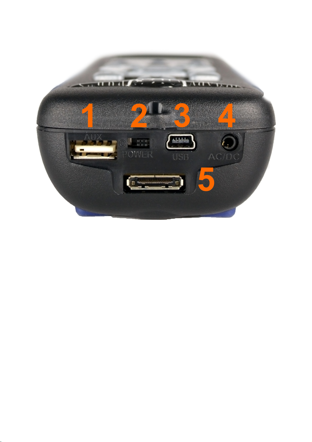
FIGURE 2-2 Instrument Overview (bottom)
CAUTION DO NOT use the
hardware power switch to turn the
SoundAdvisor ON or OFF. This may
cause data to be lost. The purpose of
this switch is to disconnect the
batteries for storage (1 to 2 weeks). If
any longer, then remove the batteries
from the meter.
CAUTION The AC/DC jack is not a
headphone jack.
1. AUX connector intended for use with USB mass storage, cellular &
dial-up modems, GPS, headphones, speakers, and future devices.
2. Hardware Power Switch when set to “ 0 ” completely powers down
the SoundAdvisor for storage. Set to “ | ” for instrument operation.
3. USB Interface 2.0 peripheral full-speed port used for communication,
full control, and downloading of data to PC. The PSA029 external
power supply may be connected here. The maximum USB cable
length is 1m and the cable is part number CBL138.
4. AC/DC 2.5 mm Output jack for analog AC/DC output signals.
5. The I/O Connector for peripherals and external power is typically
used for external devices.
SoundAdvisor Model 831C Instrument 2-3
Page 19
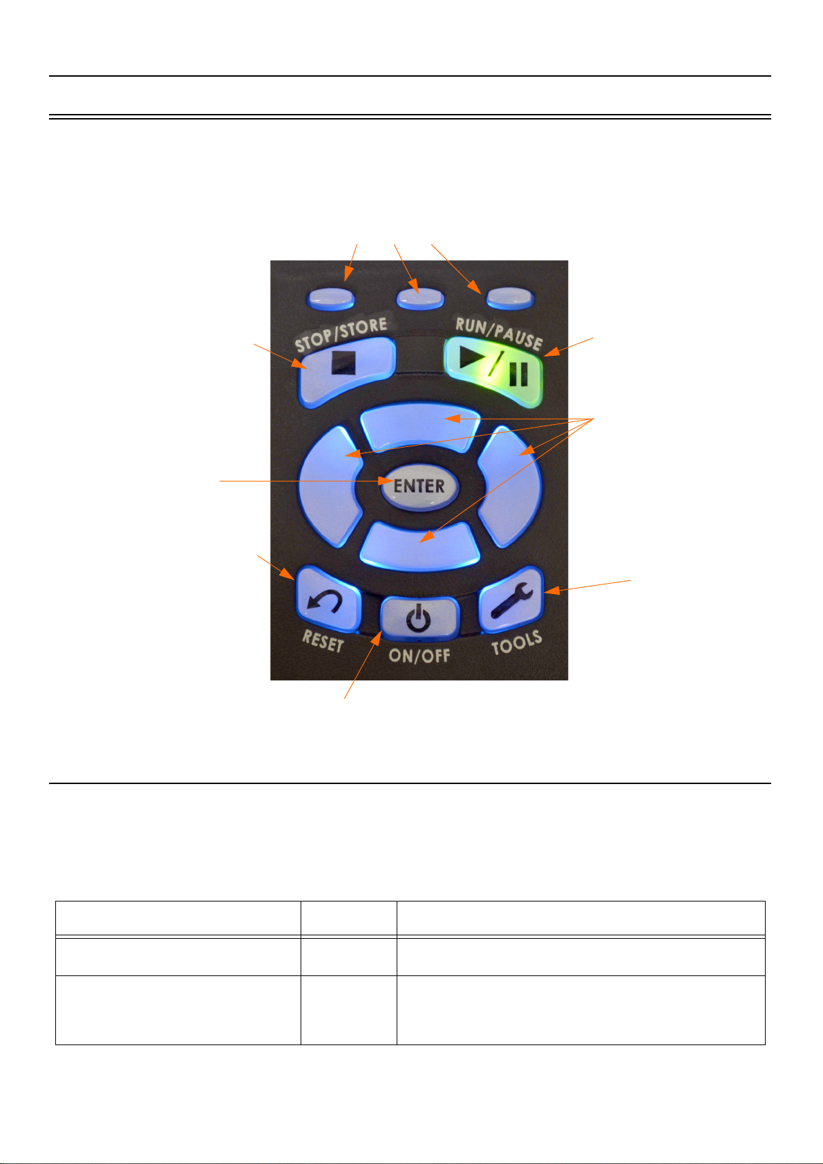
2.3 Keypad
Arrow Keys
Up, Down, Right, Left
Reset a measurement
Power Control
Tools menu
Stop or Store a measurement Run or Pause a
measurement
Select or Enter
The SoundAdvisor has 13 buttons that are used to start, stop, or pause
measurement, navigate display, and safely power the meter off.
FIGURE 2-3 SoundAdvisor Keypad
Softkeys:
Left, Center, Right
2.3.1 Navigating and Selecting
To navigate the display on the meter, you can utilize the touch-screen
feature and simply press your selection directly on the screen using the tip
of your finger, or use the keypad.
Table 2.1 Navigating and Selecting
Action Key(s) Description
Navigate to tabs
Navigate to pages
/ /
8
2
SoundAdvisor Model 831C Keypad 2-4
Top left & right softkeys
Up & down arrow keys
Page 20

Table 2.1 Navigating and Selecting
Action Key(s) Description
Navigate within display (e.g.,
move highlighted octave band)
Access content specific menu
Exit a menu
Navigate up & down in a display
Make a selection
2.3.2 Basic Run Function
Table 2.2 Basic Run
4 6
/*/
*
5
5
The basic run measurement functions can be executed using the following
keys:
There are times when a content specific menu appear
on the screen. The associated top soft key will access
The top middle soft key can be used to close or save.
If you don’t want to save, press it, and then select no
The enter key can be used to move up and down on
The enter key can be used to make a selection
Left & right arrow keys
that menu.
to exit.
certain pages
Action Key(s) Description
Initiate a run
Pause a run
Stop measurement
Store data file
Reset measurement
2.3.3 Entering Text
9
9
7
7
1
The SoundAdvisor allows for complete operation from the meter itself. In
instances where a text field will need to be edited, a keyboard will appear.
Navigate the keyboard using the arrow keys 2 8 up & down and 4
6 left & right. Use the 5 key to make a selection.
While the SoundAdvisor is running, press this
End a measurement during a run or pause
Pressing the stop/store button while the meter is
stopped will store the measurement data
Press the reset key to clear measurement
Start a measurement
button to pause
SoundAdvisor Model 831C Keypad 2-5
Page 21
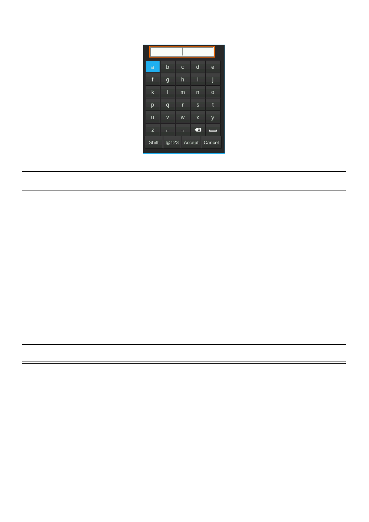
FIGURE 2-4 Keyboard
2.4 Microphones and Preamplifiers
The following microphone preamplifier is used with the SoundAdvisor:
LEARN MORE For information
on using the SoundAdvisor
with the PRM2103
preamplifier, see the PRM2103
Manual.
The following microphone are the most commonly used with the
SoundAdvisor:
2.5 Displays and Icons
The SoundAdvisor has a full-color, back-lit LCD touchscreen. The color
theme can be changed to dark or light from System Properties. See
“System Properties” on page 9-1.
• PRM831 1/2” Microphone Preamplifier
• 377B02 1/2” Free Field Microphone with nominal sensitivity of
50 mV/Pa
• 377C20 1/2” Random Incidence Microphone with nominal sensi-
tivity of 50 mV/Pa
• 377C01 1/4” Free Field Microphone with nominal sensitivity of
2.16 mV/Pa (ADP043 adaptor required)
• 377C10 1/4” Pressure Microphone with nominal sensitivity of 1
mV/Pa (ADP043 adaptor required).
When the SoundAdvisor is first powered ON, the Live screen is
displayed. When a measurement is in progress, the display is similar to
Figure 2-5 Live Main Screen.
SoundAdvisor Model 831C Microphones and Preamplifiers 2-6
Page 22
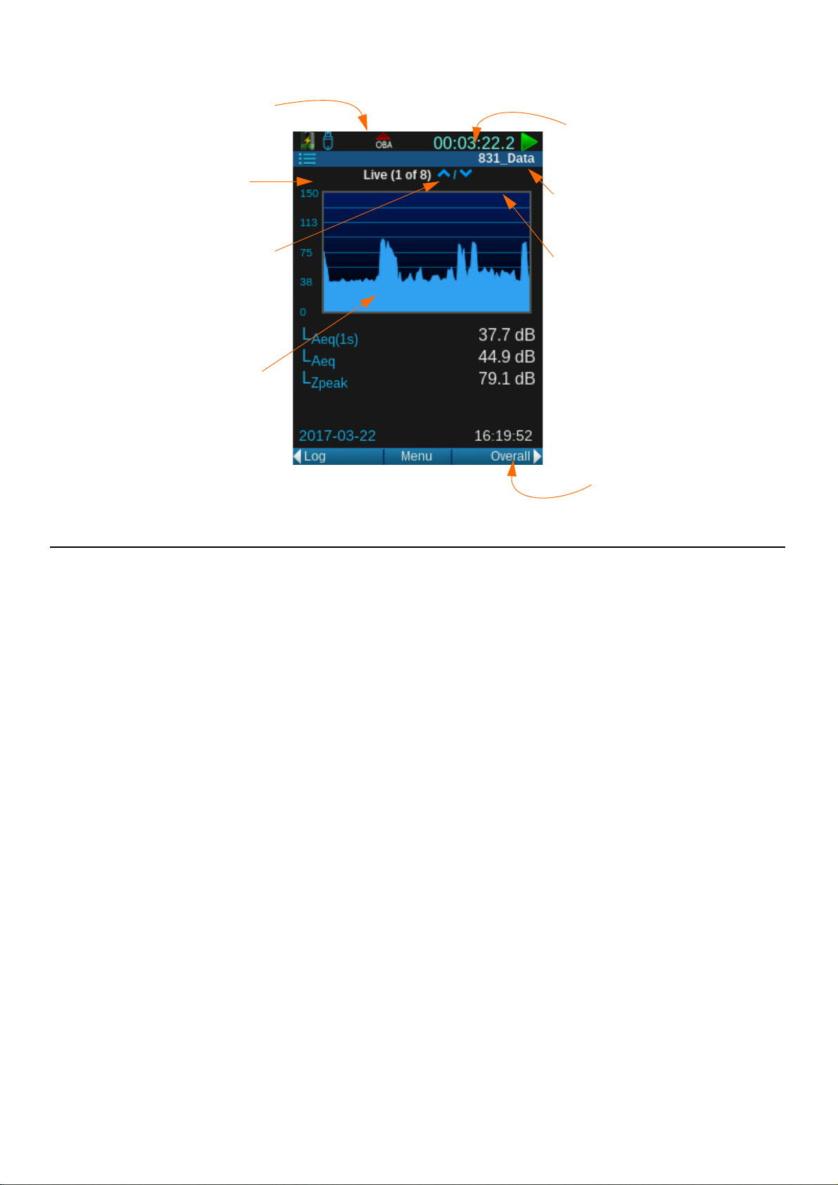
FIGURE 2-5 Live Main Screen
OBA Overload or
Under Range icon
Tools menu icon
Run time of current
measurement
Measurement status
Pages can be
accessed using the
up and down arrows
Measurement name
of current running
measurement
Data display
Session log,
Overall, and other
tabs can be accessed
using the right and
left softkeys
2.5.1 Measurement Data Tabs
TAKE NOTE There are seven
(7) tabs of measurement data.
Live, Overall, and Session Log
are default. To learn more
about additional tabs see
“Measurement Setup” on
page 6-1.
Measurement data is presented on three (3) main screens called “tabs”
that can be navigated using the top left/right softkeys:
Live
• Data is continuously displayed on this tab whether there is a mea-
surement running or not. Data displayed on the Live tab is not
stored in the meter.
• Up to 13 pages of Live Measurement data
Overall
• Represents data measured and averaged beginning from the time
the measurement was started until the elapsed time indicated at the
top of the display. If the measurement is stopped, the elapsed time
will stop. Pressing the run key again will continue the measurement. As long as there is no reset, the same measurement is continued.
• Up to 20 pages of Overall Measurement data
Session Log
LEARN MORE To learn more
about the Session Log, see
“Session Log Tab” on page 4-
16.
• A record of actions during a measurement. A time-stamped record
is made for every Run, Pause, Resume, Stop, and Sound Recording action. The source responsible for each action is also recorded.
Resetting and storing data will clear the session record.
SoundAdvisor Model 831C Displays and Icons 2-7
Page 23
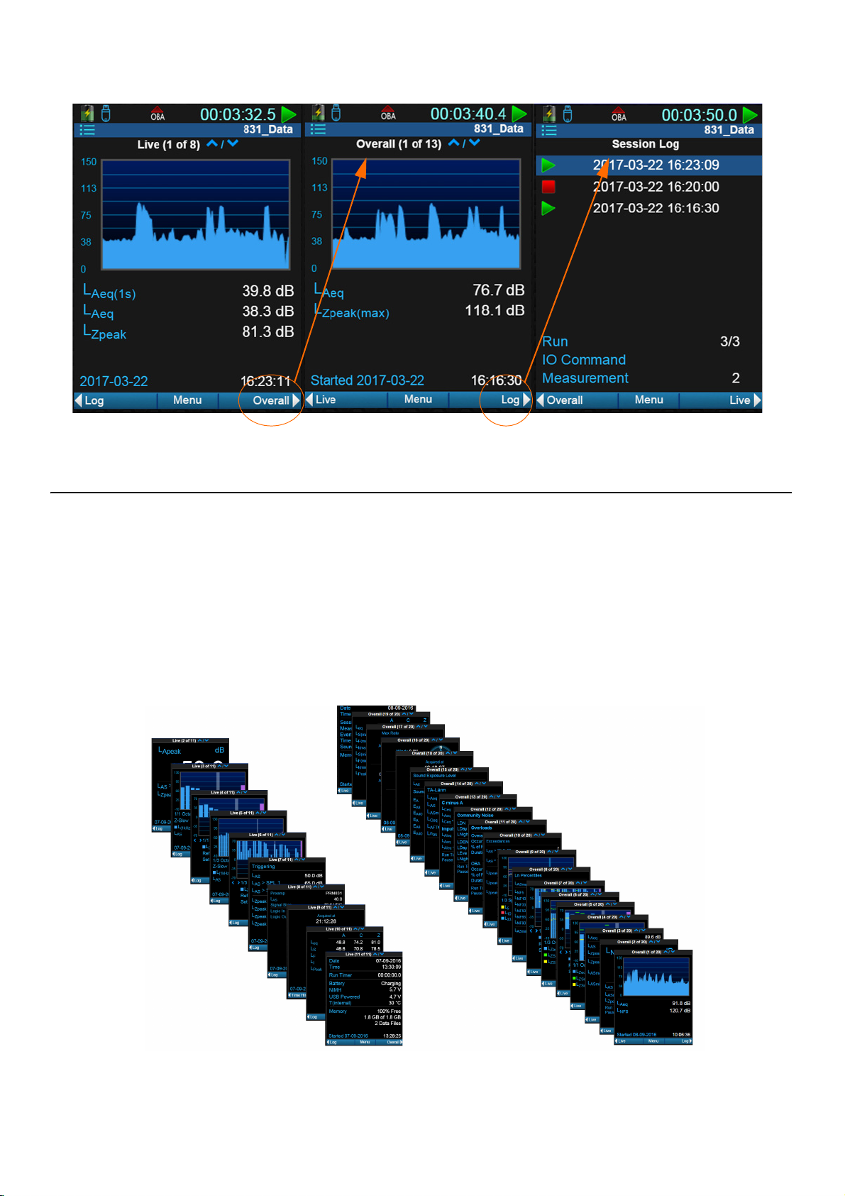
FIGURE 2-6 Measurement Data Tabs
Live Tab’s Pages
Overall Tab’s Pages
2.5.2 Pages
TAKE NOTE You may not have
all the pages available on the
SoundAdvisor. Additional
The Live and Overall tabs each have data displays called “pages” that
can be accessed using the up 8and down 2 arrow keys. Figure 2-7
shows all the pages available for these tabs.
pages of measurement data can
be purchased through Larson
Davis. “Contact Larson
Davis” on page i-2.
FIGURE 2-7 Live and Overall Pages
SoundAdvisor Model 831C Displays and Icons 2-8
Page 24
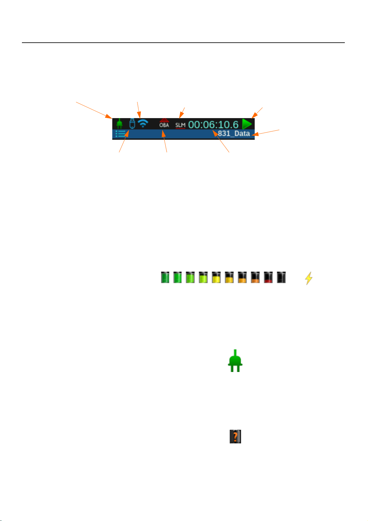
2.5.3 Status Bar Icons
Power Indicator
USB Memory Status
WiFi Status
OBA Indicator
SLM Indicator
Measurement Runtime
Run Status
File Name
FIGURE 2-8 Status Bar
Power Indicators
TAKE NOTE The battery icon
animates through the battery
state cycle while charging.
The top status bar will alert the user the status of the meter, measurement,
connection, and battery.
Battery
The battery icon indicates the state of the battery charge by color and
volume. Figure 2-9 Battery States indicates all the states of the battery
going from fully charged to depleted, if read left to right. The bolt symbol
appears over the battery icon if the battery is currently charging.
FIGURE 2-9 Battery States
External Power
The external power connection icon appears when the SoundAdvisor is
powered from an external power supply or via the USB port.
FIGURE 2-10 External Power Icon
Battery Status Pending
While the SoundAdvisor is checking the battery status, this pending icon
will appear until the battery percentage is determined.
FIGURE 2-11 Battery Status Pending Icon
SoundAdvisor Model 831C Displays and Icons 2-9
Page 25
WiFi Status
USB Memory Status
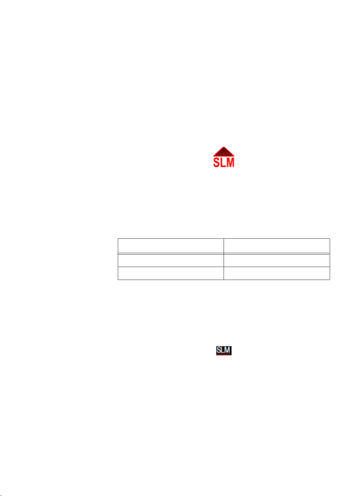
Input Overload Icon
See “WiFi” on page 13-2.
See “USB Drive Storage” on page 8-4.
When a signal from the preamplifier exceeds the calibrated input range of
the SoundAdvisor, the Input Overload icon will appear. While the
overload is present, the icon will flash.
If a measurement is running and an overload occurs, the icon shown
below will flash during the overload.
FIGURE 2-12 SLM Overload Icon
When the overload has been removed, the icon will still be present (not
flashing) to indicate that an overload has occurred during the
measurement. A reset will clear the icon from the display.
When using a microphone having a sensitivity of 50 mV/Pa, the input
overload will occur approximately as shown in Table 2.3.
Under Range Icon
Table 2.3 Input Overload Levels
Input Gain, dB Overload Level, dB Peak
0 143
20 123
When the signal from the preamplifier drops to the point where the noise
level of the instrument and the preamplifier influence the measurement,
an under range condition exists. When this happens the Under Range Icon
will appear.
FIGURE 2-13 Under Range Icon
As long as the under range condition exists, the icon will flash. When the
measured level no longer produces an under range condition, the icon will
be removed from the display.
At any time when a measured parameter is in an under range condition, its
numeric display will alter in color, as shown in Figure 2-14.
SoundAdvisor Model 831C Displays and Icons 2-10
Page 26
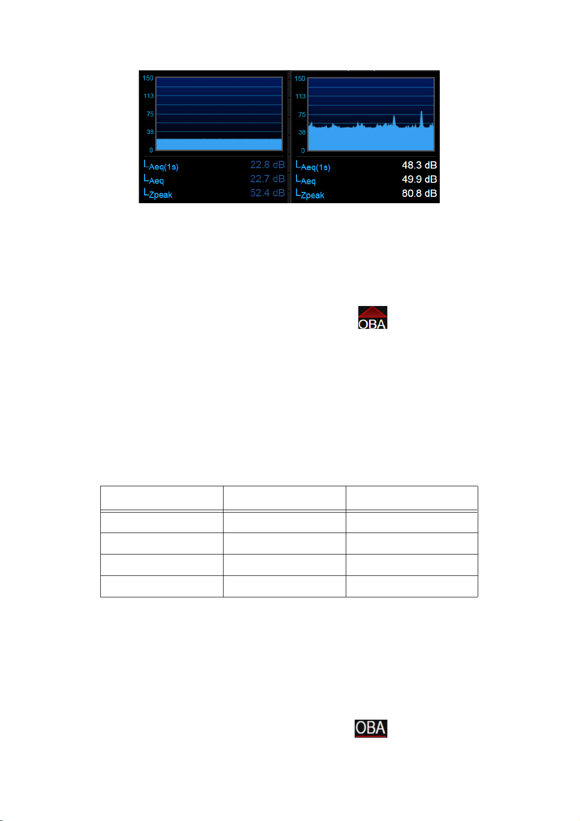
FIGURE 2-14 Under Range vs. Normal Range Data Display
Under Range Display Normal Range Display
OBA Overload Icon
If the input to the Octave Band Analyzer becomes overloaded, the OBA
Overload icon will appear to indicate the overload.
FIGURE 2-15 OBA Overload Icon
Table 2.4 OBA Overload Levels
Input Gain, dB OBA Range Overload Level, dB
0 Normal 143
20 Normal 123
0 Low 110
20 Low 90
OBA Under Range Icon
This icon operates similar to the Input Overload Icon shown in the above
section “Input Overload Icon”.
When the OBA Range property is set to Low, the OBA Overload Icon
will activate at a level 33 dB lower than it would had the OBA Range
been set to Normal.
When using a microphone having a sensitivity of 50 mV/Pa, the input
overload will occur approximately as shown in Table 2.4.
When the signal from the preamplifier drops to the point where the noise
level of the instrument and the preamplifier influence the measurement,
an under range condition exists.
When all filters of the OBA are “under range” the OBA Under Range
Icon appears.
FIGURE 2-16 OBA Under Range Icon
SoundAdvisor Model 831C Displays and Icons 2-11
Page 27
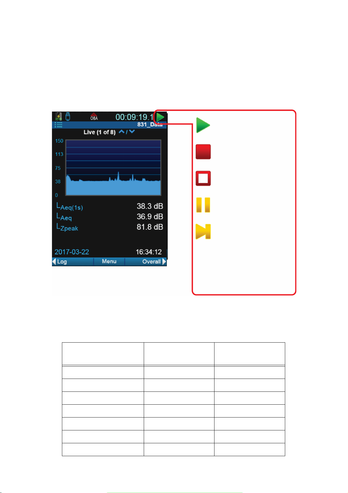
As long as this under range condition exists, the icon will flash. When the
Run
A measurement is currently
running.
Stop
A measurement is stopped.
Reset
A measurement reset has
occurred.
Run Pending
The meter is waiting for
filters and detector
initialization to complete
and will automatically start
the run when the system is
stable (typically less than 10
seconds).
Pause
The present run is paused.
measured OBA levels no longer produces an under range condition, the
icon will be removed from the display.
Measurement Status
The state the meter is currently in will be indicated by a measurement
status icon. The measurement status is indicated by five icons for the five
states: run, stop, reset, pause, run pending.
FIGURE 2-17 Measurement Status Icons
If touch-screen is enabled, or you are operating the SoundAdvisor
remotely, touching the icon will change the status with the following
results:
Table 2.5 Touch Icon Results
Measurement State Action
Resulting
Measurement State
Run Press Once Stop
Run Double Tap Pause
Pause Press Once Run
Stop/Reset Press Once Run
Stop/Reset Double Tap Store
Run Pending N/A N/A
Power Save Press Once Run
SoundAdvisor Model 831C Displays and Icons 2-12
Page 28
Analog Power Save Icon
LEARN MORE To learn more
about power saving options,
see “Power” on page 9-3.
When the SoundAdvisor is not connected to a PC, it can be put in a power
saving mode that shuts down the analog circuitry, including the
preamplifier, to save battery power. The power save icon will be
displayed in the location where the measurement status icons appear.
FIGURE 2-18 Analog Power Save Icon
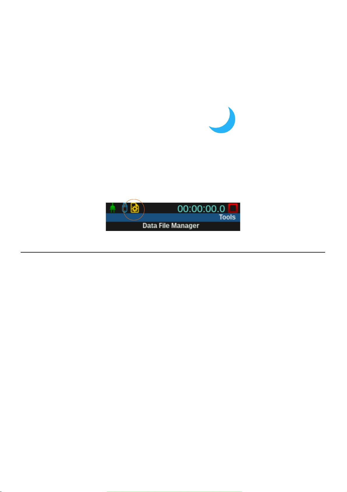
File Operation Icon
The file operation icon will appear on the status bar to indicate that a file
is currently being saved onto the USB, moved from the USB to meter, or
is being copied. All these operations are done in the Data File Manager,
see page 8-1. It is a standby icon that will disappear once the operation in
complete.
FIGURE 2-19 File Operation Icon
2.5.4 Display Menus
The SoundAdvisor features and functions are organized into three general
menus:
Main Menu
Accessed using the center softkey that indicates Menu
• Setup Manager
• Mark Sound Type
• Any Level Menu - Access on profile display by pressing 5
• Adjust Graph
• Print Screens (only available with printer inserted)
Tools Menu
Accessed using 3 Tools or the menu icon on the display
• Data File Manager
•Calibrate
• Setup Manager
• System Properties
• About
• Lock
SoundAdvisor Model 831C Displays and Icons 2-13
Page 29

Any Level Menu
FIGURE 2-20 Any Level Menu
• System Utilities
• Communication
• Setup WiFi (if available)
Power Control
Accessed by pressing the 0 once
• Battery Information
•Display
•Off
• Reboot
To select which sound level parameter is to be used for the 2nd numerical
value displayed, press the 5 to open the menu.
Setup Manager
TAKE NOTE A new setup file
can be created using G4 LD
Utility and then moved on to
the meter.
TRY THIS Name a
measurement file using the on
screen keypad that appears
once you select the
measurement name.
The Setup Manager is a platform that allows for measurements to be
made with preset settings in what are called “setup files” or “setups”.
From any tab or page on the meter, press the Menu soft key, select Setup
Manager. The first display is a list of the setup files currently available on
the meter. The Active setup is the current setup for all runs made. The
Default setup can be made active, and it cannot be removed or deleted.
Select Active and navigate to the different settings using top left and right
softkeys.
General
Name a measurement file, and add description.
SLM
Define the weightings, filters, and integration type for the measurement
sound levels.
OBA
Set the parameters for the real-time octave band frequency analysis.
SoundAdvisor Model 831C Displays and Icons 2-14
Page 30

TAKE NOTE
Enabling some
settings will open more pages
under the tabs in the data
display.
Ln
Define the Ln statistics.
Control
Define the way a measurement is performed, the timing, and the storage
of measurement history records.
LEARN MORE For more
information on the
Measurement Settings tabs and
pages, “Measurement Setup”
on page 6-1.
System Properties
LEARN MORE To learn more,
see “System Properties” on
page 9-1.
Time History
Enable the time history and select the metrics that are stored in the time
history.
Triggers
Define the levels at which noise exceedance events will be triggered
Event History
Define the timing and options for events.
Markers
Define the marker types and enable markers.
Day/Night
Define the time periods and level penalties for community noise metrics.
Sound
Set the quality of sound recording and enable its usage.
Weather
Set the weather station type and values of external transducers for the
measurement of wind speed, wind direction, temperature and humidity.
Power
Define battery type, if the external power source should charge the
battery, and features like auto-off, power-save, backlights, keypad
backlight, LCD brightness, and the external shutoff voltage.
Preferences
Set mic correction, auto-store, the AC output, reset properties, data
storage location, GPS mode, and the time zone correction.
Locale
Set language preference, decimal symbol, date format, and the units in
which the measurement is displayed.
Displays
Define the default start display, and toggle between tabs to hide or show
pages.
Options
Hide or show purchased options on the meter.
Network
View the 831 INT-ET IP address and the external Ethernet IP and MAC
addresses. Enable Watchdog is also on this page.
SoundAdvisor Model 831C Displays and Icons 2-15
Page 31

Email
Indicate recipients for email alerts.
Other
Set the Logic In, Logic Out, and heater.
Reference Spectra
Set values for the reference spectrum.
Device
Enter 30 characters per field of device information that will appear on the
About page under the Tools menu.
Time
Set timezone and date/time manually.
NTP
Add local or global NTP time servers for the most accurate time updates
on the meter.
SoundAdvisor Model 831C Displays and Icons 2-16
Page 32

Module 3 Getting Started
3.1 Unpacking & Inspecting ........................................................................................3-1
3.1.1 Serial Numbers ........................................................................................3-3
3.2 Connecting the Microphone & Preamplifier ........................................................... 3-3
3.3 Connecting the Preamplifier to SoundAdvisor ...................................................... 3-4
3.4 Disconnecting the Preamplifier ............................................................................. 3-4
3.5 Powering the SoundAdvisor ..................................................................................3-4
3.5.1 Battery Power ........................................................................................... 3-4
3.5.2 External Power ......................................................................................... 3-7
3.6 Turn the SoundAdvisor ON ................................................................................... 3-8
3.6.1 Turn the SoundAdvisor OFF .................................................................... 3-8
3.6.2 Power Display Pages ............................................................................... 3-8
3.7 Long Term Storage of SoundAdvisor ..................................................................3-10
3.1 Unpacking & Inspecting
TAKE NOTE Report any
damage or shortage
immediately to PCB
Piezotronics, Inc. See
“Contact Larson Davis” on
page i-2.
Table 3.1 SoundAdvisor Package
The SoundAdvisor is shipped in protective packaging. First, verify the
package contains the items listed below. Retain the packaging for safe
shipment for calibration service.
The SoundAdvisor should include:
SoundAdvisor
Model 831C
The 831C-FF and 831C-RI should include all from Table 3.1 and Table
3.2:
SoundAdvisor Model 831C Unpacking & Inspecting 3-1
PRM831 Microphone
Preamplifier
377B02 1/2 Inch
Microphone
Page 33

Table 3.2 831C-FF Package
831C-CCS Hard Shell Case
PSA029 Universal AC
Power Adaptor
WS001 3 1/2 inch
Windscreen
Lanyard
4 - AA NiMH batteries
G4 LD Utility Software
SoundAdvisor Model 831C Unpacking & Inspecting 3-2
Page 34

3.1.1 Serial Numbers
Table 3.2 831C-FF Package
Calibration Certification
TRY THIS Record the purchase
date, model and serial numbers
for your instrument,
preamplifier, and microphone
in the spaces provided on the
“Record of Serial Number and
Purchase Date” on page i-2.
The SoundAdvisor model and serial numbers are printed on the label on
the instrument’s back panel. The microphone model and serial numbers
are engraved on the outside of the microphone. The preamplifier model
and serial numbers are engraved on the outside surface of the
preamplifier.
3.2 Connecting the Microphone & Preamplifier
CAUTION Always use care
when separating or connecting
the microphone and
preamplifier:
Never use excessive force.
Gripping tightly or screwing
tightly is unnecessary.
Do not remove the microphone
grid cap and expose the
diaphragm.
The pogo pin is sensitive to
static electricity. Avoid
creating static shock when
attaching the microphone by
grounding yourself prior to
assembly.
The bottom of the microphone attaches to the top of the preamplifier. The
top of the preamplifier has a single gold pin and threads on the
preamplifier body, designed to fit the 1/2 inch microphone.
FIGURE 3-1 Microphone and Preamplifier
Carefully place the bottom of the microphone over the top of the
preamplifier. Gently screw the assembly together. The microphone body
will seat smoothly against the preamplifier body. When removing the
microphone, turn while gripping lightly the microphone body on the two
engraved lines.
SoundAdvisor Model 831C Connecting the Microphone & Preamplifier 3-3
Page 35

3.3 Connecting the Preamplifier to SoundAdvisor
Press here to
release preamp
from meter
CAUTION Do not attempt to
screw the preamplifier onto the
SoundAdvisor.
The bottom of the preamplifier has a 5 pin connector that fits snugly into
the top of the SoundAdvisor. The connectors are keyed for correct
alignment; There is a vertical engraved line on the preamplifier which
aligns with the arrow on the SoundAdvisor, these should be aligned
before inserting the preamplifier.
Insert the preamplifier into the mating connector on the SoundAdvisor.
Press the assemblies together until a small click is heard.
3.4 Disconnecting the Preamplifier
On the front surface of the SoundAdvisor, just below the preamplifier
connector, is a small button. Press and hold this button while gently
pulling the microphone/preamplifier assembly out of the SoundAdvisor.
FIGURE 3-2 SoundAdvisor Release Button
3.5 Powering the SoundAdvisor
To facilitate any task you may have with the meter, you can power the
SoundAdvisor with battery power or use an external power supply.
3.5.1 Battery Power
CAUTION Do not mix Alkaline and NiMH batteries.
CAUTION Do not mix batteries from different manufacturers.
CAUTION Replace all four batteries when installing fresh cells.
CAUTION The correct battery type must be specified in System Properties,
SoundAdvisor Model 831C Connecting the Preamplifier to SoundAdvisor 3-4
as described in “Battery Type” on page 9-3.
Page 36

CAUTION
Full Charge Low Charge
CAUTION A Session Log entry “Charging Stopped” can be resolved by
Do not charge non-rechargeable cells. Charge NiMH only.
checking the batteries and ensuring the correct battery type is selected.
Battery may be too old to charge. Battery may be read as incorrect battery
type, which may happen to fully discharged NiMH batteries. Use an
external battery charger to restore charge, then install in meter. The
batteries may be too hot or too cold, and the temperature may need to be
brought between 0° C - 45° C.
The SoundAdvisor is compatible with the following batteries:
• Energizer, Duracell, and other nationally recognized brands:
• AA nickel metal hydride (NiMH)
• AA Alkaline
• AA 1.5 Volt Lithium
Battery voltage is displayed on the Power Control screen that can be
accessed by pressing 0.
The battery icon indicates the state of the battery charge by the color and
fill of the battery icon.
FIGURE 3-3 Battery Status Icons
Low Battery
Install Batteries
As the battery nears end-of-life, the empty battery symbol will begin to
flash. When the battery is at the end-of-life, the SoundAdvisor will stop
running, save all data, and instrument status, then turn off. When the
SoundAdvisor is turned on again, with fresh batteries or an external
power supply, the unit returns to the state it was in when it shut down.
The battery compartment of the SoundAdvisor is on the back of the
instrument. When installing batteries, always insert 4 fresh AA batteries.
Regard polarity markings when inserted batteries.
SoundAdvisor Model 831C Powering the SoundAdvisor 3-5
Page 37

FIGURE 3-4 Insert Batteries
Charging Batteries using the SoundAdvisor
When using NiMH batteries and powering the SoundAdvisor from either
the computer (via USB port) or from the PSA029 power supply, or from
another external source, the batteries can be charged inside the
instrument.
TAKE NOTE The charge time to
completely recharge the cells is
about seven hours when the
instrument is powered off and
using USB to charge.
SoundAdvisor Model 831C Powering the SoundAdvisor 3-6
To turn on charging follow these steps:
Step 1 On the SoundAdvisor meter, go to Tools menu System
Properties. You can go to the Tools menu by pressing 3 on
the meter.
Step 2 Select battery type as NiMH.
Step 3 Charge will automatically set to On. If you do not want
your power source to charge your battery, set to Off.
Step 4 Select Save. A dialogue box will appear, select Ye s .
Page 38

Charge Status LED
3.5.2 External Power
USB Port Power
The charge status indicated by an LED on 0 are as follows:
• LED 0 continuously lit: Charging
• LED 0 not lit: Not charging
• LED 0 winking: Charging stopped (battery fault)
• LED 0 fast blinking: meter is powering up or shutting down
The SoundAdvisor can be powered from a variety of sources including:
• USB port from a computer
• USB port from PSA029 power supply
• I/O port from PSA027 power supply (using CBL140 or CBL154)
• From an external +10.8 to +30 Volt mains power source
The SoundAdvisor can be powered via the USB port with the PSA029
external power supply. The mini USB Type B connector is located on the
bottom of the meter.
CAUTION If the SoundAdvisor
is operated without batteries
installed and power is
interrupted, data may be lost.
Low Voltage Shutdown
Power Loss
With the PSA029 power supply connected and operating at rated
conditions, the SoundAdvisor will operate properly with or without
batteries installed.
The SoundAdvisor has a special feature to preserve the service life of an
external battery by preventing it from being discharged excessively.
When the battery voltage drops below the External Shutoff Voltage
(default value +10.8 volts), but remains above +10.2 volts for one minute,
the instrument will stop, save data and turn the SoundAdvisor off.
When the SoundAdvisor is powered from an external supply and the input
voltage falls below the indicated External Shutoff Voltage threshold, it
will power off. When the SoundAdvisor turns off due to a low battery, it
will automatically turn on 6 hours later and remain on if there is adequate
power. If the battery is still discharged, the SoundAdvisor will turn back
off and try again in another 6 hours. This feature is designed to allow the
SoundAdvisor to automatically restart when powering is lost do to low
solar situation or after an extended power outage.
Sudden Loss of External Voltage
If the external voltage is suddenly lost, for example when the external
supply is disconnected or when mains power fails and there is no external
battery, the SoundAdvisor will continue to run on internal batteries if they
are present and in good condition. If battery power is not present, the
SoundAdvisor will immediately switch to an internal recovery battery and
power down safely.
SoundAdvisor Model 831C Powering the SoundAdvisor 3-7
Page 39

External Power Icon
Without internal batteries, the external power is supplied through the USB
connector, the battery icon is replaced with the External Power icon, and
the meter is no longer using batteries to power.
If your meter has fully charged NiMH batteries and plugged in to a power
source, this icon will indicate that it is using power from the external
source, as well as not charging and not depleting any power from the
batteries.
FIGURE 3-5 External Power Icon
3.6 Turn the SoundAdvisor ON
After the SoundAdvisor is fully powered, either with an external power
source or fresh batteries installed, it is time to power the meter on.
Press the ON/OFF button 0 on the meter until the screen flashes and the
green LED light under the button turns on; It will take a second.
3.6.1 Turn the SoundAdvisor OFF
The SoundAdvisor can be turned safely OFF after accessing the Power
Control Page, see “Power Control Page” on page 3-8.
Alternatively, pressing and holding the power button for three seconds
will begin a safe shut down. Pressing and holding the power button for 10
seconds will force a hard shutdown.
3.6.2 Power Display Pages
There are several pages of power control and display.
Power Control Page
While the SoundAdvisor is powered on, the Power Control page can be
accessed by pressing the 0 power button once. This is the best way to
turn the meter off. Select Off to safely turn the meter off. Alternatively,
press and hold the 0 power button for three seconds and it will power
down safely.
SoundAdvisor Model 831C Turn the SoundAdvisor ON 3-8
Page 40

FIGURE 3-6 Power Control Page
Battery “quick look”
Manage the display
brightness and color
theme
You can then use the
top left softkey to
select Off to power
down the meter. This
is the recommended
method to powering
down the meter.
The right softkey will
reboot the meter
The current date and
time can easily be seen
on this page.
Voltage of the battery
and the USB external
power source can be
tracked here.
Checking the internal
temperature of the
meter periodically is
always good safety
practice.
The internal
memory
information is
also available on
the Power page.
Power Page in System Properties
LEARN MORE For more
information on the Power
page, see “Power” on page 9-
3.
To change the battery type, auto-off and other features use the Power
page. It can be accessed through the Tools System Properties.
Power Page on the Live Tab
FIGURE 3-7 Power Page on the Live Tab
Under the Live tab, on the last page (a shortcut would be to navigate “up”
instead of “down” on the Live tab to reach the Power page), there is the
Power page. On this page you can see all the battery, voltage, and
memory storage of the SoundAdvisor. Settings cannot be changed, only
viewed on this page.
SoundAdvisor Model 831C Turn the SoundAdvisor ON 3-9
Page 41

3.7 Long Term Storage of SoundAdvisor
CAUTION DO NOT use the
hardware power switch to turn
the SoundAdvisor OFF.
Permanent damage may occur.
Press the 0 once and then
select Off.
The Hardware Power Switch on the bottom of the SoundAdvisor
disconnects the batteries from the SoundAdvisor hardware. The real-time
clock will maintain its value while the switch is off. The power switch
prevents battery drain when the meter is not in use for an extended period
of time. If you plan to store the meter for more than two weeks, remove
the batteries.
If the switch is in the “ 0 ” position, the batteries are disconnected. After
installing batteries be sure to move the switch to the “ | ” position.
It should not be used to turn the SoundAdvisor ON and OFF. If the
Hardware Power Switch is used to turn the SoundAdvisor OFF, data may
be lost.
SoundAdvisor Model 831C Long Term Storage of SoundAdvisor 3-10
Page 42

Module 4 Data Display
4.1 Overview ............................................................................................................... 4-1
4.2 Data Labels ........................................................................................................... 4-2
4.3 Live Displays .........................................................................................................4-2
4.3.1 SLM Page ................................................................................................4-2
4.3.2 Big Digit Sound Level ...............................................................................4-3
4.3.3 Octave Band Analyzer ............................................................................. 4-3
4.3.4 Normalized Octave Band .........................................................................4-4
4.3.5 Triggering .................................................................................................4-5
4.3.6 Preamplifier Interface Page ...................................................................... 4-5
4.4 Overall Displays .................................................................................................... 4-6
4.4.1 SLM Display .............................................................................................4-6
4.4.2 Big Digit .................................................................................................... 4-6
4.4.3 Leq ........................................................................................................... 4-7
4.4.4 Octave Band Analyzer ............................................................................. 4-7
4.4.5 Normalized Octave Band .........................................................................4-9
4.4.6 Ln Percentiles ........................................................................................4-10
4.4.7 1/3 Spectral Ln ....................................................................................... 4-11
4.4.8 Exceedances ..........................................................................................4-11
4.4.9 Overloads ...............................................................................................4-12
4.4.10 Community Noise ................................................................................... 4-12
4.4.11 C Minus A Impulsivity Page ...................................................................4-13
4.4.12 TA-Lärm ................................................................................................. 4-13
4.4.13 Sound Exposure Level Page ..................................................................4-14
4.4.14 Metrics Matrix Page ...............................................................................4-14
4.4.15 Power Page ............................................................................................ 4-15
4.5 Session Log Tab ................................................................................................. 4-16
4.6 Adjust Graph Scale .............................................................................................4-17
4.1 Overview
The SoundAdvisor takes a measurement, and simultaneously displays
that same information in a variety of ways. At the same time you can take
a measurement and view:
• Sound metrics in real time
• Frequency of sound at each octave.
•Leq, LS, L
• Fast and Impulse detectors
• Temperature, GPS, and elevation that the sound was measured
• Sound weighted with specific values
of the overall or live sound
PEAK
SoundAdvisor Model 831C Overview 4-1
Page 43

4.2 Data Labels
L
Aeq
, 1 second
averaging, using
frequency weighting
and detector
selected in setup.
User-selected
SLM parameter
The duration is only
the duration of the
current measurement.
L
Zpeak
using frequency
weighting selected in
setup
4.3 Live Displays
The labels for sound metrics in the SoundAdvisor are designated by
international standards. For many displayed values, the frequency and
time weighting are indicated in the name of the metric.
For example, LAS is the A-weighted sound pressure level measured using
the Slow detector. Sound pressure level is often referred to as SPL.
LEARN MORE To learn about
the tabs, pages, and general
overview of the display of the
SoundAdvisor see “Displays
and Icons” on page 2-6.
TRY THIS Use the 8 or 2
keys to navigate up or down
through pages.
When the SoundAdvisor is turned ON, the default first display is the Live
tab. The measurements displayed on the Live tab are always active, realtime measurements. The displayed values are not controlled by the 9
(RUN/PAUSE) key. This allows you to view the current SPL without
disrupting any overall data.
For example, suppose you are making a measurement and an unwanted
event takes place, causing you to stop the measurement. With the
measurement stopped, you can monitor the actual level on the Live tab to
be certain that the residual effects of the unwanted event have died down
before beginning a new measurement.
4.3.1 SLM Page
FIGURE 4-1 Live Tab: Sound Level Profile Page
The profile page presents a recent history of L
Aeq
calculated for each
second. The graph presents the last 120 seconds of the measurement.
The first numerical level displayed, L
recently graphed 1 second value. The frequency weighting, and possibly
the detector, will correspond to those selected in setup for the RMS value.
(1s) in this example, is the most
Aeq
SoundAdvisor Model 831C Data Labels 4-2
Page 44

TRY THIS
Current value
Frequency weighting and
detector defined from the
setup, and updated once per
second.
The SPL1 Trigger Level
will turn orange when
exceeded
Peak exceedance will
gray out if it is under
range
Date
Current time on the
meter
While on this page,
press the 5 key, select a new
parameter and look where the
data is displayed.
User-Selected Parameter
FIGURE 4-2 User-Selected Menu
The 2nd numerical level display, L
in this example, corresponds to a
Aeq
user-selected parameter. The default value is LAS. The selection of this
value is described in “User-Selected SLM Parameter” on page 5-3.
The 3rd numerical level displayed, L
in this example, is the current
Zpeak
measurement from the 1s peak detector. The frequency weighting will
correspond to that selected in setup for the peak value.
To select which sound level parameter is to be used for the 2nd numerical
value displayed, press the 5 to open the menu.
4.3.2 Big Digit Sound Level
The big digit display is the easiest to observe both the instantaneous
sound level and if the sound exceeds a trigger level that the user defines.
FIGURE 4-3 Live Tab: Big Digit Display Page
4.3.3 Octave Band Analyzer
TAKE NOTE This feature
requires the 831C-OB3 option.
There are four pages that relate to octave bands. The bands on the 1/1
Octave pages represent the bandwidth of one full octave, and the height of
each band is amplitude of sound at that frequency. The 1/3 Octave band
pages are similar, but each band represents a bandwidth of 1/3 octave.
SoundAdvisor Model 831C Live Displays 4-3
Page 45

FIGURE 4-4 Live Tab: 1/1 Octave Band Page
Each band is one
full octave that
increases from left
to right
Use the 4 and 6
keys to highlight the
desired band and the
numerical values
below will reflect
the information at
that octave
Frequency weighting
and detector
Frequency band level
The purple band on
the far right represents
an average sum of all
the bands
Highlight the bands to
change the numerical
values accordingly by
using the right and left
arrow keys
Press 5 to jump to
Ref, Set Reference,
and back to the
Octaves.
View References 1, 2, 3,
4, A, -A, C, and -C
Save the current selected
values to use as a
reference by selecting Set
Reference.
4.3.4 Normalized Octave Band
TAKE NOTE The normalized
octave band pages are shown
because on a setup OBA page,
the Spectral Ln is turned ON
Similar to the regular octave band pages in display, the normalized band
pages are showing octave bands and the numerical values of the
highlighted band. However, the data is normalized using a selected
reference spectrum.
FIGURE 4-5 Live Tab: Normalized Octave Band Page
TAKE NOTE The reference
spectra can be configured by
navigating Tools Menu
System Properties
Reference Spectra.
SoundAdvisor Model 831C Live Displays 4-4
Page 46

4.3.5 Triggering
Current live sound
When the SPL1 &
SPL2 triggers are
exceeded they will
change from white to
orange and red
respectively.
The L
Zpeak
of the
measurement.
If the sound levels go
higher than the Peak
triggers the numerical
values will turn from
white to orange and red
respectively.
Preamplifier currently
connected
The voltage of the
preamplifier connected is
shown in VDC
When a 426A12 is
installed this page will
provide information like
temperature and
humidity as well as
desiccant maintenance
information
FIGURE 4-6 Triggering Page
After indicating the decibel of a trigger on a setup, view this page to show
when the trigger has been exceeded.
4.3.6 Preamplifier Interface Page
FIGURE 4-7 Preamplifier Interface Page
The information on the preamplifier interface page is used to validate the
proper operation of the meter.
SoundAdvisor Model 831C Live Displays 4-5
Page 47

4.4 Overall Displays
Run time of current
measurement. The time will
continue during a pause.
Leq value is using the
frequency weighting and
detector from setup. It is the
equivalent sound based on
the run time of the
measurement.
The left side is the start of
the measurement, and it
ends on the right side.
This is the user-selected
SLM parameter. To change
press 5
Leq using frequency
weighing and detector
indicated
User defined SPL1 Trigger Level and the percentage of time the overall
measurement was over
the trigger level
Maximum sound level
during measurement
Peak level reached during
measurement
Run time
Time since pause was initiated. The time will continue
each time you pause a measurement, not restart.
TAKE NOTE Not all the pages
available will be covered in
this section, as they are
optional. To inquire about
more functionality, “Contact
Larson Davis” on page i-2.
The Overall tab is similar to the Live tab, with an SLM page and
subsequent pages showing sound data, except that the Overall tab is
showing the data collected from a current measurement. The overall data
will continue to collect until the measurement is stopped and saved, or a
reset has occurred.
4.4.1 SLM Display
FIGURE 4-8 Overall Tab: SLM Page
4.4.2 Big Digit
FIGURE 4-9 Overall Tab: Big Digit Page
SoundAdvisor Model 831C Overall Displays 4-6
Page 48

4.4.3 L
L
Aeq
and the LAS of the overall
measurement
The L
Zpeak
(Z frequency
weighting) is the overall
reading of the peak detector
during the measurement.
These three SPL detectors
give the date and time
during the measurement
that the triggers were met.
This run time stops during
a pause or stop.
eq
FIGURE 4-10 Overall Tab: Leq Page
4.4.4 Octave Band Analyzer
TAKE NOTE The octave band
pages are shown because the
831C-OB3 has been purchased, and on a setup OBA
page, the Bandwidth is turned
ON.
L
Zpeak(max)
The highest level the peak detector has measured during the run time of
the measurement. A date and time of occurrence is recorded with this
event. It’s considered the peak hold.
L
ASmax
The highest level the SPL detector has measured during the run time of
the measurement. It’s considered the max hold.
L
ASmin
The lowest level the SPL detector has measured during the run time of the
measurement. A date and time of occurrence is recorded with this event.
There are four pages that relate to octave bands. The bands on the 1/1
Octave pages represent the bandwidth of one full octave, and the height of
each band is the frequency at which that sound is at that particular octave.
The 1/3 Octave band pages are similar, but each band represents a
bandwidth of 1/3 octave.
LEARN MORE To learn more
about the octave band pages,
see “Octave Band Analyzer”
on page 4-3.
The Overall Tab’s octave band pages only show the data since the first run
was initiated and clear after a reset. The numerical values are color coded
to assist in determining where the numerical values are in each octave
band. For example, the blue box next to the L
blue bands are the same data.
data indicates that the
Aeq
SoundAdvisor Model 831C Overall Displays 4-7
Page 49

FIGURE 4-11 Overall Tab 1/1 Octave Band Page
Table 4.1 Overall Octave Band Colors
L
L
eq
max
“Leq” is the average sound level of the highlighted
frequency band for the duration of the measurement.
L
is the maximum sound level of the highlighted
max
frequency band. The maximum spectrum is determined
by the Max Spec setting.
Bin Max
When set to Bin Max, it is the maximum value which
occurred during the entire measurement for that
frequency band. Since individual frequency bands may
reach their maximum levels at different times, this
spectrum might be one which never occurred at any
instant during the measurement period.
At Max
When set to At Lmax, it is the instantaneous spectrum at
the moment when the broadband maximum occurred
(such as LSmax).
L
L
min
SoundAdvisor Model 831C Overall Displays 4-8
is the minimum sound level of the highlighted
min
frequency band for the duration of the measurement.
Since individual frequency bands may reach their
minimum levels at different times, this spectrum might
be one which never occurred at any instant during the
measurement period.
Page 50

4.4.5 Normalized Octave Band
Highlight the bands to
change the selected
frequency by using the
left and right arrow keys
Press 5 to jump to Ref,
Set Reference, and back
to Octaves
Set Spectra by selecting Set
Reference after making
changes to the weighting
and reference.
The user defined references
are determined by
navigating Tools Menu
System Properties
Reference Spectra
Similar to the Octave Bands pages in display, normalized band numerical
values of the highlighted band. The data is then normalized using a
Spectral Ln indicated in a setup.
FIGURE 4-12 Overall Tab: Normalized Octave Bands
Table 4.2 Reference Spectra Options
User Defined 1 2 3 4
Positive Frequency Weighting A C
Negative Frequency Weighting -A -C
In the case that the frequency components are too small or large, use the
Adjust Graph function described in “Adjust Graph Scale” on page 4-17.
SoundAdvisor Model 831C Overall Displays 4-9
Page 51

4.4.6 Ln Percentiles
TAKE NOTE The Ln percentile
levels can be adjusted on the
Ln page of the setup. Setup
Manager Ln Percentiles.
LEARN MORE L
NF50
= 39.9 dB
means that the Fast (F) time
weighted level exceeded 39.9
dB 50% of the time.
FIGURE 4-13 Overall Tab: Ln Percentiles Page
An Ln is a statistical measurement of the level that is exceeded “n”
percent of the time. The statistics are based on the level defined by the
current weighting and detector.
The Ln Percentiles page displays the Ln statistics for the measurement
based on the run time. Also shown are the maximum and minimum sound
levels measured.
The values of Ln are calculated from an amplitude distribution table,
ranging from 0 to 200 dB, in 0.1 dB increments. As a result, it is possible
to calculate Ln values from values of n ranging from 00.01% to 99.99%.
The values shown represent the six values which were selected for display
on the setup. At any time during a measurement, any or all of these Ln
values can be changed, so that Ln values corresponding to different values
of n may be displayed.
SoundAdvisor Model 831C Overall Displays 4-10
Page 52

4.4.7 1/3 Spectral Ln
Ln as a function of
frequency for the six
user-selected values
of n
Frequency at
highlighted band
Ln values at
highlighted band
During the exceedance After the exceedance
FIGURE 4-14 Overall Tab: 1/3 Spectral Ln
TRY THIS Using the 4 and 6
keys, move the highlighted
band to show the values for a
different octave.
4.4.8 Exceedances
TAKE NOTE The exceedance
levels are determined as triggers during a setup. They can
be adjusted on Setup Man-
ager Triggers.
An exceedance occurs when the level defined by the current weighting
and detector exceeds a present trigger level.
The exceedances page has two LAS and three Lpeak exceedance values,
and each time one of them is exceeded during a run it will add to the
counter, and turn the numerical value orange or red.
FIGURE 4-15 Overall Tab: Exceedances Page
SoundAdvisor Model 831C Overall Displays 4-11
Page 53

4.4.9 Overloads
The Overloads page shows the number of times, the percent of time, and
the amount of time that the Sound Level Meter and the OBA have been
overloaded.
FIGURE 4-16 Overall Tab: Overloads Page
4.4.10 Community Noise
TAKE NOTE The metric CNEL
is equivalent to LDEN.
FIGURE 4-17 Overall Tab: Community Noise Page
The Community Noise page displays the values LDN and LDEN which
are commonly used to evaluate community noise. Since community noise
metrics are based upon full day measurements, they do not present valid
data for measurements less than 24 hours duration.
LEARN MORE For the formulas
used to determine the LDEN,
see “Day/Night” on page 6-8.
SoundAdvisor Model 831C Overall Displays 4-12
LDEN
Although the standard ISO 1996-2:2007 specifies default values used in
the calculation of LDEN, in practice the time values defining the day,
Page 54

evening and night periods may be changed, as permitted by Directive
2002/49/EC of the European Parliament and of the Council of 25 June
2002 relating to the assessment and management of environmental noise.
It is important to verify prior to measurement that the values have been
properly defined for your purposes. The values can be adjusted on the
setup, navigate Setup Manager Day/Night.
4.4.11 C Minus A Impulsivity Page
The “C minus A” metric provides an indication of the low frequency
content of noise measured by subtracting the A weighted equivalent level
from the C-weighted equivalent level.
The integrated levels for LAeq are always calculated using the linear
detector, regardless of the value selected in the SLM Setup. The LAIeq
value is from the impulse detector.
FIGURE 4-18 C Minus A Impulsivity
4.4.12 TA-Lärm
This metric is primarily used in Germany. To turn off this display, or any
other display that is not related to your measurement, see “Displays” on
page 9-10.
SoundAdvisor Model 831C Overall Displays 4-13
Page 55

FIGURE 4-19 TA-Larm
4.4.13 Sound Exposure Level Page
FIGURE 4-20 Sound Exposure Level Page
4.4.14 Metrics Matrix Page
The metrics matrix page shows all the data the meter is always measuring
in one page. You can use the 5 key to move the cursor and enable more
information to appear, like to see when a peak was measured.
SoundAdvisor Model 831C Overall Displays 4-14
Page 56

FIGURE 4-21 Metrics Matrix page
The time is currently synced
with NTP servers.
4.4.15 Power Page
The power page on the Overall tab will show all the records for that
measurement, in addition to the memory used on the meter.
FIGURE 4-22 Overall Power Page
SoundAdvisor Model 831C Overall Displays 4-15
Page 57

4.5 Session Log Tab
The Session Log is a record of data accumulation actions and indications
of errors. Resetting and storing data will clear the session record. A timestamped record is made for every Calibrate, Run, Pause, Resume, Stop,
Voice Message and Sound Recording etc. action. The source responsible
for each action is also recorded. Actions include the following:
• Key press
• Measurement Stop
• Measurement Run
• Measurement Pause
• Resume from Pause
• Measurement reset
• Calibration record and change
• Back-erase
• Marker set
• Run timer complete
• GPS Time Sync
• Low battery
• Charging Stopped
• Out of memory
• Preamplifier connect/disconnect
• Create new average
• 831 INT-ET (Communication Failure)
• USB Connection detected
• NTP Time Sync
• System time change
SoundAdvisor Model 831C Session Log Tab 4-16
Page 58

FIGURE 4-23 Session Log
A calibration occurred
The measurement
was paused
A run was initiated
There was a time sync
Each highlighted
entry will indicate if it
was a key press, IO
command, battery
information, etc.
Back-erase occurred
4.6 Adjust Graph Scale
FIGURE 4-24 Adjust Graph
The default amplitude (dB) setting for the graphic display of sound
pressure level versus time and frequency spectra are as indicated in the
table:
Table 4.3 Default Settings for the Graphical Display
Level vs. Time Graphs 20 dB to 140 dB
Frequency Spectra, Normal Range 20 dB to 140 dB
Frequency Spectra, Low Range -10 dB to 110 dB
To change the scaling of any one of these graphs, navigate Menu
Adjust Graph. Use your right and left navigation keys to select a new Y
Max and Y Min, then press 5 to save.
SoundAdvisor Model 831C Adjust Graph Scale 4-17
Page 59

Module 5 Calibration
5.1 Calibration Overview ............................................................................................. 5-1
5.2 Calibration Displays .............................................................................................. 5-2
5.2.1 Calibrate Page .........................................................................................5-2
5.2.2 Calibration Settings .................................................................................. 5-3
5.2.3 Calibration History ....................................................................................5-3
5.2.4 Calibration Certification ............................................................................ 5-4
5.3 Choosing a Calibrator ........................................................................................... 5-5
5.4 Performing a Calibration ....................................................................................... 5-6
5.1 Calibration Overview
Sensitivity Determination
The primary role of sound level meter calibration is to establish a
numerical relationship between the sound level at the diaphragm of the
microphone and the voltage measured by the meter so that the sound
pressure level can be read directly from the display of the meter in units of
dB. The result of a calibration is the determination of the sensitivity of the
meter, including microphone and preamplifier, typically in units of dB re
1V/Pa or mV/Pa.
Overload/Under Range Conditions
A secondary role of calibration is to determine the sound level which
would overload the instrument and the minimum sound level which can
be accurately measured, referred to as the under range level. This requires
knowledge of the electrical noise levels of the microphone, preamplifier
and the instrument circuitry.
Calibration Stability
The SoundAdvisor maintains a stable value of sensitivity over long
periods of time. Significant changes in sensitivity, or a pattern of small
but regular sensitivity changes, are indicative of problems with the
measurement system. To assist you in identifying these situations, the
SoundAdvisor provides two notifications:
1. Calibration History
Data and date/time of the ten most recent ten calibrations
2. Large Change Notification
During calibration, an automatic comparison is made between the
sensitivity determined by the calibration and the previous value. A
warning will appear when the difference between these two values
exceeds 3 dB.
SoundAdvisor Model 831C Calibration Overview 5-1
Page 60

5.2 Calibration Displays
Select the correct
calibrator you will be
using for the calibration.
Turn the calibrator on,
place over microphone,
and press Do Calibra-
tion to begin.
The microphone type,
sensitivity, and peak
overload values are
available on this page
The under range and
noise floor capabilities.
LEARN MORE Calibration
Histories can be viewed in
more detail using G4 LD
Utility.
5.2.1 Calibrate Page
FIGURE 5-1 Calibrate
The Calibrate function has four pages: Calibrate, Calibration Settings,
Calibration History, and Calibration Certification.
Before performing a calibration, visit all pages and ensure that the settings
are correct, this will prevent any errors that may occur. To access the
calibration functions on the SoundAdvisor, navigate Tools Menu
Calibrate.
Under Range
The Under Range Level is the higher of the following:
1. Noise Floor plus 9.14 dB (under range shown when self noise contributes ≥ 0.5 dB to the readings).
2. Actual point where the log-linearity exceeds maximum permitted
value.
Except for very low noise level microphones, the under range level is
usually determined by the noise floor plus 9.14 dB.
Noise Floor
The noise floor is calculated as the energy sum of microphone self noise,
preamplifier self noise and instrument self noise. The appropriate noise
floor, as well as the nominal sensitivity, is computed automatically in the
SoundAdvisor with the following preamplifiers and their commonly
paired microphones:
• PRM831
• PRM2103
• 426A12
SoundAdvisor Model 831C Calibration Displays 5-2
Page 61

5.2.2 Calibration Settings
Select the microphone
that is installed on
your meter
The calibrator used
may have different
settings and if so, can
be edited manually
and saved.
Sensitivity data is prepopulated based on your
microphone. The actual
value is calculated when
the 831C is calibrated.
If the microphone type
is not found, or in
special cases, select
Other and manually
enter sensitivity.
For every instance of
calibration a log entry is
made
The difference between the
level measured during the
calibration and the level of
the previous calibration is
the Delta dB
The sensitivity is in
dB re 1 V/Pa
FIGURE 5-2 Calibration Settings
• ICP with ADP074
When a calibration has been performed using any of preamplifiers listed
above, that calibration information is saved for that preamplifier. If the
preamplifier is switched out and replaced with a different type of
preamplifier, then the calibration information already saved for that new
preamplifier type is used. As long as the same microphone is being used
with that preamplifier, the calibration should be correct.
5.2.3 Calibration History
FIGURE 5-3 Calibration History
SoundAdvisor Model 831C Calibration Displays 5-3
Page 62

Select a log entry and a calibration spectra box will appear.
The date of the last certification and the due
date for the next certification.
The certification interval
can be changed to reflect
your own certification
time line.
A reminder will be
displayed as a
popup X number of
days before the
interval time has
expired.
FIGURE 5-4 Calibration Spectrum
5.2.4 Calibration Certification
A certification interval of one year is recommended, but this can be
lengthened, shortened, or disabled depending on the applicable
requirements.
FIGURE 5-5 Calibration Certification
SoundAdvisor Model 831C Calibration Displays 5-4
Page 63

5.3 Choosing a Calibrator
TAKE NOTE If using a 1/4 inch
microphone an adaptor
ADP024 is required.
FIGURE 5-6 Larson Davis CAL200
Larson Davis recommends the following calibrator for the SoundAdvisor:
The following instances will require a correction:
• Larson Davis Model CAL200: 94/114 dB @ 1 kHz
• Using Free Field Microphone
• Check calibration data shipped with calibrator
• The calibrator and instrument are at a temperature other than room
temperature (23° C) or not near sea level.
• Check calibration data shipped with calibrator
• The instrument is used in one environment and moved to another
(e.g. meter moved to or from 85 kPa static pressure elevation)
• Calibration check will need to be done in new
environment.
SoundAdvisor Model 831C Choosing a Calibrator 5-5
Page 64

5.4 Performing a Calibration
LEARN MORE Refer to the
calibrators operating
instruction for more
information.
Step 1 Navigate Tools MenuCalibrate.
Step 2 Select calibrator from drop down menu that matches your
own. The Other option can be configured in the
“Calibration Settings” on page 5-3.
Step 3 Carefully insert the 1/2” microphone into the 1/2”
microphone opening at the bottom of the calibrator.
Step 4 Turn calibrator ON. The calibrator will turn off after one
minute, so use within that time, or press the button again.
Step 5 Select Do Calibration button on SoundAdvisor.
Step 6 Select Yes when complete.
The calibration is now complete.
If there is an error message, then the calibration is suspected to have been
performed incorrectly. If an error message is received, check all settings
and perform the calibration again, ensuring the calibrator is turned ON.
SoundAdvisor Model 831C Performing a Calibration 5-6
Page 65

Module 6 Measurement Setup
6.1 Overview ............................................................................................................... 6-1
6.2 Setup Manager ...................................................................................................... 6-2
6.2.1 General .................................................................................................... 6-3
6.2.2 SLM .......................................................................................................... 6-4
6.2.3 OBA .......................................................................................................... 6-5
6.2.4 Ln Percentiles ..........................................................................................6-5
6.2.5 Control ...................................................................................................... 6-6
6.2.6 Triggers .................................................................................................... 6-7
6.2.7 Day/Night ................................................................................................. 6-8
6.3 Default to LD Default Setup .................................................................................. 6-9
6.4 User Defined Setup ............................................................................................... 6-9
6.5 Exiting the Setup Manager ..................................................................................6-10
6.1 Overview
The SoundAdvisor makes measurements based on values indicated in a
Setup File (setup). The setups are managed in the Setup Manager.
TAKE NOTE Any setup can be
created and stored on the
SoundAdvisor or in G4 LD
Utility.
This module describes how to edit the Active setup for quick use and how
to create a user-defined Setup File.
The SoundAdvisor can make a number of measurements for your specific
task by defining a setup, including the following types:
•L
•L
• 1/1 and/or 1/3 octave real-time spectra
• Six values of Ln based on six user-selected values of the
• Count of the number of times the levels (SPL and Peak) exceed
• Sound exposure and sound exposure level data
, L
eq
frequency weighting and detector
peak
frequency weighting
percentage parameter n
user-selected values
max
and L
, L
min
peak(max)
corresponding to user-selected values of
corresponding to a user-selected value of
SoundAdvisor Model 831C Overview 6-1
Page 66

6.2 Setup Manager
The Active setup is
the measurement
settings currently
active on the
SoundAdvisor.
Navigate to the settings
pages by using the top
left and right softkeys.
The pages to the right
and left are indicated at
the bottom.
The Default setup
will restore all active
properties to the
factory default values.
It is Read-Only and
cannot be deleted.
TAKE NOTE If the
SoundAdvisor is connected to
G4, when you load the Setup
Manager, a dialogue box may
appear “Setting in use by
another connection.
Continue?” If you create a
setup or make changes on the
meter, Refresh List in G4 to
sync changes.
FIGURE 6-1 Setup Manager
All the measurement settings can be found in the Setup Manager. It can
be accessed by going to any menu and then selecting Setup Manager.
The first page displays the Setup Files (setups) currently saved on the
meter. Active and Default will always be present on the meter.
The settings are organized into tabs that can be accessed using the left and
right softkeys from the main Setup Manager view. Navigate back to the
Setup Manager page to be prompted to save or discard any changes made.
The first page of the Setup Manager shows all saved setup files currently
on the SoundAdvisor. Any other setup files listed may be activated,
edited, and/or deleted. To activate a setup file, select the setup file and
choose Set to Active.
Before defining any settings or settings values in a setup, it is good
practice to set the Default to Active to clear any user defined settings. See
“Default to LD Default Setup” on page 6-9.
SoundAdvisor Model 831C Setup Manager 6-2
Page 67

FIGURE 6-2 Setup Manager Menu
By selecting any of the
setup files, a Menu will
appear.
This is how you create a
new setup. First select
Default then choose
Save As.
You cannot delete or
rename Active or Default.
Any changes that are made
but not shown may be a
symptom of a sync issue,
Refresh List will fix this
issue.
You can set any setup
file to active, or to
restore to default
settings, set the Default
setup to active.
Enter a file name that
will appear in the file
name field on the meter,
and all measurement
data files saved will
have this name as a
pretext.
Enter up to 250 characters
describing the specifics of
this measurement setup.
The description will
appear in the downloaded
data files.
6.2.1 General
FIGURE 6-3 Setup Manager: General Settings
TRY THIS While on the meter,
select a text field and a keyboard will appear to assist in
entering text.
SoundAdvisor Model 831C Setup Manager 6-3
Page 68

6.2.2 SLM
The weighting for the
measurement can be
made in A (default), C,
or Z.
Detectors affect how
quickly the sound is
being measured. It can
be changed to slow, fast,
or impulse.
The default peak
weighting is Z, but can be
changed to A or C.
20 dB Gain can be
checked when measuring
low level sounds, or when
the sound level is near
background noise level.
Uncheck to set gain to 0
dB.
FIGURE 6-4 Setup Manager: SLM Settings
The integration method has two options:
Linear
This is the default and most used integrating method. Linear integrates
only the energy during a given period of time. It does not show a decay
slope of a fast, slow, or impulse exponential detector.
Exponential
Exponential integration shows a long decay of energy after an impulse,
and it may hide small events or loud impulsive events. This integration is
not commonly used. In addition, if performing time history measurements
of 10 ms or less, linear must be used and not exponential.
Although the 831C measures levels at all three detector settings and
frequency weighting settings, some features require a single combination.
The level defined by the detector and frequency weighting selected is
used for the computation of Ln, exceedances, sound exposure, and events.
SoundAdvisor Model 831C Setup Manager 6-4
Page 69

6.2.3 OBA
Normal (120 dB full
scale) and High (140 dB
full scale)
Select 1/1 Octave
bandwidth, 1/3 Octave
bandwidth, or both
simultaneously.
Choose the weighting for
the 1/1 Octave and/or 1/3
Octave bandwidth
frequency analysis: A, C, Z.
Spectral Ln values can be
measured using 1/1 or 1/3
octave bandwidths. If
both 1/1 and 1/3 are
selected, Spectral Ln will
only measure for 1/3
bandwidth.
FIGURE 6-5 Setup Manager: OBA Settings
TAKE NOTE For measurement
The Maximum Specification has two options:
range specifications, see
Table A.3, “Table A.3 Octave
Band Analysis 1/1 Octave
Linearity Range,” on page A-
8.
Bin Max
When set to Bin Max, it is the maximum value which occurred during the
entire measurement for that frequency band. Since individual frequency
bands may reach their maximum levels at different times, this spectrum
might be one which never occurred at any instant during the measurement
period.
At Lmax
When set to At L
the broadband maximum occurred (such as L
, it is the instantaneous spectrum at the moment when
max
).
ASmax
6.2.4 Ln Percentiles
The Ln value is the sound level that has exceeded n% of the total
measurement time. For example, a value of n=90%, a displayed value for
L90 of 35dB means that for 90% of the measurement period the dB level
was at or above 35dB. These statistical values are commonly used to
SoundAdvisor Model 831C Setup Manager 6-5
describe the characteristics of non-steady sound such as environmental
noise.
In order to be able to calculate Ln values, the SoundAdvisor creates an
amplitude distribution table over the range 0 to 200 dB, in amplitude
increments of 0.1 dB. This data permits the calculation of Ln values for
any value of n in the range 00.01 to 99.99%.
Page 70

FIGURE 6-6 Setup Manager: Ln Percentiles Settings
Default values
of Ln
TAKE NOTE You can edit the
values of Ln during a
measurement and view it
without stopping or pausing
the run.
6.2.5 Control
The SoundAdvisor has six run modes to control the time duration of a
measurement. The most simple are Manual Stop, Timed Stop, and Stop
when Stable. The more advanced are the Continuous, Single Block Time,
and Daily Timer modes.
FIGURE 6-7 Setup Manager: Control Settings
Manual Stop
The measurement is initiated manually.
SoundAdvisor Model 831C Setup Manager 6-6
Page 71

Timed Stop
SPL Trigger
Levels: When the
measured SPL
(Slow, Fast, or
Impulse) exceed
the trigger level,
the event begins.
The SPL used is
defined by the
current weighting
and detector.
Peak Trigger Level:
Three levels can be
set independently
from the SPL triggers.
The peak has a fast
response time, these
triggers can identify
impulsive noises (e.g.,
gun shots) which
would normally not
be recorded.
The measurement is initiated manually, and will stop automatically after a
user-defined period of time.
Stop When Stable
Set a dB and time for a stability parameter and if detected, the
measurement will stop.
Continuous
Upon booting up the meter, a measurement will automatically run for
user-defined time and will store data at user-defined times. Continuous
mode will resume automatically after 5 minutes into a Pause.
TAKE NOTE When combined
with the Measurement History
feature, these modes produce a
sequence of measurements
made and stored at regular
time intervals.
Single Block Timer
One measurement will automatically start and stop at user-defined times.
Daily Timer
One or more measurements will start and stop at user-defined times, at
daily intervals. This mode is often used to make a work area survey that
follows a worker’s daily schedule.
6.2.6 Triggers
Triggers specify the instances where the measured sound level exceeds a
user-defined parameter. Triggers are used for events, exceedances, and
alert emails.
The event is initiated when the sound level rises above the trigger level
and ends when the sound level drops 2 dB below the trigger level. This
hysteresis is to avoid the creation of multiple exceedances when the sound
level is fluctuating about the threshold.
FIGURE 6-8 Setup Manager: Trigger Setting Page
SoundAdvisor Model 831C Setup Manager 6-7
Page 72

FIGURE 6-9 Triggers Graph
6.2.7 Day/Night
Although the standard ISO 1996-2:2007 specifies default values used in
the calculation of LDEN, in practice the time values defining the day,
evening and night periods may be changed. This is permitted by Directive
2002/49/EC of the European Parliament and of the Council of 25 June
2002 relating to the assessment and management of environmental noise.
It is important to verify prior to measurement that the values have been
properly defined for your purposes.
FIGURE 6-10 Setup Manager: Day/Night Settings Page
L
DN
The default day/night level LDN is defined by a specific formula, see
“Day-Night Average Sound Level (DNL, Ldn)” on page C-3.
L
DEN
The default day-evening-night level LDEN is defined by a formula, see
“Community Noise Equivalent Level (CNEL, Lden)” on page C-2.
SoundAdvisor Model 831C Setup Manager 6-8
Page 73

6.3 Default to LD Default Setup
The Default setup is the factory measurement settings for the
SoundAdvisor. It is read-only and cannot be deleted. If set to Active, it
will restore the settings to the factory default values.
To set to active, navigate to the Setup Manager through either the Tools
Menu or Main Menu and then select the Default setup by pressing enter.
Then select Set to Active.
6.4 User Defined Setup
TRY THIS Use the Setup Man-
ager in G4 LD Utility to manage setups, store setups, and
transfer them to and from the
SoundAdvisor.
TAKE NOTE If settings are
changed in the Active setup,
they will not be saved in your
new setup. Change settings on
your setup, then set to Active
for optimal operation.
While measurements can be made by defining values on the Active setup,
you can also save all your settings in a user-defined setup. The setup can
be stored and called to Active at anytime. This setup can be transferred to
a PC, and then transferred to a different SoundAdvisor as well.
Follow these steps to create a user-defined setup:
Step 1 Navigate to any menu on the SoundAdvisor (Tools or Main),
then select Setup Manager.
Step 2 Select the Active setup.
Step 3 Select Save As.
Step 4 Enter name of your setup. Select OK.
Step 5 Your setup can be made Active by selecting and Set to
Active.
To know which setup you are making changes to, see the top right of the
screen to see the name of your setup:
SoundAdvisor Model 831C Default to LD Default Setup 6-9
Page 74

FIGURE 6-11 Settings: Setup Name
6.5 Exiting the Setup Manager
To exit Setup Manager, select Close.
TAKE NOTE If settings have
been changed that you want to
save, you will need to select
Close to save.
FIGURE 6-12 Setup Manager Save Prompt
A dialogue box will appear. Selecting Ye s will save and close. Selecting
No will not save, and return you to the main Setup Manager screen, where
you can then choose Close. If you select Cancel you will return to the
previous without saving or closing.
SoundAdvisor Model 831C Exiting the Setup Manager 6-10
Page 75

Module
7.1 Overview ............................................................................................................... 7-1
7.2 Before You Start .................................................................................................... 7-2
7.2.1 Position the SoundAdvisor .......................................................................7-2
7.2.2 Area Sound Field Check .......................................................................... 7-3
7.3 Performing the Measurement ................................................................................7-4
7.3.1 Pausing the Measurement ....................................................................... 7-5
7.3.2 Resetting a Measurement ........................................................................7-7
7.3.3 Stopping the Measurement ......................................................................7-7
7.4 Storing the Measurement ......................................................................................7-7
7.5 Low Level Sound Fields ........................................................................................ 7-8
7 Making a Measurement
7.1 Overview
Making a measurement on the SoundAdvisor can be as simple as viewing a live
reading of the area using the Big Digit display, or as sophisticated as setting it up
with environmental accessories, deploying it in the field, and logging measurements
when the sound level is above 80 dB over the course of many months in all weather
conditions. For both tasks, understanding the basics of measurement making is
essential.
Quick Measurement Steps:
Step 1 Power On the SoundAdvisor
Step 2 Navigate to Overall display.
Step 3 Press Run 9.
Step 4 When finished, press Stop 7.
Step 5 Press Store 7 and save your data file.
SoundAdvisor Model 831C Overview 7-1
Page 76

7.2 Before You Start
Before performing a measurement, follow these steps to ensure the
measurement is performed properly:
LEARN MORE Each step has a
link to the first 6 Modules in
the manual, and if read
through, will lead to optimal
performance of the
SoundAdvisor.
Step 1 Connect preamplifier and microphone to the SoundAdvisor.
Step 2 Turn Meter ON 0.
Step 3 Navigate to Setup Manager and indicate or check all values
Step 4 Calibrate the meter.
7.2.1 Position the SoundAdvisor
The best position for sound recording is to mount the SoundAdvisor on a
tripod. If held in hand, position your body away from and on an angle to
the meter to minimize interference of the sound field at the microphone
resulting from body reflections. The microphone should be angled away
from the body.
If using a free-field microphone like the 377B02, the meter should be
“pointed” at the sound source being measured.
For complete instructions, see “Connecting the Preamplifier
to SoundAdvisor” on page 3-4
For complete instructions, see “Turn the SoundAdvisor ON”
on page 3-8
desired for your measurement.
For complete instructions, see “Setup Manager” on page 6-2
For complete instructions, see “Performing a Calibration”
on page 5-6
FIGURE 7-1 Optimal Hand Held Position
SoundAdvisor Model 831C Before You Start 7-2
Page 77
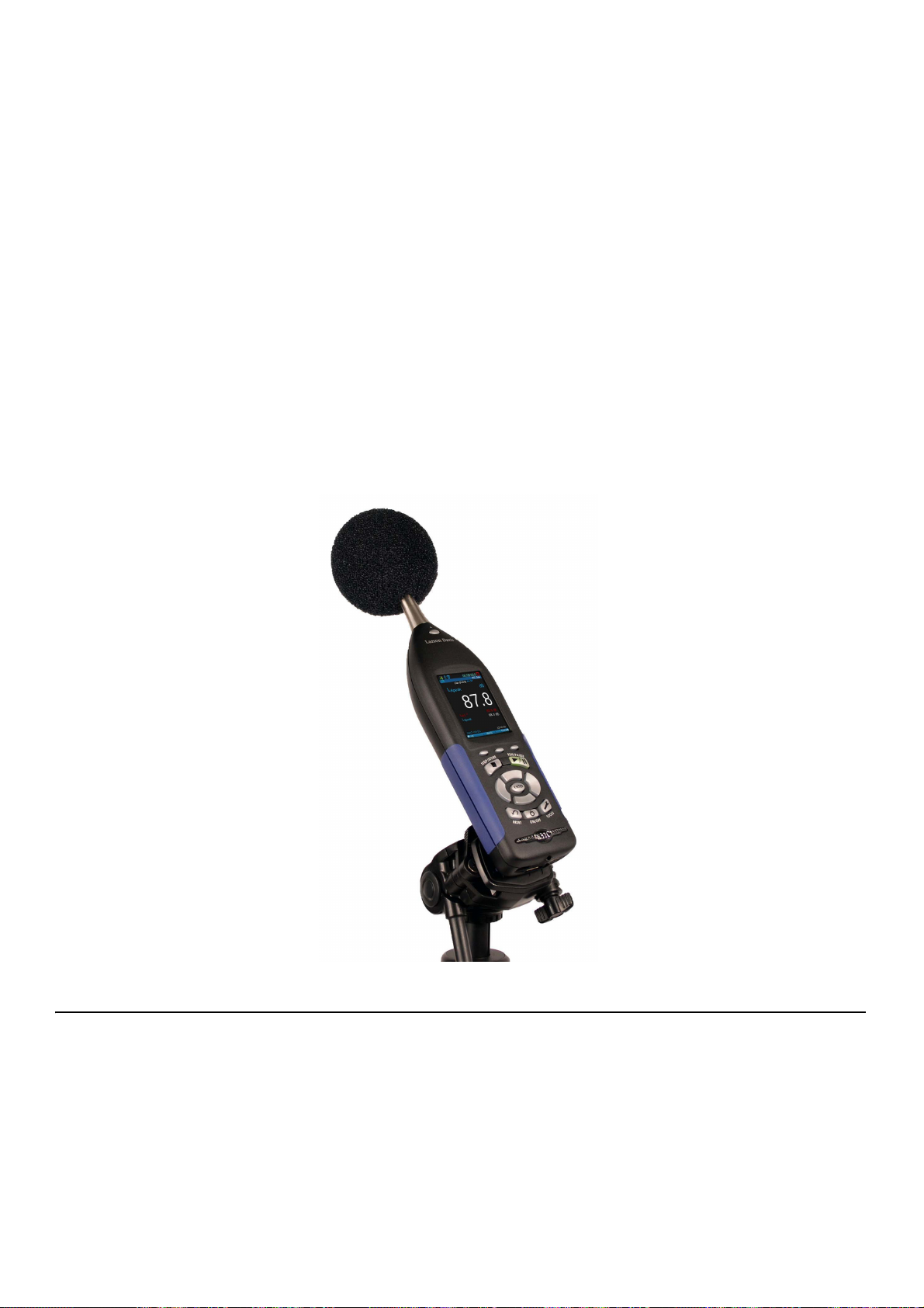
Microphone Extension Cable
TAKE NOTE Always position
the preamplifier/microphone in
a way to minimize the effect of
reflections on the sound field
near the microphone.
Windscreen
FIGURE 7-2 Windscreen
A shielded microphone extension cable may be placed between the meter
and the preamplifier/microphone if needed for the measurement position.
No correction is necessary when using Larson Davis Model EXCXXX
microphone extension cables in combined lengths up to 200 feet. XXX is
the length in feet (XXX = 010, 020, 025, 035, 050, 060, 100 and 200)
available.
Wind blowing across the microphone generates pressure fluctuations on
the microphone diaphragm which can produce errors in the measurement.
As a result, when performing measurements in the presence of low level
airflows, it is recommended that a windscreen be placed over the
microphone. Larson Davis provides the WS001 windscreen, a 3 1/2”
diameter ball made of open cell foam which can be placed over the
microphone and preamplifier.
7.2.2 Area Sound Field Check
Starting a measurement during a dramatic sound change can affect your
data in an unwanted way. Before starting any measurement, check the
area sound field by navigating to Live on the meter and ensuring your
measurement is ready to begin.
While every task is unique, the following scenario is standard for a basic
measurement:
SoundAdvisor Model 831C Before You Start 7-3
Page 78

• The live sound is steady and within range. See “SLM Performance” on page A-2 and “Low Level Sound Fields” on page 7-8.
• The time reads 00:00:00.0 on both the Live and Overall displays.
(Otherwise the previous measurement was not stored or reset.)
• The measurement status icon is set to Stop.
For more information, see “SLM Page” on page 4-2
FIGURE 7-3 Standard Area Sound Field Before Measurement
7.3 Performing the Measurement
LEARN MORE To learn more
about the displays and icons,
see “Displays and Icons” on
page 2-6
Keypad LED Indicators
Table 7.1 Measurement State LED Indicators
Measurement State Red LED 7 Green LED 9
Stopped Blinking *---*--- Off
Paused Flashing *-*- Flashing -*-*
Running Off Winking **--**--
At this point you are ready to begin a measurement.
Navigate to Overall on the SoundAdvisor and press RUN 9.
When performing a measurement, the state of the SoundAdvisor is
indicated in several ways: measurement state icon, Overall display
animation, and the red and green illumination of the STOP/STORE and
RUN/PAUSE keys.
SoundAdvisor Model 831C Performing the Measurement 7-4
Page 79

Table 7.1 (Continued)Measurement State LED Indicators
Measurement State Red LED 7 Green LED 9
Waiting for valid
data to begin running
The Measurement Range
Delayed
wink
The measurement ranges over which the SoundAdvisor meets the
standards depends upon the selected frequency weighting. Measurements
which include levels outside this range should not be considered accurate.
An overload indication will appear when levels are above the range.
However, it isn’t recommended to rely on measurements where the levels
are below the lower limit of the specified range.
----* Off
Overload
As part of the calibration procedure, the overload level (dB Peak) and the
under range sound pressure levels for A, C and Z weighting are
determined for the instrument setup and microphone/preamplifier
combination being used. When a signal from the preamplifier exceeds the
calibrated input range of the SoundAdvisor, an overload condition exists.
To learn more see “Input Overload Icon” on page 2-10
Under Range
When the signal from the preamplifier drops to the point where the noise
level of the instrument and the preamplifier influence the measurement,
an under range condition exists. To learn more, see “Under Range Icon”
on page 2-10
7.3.1 Pausing the Measurement
TAKE NOTE A measurement
may be paused and resumed
multiple times.
Erase Previous 5-10 Seconds of Measurement
At any time the measurement of overall data can be temporarily paused.
During a pause, the run clock will not stop and instantaneous data will
continue to be displayed on the Live display.
After a pause, press the 9 RUN/PAUSE key to resume the
measurement. The overall data will not be affected by any acoustic events
occurring during the time period that the SoundAdvisor was paused.
The SoundAdvisor has a back-erase feature that allows for a quick erase
of the last 5 to 10 seconds of measured data. This feature is used to erase
sounds that are recorded, but not wanted in the overall measurement.
Back Erase Disabled
The back erase feature is unavailable when any of the following have
been enabled in the Active setup:
TAKE NOTE Pressing any other
key besides the back-erase
option will end the back-erase
state.
• Measurement History
• Event History
• Spectral Ln
SoundAdvisor Model 831C Performing the Measurement 7-5
Page 80
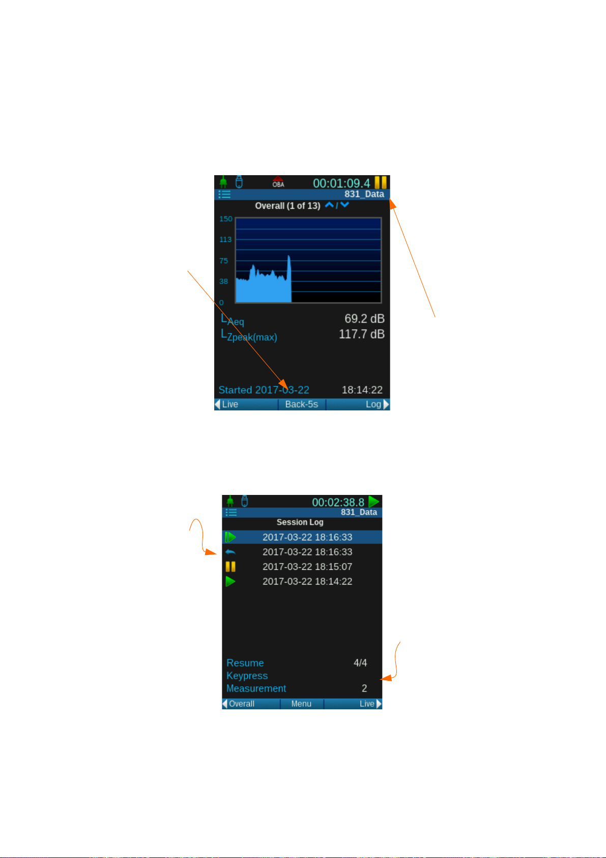
FIGURE 7-4 Back Erase
The Back Erase
feature is located
where Menu
typically is.
After the first erase,
you can erase an
additional 5 seconds
(not an additional 10).
Undo appears as an
option after a ten
second erase.
To close Back Erase,
start a run again, press
the Stop button.
Back erase icon will
appear when a part
of the measurement
was erased during a
pause.
The amount of time
that was erased will
be shown in the
information box.
• Event Sound Recording
Back Erase
The back erase is visible when the measurement is paused, and only after
the measurement has run more than 5 seconds since the last run or
resume.
Session Log
The session log will have an icon to indicate data had been erased.
FIGURE 7-5 Back Erase in the Session Log
SoundAdvisor Model 831C Performing the Measurement 7-6
Time History Records
The time history starts from the time the data was restored. The erased
data will be marked as Back Erase as the record type.
Page 81

FIGURE 7-6 Measurement Data for Back Erase
7.3.2 Resetting a Measurement
CAUTION The measurement
data will be lost if not saved.
Additionally, saved data will
not be lost during a reset.
CAUTION If a reset happens
while a measurement is running or paused, the SoundAdvisor will automatically stop
the measurement for the reset,
A measurement often needs to be reset when a radical noise event takes
place that is unnecessarily recorded in your data. For example, an aircraft
passing overhead when attempting to measure the background noise in a
normally quiet area.
To reset a measurement in progress, stop the measurement then press the
1 (RESET) key. This will erase all data previously measured and reset
the run time clock to zero. A reset will not reset stored data files, only the
current run. A reset can be initiated when the SoundAdvisor is running,
paused, or stopped.
and data will be removed.
7.3.3 Stopping the Measurement
The SoundAdvisor can be stopped during a run or a pause, and will stop
the run clock. Resuming a run will continue the overall measurement
which has been stopped. The run clock will also begin again from the time
indicated when the stop occurred.
7.4 Storing the Measurement
TAKE NOTE A measurement
To store a measurement, follow these steps:
can only be stored when the
SoundAdvisor is stopped.
TAKE NOTE You cannot save a
file with the same name as a
Step 1 Press the Stop 7 button to stop the measurement.
Step 2 Press the Store 7 button (unless your preferences are set to
Auto-store, then the first Stop will store or prompt to store).
currently saved data file. If you
want the new data file to
replace the old data file, you
will need to rename or delete
the old file first. See “Mea-
Step 3 You will be prompted to save the file. You can change the
name of the data file by highlighting the name and pressing
Enter 5, and an editor will appear. When finished, select
Ye s to save.
surement Data Files” on
page 8-1
SoundAdvisor Model 831C Storing the Measurement 7-7
Page 82

7.5 Low Level Sound Fields
()
Lcorr Log10 10 10
Lmeas Linh()/10()/10
As long as the sound level being measured is within the measurement
range shown in “SLM Performance” on page A-2, inherent (selfgenerated) noise and linearity problems can be ignored. It is possible to
manually correct the measured RMS sound pressure levels for the typical
inherent noise levels (see the noise floor specifications in “SLM
Performance” on page A-2) as long as the difference between the
measured sound level and the inherent noise level is greater than 3 dB.
This is done by subtracting the inherent sound level from the total sound
level using the following formula:
where
Lcorr = corrected sound level
Lmeas = measured sound level
Linh = inherent noise level
SoundAdvisor Model 831C Low Level Sound Fields 7-8
Page 83

Module
8.1 Overview ............................................................................................................... 8-1
8.2 Data Storage Preferences .....................................................................................8-1
8.3 Data File Manager ................................................................................................. 8-2
8.3.1 View Measurement Data File ................................................................... 8-3
8.3.2 Load Settings ........................................................................................... 8-3
8.3.3 Create Average ........................................................................................ 8-4
8.4 USB Drive Storage ................................................................................................ 8-4
8.4.1 Save File to USB Drive ............................................................................ 8-6
8.5 File Naming System .............................................................................................. 8-6
8.6 Out Of Memory ......................................................................................................8-7
8.7 Access Limited ......................................................................................................8-7
8 Measurement Data Files
8.1 Overview
TAKE NOTE A basic measure-
ment records about 42.5 KB.
FIGURE 8-1 Data File Manager
For every measurement saved, a new data file is created on the
SoundAdvisor. The SoundAdvisor saves up to 1.8 GB of data in internal
memory. Additionally, an external USB drive can be used to store more
data.
8.2 Data Storage Preferences
To indicate where measurement files are stored by default, navigate Tools
System PropertiesPreferences.
SoundAdvisor Model 831C Overview 8-1
Page 84
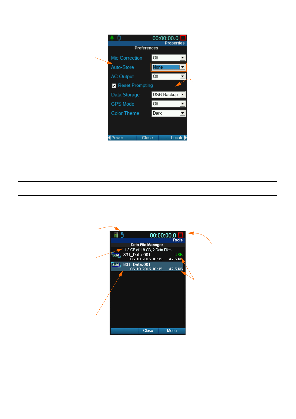
FIGURE 8-2 Preferences Page
Every stop will store a
measurement if Autostore is set. You can be
prompted to confirm the
store, or it can be
automatic.
Your measurement can store
on the internal memory, USB
drive, or both.
A USB drive is inserted,
so the USB icon is
displayed.
The current measurement
can be running, paused, or
stopped while viewing data
files.
This is the available
storage, unless the USB
is connected and set for
store-only, then it will
be the USB storage
space.
The data file name is the
name indicated in the
setup and used for that
measurement.
The top file is saved on the
USB drive, and the one
below is saved on the
meter’s internal memory in
this example.
LEARN MORE To save a file on
the USB drive see “Save File
to USB Drive” on page 8-6.
8.3 Data File Manager
Data File Manager is a directory of all saved measurement data files.
FIGURE 8-3 Data File Manager
SoundAdvisor Model 831C Data File Manager 8-2
Page 85

FIGURE 8-4 Data File Manager Menu
Highlight a data
file before
selecting Menu.
The options in
the menu will
affect the
highlighted data
file.
You can Rename,
Delete, and Delete All
Internal Files.
Refresh List and
navigation commands
are on the menu as well.
8.3.1 View Measurement Data File
FIGURE 8-5 Data File Icon
8.3.2 Load Settings
TAKE NOTE Ensure that you
save your current settings
before loading. You will lose
any settings you had on the
Active setup. On how to do
this, see “User Defined Setup”
on page 6-9.
Navigate Menu Data File Manager Highlight desired data file
Menu View.
A read-only display of the Overall and Session Log tabs will show the
data from that measurement. To indicate that you are seeing a
measurement data file and not the live data, the data file icon will appear
next to the data file name.
A saved data file’s settings can be loaded to the Active setup to be used
for a measurement.
Stop any measurement currently running or paused before loading the
new settings. Navigate to Menu Data File Manager Highlight
desired data file Menu Load Settings.
There is no indication that the settings were loaded, so it is encouraged to
review the Active setup after loading. Close the Data File Manager,
navigate Menu Setup Manager then cycle through the Active
settings.
SoundAdvisor Model 831C Data File Manager 8-3
Page 86

8.3.3 Create Average
Create Average takes a saved data file and adds its average as an instance
to the unsaved Overall measurement.
• Any unsaved measurement will be overwritten with the new
average instance.
• You can add multiple files to the average and each appears as a
new instance in the overall measurement. However, each file can
only be added once.
• A measurement can run after the averages are loaded, though not
recommended for averaging purposes.
• After data files are averaged, you can save the new data as a single
file.
Follow these steps to create an average of your data file(s):
Step 1 Navigate to Menu Data File Manager.
Step 2 Highlight desired data file.
8.4 USB Drive Storage
Step 3 Select Menu.
Step 4 Select Create Average.
Step 5 Highlight a different data file.
Step 6 Select Menu.
Step 7 Select Add to Average.
Step 8 Repeat Steps 4-6 until all data files you want to average have
been added.
Step 9 After all the data files are averaged, close the Data File
Manager and navigate to the Overall display to view data.
Step 10 Save the new data file by pressing Store 7.
The SoundAdvisor has a built in USB port where an external memory
drive can be inserted, and where measurement data files can be saved.
When the USB drive is inserted, the USB Drive Icon will appear next to
the battery state icon on the meter.
FIGURE 8-6 USB Drive Icon
SoundAdvisor Model 831C USB Drive Storage 8-4
Page 87

When USB is inserted, the Data File Manager shows a list of all the data
files stored on this USB device. The files saved to the USB device are
denoted by the green text USB over the file size.
If the “Data Storage Preferences” is set to USB only, this icon will appear:
FIGURE 8-7 USB Only Storage Icon
The Menu has additional items when a USB drive is detected.
FIGURE 8-8 Data File Manager USB Menu
If your settings indicate that the measurements be stored on a USB drive
and no USB drive is inserted, this icon will appear. Files will save to the
meter until you insert a USB drive.
If the USB drive is removed during a measurement, the icon below will
appear and the measurement will end and data with that measurement will
not be visible on the meter. When the USB drive is reinserted you will be
notified that there is unsaved data and prompted to save or delete the
measurement data. You cannot continue with that same measurement.
FIGURE 8-9 USB Not Inserted Icon
In the scenario where USB is set to primary, but was inserted during a
measurement run-- the files will save internally until the next reset. This is
indicated by the following icon.
FIGURE 8-10 USB Inserted During Run
SoundAdvisor Model 831C USB Drive Storage 8-5
Page 88

8.4.1 Save File to USB Drive
Follow these steps to save a data file to a USB drive manually:
Step 1 Insert USB drive to the SoundAdvisor. Wait for the USB
icon to appear on the top left of the screen (about ten seconds).
Step 2 Navigate to Menu Data File Manager.
Step 3 Highlight desired data file.
Step 4 Select Menu.
Step 5 Select desired action:
• Copy File to USB
•The data file will be copied onto the USB drive. The
original file will remain saved on the SoundAdvisor.
• Move File to USB
•The original data file will move onto the USB drive,
and no longer in internal memory.
Step 6 Check Data File Manager to confirm desired action was
8.5 File Naming System
Measurement data files saved cannot be named the same, so there are two
ways that files names are automatically generated on the SoundAdvisor.
These naming conventions are a product of the run mode indicated in a
setup. See “Control” on page 6-6.
• Copy All Internal to USB
•All data files on the SoundAdvisor will be copied onto
USB drive. The original data files will remain saved
in internal memory.
• Move All Internal to USB
•All original data files on the SoundAdvisor will be
moved onto the USB drive, and no longer be saved
in internal memory.
completed.
The following table explains the data naming conventions used on the
SoundAdvisor:
SoundAdvisor Model 831C File Naming System 8-6
Page 89

Table 8.1 Data File Naming Systems
Run Mode File Naming Convention Example Additional Information
Manual Stop “Default Data File”.NNN 831_Data.001 The “Default Data File” can be changed on
the General setup page. Once the numbers
reach 999, the next data file will be .001.
Continuous YYMMDDHex.LD0 1610110A.LD0 In this mode, the name will be a time stamp
with the year, month, and day followed by a
hex number that increments.
8.6 Out Of Memory
In order to ensure that all measured data can be stored, the SoundAdvisor
will stop automatically when the amount of available memory drops to 10
MB. If the unsaved data is less than 800 kB, you can save it after the
forced stop.
Download all data to an external drive or PC, or delete, before performing
another measurement.
8.7 Access Limited
The SoundAdvisor can be accessed by several different sources at once,
however the Data File Manager can only be access by one user, one
source at any given time. If another user is in the Data File Manager and a
second attempts to open it, they will be prompted to end the first user’s
session to start their own.
SoundAdvisor Model 831C Out Of Memory 8-7
Page 90

Module 9 System Properties
9.1 Overview ............................................................................................................... 9-1
9.2 Device ...................................................................................................................9-2
9.3 Time ......................................................................................................................9-2
9.4 NTP .......................................................................................................................9-3
9.5 Power ....................................................................................................................9-3
9.6 Preferences ........................................................................................................... 9-6
9.7 Localization ...........................................................................................................9-9
9.8 Displays ............................................................................................................... 9-10
9.9 Options ................................................................................................................9-11
9.10 Network ...............................................................................................................9-11
9.11 Email ...................................................................................................................9-12
9.12 Other ...................................................................................................................9-13
9.13 Set Reference Spectra ........................................................................................ 9-14
9.1 Overview
System Properties are control functions of the SoundAdvisor and not
related to sound measurement or calculations, but rather instrument
properties and instrument settings.
SoundAdvisor Model 831C Overview 9-1
Page 91

9.2 Device
The time will not update if
the meter is running or
paused. Stop the
measurement before setting
time, otherwise the time
will wait to update until the
next Stop.
Set your time zone first
then select Save.
If you have NTP time it is
not necessary to set this. If
you want to manually set
time and override any
syncing, adjust this and
select Set Time.
Close to save all
changes.
Enter 30 characters per field of device information that will appear on the
About page under the Tools menu. See “About System” on page 10-1.
FIGURE 9-1 Instrument Identification
9.3 Time
There are several ways that you can update the time on the meter: GPS,
NTP servers, PC clock, or manually set the time. This page is designed for
the manual set, but is still automatic for daylight savings, just as long as
your timezone is set accurately.
FIGURE 9-2 Set Date/Time & Timezone
SoundAdvisor Model 831C Device 9-2
Page 92

TAKE NOTE
SoundAdvisor with a PC time,
use G4 LD Utility under the
Maintenance tab of the Meter
Manager. For more
information refer to the G4 LD
Utility Reference Manual.
To sync the
9.4 NTP
FIGURE 9-3 NTP Servers
The SoundAdvisor communicates with NTP servers to sync the internal
clock with the most accurate time. This requires a valid Internet
connection either through Ethernet, wireless modem, or WiFi.
FIGURE 9-4 NTP Icon
9.5 Power
9.5.1 Battery Type
When your time has successfully been synced with NTP servers, the NTP
icon will appear next to your time. See Figure 9-4 NTP Icon.
If the time is synced with NTP and Internet connection is then loss, the
SoundAdvisor will attempt to reconnect the servers for up to 2 1/2 hours.
During this time the icon will remain. If the servers cannot be reached
after that time, the icon will disappear.
The SoundAdvisor can be powered by Nickel-Metal Hydride, Alkaline,
or Lithium AA batteries. It should always be defined on this System
Properties Power page to prevent damage to meter. This information is
also used for the calculation of the battery life.
SoundAdvisor Model 831C NTP 9-3
Page 93

FIGURE 9-5 Battery Type
LEARN MORE To learn more,
see “Battery Power” on
page 3-4.
9.5.2 Charge
9.5.3 Auto-Off
CAUTION Do not mix Alkaline and NiMH batteries.
CAUTION Do not mix batteries from different manufacturers
CAUTION Replace all four batteries when installing fresh cells
CAUTION The correct battery type must be specified, based on the battery
type installed. Serious damage, injury, or fire can occur when the battery
type is set to NiMH but Alkaline or Lithium batteries are installed
because the internal charger will be enabled.
The SoundAdvisor can charge Nickel Metal Hydride batteries that are
installed properly. Charge is an On and Off feature that is only available
when you have Nickel-Metal Hydride batteries.
Auto-Off time is the duration of time the instrument will stay on when
there is no activity. Any of these actions will keep the meter on and reset
the Auto-Off time:
FIGURE 9-6 Auto-Off
9.5.4 Analog Power-Save
FIGURE 9-7 Power Save Icon
• Button presses
• Running a measurement
• USB communications
Pressing the 0 (ON / OFF) key will return the instrument and the display
to the state it was in when the Auto-Off time expired.
SoundAdvisor Model 831C Power 9-4
Page 94

FIGURE 9-8 Analog Power-Save
In the power save mode, battery power will significantly reduce by
shutting down the analog circuitry and the signal processing
activities.This feature is designed to shut down all data collecting
processing to save on battery.
The analog power-save time is the duration of time the instrument will
stay fully powered after a measurement has stopped. The analog circuitry,
including power to the preamplifier will shut down when the instrument
has been stopped for the time set. Starting a measurement or performing a
reset will restore power to the analog circuitry and the instrument can run
the measurement after a ten second delay.
Performing a calibration will also restart the analog power-save time.
9.5.5 Backlights On
FIGURE 9-9 Backlights On
9.5.6 Keypad Backlight
LCD Brightness
Backlights-On is the duration the SoundAdvisor display will be back lit
after the last key press. Selecting Always on will increase power
consumption.
By toggling keypad backlights to Off, the blue LED under all the keys
will turn off. The Red LED on STOP/STORE, and the green LEDs under
the RUN/PAUSE and ON/OFF will remain on.
TAKE NOTE Using the
backlight on bright setting will
significantly increase power
consumption and decrease
battery life.
SoundAdvisor Model 831C Power 9-5
You can set the intensity of the backlight of the LCD screen to 100%,
80%, 60%, 40%, or 20%.
In the event that the battery life is below 10%, the SoundAdvisor will
override the user setting and downgrade to 50% LCD Brightness, unless
the user setting is below 50% brightness, then it will remain the same.
Page 95

FIGURE 9-10 LCD Brightness
9.5.7 External Shutoff Voltage
To avoid damaging the internal batteries when the voltage of an external
battery drops too low, you can set an external shutoff voltage. The
SoundAdvisor will shut off automatically when the external voltage drops
below this level.
The default level is 10.8 volts, but you can enter a value in the range 10 to
25 volts if your battery usage is other than standard.
9.6 Preferences
9.6.1 Microphone Correction
When using a free-field microphone, a correction can be applied to
provide a random incidence response or, when using a random incidence
microphone, a correction can be applied to provide a free-field response.
FIGURE 9-11 Mic Correction
9.6.2 Auto-Store
The Auto-store feature applies to all measurements taken on the device.
None
All storage must be done manually, unless in the continuous daily autostore mode indicated in a setup.
TAKE NOTE When a store
occurs, whether prompt or
auto, the measurement is reset
at the time of the store.
SoundAdvisor Model 831C Preferences 9-6
Prompt
When the 7 Stop button is pressed, or a stop occurs, you will be
prompted to save the measurement data file.
Page 96

Store
A measurement is automatically stored when a measurement is stopped.
Table 9.1 Run Mode Behavior for Auto-store
Run Mode Type of Stop Auto-Store Preference
Prompt Store
Timed Stop
Stop When Stable
Single Block Timer
Daily Timer
9.6.3 AC Output
LEARN MORE Refer to “Soun-
dAdvisor Model 831C Instrument Platform” on page A-1.
Timer-activated final
stop
Manually activated No action performed No action performed
Timer-activated stop Prompts when stable File automatically stored
Manually activated Prompts when stopped File automatically stored
Timer-activated stop Prompts when timer
Manually activated Prompts when stopped File automatically stored
Timer-activated stop No prompt; File automat-
Manually activated No action performed No action performed
Prompts when timer is
complete
completes
ically stored
File automatically stored
File automatically stored
File automatically stored
The AC output is a full dynamic range AC/DC output. It does not drive a
headset or headphones.
If the signal is set to Off, then the AC/DC output is not powered.
FIGURE 9-12 SoundAdvisor AC/DC Output Jack
SoundAdvisor Model 831C Preferences 9-7
Page 97

9.6.4 Reset Prompting
9.6.5 Data Storage
If a measurement is made that is unwanted, you can press the 1 Reset
button to clear the unsaved data. By checking the Reset Prompt box, the
meter will give you a dialogue box to confirm a reset before clearing the
data.
This feature indicates where your data file will store:
TAKE NOTE If a USB drive is
not inserted, data files will
save onto the SoundAdvisor
memory, regardless of
indicated preference.
9.6.6 GPS Mode
9.6.7 Color Theme
Internal
Data files saved manually and through auto-store will save onto the
SoundAdvisor 2 GB memory (1.8 GB usable).
USB
Data files saved manually and through auto-store will save onto the
inserted USB drive.
USB Backup
Data files will save on both the SoundAdvisor internal memory and
inserted USB drive.
GPS mode will need to be On if a GPS device is inserted in the Aux drive,
and you wish to use it.
The SoundAdvisor LCD screen has six options for color themes: three
light and three dark. The light screens are encouraged to be used when
sunlight or outdoor settings are mostly present when operating the meter,
and the dark themes are better for indoor or low light use.
SoundAdvisor Model 831C Preferences 9-8
Page 98

FIGURE 9-13 Color Themes
9.7 Localization
Language
The SoundAdvisor has a built in language translation feature, where you
can set your language preference.
The following languages are available:
• English
•Cestina
• Français
• Deutsch
•Italiano
•Norsk
• Português (PT)
• Português (BR)
•Español
• Svenska
• Türkçe
SoundAdvisor Model 831C Localization 9-9
Page 99

FIGURE 9-14 Language Selection
Decimal Symbol
Depending on your preference, the decimal symbol on the units of
measurement can be a period or a comma. Select the radio button of the
desired symbol, and save to make changes.
Date Format
The SoundAdvisor has two date formats day-month-year and year-monthday. Both options are in two number digit displays. For example: 201702-14. Select the radio button of the desired format, and save to make
changes.
9.8 Displays
Units
The default units for the SoundAdvisor is SI (International System of
Units), however you can change this to English units. Select the radio
button of the desired unit, and save to make changes.
When you power your meter on, the first display page defaults to the
profile page of the Live display. This can be changed on the Displays
page.
Start
Start refers to the display that is shown first when you boot up the
SoundAdvisor. You can choose any of the main displays available to you.
Select your option from the drop down box, save, and close. The next
time your meter powers on, you will see your start display.
Tabs & Pag es
Each Tab chosen will show a new list in the Pages section. You can check
or uncheck pages depending on what you want shown on the meter. This
feature will hide unwanted page displays, not delete them.
SoundAdvisor Model 831C Displays 9-10
Page 100

FIGURE 9-15 Display Options
9.9 Options
TAKE NOTE Default options
will not appear in the list as
they cannot be disabled.
FIGURE 9-16 Options Enable/Disable
You can enable or disable options installed on the SoundAdvisor.
Disabling an option does not delete the option, and it can be enabled at
anytime.
A reboot is required after any changes are made.
9.10 Network
See “Communications & WiFi” on page 13-1.
SoundAdvisor Model 831C Options 9-11
 Loading...