

Page 1

Model 831
Sound Level Meter
Manual
Page 2

Larson Davis
Model 831 Manual
I831.01 Rev O Manual
Page 3

Copyright
Copyright 2016, by PCB Piezotronics, Inc. This manual is copyrighted, with all rights reserved. The
manual may not be copied in whole or in part for any use without prior written consent of PCB
Piezotronics, Inc.
Disclaimer
The following paragraph does not apply in any state or country where such statements are not
agreeable with local law:
Even though PCB Piezotronics, Inc. has reviewed its documentation, PCB Piezotronics Inc. makes no
warranty or representation, either expressed or implied, with respect to this instrument and
documentation, its quality, performance, merchantability, or fitness for a particular purpose. This
documentation is subject to change without notice, and should not be construed as a commitment or
representation by PCB Piezotronics, Inc.
This publication may contain inaccuracies or typographical errors. PCB Piezotronics, Inc. will
periodically update the material for inclusion in new editions. Changes and improvements to the
information described in this manual may be made at any time.
Record of Serial Number and Purchase Date
Model 831 Serial Number: ___________
Preamplifier Model: _________ Serial Number: ___________
Microphone Model: _________ Serial Number: ___________
Recycling
PCB Piezotronics, Inc. is an environmentally friendly organization and encourages our customers to
be environmentally conscious. When this product reaches its end of life, please recycle the product
through a local recycling center or return the product to:
PCB Piezotronics, Inc.
Attn: Recycling Coordinator
1681 West 820 North
Provo, Utah, USA 84601-1341
where it will be accepted for disposal
Warranty
For warranty information, refer to our Terms and Conditions of Sale on our website,
www.larsondavis.com/TermsConditions.aspx.
Page 4

Table of Contents
Chapter 1 831 Features 1-1
Hardware Features ................................. .................................. ............................. 1-1
Basic Measurements ............................................................................................. 1-2
Basic Operation ..................................................................................................... 1-2
Available Options ............................................. .................................................... 1-3
Standard Accessories ............................................................................................ 1-4
Optional Accessories ............................................................................................. 1-5
Chapter 2 First Use 2-1
Unpacking and Inspection ..................................................................................... 2-1
Connecting the Microphone and Preamplifier ...................................................... 2-2
Connecting the Preamplifier ................................................................................. 2-3
Disconnecting the Preamplifier ........................................................... .................. 2-4
Powering the Model 831 ....................................................................................... 2-4
Chapter 3 Overview 3-1
831 Components ................................................................................................... 3-1
Summary of Displays and Icons ........................................................................... 3-7
Navigating and Selecting ....................................................................................3-12
Basic Run Functions ...........................................................................................3-12
Tab and Setting Displays .................................................................................... 3-13
Parameter Selection ............................................................................................. 3-20
Chapter 4 Basic Measurement Setup 4-1
Settings Screen ...................................................................................................... 4-1
Setup Tabs .................................................................................................... ......... 4-2
Exiting Settings Screen ....................................................................................... 4-15
Setup Manager ................................. .................................. .................................4-16
Chapter 5 Data Display 5-1
Data Labels ........................................................................... ... ............................. 5-1
Tabbed Structure ............................................................................................... .... 5-1
Live Tab ...................................... .................................. ........................................ 5-2
Overall Tab ............................................... .......................................................... 5-12
C-A and Impulsivity ............................................................................................ 5-23
Session Log Tab ..................................................................................................5-25
Adjust Graph Scale ............................................................................................. 5-29
I831.01 Rev O Manual
Page 5

View Spectrum Normalized ................................................................................5-30
Any Level Display ...............................................................................................5-41
Chapter 6 Run Control 6-1
Run Control Setup .................................................................................................6-1
Run Mode with Measurement History ..................................................................6-3
Run Modes Without Measurement History ...........................................................6-4
Chapter 7 Making a Measurement 7-1
Configuration of the System ..................................................................................7-1
Switching On the Model 831 ................................................................................. 7-1
Model 831 Setup ....................................................................................................7-3
Calibrating the Model 831 .....................................................................................7-3
Positioning the Model 831 .................................................................... .................7-3
Performing the Measurement ................................................................................7-5
Storing the Measurement .....................................................................................7-15
Recovery After Improper Shutdown ...................................................................7-17
Chapter 8 Calibration 8-1
Calibration Overview .............................................................................................8-1
Control Panel - Calibrate .......................................................................................8-2
Acoustic Calibration ..............................................................................................8-5
Sensitivity Tab .....................................................................................................8-13
Calibration Without Preamplifier ........................................................................8-15
Certification ......................................................................................................... 8-16
E.A. Check .......................................................... .................................. ...............8-18
E.A. History ................................................... ......................................................8-20
Chapter 9 Industrial Hygiene 9-1
Measurement Setup ...............................................................................................9-1
Data Display ..........................................................................................................9-5
Chapter 10 Voice Recording 10-1
Control Panel - Voice Recording .........................................................................10-1
Voice Recorder ....................................................................................................10-2
Chapter 11 Time History 11-1
Metrics Logged ....................................................................................................11-1
Time History Setup ..............................................................................................11-4
Time History Display ..........................................................................................11-9
Page 6

Locate Record Number ..................................................................................... 11-16
Link to Measurement History Display .............................................................. 11-17
Markers ............................................................................................................. 11-18
Chapter 12 Measurement History 12-1
Run Control with Measurement History ............................................................. 12-1
Continuous and Timer Modes ............................................................................. 12-2
Timed Stop Mode ................................................................................................ 12-3
Manual and Stop When Stable Modes ................................................................ 12-5
Display of Measurement History Data ................................................................12-5
Storing a Measurement History ........................................................................12-11
Link to Time History ......................................................................................... 12-11
Chapter 13 Event History 13-1
Level Based Events ............................................................................................. 13-1
Event History Setup ....................... .....................................................................13-2
Trigger Method ................................................................................................... 13-3
Event Time History Setup ................................................................................. 13-10
Event History Display .......................................................................................13-12
Link to Time History and Measurement History .............................................. 13-22
Chapter 14 FFT and Tonality 14-1
Accessing FFT Mode .......................................................................................... 14-1
Configuring a Measurement ............................................ ... .................................14-3
Viewing and Analyzing Results ........................................................................ 14-10
Storing Data ................................ .................................. ....................................14-21
Viewing Stored Data ......................................................................................... 14-21
Return to Sound Level Meter Mode ......................................................... ........ 14-22
Chapter 15 RT-60 15-1
Accessing RT-60 Mode ............................................. ......................................... 15-1
Making a Measurement .......................................................................................15-3
Viewing and Analyzing Results .......................................................................... 15-8
Manually Controlling the Internal Noise Source .............................................. 15-16
Customizing Measurements ............................................ ..................................15-20
Storing Data ................................ .................................. ....................................15-26
Viewing Stored Data ......................................................................................... 15-26
Quality Indicators .............................................................................................. 15-27
Accuracy Grade ................................................................................................. 15-28
Return to Sound Level Meter Mode ......................................................... ........ 15-29
I831.01 Rev O Manual
Page 7

Chapter 16 Sound Recording 16-1
Sound Recording Types ....................................................................................... 1 6-1
Sound Recording Setup .......................................................................................16-2
Manual Sound Recording ....................................................................................16-7
Marker Initiated Recording .................................... ..............................................16-9
Event Sound Recording .....................................................................................16-14
Measurement History Sound Recording ............................................................16-18
Combined Sound Recordings ............................................................................16-19
Sound Recording Playback ................................................................................16-20
Chapter 17 Data Explorer 17-1
Control Panel - Data Explorer .............................................................................17-1
Data Explorer .......................................................................................................17-2
Chapter 18 System Properties 18-1
Control Panel - System Properties .......................................................................18-1
Device ..................................................................................................................18-2
Time .....................................................................................................................18-3
Power ...................................................................................................................18-5
Preferences ......................................................................................................... 18-10
Localization .......................................................................................................18-20
Displays .............................................................................................................18-23
Options ...............................................................................................................18-29
Logic I/O ............................................................................................................18-31
Chapter 19 Non-Acoustical Inputs 19-1
831-INT ...............................................................................................................19-1
Weather Measurement Using 831-INT ...............................................................19-2
Location Measurement Using 831-INT .............................................................19-10
Chapter 20 Communication 20-1
Control Panel - Communication ..........................................................................20-1
Modem Tab ..........................................................................................................20-3
Wireless Tab ........................................................................................................20-6
RS-232 Tab ...................................................................................................... ....20-8
SMS Out ..................................................... .......................................................20-12
Network Tab ......................................................................................................20-13
Status Tab ..........................................................................................................20-15
Troubleshooting .................................................................................................20-20
Page 8

Chapter 21 Lock/Unlock the Model 831 21-1
Control Panel - Lock ...........................................................................................21-1
Fully Locked ....................................................................................................... 21-5
Locked With Auto-Store ............................................... ...................................... 21-6
Locked With Manual-Store ................................................................................. 21-7
Calibration When The Model 831 Is Locked ...................................................... 21-8
Chapter 22 About 22-1
Control Panel - About ......................................................................................... 22-1
About ................................................................................................................... 22-1
Standards ............................................................................................................. 22-2
Options ................................................................................................................ 22-3
User ..................................................................................................................... 22-4
Chapter 23 System Utilities 23-1
Control Panel - System Utilities ..........................................................................23-1
File System .......................................................................................................... 23-2
Chapter 24 Parameters Measured 24-1
Basic Sound Level Measurements ...................................................................... 24-1
Sound Exposure Metrics Measured .................................................................... 24-3
Statistical Metrics Measured ............................................................................... 24-4
Exceedance Counters .......................................................................................... 24-6
Miscellaneous Parameters ................................. .................................................. 24-6
Time History (831-LOG Required) .................................................................... 24-6
Measurement History (831-ELA Required) ....................................................... 24-6
Event History (831-ELA Required) .................................................................... 24-6
Chapter 25 Memory Utilization 25-1
Out Of Memory Stop .......................................................................................... 25-1
Overall Data ..................................... .................................. .................................25-1
Session Log ......................................................................................................... 25-1
Measurement History .......................................................................................... 25-2
Time History ....................................................................................................... 25-2
Events .................................................................................................................. 25-2
Voice Messages ...................................................................................................25-3
Sound Recording .................................................................................................25-3
Bad Flash Blocks ........................................................................... ..................... 25-4
I831.01 Rev O Manual
Page 9

Chapter 26 Upgrade Firmware and Options 26-1
SLM Utility-G3 ...................................................................................................26-1
Upgrading Model 831 Firmware .........................................................................26-2
Upgrading Options ..............................................................................................2 6-7
Appendix A Technical Specifications A-1
Standards Met by Model 831 ............................................... .................................A-1
Model 831 Specifications .....................................................................................A-2
CE Information ...................................................................................................A-20
1/1 and 1/3 Octave Filters ...................................................................................A-21
Position of Instrument and Operator ...................................................................A-30
Frequency Response ...........................................................................................A-32
Vibration Sensitivity ...........................................................................................A-62
Appendix B Measuring to IEC61672-1 B-1
Sections 5, 6, 7 and 9 (except 9.3) ........................................................................B-1
Appendix C Integrated Level Calculations C-1
Basic Integrated Level Calculations .....................................................................C-1
Community Noise Descriptors .................................... .........................................C-9
Appendix D Glossary D-1
Page 10

CHAPTER
1
Hardware Features
831 Features
Welcome to the Larson Davis Model 831. This versatile
instrument, with graphic display, performs the functions of
several instruments; It puts the combined features of a
precision sound level meter and a real-time frequency
analyzer in the palm of your hand.
The Larson Davis Model 831 has the following features:
• Precision integrating sound level meter
• 2 GB data storage
• 160 X 240 graphic LCD display with backlight and
icon-driven user interface
• Quiet Touch elastomeric keypad
• Large dynamic range > 120 dBA
• RMS Detectors: Slow, Fast & Impulse
• RMS Frequency W e ightin g: A, C & Z
• Peak Frequency Weighting: A, C & Z
• Any Level
of Max and Min sound pressure levels (Slow, Fast and
Impulse detectors), plus Leq and Peak levels, all with
A, C and Z frequency weighting
• Weather Measurements (Wind Speed and Direction,
Temperature and Humidity)
• Jack for AC/DC output or headset microphone and
speaker
• Compatible with 61 m (200 ft.) microphone extension
cable (full scale to 20 kHz)
• 4-AA batteries provide upwards 8 hour operating
time
• Dust tight (IP53) durable plastic case with tripod
mount (tripod not included) and lanyard
TM
: Simultaneous measurement and display
Model 831 Manual 831 Features 1-1
Page 11

Basic Measurements
Basic Operation
• USB 2.0 full speed host connector for mass storage,
cellular and dial-up modems and future devices
• USB 2.0 full speed peripheral connector for control
and data download by a PC
• AUX control connector for USB remote power,
weather transducers and the 831-INT
• I/O connector for communicating with peripheral
devices such as weather transducers
• Multiple language support: English, French, Italian,
German, Spanish and Russian
• Field-upgradeable firmware
• SPL, Leq, Lmax, Lmin, Lpeak, Lpeak(max)
• 2 RMS event counters and 3 Peak event counters
•L
statistics: computed to 0.01% with 0.1 dB
N
accuracy over the range L
display of six on the meter, and Histogram tables
through L
0.01
99.99
, with
• Status Bar and About display
• Auto-Store with Auto-Reset
• Run Timer and Stop-When-Stable Control
• Back-erase
• Markers to annotate portions of time histories
• Real-time clock
• Start time, elapsed time and paused time
• Time stamping for Lmax, Lmin, Lpeak(max) metrics
• Session Log
• Lock functions
• Calibration with calibration history and list of
calibrators
• Power management
• Status bar and About display
• Names Setup files and Setup Manager
1-2 Basic Measurements Model 831 Manual
Page 12

Available Options
Purchase Required Options
• Data files and Data Explorer
• Automatic data backup to prevent data loss on power
failure
• Overall measurement
• Community Noise Measurement
• V oice Annotation
•GPS Data
The Model 831 is delivered with all firmware options
available at the time of manufacture already installed.
However, only those options which have been purchased
have been enabled. Any of the other firmware options can be
enabled at a later date, following purchase, using a file
delivered from Larson Davis via the Internet.
• Real-time 1/1 & 1/3 Octave Frequency Analysis
(831-OB3)
• Measurement History for the manual or timed
storage of statistical data (831-ELA)
• Automatic Data Logging with periods from 20 ms to
24 hour (831-LOG)
• Fast Spectral Time History Data Logging with
intervals of 2.5, 5.0 or 10 ms (831-FST, requires 831LOG and 831-OB3)
• Exceedance-based Logging Analysis with Events
(831-ELA). Automatic sound recordings can also be
made when the 831-SR option is also enabled
• Industrial Hygiene Measurement (831-IH)
• Sound Recording (831-SR)
• Advanced IP Communication for Cellular
connectivity (831-COMM)
• RT60 (831-RT): Instrument mode for measuring
reverberation time
• FFT (831-FFT): FFT Instrument mode
Model 831 Manual Available Options 1-3
Page 13

No Charge Options
Standard Accessories
The following options are available at no additional charge:
• Weather Data: Wind Speed and Direction,
Temperature, Humidity (831-WTHR)
• Analog Modem or RS-232 Communication
(831-MDM)
Some of these options may not be
provided with systems designed for
specific applications.
Microphone Preamplifier
Microphone
Software CD
Accessory Kit
The Model 831 is generally delivered with the standard
accessories described below.
• PRM831 (16 to 140 dB measurement range)
• PRM2103 (16 to 140 dB measurement range)
• 377B02 1/2” free-field pre-polarized microphone,
50 mV/Pa, providing performance conforming to
Class 1 sound level meter standards
or
• 377C20 1/2” random incidence pre-polarized
microphone, 50 mV/Pa, providing performance
conforming to Class 1 sound level meter standards
• G4 LD Utility Software for setup, measurement,
download, and data viewing through CBL138 USB,
TCP/IP, serial, or analog modem connections
• SL M Util ity-G 3 soft ware fo r setup , cont rol and high
speed data download, for which a CBL138 USB cable
is required to utilize the software
Included with purchase of 831-FF or
831-RI; not included when Model
831 is purchased without
microphone and preamplifier.
1-4 Standard Accessories Model 831 Manual
831-ACC including:
• 831-CCS Hard Shell Case
• PSA029 Universal AC Power Adaptor, providing
power from PC via USB port
• CBL138 USB to mini-B cable, 1.8 m
Page 14

Other
Optional Accessories
Microphones
Microphone Preamplifiers
Environmental Protection
• WS001 3 1/2” Windscreen
• 4 Rechargeable AA NiMH batteries
• Lanyard
• 1/2” free-field pre-polarized microphone, 50 mV/Pa
• 1/2” random incidence pre-polarized microphone,
50 mV/Pa
• 1/4” free-field pre-polarized microphone, 4 mV/Pa,
for higher level and/or higher frequency
measurements (ADP043 adaptor required)
• 1/4” pressure pre-polarized microphone, 1.6 mV/Pa,
for higher level and/or higher frequency
measurements (ADP043 adaptor required)
• 1/2” ICP Low Noise Microphone Preamplifier
(requires adaptor ADP074)
• PRM2103 Outdoor Microphone Preamplifier
• PRM426A12 Outdoor Microphone Preamplifier
• 426A12-NPT Coupler, 1.5”X27”ISO228-1 to NPT
thread
• EPS2116 Environmental Shell, protects microphone
and preamplifier from rain and wind with mounting
options for pipes, poles, and most tripods
• EPS2106-2 Environmental Shell, protects
microphone and preamplifier from rain and wind
and used with tripod TRP003
• EPS2108-2 Environmental Shell, protects
microphone and preamplifier from rain and wind
and used with tripod TRP002
• EPS029-831 Weather-proof enclosure for remote
noise monitoring; includes two batteries and
microphone mast
Model 831 Manual Optional Accessories 1-5
Page 15

• EPS030-831 Weather-proof enclosure for remote
noise monitoring; includes battery
• EPS031 Pole mount weather proof fiberglass
enclosure for AC power and mounting to TRO019XX and TRP020-XX series tripods; includes
enclosure, internal brackets and 9-AH backup
battery
• EPS032 Pole mount weather proof fiberglass
enclosure for solar power and mounting to TRP019XX and TRP020-XX series tripods; includes
enclosure, internal brackets and solar charger
• EPS033 Steel security band for NMS systems
• NMS016 Permanent noise monitoring system with
weather proof enclosure and tilt down pole designed
for AC power; includes Model 831, EPS031, 831-INT,
17' pole, 426A12, 9-AH backup battery and fiberglass
enclosure
• NMS017 Permanent noise monitoring system with
weather proof enclosure and tilt down pole designed
for solar power.; includes Model 831, EPS032, 831INT, 17’ pole, 425A12, solar charger and fiberglass
enclosure, with the following optional solar
accessories available:
•PSA012-80 80W SOLAR PANEL
•PSA012-50 50W SOLAR PANEL
•BAT012 100AH BATTERY
• NMS018 Portable Noise monitoring system with
weather proof enclosure and tripod designed for AC
power; includes Model 831, EPS031, 831-INT, heavy
duty tripod (10’, 15’ and 20’ configurable heights),
426A12, 9-AH back up battery and fiberglass
enclosure
• NMS019 Permanent noise monitoring system with
weather proof enclosure and tripod system designed
for solar power; includes Model 831, EPS032, 831INT, heavy duty tripod (10’, 15’ and 20’ configurable
heights), 426A12, solar charger and fiberglass
enclosure, with the following optional solar
accessories available:
•PSA012-80 80W Solar Panel
•PSA012-50 50W Solar Panel
1-6 Optional Accessories Model 831 Manual
Page 16

Weather Data Acquisition
•BAT012 100AH Battery
•BAT013 2X21AH batteries
• 831-INT 831 Interface Unit for use with 426A12
Outdoor Microphone Preamplifier and weather
sensors
The SEN028, SEN029, and SEN030
are no longer supported.
Communication DVX008A
GPS
Equivalent Electrical Impedance Adaptor
• SEN028 Wind Monitor; Speed and Direction
• SEN029 Anemometer; Speed and Direction
(Low Cost)
• SEN030 Sensor; Temperature and Humidity
• SEN031 Sensor; Weather Station
• MDMUSB-A Modem V.90 Dial-up with USB
Interface
• MDMUSB-E Modem Edge USB Wireless Quad-Band
GSM
• DVX008A USB to RS232, 9 Pin Adaptor
• CBL117 Serial Null Modem Cable, Connects
DVX008A to PC Serial Port
• 831-INT-ET 831-INT with integrated Ethernet
capability
• GPS001 GPS Receiver, USB Magnetic Mount
An equivalent electrical impedance adapter can be used in
place of the microphone when very high impedance
measurements need to be made and the instrument is b eing
tested electrically. The adapter is simply a series capacitor
with the same capacitance as the microphone it is replacing.
The following adapters will be available for sale. If square
wave pulse measurement is to be performed, then the
adapter must also be used with a 100 kHz, low pass, T filter.
• ADP002 6.8pF BNC Input Adaptor for 1/4 in., 7pF
microphone equivalent
• ADP090 12pF BNC Input Adaptor for 1/2 in., 12pF
microphone equivalent
• ADP092 BNC In-Line Low Pass Filter 75kHz
Model 831 Manual Optional Accessories 1-7
Page 17

Cables
Power Supply
Direct Input Cable or Adaptor
• Microphone Extension Cable: EXCXXX (shielded),
where XXX is the length in feet (XXX = 010, 020, 050,
100 and 200 available)
• CBL138 USB Cable
• CBL139 AC/DC Output Cable
Cables for Environmental Monitoring
• CBL152 Cable; 426A12 to 831 Signal, 20’
• CBL153 Cable; 426A12 to 831-INT Control, 20’
• CBL154 Cable; 426A12 to Model 831 Control, 20’
• CBL144 Cable; PRM2100 to 831 Signal, 20’
• CBL145 Cable; PRM2100 to 831 Control, 20’
• CBL146 Cable; PRM2100 to 831-INT Control, 20’
• CBL203 Cable; PRM2103 to 831Control, 20’
• CBL208 Cable; PRM2103 to 831-INT Control, 20’
Cable for use with PSA027 Universal Input Power
Supply AC Power Adaptor
• CBL140 Cable; 831 Power, 2.5 mm JACK, 1’
• PSA027 Universal 90-240 AC Power Adaptor
providing power from electrical outlet, used to power
the Model 831 in conjunction with CBL140, CBL145
or CBL154. 1.25 A, 2.5X5.5X14 mm
• BAT015 External battery powering device for the
831, holding 4 or 8 D-sized alkaline 1.5 volt batteries
to extend run time
1-8 Optional Accessories Model 831 Manual
Page 18

Tripods
• TRP001 Instrument/Camera Tripod with ADP032
1/2 in. microphone clip and used with EPS2108-2
• TRP002 Microphone Stand with Boom
• TRP003 Support Tripod, heavy duty, can be used
with EPS029, EPS030 and EPS2106-2
• ADP034 Mounting adapter to attach EPS2106-2 to
TRP003
• ADP091 Mounting adapter, 426A12 TO TRP003
• TRP019 Permanent 17' tilt down pole. Use with
EPS031 AND EPS032
The TRP020-06 tripod is not for use
with EPS031 AND EPS032.
Other Hardware
• TRP020-06 Heavy duty 6' tripod. Use with 426A12,
EPS030-831 AND EPS029-831
• TRP020-10 Heavy duty 10' tripod. Use with 42 6A12,
EPS030-831, EPS029-831, EPS031 and EPS032
• TRP020-15 Heavy duty 15' tripod. Use with 42 6A12,
EPS030-831, EPS029-831, EPS031 and EPS032
• TRP020-20 Heavy duty 20' tripod. Use with 42 6A12,
EPS030-831, EPS029-831, EPS031 and EPS032
• ACC003 Headset with microphone for voice
recording/playback
Calibrators
• CAL200 Class 1 Sound Level Calibrator, 94/
114 dB @ 1 kHz
• CAL250 Class 1 Sound Level Calibrator,
114 dB @ 250 Hz
Soft Case
• CCS032 pouch with belt clip
Model 831 Manual Optional Accessories 1-9
Page 19

Software
• DNA (Data Navigation and Analysis) software
provides setup and remote operation of the Model
831, providing real-time data displays on a PC.
Powerful graphics routines are provided to create
custom data displays ranging from simple time
histories and frequency spectra to spectrograms (level
vs frequency vs time) and annotated data
presentations. A variety of advanced post-processing
tools can be used to extend measured data to
engineering results such as searching time history
data for user-defined events, masking or modifying
portions of measured data and recalculating Leq and
searching spectra for pure tones. DNA will take you
from measured data to a completed project, including
report generation.
1-10 Optional Accessories Model 831 Manual
Page 20

CHAPTER
First Use
2
This chapter outlines the steps to unpack the Model 831 and
prepare it for first use. The following topics are covered:
• Unpacking and Inspection
• Connecting the microphone and preamplifier
• Installing 4 AA batteries
• Using USB power
• Powering-up the Model 831
You will then be ready to use the Model 831 for actual
measurements.
Unpacking and Inspection
Your Model 831 has been shipped in protective packaging.
Please verify that the package contains the items listed
below. Retain the packaging for safe shipment for
calibration service. Report any damage or shortage
immediately to PCB Piezotronics, Inc. at (888) 258-3222
(toll free) or +1 716- 926-8243.
• Model 831
• PRM831 Microphone Preamplifier
•Microphone
Included with 831-FF and 831-RI.
Not included when 831 is purchased
without preamplifier and
microphone.
Model 831 Manual First Use 2-1
• 831-ACC including
•831-CCS Hard Shell Case
•PSA029 Universal AC Power Adaptor
•WS001 3 1/2” Windscreen
• Lanyard
• 4 - AA NiMH batteries
If you have not already done so, please record the purchase
date, the model and serial numbers for your instrument,
preamplifier and microphone in the spaces provided on the
copyright page “Record of Serial Number and Purchase
Date” on page 2-ii. You will find the instrument’ s Model and
Serial numbers printed on the label on the instrument’s back
panel. The microphone model and serial numbers are
Page 21

engraved on the outside of the microphone as shown in
FIGURE 2-1 "Microphone" . The preamplifier model and
serial numbers are engraved on the outside surface of the
preamplifier. You may be asked to provide this information
during any future communications with PCB Piezotronics,
Inc.
FIGURE 2-1 Microphone
Connecting the Microphone and Preamplifier
The bottom end of the microphone attaches to the top end of
the preamplifier. The top end of the preamplifier has a single
gold pin and threads on the preamplifier body. The model
and serial number of the microphone are engraved on the
side.
FIGURE 2-2 Microphone-Preamplifier
Carefully place the bottom end of the microphone over the
top end of the preamplifier and gently screw the assembly
together. The microphone body will seat smoothly against
the preamplifier body. DO NOT use excessive force.
When removing the microphone, turn while gripping the
microphone body, not the grid cap, to prevent damage to the
microphone diaphragm.
2-2 Connecting the Microphone and Preamplifier Model 831 Manual
Page 22

Connecting the Preamplifier
Caution: Do not attempt to unscrew
the collar/ring at the top of the
Model 831 body.
The bottom end of the preamplifier has a 5 pin connector
that fits snugly into the top of the Model 831. Insert the
preamplifier into the mating connector on the Model 831.
The connectors are keyed for correct alignment; there is a
laser engraved line on the preamplifier which aligns with the
arrow on the Model 831. Rotate the preamplifier until the
keyways line up. Press the assemblies together until a small
click is heard. The microphone / preamplifi e r a ssemb ly is
now securely attached to the Model 831.
If the Model 831 is ON when the preamplifier is connected
to the Model 831, the Preamp Connected message box will
appear for several seconds.
FIGURE 2-3 Preamplifier Connected
5 to clear the message box.
Press
Model 831 Manual Connecting the Preamplifier 2-3
Page 23
Disconnecting the Preamplifier
Preamplifier Release
On the front surface of the Model 831, just below the
preamplifier connector, is a small button. Press and hold this
button while pulling the microphone / preamplifier assembly
out of the Model 831.
FIGURE 2-4 Push Button to Release Preamplifier
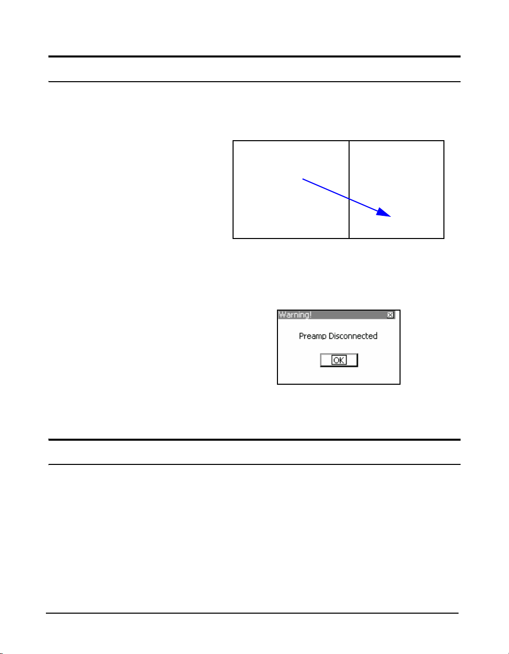
If the Model 831 is ON when the preamplifier is
disconnected, the Preamp Disconnected message box will
appear for several seconds.
Powering the Model 831
2-4 Disconnecting the Preamplifier Model 831 Manual
FIGURE 2-5 Disconnect The Preamplifier
5 clear the message box.
Press
The following section provides power information for the
model 831, including the following:
• Battery Power
• External Power Supply
• Power Up Operation
• Power Control Page
• Hardware Power Switch
Page 24

Battery Power
Full Charge
Low Charge
The Model 831 is compatible with AA nickel metal hydride
(NiMH), Alkaline or 1.5 Volt Lithium batteries. Energizer,
Duracell and other nationally recognized brands are the
preferred suppliers of alkaline batteries. These will provide
the user with the best battery life estimation. Sanyo,
Energizer and Ray-O-Vac, 2500 mAH, Lithium, AA, NiMH
batteries and their respective fast chargers are also
recommended.
WARNING:Do not mix Alkaline and NiMH batteries.
WARNING:Do not mix batteries from different
manufacturers
WARNING:Replace all four batteries when installing
fresh cells
WARNING:The correct battery type must be specified,
as described in "Battery Type" on page 18-5, based on
the battery type installed. Otherwise, serious damage,
injury or fire can occur when the battery type is set to
NiMH but Alkaline or Lithium batteries are installed
because the internal charger will be enabled. Alkaline or
Lithium batteries must not be charged.
Model 831 Manual Powering the Model 831 2-5
Battery Voltage an d Estimated Run Time are displayed on
the Power Control screen and the last page of the Live tab.
The battery icon indicates the state of the battery charge by
the width of the interior shaded portion. Figure 2-6 shows a
fully charged battery and a nearly discharged battery.
FIGURE 2-6 Battery Status Icons
A battery icon is always available in the status bar at the top
of the screen. The battery voltage and the state of the battery
Page 25

Low Battery
Inserting Batteries
icon directly reflect the remaining Estimated Run Time as
displayed by the instrument.
As the battery nears end-of-life (1% of capacity), the empty
battery symbol will begin to flash. The unit will shut down
in a short time because the battery voltage is too low.
When the battery is at the end-of-life, the Model 831 will
stop running, save all data and instrument status, then turn
off. When the unit is turned on again, with fresh batteries or
an external power supply, the unit returns to the state it was
in when it shut down.
If external power is supplied through the USB connector, the
battery icon is replaced with the External Power icon, as
shown in Figure 2-7.
FIGURE 2-7 External Power Icon
When external power is connected to the Model 831, the
unit is not dependent on batteries. The Estimated Run Time
calculation is valid only if there is no external power.
There are 2 tabs on the bottom of the
battery door that engage the case of
the Model 831.
2-6 Powering the Model 831 Model 831 Manual
The battery compartment of the Model 831 is located on the
back of the unit. There is a clip on the battery door. To
remove the battery door, place a finger on the clip and push
it downward towards the battery door while pulling away
from the body of the instrument. The battery door will pivot
away from the unit.
Page 26

Insert 4 fresh AA batteries as shown in FIGURE 2-8. Ensure
correct alignment of the batteries + and - terminals as
indicated by diagrams on the bottom of the battery
compartment.
FIGURE 2-8 Insert Batteries
After the batteries are installed, insert the two tabs on the
bottom edge of the battery door into the mating slots in the
case. Close the battery door, allowing the clip to snap in
place on the case.
Selecting Battery Type
The battery type is selected from the Power tab in System
Properties, as described in the section “Battery Type” on
page 18-5.
Charging Batteries On-board
When using NiMH batteries and powering the Model 831
from either the computer (via USB port) or from the
PSA029 power supply, or from another external source, the
batteries will be charged inside the instrument. The charge
time to completely recharge the cells is about sixteen hours
when the instrument is powered off. The batteries will be
charged while the instrument is powered on at a reduced rate
as long as the backlight and USB Host features are off.
Model 831 Manual Powering the Model 831 2-7
Page 27

Charge Status LED
External Power Supply
USB Port Power
The charge status is indicated by an LED beneath the power
key as follows:
• LED continuously lit: Charging
• LED not lit: Not charging
• LED flashing at 1/sec: Trickle charging. This is
typically done early in the charging cycle when the
battery is cold, or when the battery has been highly
discharged. The charge rate should increase when these
conditions improve.
The Model 831 can be powered from a variety of sources
including internal batteries, via the USB port from a
computer, via the USB port from the PSA029 power supply,
via the I/O port from the PSA027 power supply (using
CBL140 or CBL154), from an external +10.8 to +30 Volt
battery, or from an external +10.8 to +30 Volt mains power
source.
When powering the Model 831 by
external power, Larson Davis
recommends the Model 831-INT
System Interface Unit and the
appropriate Larson-Davis cable for
making the connection to the battery
or batteries.
The PSA029 is supplied with power
plug adaptors for most areas of the
world.
If the Model 831 is operated without
batteries installed and power is
interrupted, data may be lost.
2-8 Powering the Model 831 Model 831 Manual
When powered via the USB port by a computer, use of the
computer's USB power is negotiated with the host and
cannot be utilized until permission is granted by the host.
This means that the Model 831 must run on batteries until
allowed by the host to run on USB or external power. If the
batteries cannot provide sufficient power (flat cells) the
Model 831 may not power on. Ensure that the Model 831
has good batteries in order to turn on. If there are no
batteries installed in the instrument, it will use USB power
regardless of negotiation.
The Model 831 can be powered via the USB port with the
PSA029 external power supply. The PSA029 has an input
operating voltage range of 90 to 274 VAC and a power line
frequency range of 47 to 63 Hz. The output voltage from the
supply is 5 VDC. The PSA029 used a standard USB A to
Mini-B 5-pin cable which connects to the USB connector on
the bottom of the Model 831.
With the PSA029 power supply connected and operating at
rated conditions, the Model 831 will operate properly with
or without batteries installed.
Page 28
Low Voltage Shutdown
Power Outage
Sudden Loss of External Voltage
The Model 831 has a special feature to preserve the service
life of an external SLA (Sealed Lead-Acid) battery by
preventing it from being discharged excessively. When the
battery voltage drops below the external shutoff voltage
(default value +10.8 volts), but remains above +10.2 volts
for one minute, the instrument will stop, save data and turn
the Model 831 off.
In the event of power outage, unattended Model 831 meters
with serial numbers greater than 2089 will turn on
automatically in six hours as a recovery mechanism.
WARNING!
A sudden loss of power while the
Model 831 is storing data may lead
to hardware damage and should be
avoided. To avoid this, turn off the
Model 831 prior to turning off the
PC, or before unplugging USB
cables from the PC.
Power-Up Operation
Insufficient Battery Voltage
If the external voltage is suddenly lost, for example when
the external supply is disconnected or when mains power
fails and there is no external battery, the Model 831 will
continue to run on internal batteries if they are present and in
good condition. Without internal batteries, the Model 831
will shut-down and un-stored data may be lost.
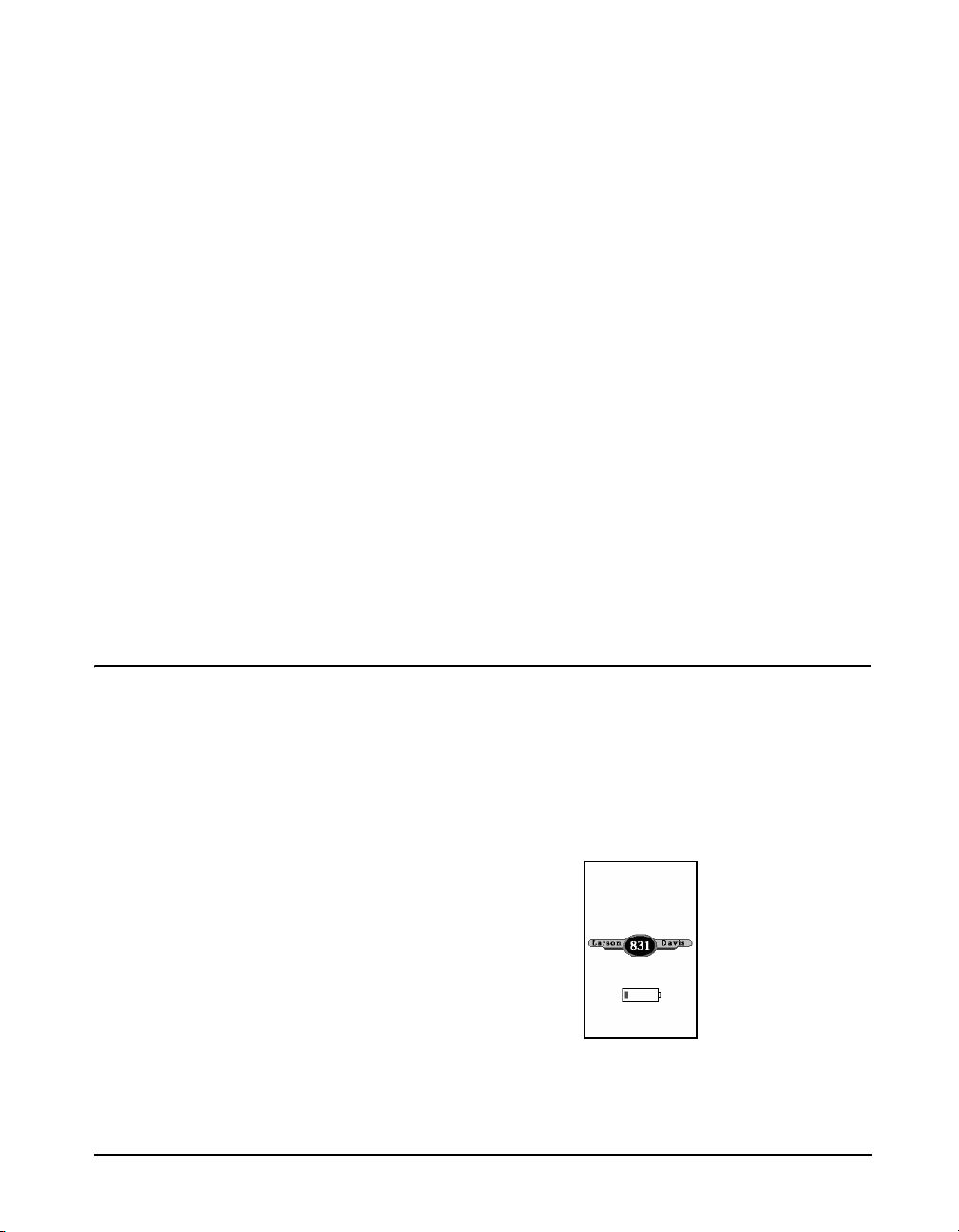
The Model 831 automatically detects its power source while
it is turning on and does not fully start if a problem is found.
If the internal battery is powering the instrument, i.e. there is
not USB or external power, and is less than ~4.2 Volts, the
display shown in FIGURE 2-9 appears with the grey box
inside
FIGURE 2-9 Insufficient Battery Voltage
Model 831 Manual Powering the Model 831 2-9
Page 29
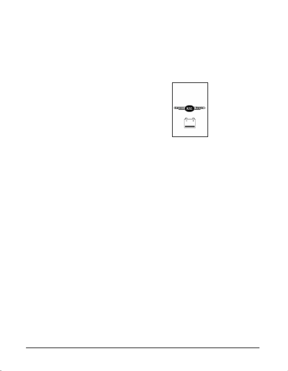
Insufficient External Voltage
If the external power source is operating the instrument, i.e.
there is no USB or internal battery power available, and is
less than about 10.8 Volts, the displa y shown in FIGURE 210 appears with the grey box inside the battery symbol
flashing on and off every second.
FIGURE 2-10 Insufficient External Voltage
If the power fault condition is not alleviated within 2
minutes, the instrument powers off. If a sufficient power
supply is provided for more than 10 seconds, i.e. USB or
Main power is connected, the instrument proceeds to turn
on.
2-10 Powering the Model 831 Model 831 Manual
Page 30
Power Control Page
The estimated battery run time is
only shown after running on
batteries for more than one minute,
which permits the battery voltage to
stabilize.
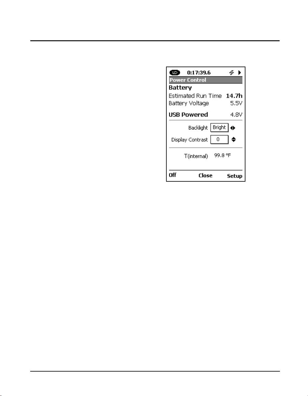
If the Model 831 is ON, pressing the
displays the Power Control screen.
FIGURE 2-11 Power Control View
Located on the first section of this screen is the Estimated
Battery Run Time (calculated using the voltage of the
installed batteries), Battery Voltage and the USB Powered
voltage.
0 (ON/OFF) key
For more information on Backlight
and Display Contrast, see the
"Backlight" on page 18-9 and
"Display Contrast" on page 18-9.
The units of the temperature display
are user-selectable, as described in
“Units” on page 18-22.
Model 831 Manual Powering the Model 831 2-11
Next, Backlight and Display Contrast are adjusted using
the 4, 6, 8 and 2 keys. Backlight provides three
options: Off, Dim and Bright, which are adjusted using the
4 and 6 keys. The Display Contrast has a range of -9 to 9,
which is adjusted using the 8 and 2 keys.
The last section displays the Model 831 internal temperature
that is used to automatically adjust the contrast of the display
to compensate for temperature changes.
Page 31

Hardware Power Switch
DO NOT use the hardware power
switch to turn the Model 831 OFF.
This may cause data to be lost and
permanent damage may occur. Press
0 key for several seconds to
the
turn off the meter.
The Hardware Power Switch on the bottom of the Model
831 disconnects the batteries from the Model 831 hardware.
The real-time clock will maintain its value for six minutes,
enough to implement a battery change. This prevents battery
drain when the Model 831 is not in use for an extended
period of time (
in the "0" position, the batteries are disconnected.
After installing batteries be sure to move the switch to the "|"
position. This applies power to all of the Model 831
hardware.
The Hardware Power Switch should not be used to turn the
Model 831 ON and OFF. If the Hardware Power Switch is
used to turn the Model 831 OFF, data may be lost.
weeks)If the Hardware Power Switch is
2-12 Powering the Model 831 Model 831 Manual
Page 32

CHAPTER
Microphone
Preamplifier
LCD Display
Keypad
Connectors
Overview
3
831 Components
This chapter provides an overview of the components,
displays, and functions of the 831 sound level meter.
The standard Model 831 shown in FIGURE 3-1 includes the
following:
• 1/2 in. diameter condenser microphone
Model 831 Manual Overview 3-1
• PRM831 microphone preamplifier
• Backlit graphic 160 x 240 pixel LCD display
• 13-key soft rubber backlit keypad
FIGURE 3-1 The Model 831
Page 33

• AC/DC output, control, USB, and external power
Hardware Power Switch
USB Interface
AC/DC Output and Headset
I/O Connector for 831-INT, External
Power, Analog and Logic I/O.
AUX Connector
for USB
connectors (shown in FIGURE 3-2)
• True “hand held” instrument with “sure grip” pads
FIGURE 3-2 shows the bottom view of the Model 831.
FIGURE 3-2 Model 831 Bottom View
DO NOT use the hardware power
switch to turn the Model 831 ON or
OFF. This will cause data to be lost.
The purpose of this switch is to
disconnect the batteries for storage
(1 to 2 weeks). It is recommended
that the batteries be removed from
the instrument if it will not be used
for a month or longer (the batteries
may self-discharge and leak,
damaging the instrument).
3-2 831 Components Model 831 Manual
• Hardware Power Switch: When set to “O”, completely
• USB Interface: USB 2.0 peripheral full-speed port used
• AC/DC Output and Headset Jack: used to output
• AUX Connector for USB: intended for use with USB
powers down the Model 831 for storage. However, the
real-time clock will maintain its value for six minutes,
long enough to complete a battery change. Set to “|” for
instrument operation.
for communication with a PC, control of the Model 831
from the PC and downloading of data from the Model
831 to the PC. The PSA029 external power supply may
be connected here. The maximum USB cable length is 5
m and the cable is part number CBL138.
analog AC and DC signals or to connect to a headset for
the recording and playback of voice records.
mass storage, cellular & dial-up modems, GPS and
future devices.
Page 34

• I/O Connector for Peripherals and External Power:
typically used with external devices. For more
information, see “I/O Connector Specification” on
page A-9:
•CBL143 and CBL151 cables: these cables permit the
Model 831 to be powered from external 12 V batteries
•CBL154 cable: used to obtain power from a battery
when used with the 426A12
•831-INT: integrates the Model 831 with outdoor
microphone units (426A12 and PRM2100K) and
weather transducers
•426A12 and PRM2101K: Model 831 provides control
signals to these outdoor microphone units when not
used with 831-INT
Microphones and Microphone Preamplifiers
The Model 831 is designed for use with prepolarized
microphones. The following microphone preamplifier is
used:
For information on using the Model
831 with the PRM2103 preamplifier,
see the PRM2103 Manual.
• PRM831 1/2” Microphone Preamplifier
The most commonly used microphones, which can be used
with either of these preamplifiers are as follows:
• 1/2” Free Field Microphone with nominal sensitivity of
50 mV/Pa
• 1/2” Random Incidence Microphone with nominal
sensitivity of 50 mV/Pa
• 1/4” Free Field Microphone with nominal sensitivity of
3.16 mV/Pa (ADP043 adaptor required)
• 1/4” Pressure Microphone with nominal sensitivity of 1
mV/Pa (ADP043 adaptor required).
There are two equivalent electrical impedance adaptors
available. These are discussed in Chapter 1 "Optional
Accessories" on page 1-5.
Display
The Model 831 has a 160 x 240 graphic, liquid crystal
greyscale display. The display is backlit to provide
Model 831 Manual 831 Components 3-3
Page 35

comfortable viewing in most ambient light situations.
Measurement
Name
OBA Overload or
Under Rang Icon
Input Overload or
Under Range Icon
Run Time
Measurement
Status
Power Indicator
Tabs
Data Graph
Section
Indicator
Scroll Bar
Stability
Indicator
Left
Center
Softkeys
Right
Controls are provided for contrast and backlight
adjustments.
When the Model 831 is first switched ON, the Live tab
appears. When a measurement is in progress, a display
similar to Figure 3-3 is shown.
FIGURE 3-3 Data Display Screen
3-4 831 Components Model 831 Manual
Page 36

Keypad
SOFTKEYS:
Left
Center
Right
RUN/PAUSE
STOP/STORE
UP
RIGHT
DOWN
LEFT
RESET
TOOLS
POWER
The 831 meter has a 13 button keypad. This section
describes the buttons on the keypad.
FIGURE 3-4 shows the 831 keys.
Softkeys
FIGURE 3-4 Model 831 Keys
The three push button keys just beneath the display, on the
body of the Model 831, are called Softkeys.
Figure 3-5 shows the softkeys.
.
Model 831 Manual 831 Components 3-5
Page 37

Hardkeys
FIGURE 3-5 Softkeys
The function of each Softkey is indicated by an icon or label
on the bottom of the display. Softkeys are so named because
the function of each key can change depending upon the
screen, the context, or how it is programmed, as indicated by
the label. Pressing any one invokes the action associated
with the text or symbol directly above it on the screen.
The ten remaining keys below the softkeys are described in
Table 3-1.
The POWER key is used to turn the Model 831 ON and OFF when the
Hardware Power Switch, on the base of the unit is in the “|” position. T o turn the
831 off or on, press and hold the power key for a few seconds.
The Navigation keys; Up, Down, Left and Right are multipurpose keys used to
navigate through the Data Views, highlight icons and defined areas on the
display, make a selection from multiple options, and to input alphanumeric
characters into data fields.
The ENTER key is used to implement data entry associated with selections from
multiple options or the input of alphanumeric characters into data fields.
The RUN/PAUSE key is used to initiate and pause a measurement, and to
continue a paused measurement. This key has a green LED behind it which can
be illuminated to indicate the measurement state of the Model 831.
For more detailed information on the RUN/PAUSE key, see "Starting the
Measurement" on page 7-5.
The STOP/STORE key is used to stop a measurement and to store a
measurement when the measurement is stopped. This key has a red LED behind
it that can be illuminated to indicate the measurement state of the Model 831.
For more detailed information on the STOP/STORE key, see "Starting the
Measurement" on page 7-5.
Table 3-1 Keypad Hardkeys
3-6 831 Components Model 831 Manual
Page 38

The RESET key is used to reset a measurement. For detailed information on
Full Charge
Low Charge
using the Reset key, see "Resetting the Measurement" on page 7-13.
The TOOLS key is used to set a number of parameters not associated with a
specific measurement, such as setting date and time, managing power options
and setting personal preferences (i.e. language, decimal and date formats, etc.).
Table 3-1 Keypad Hardkeys
Summary of Displays and Icons
Tabs
Data is presented in tabbed format. Move between tabs by
using the right and left Softkeys.
Page
Tabs are divided into pages that logically group the data
together (i.e., 1/3 Octave data on the Live tab). Tabs may
contain only one page or multiple pages. Navigate up or
down to different pages by using the 8 (UP) or 2
(DOWN) keys. The position of the scroll bar indicates the
sequence of pages on tabs.
Scroll Bar and Section Indicator
The scroll bar represents the complete tab. The section
indicator shows the location of the page you are viewing.
Power Indicator
The following icons indicate the power source driving the
Model 831 and the supply available to operate it.
Battery Power
The battery icon indicates the state of the battery charge by
the width of the interior shaded portion. The two icons in
FIGURE 3-6 indicate a fully charged battery and a nearly
discharged battery.
Model 831 Manual Summary of Displays and Icons 3-7
FIGURE 3-6 External Power
Page 39

Measurement Name
Stability Indicator
Run Time
Input Overload Icon
The external power connection icon appears when the
Model 831 is powered from an external power supply or via
the USB port.
This is the file name to be used for the data file.
Presented in the form of an analog display , this dynamic icon
indicates the trend in the measured overall Leq, indicating if
the measured signal is rising, decaying or holding stable.
The icon appears in the first section of the Live, Overall and
Current displays, and also in a window that appears during a
sound level calibration.
This is the amount of time the measurement has been
running.
When a signal from the preamplifier exceeds the calibrated
input range of the Model 831, the Input Overload Icon will
appear. While the overload is present, the icon will flash.
If a measurement is running and an overload occurs, the icon
shown below will flash during the overload.
When the overload has been removed, the icon will still be
present (not flashing) to indicate that an overload has
occurred during the measurement. A reset will clear the icon
from the display.
3-8 Summary of Displays and Icons Model 831 Manual
Page 40

Under Range Icon
Normal Range
Under Range
When using a microphone having a sensitivity of 50 mV/Pa,
the input overload will occur approximately as shown in
Table 3-4.
Input Gain, dB Overload Level, dB Peak
0 143
20 123
Table 3-4 Input Overload Levels
When the signal from the preamplifier drops to the point
where the noise level of the instrument and the preamplifier
influence the measurement, an under range condition exists.
When this happens the Under Range Icon will appear.
As long as the under range condition exists, the icon will
flash. When the measured level no longer produces an under
range condition, the icon will be removed from the display.
At any time when a measured parameter is in an under range
condition, it’s numeric display will appear in grey rather
than the usual black, as shown FIGURE 3-7.
OBA Overload Icon
Model 831 Manual Summary of Displays and Icons 3-9
FIGURE 3-7 Normal vs Under Range Data Display
If the input to the Octave Band Analyzer (optional firmware
831-OB3 required) becomes overloaded, the icon shown
will appear to indicate the overload.
This icon operates similar to the Input Overload Icon shown
in the above section "Input Overload Icon".
When the OBA Range property is set to Low, the OBA
Overload Icon will activate at a level 33 dB lower than it
would had the OBA Range been set to Normal.
Page 41

OBA Under Range Icon
When using a microphone having a sensitivity of 50 mV/Pa,
the input overload will occur approximately as shown in
Table 3-5.
Input Gain, dB OBA Range Overload Level, dB
0 Normal 143
20 Normal 123
0 Low 110
20 Low 90
Table 3-5 OBA Overload Levels
When the signal from the preamplifier drops to the point
where the noise level of the instrument and the preamplifier
influence the measurement, an under range condition exists.
When all filters of the OBA are “under range” the OBA
Under Range Icon appears.
As long as this under range condition exists, the icon will
flash. When the measured OBA levels no longer produces
an under range condition, the icon will be removed from the
display.
Like the SLM, when a measured OBA parameter is in an
under range condition, it's numeric display will appear in
grey rather than the usual black, as shown Figure 3-8.
FIGURE 3-8 OBA Under Range Display
Measurement Status
Reset Icon
The Reset Icon indicates that a reset has occurred.
3-10 Summary of Displays and Icons Model 831 Manual
Page 42

Run Pending Icon
The Run Pending icon appears when the
PAUSE) key is pressed and the Model 831 is waiting for
filters and detector initialization to complete. The Model
831 will automatically start the run after the wait or warmup state is completed (less than 10 seconds)
Run Icon
The Run Icon moves from left to right to indicate that a
measurement is running.
Pause Icon
The Pause Icon indicates that the present run has been
paused.
Stop Icon
A Stop Icon is displayed when a measurement has been
stopped.
Store Icon
9 (RUN/
When a data file has been stored, the Store Icon is displayed.
USB Copy Indicator
When a data file is being copied to the USB port, the USB
Copy Indicator Icon is displayed in the upper left corner in
place of the PCB Piezotronics logo.
Power Save Icon
When the Model 831 is in the power save mode, the power
save icon
will be displayed in the location where the measurement
status icons usually appear. For more detail on power save,
see Power-Save T ime on page 18-7.
Model 831 Manual Summary of Displays and Icons 3-11
Page 43

Changing Views
In the Data Views, the labels of the Left and Right Softkeys
are left and right arrow symbols, respectively. These indicate
that the Left and Right Softkeys are used to scroll the
selection of the tab being displayed in the corresponding
direction. One press of the Right Softkey will bring up the
Session Log View, and a second press will bring up the
Current tab. Then, sequential presses of the Left Softkey will
bring up the Session Log View, then the Overall tab.
Navigating and Selecting
To navigate between tabs on the display, press the right or
left Softkeys. To navigate within tabs, use the 4 and 6 keys
for moving horizontally on screens. This includes moving
the highlight from one property to the next.
The 8 and 2 keys are used for moving vertically on
screens. This includes moving the highlight from one
property to the next and to move to prev ious or subsequent
tabs.
These keys are also used for character entry by navigating
through lists of characters in text boxes.
The
selections completing actions, or accepting values.
5 (ENTER) key is typically used for completing
Basic Run Functions
The basic measurement run functions are as follows:
• Running
•Pausing
• Stopping
•Storing
The
9 (RUN/PAUSE) key initiates a run. If a
measurement is running, this key pauses the run. It does not
end the run; to end the measurement run, press the
(STOP/STORE) key. Pressing the 9 key when the unit is
PAUSED continues the run. This key is only active on a
Data View screen.
3-12 Navigating and Selecting Model 831 Manual
7
Page 44

Pressing the 9 (RUN/ PAUSE) key
when the unit is in STOP mode
continues the previous run.
The 7 key ends a run. Pressing the key a second time
stores the data in a file. This key is only active on a Data
View screen.
Tab and Setting Displays
The 831 features and functions are organized into four
different types of displays.
• Data Display tabs: used to display measured data.
• Measurement Settings tabs: used to set the parameters
• Control Panel (Tools) Properties: used to set user
• Power Control Page: used to check battery power,
Data Display Tabs
When the
the Data Display tabs appear.
Measurement Settings Tabs
for a measurement.
preferences, to set non-measurement related parameters,
and to implement calibration.
control the contrast and backlight of the display and
other features.
0 (ON/OFF) key is pressed to turn on the 831,
Opening
From the Data Display tabs, pressing the Center Softkey
labeled Menu brings up the menu shown in FIGURE 3-9.
FIGURE 3-9 Menu
Select Settings and press
Closing
Press the Center Softkey to return the Data Display tabs.
Control Panel (Tools) Properties
The Control Panel is accessed by pressing the
key at the lower right of the 831 front panel. To exit from the
Model 831 Manual Tab and Setting Displays 3-13
5 to open the Settings tabs.
3 (TOOLS)
Page 45

Power Control Page
Data Display Tabs
Control Panel and return to the Data Display tabs, press the
Center Softkey labeled Close.
The Power Control Page is opened by pressing the
/ OFF) key while on Data View tabs. To exit from the Power
Control Page, press the Center Softkey labeled Close.
The Data Display tabs are identified by their titles on each
tab. You can navigate from tab to tab by pressing the left and
right Softkeys.
• Live tab: Data is continuously displayed on this tab
whether there is a measurement in progress or not.
0 (ON
Pressing the Pause key does NOT
pause the elapsed time indicator.
This description of the Data Display
tabs corresponds to the LD default
setup used when the Model 831 is
delivered from the factory. These
display tabs can be modified, as
described in “Displays” on page 18-
23.
For a more detailed description of
the Data Display tabs and their
associated views, see Chapter 5
"Data Display" on page 5-1
• Overall tab: The data displayed on this tab represents
data measured and averaged beginning from the time the
measurement was started by pressing the Run key until
the elapsed time indicated above the display. If the Stop
key is pressed, the elapsed time will be stopped.
However, pressing the Run key again will continue this
overall measurement as shown by the elapsed time
restarting from the time when it had previously been
paused or stopped. As long as there is no reset, the same
measurement is continued.
• Session Log: The Session Log is a record of data
accumulation actions. Resetting and storing data will
clear the session record. A time-stamped record is made
for every Run, Pause, Resume, Stop, Voice Message and
Sound Recording action. The source responsible for each
action is also recorded.
• Current: Unless Measurement History has been enabled
in the Run Control setup, the Current View display is
similar to the Overall View. The difference is that while
the Overall View displays data measured since the last
pressing the Run key following a reset, the Current View
displays data measured since the last press of the key
sequence Stop/Run. For example, suppose a
measurement was begun at a time T1 and then the key
sequence Stop/Run was pressed at a later time T2. The
3-14 Tab and Setting Displays Model 831 Manual
Page 46

data presented in the Overall View would represent the
measurement since T1 while the Current View would
represent the measurement since T2.
With measurement history enabled, a series of separate
measurements are made based on either manual key
presses or time intervals, depending on the setup used.
The current view will display the data corresponding to
the measurement currently in progress. When that
measurement is complete, the data are transferred to the
measurement view. The current measurement is then
reset and the subsequent measurement begun, at which
time the data for this new measurement is displayed.
• Measurement: With Measurement History enabled, the
measurement view can display all the separate
measurements made from the beginning to the end of the
total measurement period.
The 831-ELA firmware option must
purchased and enabled for this tab
to appear.
The 831-LOG firmware option must
be purchased and enabled for this
tab to appear.
Measurement Settings Tabs
Because the screen is not wide
enough to show tall Measurement
Settings tabs at the same time, use
the Right and Left Softkeys to scroll
the view to the right or left
respectively.
• Events: Basic data associated with measurements
initiated by the trigger criteria are displayed in the view.
When there have been multiple measurements, these data
can be viewed separately.
• Time History: This view displays data measured using
the time history measurement feature.
Additional tabs appear in different instrument modes when
the 831-FFT and 831-RT options are enabled. For more
information, refer to the "FFT and Tonality" and "RT-60"
chapters.
The Measurement Settings tabs allow for specific settings.
From any data tab, press the Menu softkey, select Settings
and press
measurement. Yo u can navigate from tab to tab by pressing
the left and right Softkeys.
•\General: used to create a file name and a measurement
description
• SLM: used to setup the parameters for the measurement
of sound levels
5 to open the settings tab for the current
Model 831 Manual Tab and Setting Displays 3-15
Page 47

• OBA (optional): used to setup the real-time octave band
frequency analysis
• Dosimeter 1 (optional): used to setup the parameters for
the measurement of sound exposure and noise dose
• Dosimeter 2 (optional): used to setup the parameters for
the measurement of sound exposure and noise dose
• Ln: used to define the parameters for the measurement
of Ln statistics
• Control: used to setup the mode of measurement timing
and the storage of measurement history records
For more information on the
Measurement Settings tabs and their
associated pages, see Chapter 4 on
Page 4-1.
• Time History (optional): used to setup the timing and
select the metrics that are stored in the time history
• Triggers: used to setup the triggers which define noise
exceedance events
• Event History (optional): used to setup the timing and
options for event details
• Markers: used to define the marker names and enable
sound recorder options
• Day/Night: used to define the time periods and level
penalties for community noise metrics
• Sound (optional): used to set the quality of sound
recording and enable its usage
• Weather: used to setup external transducers for the
measurement of wind speed, wind direction, temperature
and humidity
3-16 Tab and Setting Displays Model 831 Manual
Page 48

Control Panel (TOOLS) Properties
For a detailed description of the
Tools Screen, see “Control Panel System Properties” on page 18-1.
Three more icons, Lock, System
Utilities and Communication do not
appear in FIGURE 3-10. Scroll
down below the System Properties
and About icons to see them.
The Control Panel displays icons to represent the different
functions available for the Model 831. Pressing the
(TOOLS) key displays the Control Panel screen, as shown in
FIGURE 3-10. Press
5 to select an icon.
FIGURE 3-10 Tools Screen
3
Data Explorer
For a detailed description of the
Data Explorer, see Chapter 17 "Data
Explorer" on page 17-1.
Setup Manager
For a detailed description of the
Setup Manager, see “Setup
Manager” on page 4-16.
System Properties
For a detailed description of the
System Properties tabs, see Chapter
18 "System Properties" on page 18-
1.
Model 831 Manual Tab and Setting Displays 3-17
Data Explorer is used to examine stored data. It is also used
to manage stored measurements such as rename or delete
files.
The Setup Manager permits the user to create and store a
number of user-defined measurement setups for easy recall,
editing and use.
System Property tabs are used for general instrument
bookkeeping. Functions such as setting the instrument date
and time, display contrast adjustment, date format, etc. are
located here. These are single-paged tabs.
The System Property tabs include the following:
Page 49

• Device: Enter instrument identification.
Device Time Power Preferences Localization Displays Logic I/O
Softkey Selection of Systems Property Pages
• Time: Set date and time.
• Power: Set controls affecting power consumption.
• Preferences: Set a variety of system parameters such as
Autostore and USB Storage.
• Localization: Set the regional characteristics, such as
Language, Decimal Symbol, Date Format and Units.
• Displays: Set customization of Displays.
• Logic I/O: Configure logic in and logi c out options for
the Model 831 control port.
FIGURE 3-11 shows System Properties tabs sequence.
FIGURE 3-11 System Property Tabs
The Right and Left Softkeys are used to scroll between
System Property tabs.
Lock
For a detailed description of the
Lock feature, see Chapter 21 "Lock/
Unlock the Model 831" on page 21-
Lock permits the Model 831 to be configured such that
certain keys are locked so their functionality cannot be
utilized.
1.
Communication
For a detailed description of the
Communication tabs, see Chapter 20
"Communication" on page 20-1.
The Communication tabs are used to setup and monitor
communications between the Model 831 and a PC using a
dial-up modem, wireless EDGE modem or RS-232
interface.
3-18 Tab and Setting Displays Model 831 Manual
Page 50

Calibrate
The Communication tabs include the following:
• Status: Display status of Analog and Wireless modems,
RS-232 and USB channels.
• Modem: Setup a dial-up modem
• Wireless: Setup a wireless modem
• RS-232: Setup an RS-232 interface
For a detailed description of the
calibration procedure, see Chapter 8
"Calibration" on page 8-1.
Voice Recorder
For a detailed description of the
voice recording feature, see Chapter
10 "Voice Recording" on page 10-1.
About
For a detailed description of the
About tabs, see Chapter 22 "About"
on page 22-1.
Calibrate is used to verify and adjust the calibration of the
Model 831 prior to a measurement.
A method to allow voice annotation of the data is described
in Chapter 10 "Voice Recording" on page 10-1.
The About tabs provide the user with information specific to
this instrument such as serial number, options, etc. These are
single section tabs.
The About tabs include the following:
• About: shows information such as serial number and
firmware revision
• Standards: lists the standards that the Model 831 meets
• Options: shows the options that are available in this
instrument
• User: user entered instrument identification
Model 831 Manual Tab and Setting Displays 3-19
Page 51

System Utilities
About Standards Options User
Softkey Selection of About Pages
FIGURE 3-12 shows the About tabs sequence.
FIGURE 3-12 Softkey Selection of About Tabs
The Right and Left Softkeys are used to scroll between the
About tabs.
For a detailed description of the
System Utilities, see Chapter 23
"System Utilities" on page 23-1.
Additional icons may appear in the
Control Panel, depending on the
firmware options enabled on your
Model 831.
Parameter Selection
The System Utilities provides routines to work with the
internal files systems and the USB. Routines are provided to
implement the following activities:
• Check File System
• Format
• Format/Restore Defaults
• Check/Repair USB
• Format USB
When operating the Model 831, you frequently define
parameters by selecting them from lists that may appear on
the display either as a row with a radio button, or as a
vertical list in a drop down menu.
3-20 Parameter Selection Model 831 Manual
Page 52

Parameters in a Row
These may appear as a single row or, when there are
numerous parameters to define, as multiple rows as shown
in FIGURE 3-13.
FIGURE 3-13 Parameters with Radio Buttons
Use the 2 and 8 keys to highlight the parameter
(Frequency Weighting, Detector, etc.), then the 6 and 4
keys to highlight the desired selection for that parameter.
5 to make the selection and fill in the radio button
Press
associated with that parameter.
Model 831 Manual Parameter Selection 3-21
Page 53

Drop Down List
Parameters of this type are associated with a parameter name
followed by a data field indicating the present selection for
that parameter. There may be a single parameter to be
defined, or multiple parameters as shown in FIGURE 3-14.
FIGURE 3-14 Parameter Data Field
Use the 2 and 8 keys to highlight data field of the
parameter to be defined (Battery Type highlighted above)
and press
permitted choices as shown in FIGURE 3-15.
Use the 2 and 8 keys to highlight the desired item in
the list and press
menu.
3-22 Parameter Selection Model 831 Manual
5 to open the drop down menu listing the
FIGURE 3-15 Drop Down Menu
5 to make the selection and close the
Page 54

Entering Alphanumeric Strings
It is easier to specify alphanumeric
strings in SLM Utility-G3 or G4
software.
In some instances you will be called upon to enter
alphanumeric strings, such as creating a name or entering
text information. Parameters of this type are associated with
a parameter name and a data field as shown in FIGURE 3-
16.
.
FIGURE 3-16 Alphanumeric Data Field
The data field may be blank, as in the Measurement
Description above, or it may contain a default name, as in
the Default Data File field. Use the 2 and 8 keys to
highlight the desired data field and press
cursor in the data field as shown in FIGURE 3-17.
FIGURE 3-17 Cursor in Data Field
The 6 and 4 keys are used to move the cursor right or left,
respectively. At any cursor position, the 8 and 2 keys
are used to scroll the alphanumeric character appearing in
that position through a defined sequence.
Model 831 Manual Parameter Selection 3-23
5 to bring up a
Page 55

Entering Numeric Data
Repeated presses of the 8 key will produce the following
sequence of characters:
• Capital letters A through Z
• Lower case letters a through z
• Characters ! @ # $ * ( ) - + = [ ] < > .
• Numbers 0 through 9
•Space
Repeated presses of the 2 key will produce the same
sequence in reverse order.
When the desired alphanumeric field has been entered, press
5 to accept it and remove the cursor.
FIGURE 3-18 Entering Numeric Data
When a purely numeric parameter is being entered, as in
FIGURE 3-18, the same procedure is followed as for
alphanumeric parameters. In this case, repeated presses of
the 8 and 2 keys will scroll upward or downward,
respectively, through the numeric sequence.
3-24 Parameter Selection Model 831 Manual
Page 56

CHAPTER
Basic Measurement Setup
4
Settings Screen
Accessing the Settings Screen
For a more detailed description of
the Settings Screen, see “Control
Panel (TOOLS) Properties” on
page 3-17.
This chapter describes the setup of the Model 831 to
perform basic sound level measurements. These
measurements may include the following:
• Leq, Lmax, Lmin corresponding to user-selected
values of frequency weighting and detector
• Lpeak and Lpeak(max) corresponding to a userselected value of frequency weighting
• 1/1 and/or 1/3 Octave real-time spectra
(831-OB3 required)
• Six values of Ln based on six user-selected values of
the percentage parameter n
• Count of the number of times the levels (SPL and
Peak) exceeded user-selected threshold values
• Sound exposure and sound exposure level data
The parameters defining a measurement are set from the
Settings Screen.
This screen can be accessed from any of the Data Views.
Press the Center Softkey labeled Menu, highlight Settings,
and press
displayed with the tab selected that is most appropriate for
the data display from which it was activated.
The settings can also be edited using the Setup Manager,
described in “Setup Manager” on page 4-16.
5 (ENTER). The Settings Screen is now
Model 831 Manual Basic Measurement Setup 4-1
Page 57

Settings In Use Message
If the Model 831 is not connected to
a computer running G4 LD Utility
software, ignore this section.
Setup Tabs
Only a few of these horizontally
arranged tabs (three in Figure 4-2)
can be seen at one time. To see those
off-screen to the right use the Right
Softkey beneath the display. To scroll
back to the left, use the Left Softkey
beneath the display.
If the G4 is connected to the Model 831 when attempting to
access the Settings Screen, the display shown in FIGURE 41 will appear.
FIGURE 4-1 Settings In Use By 831 Utility Message
This message warns the user that accessing the Settings
Screen will cause setup changes which had been made using
the 831 Utility during this session to be lost. It also indicates
that changes made in the instrument may be lost when the
settings in use by the PC are uploaded.
To continue and access the Settings Screen, highlight Yes
and press
Depending on the firmware options loaded in the Model
831, there may be as many as fourteen different setup tabs in
the Settings Screen, each identified by a title on a tab at the
top as shown in Figure 4-2.
5.
FIGURE 4-2 Tabbed Setup Tabs
For basic measurements, we will only be concerned with the
following tabs:
• General
•SLM
•OBA
•Ln
4-2 Setup T abs Model 831 Manual
Page 58

General Tab
• Control
• Triggers
• Day/Night
The Right and Left Softkeys are used to scroll through the
available tabs, to the right and left, respectively, in the order
they are listed above.
Each of these is described in detail in the sections which
follow.
FIGURE 4-3 General Tab
The 831 Utility Software can be used
to easily enter both the file name and
the measurement description.
Model 831 Manual Setup Tabs 4-3
The General Tab is used to enter a file name and a
measurement description for the measurement being
defined. Upon opening, the Default File Name “831_Data”
may appear in the file name field.
To enter a new file name, highlight the Default File Name
text box and press
5. Enter a new name and press 5.
Page 59

SLM Tab
The default values for these
parameters are as shown in
FIGURE 4-4.
Frequency Weighting
Time Weighting
FIGURE 4-4 SLM Tab
Selections of Frequency Weighting, Detector, Peak
Weighting and Integration Method are made one-at-a-time.
Click to highlight the desired section prior to making the
selection.
Use the arrow keys to highlight the appropriate item for the
selected parameter and press
A, C and Z frequency weightings are provided for the SPL
and peak detectors. These are selected separately.
Available time weightings for the SPL detector are: Slow,
Fast and Impulse.
5 to make the selection.
4-4 Setup T abs Model 831 Manual
Page 60

Integration Method
Note that the Model 831 can be set to
run for a preset integration time as
described in "Manual Stop, Timed
Stop or Stop When Stable" on page
6-4
20 dB Gain
Two Integration methods are available: Linear and
Exponential.
Exponential Integration
Exponential integration is provided mainly to provide
compatibility with older instruments. Exponential detectors
have a tendency to hide small events in the long decay of a
loud impulsive event.
Note that when performing time history measurements using
time increments 10 ms or less, the integration method must
be linear. If exponential integration has been selected at the
time of setup, this will be changed as described in “Linear
Integration Only” on page 11-6.
Linear Integration
Linear integration integrates only energy that occurs during
a given time period and therefore does not exhibit the decay
slope of a Fast, Slow or Impulse exponential detector.
The value of the integrated level is displayed immediately
following the end of the integration time.
For long duration measurements both integration methods
report the same value in that they both have equivalent
“energy under the curve”, although short term metrics may
vary.
When measuring low level sounds, when the sound level is
approaching the background noise level of the instrument, it
is recommended to increase the gain by 20 dB. This is done
by using the
2 key to highlight this sect ion and pressing
5 to insert a check. Press 5 again to remove the check
and set the gain back to 0 dB
The effect of the gain on the noise level is shown in
FIGURE A-27 "Noise of Model 831 with 377B02: 0 dB
Gain, Low Range” on page A-48, FIGURE A-28 "Noise of
Model 831 with 377B02: 0 dB Gain, Normal Range” on
page A-49, FIGURE A-29 "Noise of Model 831 with
377B02: 20 dB Gain, Low Range” on page A-50 and
FIGURE A-30 "Noise of Model 831 with 377B02: 20 dB
Gain, Normal Range” on page A-51.
Model 831 Manual Setup Tabs 4-5
Page 61

The effect on the A-We ig hted linearity range is shown in the
Highlight and Press 5
Key to Select
section “f) Linear Operating Range” on page B-9.
Octave Band Analyzer Tab (Optional)
The default values for these
parameters are as shown in
FIGURE 4-5.
OBA Parameter Selection
This tab will only appear when the Model 831 has the
optional 831-OB3 firmware enabled.
FIGURE 4-5 OBA Tab
The OBA parameters are selected as shown in FIGURE 4-6.
4-6 Setup T abs Model 831 Manual
FIGURE 4-6 OBA Parameter Selection
Page 62

OBA Range Setting
In the Low range, the full scale level is reduced by 33 dB on
the display. The default display ranges will be as follows:
• Normal Range: 20 to 140 dB
•Low Range: -10 to 110 dB
However, the graph scaling range can be modified by the
user as described in “Adjust Graph Scale” on page 5-29.
OBA Bandwidth Setting
The user can select to utilize a single 1/1 Octave analysis
module, a single 1/3 Octave analysis module or both
simultaneously.
Select Off to have no real-time analysis module active.
OBA Frequency Weighting
The user can select that the 1/1 and/or 1/3 Octave frequency
analysis modules process data from the A, C or Z weighting
filters.
See “Spectral Statistics” on
page 24-5 for a more detailed
description of spectral Ln
measurements.
Ln Tab
Spectral Ln Mode
Spectral Ln values can be measured using either 1/1 or 1/3
octave bandwidths, depending on the OBA bandwidth
selected, as shown below.
• OBA = 1/1 Octave: Spectral Ln Mode is 1/1 Octave
• OBA = 1/3 Octave or 1/1, 1/3 Octave: Spectral Ln
Mode is 1/3 Octave
Setting the spectral mode Off will reduce the memory used
for data storage.
The Ln value is the measured sound level which was
exceeded n% of the measurement time. For example, a value
= 35 dB means that the measured sound level was
of L
90
above 35 dB for 90% of the measurement period. These
statistical values are commonly used to describe the
characteristics of non-steady sound such as environmental
noise.
In order to be able to calculate Ln values, the Model 831
creates an amplitude distribution table over the range 0 to
200 dB, in amplitude increments of 0.1 dB. These data
Model 831 Manual Setup Tabs 4-7
Page 63

Selection of Ln Values
permit the calculation of Ln values for any value of n in the
range 00.01 to 99.99%.
The default values for these
parameters are as shown in
FIGURE 4-7.
Modifying Ln Values During a Measurement
The Model 831 displays six Ln values at a time, using userselected values of n. These are set from the Ln Tab, shown
in FIGURE 4-7.
While a measurement is running, it is possible to return to
the Ln display of the Settings Screen, shown in FIGURE 4-7
and change any or all of the six Ln values. This will change
the display of Ln values, shown in FIGURE 5-18 "Overall
Tab: Ln Percentiles” on page 5-18.
FIGURE 4-7 Ln Tab
4-8 Setup T abs Model 831 Manual
Page 64

Control Tab
FIGURE 4-8 Control Tab
A detailed description of the Run
Mode is presented in Chapter 6 "Run
Control” on page 6-1.
The Control tab is used to set the Run Mode for the
measurement to be performed. There are six modes of
measurement duration available. In this chapter we will
address only the first three.
•Manual Stop: The measurement is initiated manually by
pressing the
pressing the
•Timed Stop: The measurement is initiated manually by
pressing the
automatically after a user-defined time period.
• Run Until Level Stable: The measurement is initiated
manually by pressing the
measurement will stop when the measured level has
remained within a user-defined range and the
measurement has run for a user-defined time period.
The selection of the Run Mode and the associated
parameters is shown in FIGURE 4-9. The Measurement
History feature is not discussed in this chapter. For further
information on that, see Chapter 12 "Measurement History”
on page 12-1.
9 (Run/Pause) key and it stopped upon
7 (Stop/Store) key.
9 (Run/Pause) key and will be stopped
9 (Run/Pause) key. The
Model 831 Manual Setup Tabs 4-9
Page 65

Measurement History
FIGURE 4-9 Run Mode Parameter Selections
For a detailed description of
Measurement History, see Chapter
12 "Measurement History” on
page 12-1.
Manual Stop Mode
Timed Stop Mode
Stop When Stable Mode
4-10 Setup Tabs Model 831 Manual
In FIGURE 4-9, an item entitled Enable Measurement
History appears for each Run Mode. Measurement History is
a measurement option provided when the optional firmware
831-ELA is enabled. Since this chapter is concerned only
with basic measurements, we do not address Measurement
History here. Thus, in the following sections when we refer
to parameters, this does not include Measurement History.
The Manual Stop Mode has no parameters.
Timed Stop has two parameters, Time and Enable
Measurement History. It also adds Measurement Counter if
one minute or more.The range of time values which can be
entered is 00:00:01 to 99:59:59 in the format hh:mm:ss.
The Stop When Stable Run Mode has two parameters: Delta
and Time.
Page 66

Triggers Tab
Note that the default values for these
parameters are as shown in
FIGURE 4-10.
Delta
The Delta level is the maximum allowed change in Current
average level (i.e. L
defined below. The minimum level that can be set is 0 and
the maximum is 5.0 dB. The default is 0.2 dB.
Time
The Time is the minimum interval that the measurement
must run. The measurement will run for the interval
specified and then continue until the stability condition is
met. The smallest value that can be entered is 20 seconds
and the largest is 99:59:59 (h:m:s), The default is 20
seconds.
) permitted during the time interval
Aeq
FIGURE 4-10 Triggers Tab
The Triggers tab is used to define trigger levels associated
with exceedance events; instances where the measured
sound level (SPL or Peak) exceeds one of the user-defined
trigger levels. The variation of sound level during a typical
Model 831 Manual Setup Tabs 4-11
Page 67

dB
Time
Event Begins
Event Ends
2 dB
SPL Trigger Levels
Peak Trigger Level
event might look as shown in FIGURE 4-11 "Exceedance
Event Example" .
FIGURE 4-11 Exceedance Event Example
For exceedance counters a noise event is initiated when the
sound level rises above the event trigger level. A noise event
ends when the sound level drops 2 dB below the trigger
level. This hysteresis is introduced to avoid the creation of
multiple events when the sound level is fluctuating about the
threshold level.
There are two threshold levels, SPL Trigger Levels 1 and 2,
which can be set to initiate an exceedance event when the
measured SPL (Slow, Fast or Impulse) exceeds either of
these thresholds.
Three different Peak Trigger Levels can be set
independently from the SPL trigger levels. Since the peak
detector has a very fast response time compared to the SPL
detectors, exceedance events based on the peak trigger level
can identify impulsive noises produced by blasts and gun
fire which would not ordinarily produce an exceedance of
the SPL trigger levels.
4-12 Setup Tabs Model 831 Manual
Page 68

Basic Exceedance Event Data
Note that hysteresis is only utilized
to define the conclusion of a noise
event for basic event counting as
described in this section. It is not
used in conjunction with the
acquisition of noise event history
data.
Noise Event History Data
Sound Recording of Exceedances
Day/Night Tab
Note that the default values for these
parameters are as shown in
FIGURE 4-12.
The following exceedance event data are provided for each
of the five threshold levels:
• The number of exceedances of each threshold level.
• The sum total of the time the measured level was
exceeded the threshold level.
When the Model 831 has the optional 831-ELA firmware
loaded, detailed sound level data associated with exceedance
events are measured and stored. For details, see Chapter 13
"Event History” on page 13-1
If the optional 831-SR firmware has been enabled, automatic
sound recordings of each exceedance can be made. See
“Event Sound Recording” on page 16-14.
Among the parameters measured and displayed as part of a
basic sound level measurement are the community noise
descriptors L
DN
and L
. The Day/Night tab is used to
DEN
define the times and penalties to be used.
FIGURE 4-12 Day/Evening/Night Definition
Model 831 Manual Setup Tabs 4-13
Page 69

Ldn10Log
10
1
24
----- -
10
Li10+10
0000
0700
10
Li10
0700
2200
10
Li10+10
2200
2400
++
=
DEN
L =
10
10
10
5
10
10*810*410*12
24
1
lg10
LnightLeveningLday
L
DN
The default day-night level LDN is defined by the following formula:
L
DEN
The default day-evening-night level L
following formula:
In the default form, the day has twelve hours, the evening
has four hours and the night has eight hours, as can be seen
in the equation. The default times for these periods are as
follows
• Day: 07.00 to 19.00
• Evening: 19.00 to 23.00
• Night: 23.00 to 07.00
Lday, Levening and Lnight are A-weighted long-term
average sound levels measured during the day, evening and
night, respectively.
To account for the increased impact of environmental noise
during the evening and night, penalties are added to the
measured level; 5 dB for evening and 10 dB for night, as can
be seen in the equation.
The Directive 2002/49/EC of the European Parliament and
of the Council of 25 June 2002, relating to the assessment of
environmental noise permits member states to shorten the
evening period by one or two hours and lengthen the day
4-14 Setup Tabs Model 831 Manual
is defined by the
DEN
Page 70

CNEL
CNEL 10log
10
1
24
----- -
10
Li10+10
0000
0700
10
Li10
0700
1900
10
Li5+10
1900
2200
10
Li10+10
2200
2400
++ +
=
and/or the night accordingly and also to choose the time for
the start of the day.
To accommodate these and other possible modifications, the
Day/Night tab permits the user to modify the times for the
beginning of the Day, Evening and Night periods and the
penalties to be utilized when calculating 24-hour integrated
values.
In the state of California, a commonly used community
noise descriptor is Community Noise Equivalent Level
(CNEL), defined by the following formula:
This is essentially the same as the L
values, with the exception that the evening period begins at
22.00 instead of 23.00. Thus, by making this change in the
settings, the measured value will represent CNEL.
L
DEN
using default
DEN
Exiting Settings Screen
To exit the Settings Screen, press the Center Softkey labeled
Close.
If any setup parameters have been changed, the “Apply
Changes” message box will be displayed as shown in
FIGURE 4-13.
Model 831 Manual Exiting Settings Screen 4-15
FIGURE 4-13 Apply Changes
Page 71

Setup Manager
At this point the parameter changes made from the Settings
Screen have not yet been implemented in the instrument.
Select either Yes or No, and press
changes or cancel the changes, respectively. This will return
the Data Display Screen to the display.
5 to implement the
Due to the need to assign names to
user-defined setups, it is much easier
to create and save these using G4 or
G3 software.
The Setup Manager permits the user to create and store a
number of user-defined measurement setups for easy recall
and use.
To activate the Setup Managers, press the
to open the Control Panel. Highlight the Setup Manager
icon, as shown in FIGURE 4-14
FIGURE 4-14 Control Panel
3 (TOOLS) key.
4-16 Setup Manager Model 831 Manual
Page 72

Press 5 to open the Setup M anager, shown in FIGURE 4-
15.
FIGURE 4-15 Setup Manager
If no user-defined setups have been created and saved, the
display will list two setups:
• LD Active: the setup presently active in the Model
831
• LD default: the factory default setup as originally
shipped from Larson Davis
If we have created a setup using the Setup Screen, as
described earlier in this chapter, the LD Active setup is listed
as just “LD Active”. If we then highlight it and press
will be listed as LD Active-default”, indicating that it is still
using the default name for it.
5, it
Model 831 Manual Setup Manager 4-17
Page 73

Note: Setup names are limited to
twelve characters.
Change to LD Default Setup
When user-defined setups have been added, the Setup
Manager might look like FIGURE 4-16.
FIGURE 4-16 Setup Manager: User-defined Se tups
Added
If you wish to return all settings in the Model 831 to the
default settings which were active when the instrument was
delivered from the factory, highlight LD default and press
5. If there is an unsaved measurement in the instrument,
the message shown in FIGURE 4-17 will appear.
FIGURE 4-17 Reset Prompt
4-18 Setup Manager Model 831 Manual
Page 74

Utilizing a User-Defined Setup
If you do not wish to save this measurement, select Yes,
which displays the message shown in FIGURE 4-18.
FIGURE 4-18 Apply Changes Prompt
Select Yes to return settings in the Model 831 to t he factory
defaults. Otherwise, select No to cancel the settings change.
If you wish to save the measurement prior to returning the
settings to the defaults, highlight No in the Reset Prompt
shown in FIGURE 4-17 and press
operation. Save the measurement in the usual manner, by
pressing the 7 (Stop/Store key) once (if already stopped)
or twice (if not already stopped) before again initiating the
return
To utilize a user-defined setup, from the display shown in
FIGURE 4-16 highlight the desired user-defined setup and
5. The display will then indicate that the LD Active
press
setup utilizes the parameters of the selected user-defined
setup, in this case EnvMeas, as shown in FIGURE 4-19.
5 to cancel the reset
FIGURE 4-19 User-Defined Setup Mad e Active
Model 831 Manual Setup Manager 4-19
Page 75

Modifying the Active Setup
When working with the Setup Manager, to modify the active
setup, highlight the setup LD Active and press the right
software button labeled Menu to bring up the display shown
in FIGURE 4-20.
FIGURE 4-20 Modify Active Setup Menu
Highlight Edit and press
as shown in FIGURE 4-21
FIGURE 4-21 Setup Screen
Use this setup screen to make all desired modifications to
the Active setup. When done, press the softkey labeled
Close, which will open the menu shown in FIGURE 4-22
5 to bring up the Setup Screen,
FIGURE 4-22 Apply Changes to Ac tive Setup
4-20 Setup Manager Model 831 Manual
Page 76

Note: If the present Active setup has
been derived from a user-defined
setup, as described in “Utilizing a
User-Defined Setup” on page -19,
applying changes will implement the
same changes in the original userdefined setup file.
Save Modified Setup
Define Name
Select Yes to accept the changes, or No to cancel the
operation.
To save the modified setup, press the right softkey labeled
Menu to obtain the display shown above in FIGURE 4-20.
The name must contain no more than
eight characters and spaces cannot
be used as delimiter.s
It is much easier to specify setup
names when using the SLM UtilityG3 or G4 software.
Highlight Save As and press
in FIGURE 4-23.
FIGURE 4-23 Save File Menu
Highlight the name field, presently showing “Active” and
5 to modify it. This will produce a cursor as shown
press
in FIGURE 4-24
FIGURE 4-24 Save File Menu: Cursor Active
Enter the name and press
the Yes box and press
To cancel the save operation, highlight No and press
5 to obtain the display shown
5 to accept the name. Highlight
5 to save the setup under that name.
5.
Model 831 Manual Setup Manager 4-21
Page 77

Overwrite an Existing Setup File
If, rather than use a new name you wish to use the modified
Active setup file to replace an existing setup file, instead of
pressing the Yes box shown in FIGURE 4-24, highlight the
box labeled Browse and press
listing all the user-defined files as shown in FIGURE 4-25.
FIGURE 4-25 User-Defined Setup Files
Highlight the name of the setup file to overwrite and press
5. This will open a display
5. The Save File menu will now appear with the name of
that file in the name field, as shown in FIGURE 4-26
FIGURE 4-26 Overwrite File Menu
T o complete the overwrite operation, highlight Yes and press
5. To cancel the overwrite operation, highlight No and
5. To select a different file name, highlight the box
press
labeled ... and press
4-22 Setup Manager Model 831 Manual
5 to repeat the file selection process.
Page 78

User-Defined Setup File Operations
A number of operations can be performed using the userdefined setup files by highlighting any one and pressing
to obtain the display shown in
FIGURE 4-27 User-Defined File Operatio n s
5
Load Settings
Edit
Rename
The name must contain no more than
twelve characters and that a space
cannot be used as a delimiter.
Highlight the desired operation and press
it.
Load Settings loads the settings from the selected file into
the Model 831.
Edit permits the user to modify the settings in the selected
file, in the same manner as used for modifying the Active
setup, described in “Modifying the Active Setup” on page 4-
20.
Rename permits the user to define a new name for the
selected file. The menu shown in FIGURE 4-28 will appear
to implement the renaming process.
FIGURE 4-28 Rename Setup File
5 to implement
Work with this menu as you would for the Save File menu,
described in “Save Modified Setup” on page 4-21.
Model 831 Manual Setup Manager 4-23
Page 79

Delete
Save As
Note that the name must contain no
more than twelve characters and
that a space cannot be used as a
delimiter.
Refresh List
Close Setup Manager
Delete permits the deletion of the selected file. A
confirmation display will appear as shown in FIG URE 4-2 9.
FIGURE 4-29 Delete Setup File
Save As permits the selected to be saved under a different
name, or to overwrite an existing user-defined file. Follow
the procedure described in “Save Modified Setup” on
page 4-21.
Refresh List updates the setup list in the Setup Manager
display.
Press the center softkey labeled Close to close the Setup
Manager.
4-24 Setup Manager Model 831 Manual
Page 80

CHAPTER
Data Display
5
Data Labels
Tabbed Structure
In the previous chapter, the setup procedure for a basic
sound level measurement was described. This chapter
describes how this data would be displayed during or
following a measurement sequence.
The Model 831 can measure many additional sound
parameters simultaneously with these basic sound
measurements as described in other sections of this
manual. It can also measure a variety of non-acoustical
parameters, as described in Chapter 19 "Non-Acoustical
Inputs” on page 19-1 and the section "Non-Acoustical
Metrics" on page 11-3.
The labels for sound metrics in the Model 831 are
designated by international standards. For many displayed
values, the frequency and time weighting are indicated in the
name of the metric. Example: L
pressure level measured using the Slow detector. Sound
pressure level is often referred to as SPL.
is the A-weighted sound
AS
Only a few of these horizontally
arranged tabs (three in Figure 5-1)
can be seen at one time. To see those
off-screen to the right use the Right
Softkey beneath the display. To scroll
back to the left, use the Left Softkey
beneath the display.
Model 831 Manual Data Display 5-1
Measured data are displayed using a number of tabs
arranged horizontally across the screen, as shown in Figure
5-1. Depending on the firmware options loaded in the Model
831, there may be as many as seven different data display
tabs each identified by a title at the top. Use the Right and
Left Softkeys to navigate between tabs.
FIGURE 5-1 Tabbed Structure
Page 81

Live Tab
Leq, 1 second averaging, using
frequency weighting and
detector selected in setup
Lpeak using frequency
weighting selected in setup
User-selected SLM parameter
The Live tab may not appear as
described here if the displays have
been customized. For a detailed
description of display customization,
see the section "Displays" on
page 18-23
You can also access the Any Level
Display, from any tab, as described
in "Any Level Display" on page 5-
41.
SLM Display
When the Model 831 is turned ON, the user is generally
presented with the Live tab. The measurements displayed on
the Live tab are always active, real-time measurements. The
displayed values are not controlled by the
PAUSE) key. This allows you to view the current SPL
without disrupting any overall data. For example, supp ose
you are making a measurement and an unwanted event takes
place, causing you to stop the measurement. With the
measurement stopped, you can monitor the actual level on
the Live tab to be certain that the residue effects of the
unwanted event have died down before beginning a new
measurement.
The Live tab includes multiple pages for displaying data.
Use the 8 (UP) or 2 (DOWN) keys to navigate up or
down through pages on the tabs.
9 (RUN/
5-2 Live T ab Model 831 Manual
FIGURE 5-2 Live Tab: Sound Level Profile
The Profile page presents a recent history of L
for each second. The graph presents the last 120 seconds of
the measurement.
The first numerical level displayed, LA
is the most recently graphed 1 second value. The frequency
in this example,
eq(1s)
calculated
eq
Page 82

User-Selected SLM Parameter
weighting, and possibly the detector, will correspond to
those selected in setup for the RMS value.
The 2nd numerical level display, L
in this example,
AS
corresponds to a user-selected parameter. The default value
. The selection of this value is described in "User-
is L
AS
Selected SLM Parameter" on page 5-3.
The 3rd numerical level displayed, L
in this example, is
Zpeak
the current measurement from the 1 s. peak detector. The
frequency weighting will correspond to that selected in setup
for the peak value.
The time at the bottom of the page is the date and tim e the
measurement was started.
To select which sound level parameter is to b e utilized for
the 2nd numerical value displayed, press
5 to open the
menu shown in FIGURE 5-3
FIGURE 5-3 Menu for User-Selected SLM
Parameter
Highlight the desired parameter and press
5 to make the
selection.
Model 831 Manual Live Tab 5-3
Page 83

Large Digit Sound Level
Indication of Current Exceedance of SPL1
Trigger Level. When instantaneous level is
under range, the digital display appears
greyed out
Current Value of Leq using Frequency
Weighting and Detector from Setup, Updated
Once per Second
SPL1 T rigger Level
Run Time and Pause Time
Record Number with Date
and Time
FIGURE 5-4 Live Tab, Large Digit
The large digit display is provided to make it easier for the
user to observe both the instantaneou s sound level and along
with the value of the user-selected SPL1 Trigger Level.
In addition to displaying the current value of Leq, this
display uses a check mark to indicate a current exceedance
of the SPL1 trigger level.
5-4 Live T ab Model 831 Manual
Page 84

1/1 Octave Band Analyzer (Optional)
Frequency weighting and
Detector for Sound Level
Measurement
Frequency Spectrum Bandwidth
Frequency Band Level at Cursor Position
Sound Pressure Level, Frequency Weighting
and Averaging as Indicted by Subscripts
The 1/1 Octave Band Analyzer
display appears only when the
instrument is loaded with the
optional 831-OB3 firmware.
FIGURE 5-5 Live Tab: 1/1 Octave Spectrum
The 1/1 Octave page shows a bar graph of sound level in 1/1
octave frequency bands. The right most bar on the graph is
AS
.
the L
Note that the spectrum frequency
weighting is selected independently
from that of the sound level
measurement, as described in "OBA
Frequency Weighting" on page 4-7.
The detector is the same as that of
the sound level measurement.
Note that the graph scaling can be
modified as described in section
"Adjust Graph Scale" on page 5-29
and the display normalized to
another spectrum, as described in
section "View Spectrum Normalized"
on page 5-30.
Model 831 Manual Live Tab 5-5
It is indicated beneath the graph that it is in 1/1 octave
bands. On the graph, the vertical bar for the selected octave
band is highlighted. The frequency of the octave band for
which data is being displayed, the sound pressure level
frequency weighting (A weight) and the detector response
(Slow) are also shown.
L
(1.00kHz)S
indicates the sound level in the 1 kHz band with a
Slow detector setting.
L
is the A weighted, Slow detector response sound level.
AS
Page 85

Cursor
Use the 4 and 6 keys to move the cursor left and right,
respectively.
1/3 Octave Band Analyzer (Optional)
The 1/3 Octave Band Analyzer
display appears only when the
instrument is loaded with the
optional 831-OB3 firmware.
FIGURE 5-6 Live Tab: 1/3 Octave Spectrum
Note that the graph scaling can be
modified as described in section
"Adjust Graph Scale" on page 5-29
and the display normalized to
another spectrum, as described in
section "View Spectrum Normalized"
on page 5-30.
5-6 Live T ab Model 831 Manual
The 1/3 Octave page is similar to FIGURE 5-5. The graph
and data are presented for 1/3 octave bands.
Page 86

Triggering
For a detailed description of
triggering, see "Triggers Tab" on
page 4-11.
FIGURE 5-7 Live Tab: Triggering
The Triggering page displays the instantaneous sound level
and instantaneous peak level with their associated trigger
points. Exceedances of these trigger points will be indicated
by a check mark appearing to the right of each. The check
mark will appear only as long as the measured level remains
above the trigger point.
Model 831 Manual Live Tab 5-7
Page 87

Preamp Display
The purpose of the Preamp Display is to validate proper
operation of the system. It shows information regarding the
preamplifier currently connected; specifically the
preamplifier type, the SPL and DC voltage at the input to the
Model 831 (for diagnostic purposes).
FIGURE 5-8 Live Tab: Preamp
Using 426A12
The information provided by the Preamp Display is
particularly important when used with the 831-INT System
Interface Unit and the 426A12 Outdoor Preamplifier and
Power Supply. It shows information regarding the control
signals of the control port that connects the 831-INT;
specifically the Overload logic input (indicates a hardware
detected overload condition in the 426A12), the logic input
state, the logic output state, the settings regarding the logic
in and out line, and the status of the Mains Power logic input
(indicates the status of mains power to the 831-INT).
5-8 Live T ab Model 831 Manual
Page 88

FIGURE 5-9 426A12 Preamp, E.A. On
In FIGURE 5-9 we see the display includes the serial
number and the current internal temperature, humidity and
dew point. The temperature, humidity and dew point metrics
permit desiccant maintenance information to be gathered
regularly and stored with the data. This can also be done
remotely without having to perform an in-field service call.
The electrostatic actuator can be activated when stopped by
pressing
SPL displays the measured E.A. level.
5 to toggle the E.A. calibrator On and Off. The
Model 831 Manual Live Tab 5-9
Page 89

Using ICP Preamplifier
When using an ICP power preamplifier, additional
information can be displayed as shown in FIGURE 5-10
FIGURE 5-10 ICP Preamp Displays
Here we can see how the DC voltage measured at the input
of the Model 831 is useful in diagnosing problems with the
input signal. The Fault:Open indicator is shown if the
voltage is too high (34.3 Vdc) and the Fault:Shorted
indicator is shown if the voltage is too low (0.0 Vdc). The
nominal voltage (10.9 Vdc) when there is no fault is also
helpful in verifying that the unit is biased properly and that
the maximum signal excursion is possible.
5-10 Live Tab Model 831 Manual
Page 90

Time, Battery Voltage and Memory
FIGURE 5-11 Live Tab: Time, Battery, Memory
This page indicates the current date and time, the run time
for the measurement, battery voltage, calculated run time
and memory usage.
Battery
Note that it takes approximately one
minute to obtain an accurate
measure of battery parameters.
During this time, the display will
indicate - -.
Memory
Model 831 Manual Live Tab 5-11
When running on battery power, this will indicate the battery
voltage and remaining time instrument will operate.
The Memory section indicates the amount of memory
available as a percentage and in number of kBytes. The
number of stored data files is also indicated.
Page 91

Overall Tab
User-selected SLM parameter
Leq value using frequency
weighting and detector from
setup
The Overall tab includes multiple pages. Use the 8 or
2 keys to navigate up or down through pages on the tabs.
Note that from any of the displays
described in this section, the user
can also access the Any Level
Display, described in "Any Level
Display" on page 5-41.
Leq
FIGURE 5-12 Overall Tab: Sound Level Profile
This section addresses only those sections of the Overall tab
associated with basic sound level measurements. Other tabs
associated with data provided by optional firmware may also
appear. Although the 1/1 and 1/3 octave spectra require
optional firmware (831-OB3), we do include the display of
this data in this chapter.
From this display the user can also
access the Any Level Display,
described in "Any Level Display" on
page 5-41.
5-12 Overall T ab Model 831 Manual
The graph on this page depicts the profile of sound levels
measured throughout the overall measurement. The left side
of the graph is the very beginning and the right side is the
very end of the overall measurement. The run time for the
average calculation is shown at the top of the screen. The
graph display is updated approximately four times per
second.
The 1st numerical value displayed, L
the equivalent sound level based on the run time of the
measurement. The frequency weighting and detector
correspond to those used in the setup.
in this example, is
Aeq
Page 92

User-Selected SLM Parameter
The 2nd numerical value displayed is L
example, is a user-selected value. The selection of this value
is described in “User-Selected SLM Parameter” below.
The time at the bottom of the page is the date and tim e the
measurement was started.
To select which sound level parameter is to b e utilized for
the 2nd numerical value displayed, press
menu shown in FIGURE 5-13
5 to open the
Apeak
in this
There are twenty-four possible
selections; scroll down to see more
than shown in FIGURE 5-13.
FIGURE 5-13 Menu for User-Selected
SLM Parameter
Highlight the desired parameter and press
selection.
5 to make the
Model 831 Manual Overall Tab 5-13
Page 93

Overall Large Digit Sound Level
Leq using Frequency
Weighting and Detector
from Setup
SPL1 T rigger Level
Maximum Level using
Frequency Weighting and
Detector from Setup
Percent Of Measurement
Time Above SPL1 Trigger
Level
Run Time
Peak Level using Frequency
Weighting from Setup
Pause Time
FIGURE 5-14 Overall Tab: Large Digit Display
The graph scaling can be modified
as described in section "Adjust
Graph Scale" on page 5-29.
This page presents a data-compressed profile of the sound
level for the run time of the measurement. The large digit
display is updated along with the calculation of the average
sound level approximately four times per second. The
process is continuous throughout the run time. The Pause
Time indicator shows the amount of time the current
measurement was paused.
5-14 Overall T ab Model 831 Manual
Page 94

Overall SLM
FIGURE 5-15 Overall Tab: Overall SLM
represents the live sound
L
AS
pressure level for the active
frequency and time weightings and
the L
represents the live
Zpeak
instantaneousness peak level. They
are displayed here to allow the user
to see these live metrics and their
effect on the overall maximum,
minimum and equivalent levels.
L
ASeq
and the L
are also shown on this page of the
AS
Overall tab.
The L
(Z frequency weighting) is the live reading of the
Zpeak
peak detector.
The L
Zpeak(max)
is the highest level the peak detector has
measured during the run time of the measurement. A date
and time of occurrence is recorded with this event.
The L
Zpeak(max)
is also considered the peak hold. Whenever
data is reset, this parameter is cleared. To reset data, press
1 (RESET) key.
the
The L
is the highest level the SPL detector has
ASmax
measured during the run time of the measurement. A date
and time of occurrence is recorded with this event.
The L
is reset, this parameter is cleared. To reset data, press the
is also considered the max hold. Whenever data
ASmax
1
key.
The L
is the lowest level the SPL detector has
ASmin
measured during the run time of the measurement. A date
and time of occurrence is recorded with this event.
Model 831 Manual Overall Tab 5-15
Page 95

1/1 Octave Band Analyzer (Optional)
Frequency Spectrum Bandwidth
Spectral Measurements: Leq, Lmax and Lmin,
with frequency weighting and averaging
indicated
Lmax Values
Leq Values
Lmin Values
The 1/1 Octave Band Analyzer
display appears only when the
optional firmware 831-OB3 has been
enabled and this measurement mode
has been selected in the setup.
FIGURE 5-16 Overall Tab: 1/1 Octave Spectrum
Note that the graph scaling can be
modified as described in section
"Adjust Graph Scale" on page 5-29
and the display normalized to
another spectrum, as described in
section "View Spectrum Normalized"
on page 5-30.
Leq
Lmin
5-16 Overall T ab Model 831 Manual
The data displayed in section four shows Leq, Lmax and
Lmin sound levels in 1/1 octave frequency bands calculated
for the duration of the measurement. The right most bar on
the graph is the sum of the Leq values for the total spectrum.
The bar for the displayed frequency band is highlighted. The
highlight can be moved using the 4 and 6 keys.
is the energy average sound level of the highlighted
L
eq
frequency band for the duration of the measurement.
L
is the minimum sound level of the highlighted
min
frequency band for the duration of the measurement. Since
individual frequency bands may reach their minimum levels
at different times, this spectrum might be one which never
occurred at any instant during the measurement period.
Page 96

Lmax
Lmax is the maximum sound level of the highlighted
frequency band. The maximum spectrum is determined by
the Max Spec setting.
Bin Max
When set to Bin Max, it is the maximum value which
occurred during the entire measurement for that frequency
band. Since individual frequency bands may reach their
maximum levels at different times, this spectrum might be
one which never occurred at any instant during the
measurement period.
At Max
When set to At Lmax, it is the instantaneous spectrum at the
moment when the broadband maximum occurred (such as
).
L
ASmax
1/3 Octave Band Analyzer (Optional)
The 1/3 Octave Band Analyzer
display appears only when the
instrument is loaded with the
optional 831-OB3 firmware and this
measurement mode has been
selected in the setup.
FIGURE 5-17 Overall Tab: 1/3 Octave Spectrum
Model 831 Manual Overall Tab 5-17
Page 97

Note that the graph scaling can be
modified as described in section
"Adjust Graph Scale" on page 5-29
and the display normalized to
another spectrum, as described in
section "View Spectrum Normalized"
on page 5-30.
Ln Percentiles
The data displayed on this page is similar to that displayed
for a 1/1 octave spectrum measurement, described in "1/1
Octave Band Analyzer (Optional)" on page 5-16, except that
it represents 1/3 octave data.
FIGURE 5-18 Overall Tab: Ln Percentiles
The Ln Percentiles page displays the Ln statistics fo r the
measurement based on the run time. Also shown are the
maximum and minimum sound levels measured. An Ln is
the level that was exceeded “n” percent of the time.
The values of Ln are calculated from an amplitude
distribution table, ranging from 0 to 200 dB, in 0.1 dB steps.
As a result, it is possible to calculate Ln values from values
of n ranging from 00.01% to 99.99%. The values shown in
FIGURE 5-18 represent the six values which were selected
for display during setup. At any time during a measurement,
any or all of these Ln values can be changed, as described in
"Modifying Ln Values During a Measurement” on page 4-8,
so that Ln values corresponding to different values of n may
be displayed.
5-18 Overall T ab Model 831 Manual
Page 98

NF30-101 Ln (Optional)
The NF30-101 Ln display appears
only when both the 1/3 octave OBA
bandwidth and NF30-101 firmware
options have been enabled.
The NF30-101 option computes the broadband Ln table
values from an energy sum of the 1/3 octave from 25 Hz to 2
kHz filters. This method of computing Ln values is used
primarily in France. Figure 5-19 shows the Ln percentiles
with the NF30-101 option enabled.
FIGURE 5-19 Ln with NF30-101
Model 831 Manual Overall Tab 5-19
Page 99

Spectral Ln (Optional)
Ln as a function of frequency for
six user-selected values of n
Frequency at cursor position
Ln values at cursor position
The Spectral Ln display appears
only when the optional 831-OB3
firmware has been enabled and the
Spectral Ln Mode set for 1/1 or 1/3
octave measurements, as described
in "Spectral Ln Mode" on page 4-7.
FIGURE 5-20 Overall Tab: Spectral Ln
The graph shown in FIGURE 5-20 overlays curves of Ln as
a function of frequency for the six values of n defined in the
setup, as described in "Ln Tab" on page 4-7. These are the
same n values used in the display of overall Ln in "Overall
Tab: Ln Percentiles" on page 5-18.
Note that the graph scaling can be
modified as described in section
"Adjust Graph Scale" on page 5-29.
5-20 Overall T ab Model 831 Manual
Numerical values of Ln for the six user-selected values of n
at the frequency corresponding to the cursor position are
displayed as indicated in FIGURE 5-20. Use the 4 and 6
keys to move the cursor left and right, respectively, along the
frequency axis.
See "Spectral Statistics" on page 24-5 for a more detailed
description of spectral Ln measurements.
Page 100

Exceedances
For a detailed description of noise
events based on threshold
exceedances, see "Triggers Tab" on
page 4-11.
FIGURE 5-21 Overall Tab: Exceedances
The Exceedences page shows the number of exceedances
that have occurred during the measurement and the total
duration of exceedances. Exceedances are shown for two
threshold levels of the SPL detector and three for the peak
detector.
Model 831 Manual Overall Tab 5-21
 Loading...