

Page 1
Model 824
Precision Sound Level Meter
& Real Time Analyzer
Reference Manual
Page 2

Page 3

Larson Davis
Model 824
Technical Reference Manual
I824.01 Rev P
Page 4

Copyright
Copyright 2006, 2007, 2008, 2009 by PCB Piezotronics, Inc. This manual is copyrighted, with all
rights reserved. The manual may not be copied in whole or in part for any use without prior written
consent of PCB Piezotronics, Inc.
Disclaimer
The following paragraph does not apply in any state or country where such statements are not
agreeable with local law:
Even though PCB Piezotronics, Inc. has reviewed its documentation, PCB Piezotronics Inc. makes no
warranty or representation, either expressed or implied, with respect to this instrument and
documentation, its quality, performance, merchantability, or fitness for a particular purpose. This
documentation is subject to change without notice, and should not be construed as a commitment or
representation by PCB Piezotronics, Inc.
This publication may contain inaccuracies or typographical errors. PCB Piezotronics, Inc. will
periodically update the material for inclusion in new editions. Changes and improvements to the
information described in this manual may be made at any time.
Record of Serial Number and Purchase Date
Model 824 Serial Number: ___________
PRM902 Preamplifier Serial Number: ___________
Microphone Model: _________ Serial Number: ___________
Recycling
PCB Piezotronics, Inc. is an environmentally friendly organization and encourages our customers to
be environmentally conscious. When this product reaches its end of life, please recycle the product
through a local recycling center or return the product to:
PCB Piezotronics, Inc.
Attn: Recycling Coordinator
1681 West 820 North
Provo, Utah, USA 84601-1341
where it will be accepted for disposal
Page 5

824 Reference Manual
Chapter 1 Introduction 1-1
About This Manual .................................................................................................1-1
Special Features of the Electronic Version........................................................1-3
Bookmarks .........................................................................................................1-3
Opening Bookmarks......................................................................................1-3
Closing Bookmarks.......................................................................................1-4
Expanding Bookmarks ..................................................................................1-4
Click to Display Page....................................................................................1-5
Return to Previous View ...............................................................................1-5
Links...................................................................................................................1-5
Click to Display Page....................................................................................1-5
About This Chapter.................................................................................................1-6
Formatting...............................................................................................................1-6
Features...................................................................................................................1-7
Hardware Features: ............................................................................................1-7
System 824 Components..................................................................................1-10
System Diagram...............................................................................................1-13
Getting Started ......................................................................................................1-14
Unpacking and Inspection................................................................................1-14
..........................................................................................................................1-16
Comments concerning the Digital Signal Processor...................................1-16
Accessories and Optional Equipment ..............................................................1-16
Connecting Internal or External Power............................................................1-18
Using the NiMH Battery Pack ....................................................................1-18
Using Alkaline Batteries or Individual NiMH rechargable cells. ...............1-19
Using the AC Power Adapter......................................................................1-20
Chapter 2 Overview 2-1
System 824 Setups or Instrument Definitions ........................................................2-1
Instrument Definition (ID) Types ..........................................................................2-2
Write Protect, Delete, Write Enable IDs............................................................2-2
SLM&RTA (SSA) .............................................................................................2-2
SLM (ISM) ........................................................................................................2-4
Logging (LOG) ..................................................................................................2-4
Selecting a Measurement Setup..............................................................................2-6
Performing a Measurement; SLM&RTA (SSA) ....................................................2-7
Stop, Pause and Back Erase Functions ..............................................................2-8
Stopping and Starting Measurements............................................................2-8
iii-i
Page 6

824 Reference Manual
Pausing Measurements..................................................................................2-8
Back Erasing .................................................................................................2-8
Changing the detector of the displayed SPL value ............................................2-8
Changing the frequency weighting of the displayed SPL value ........................2-9
Changing the displayed secondary parameter..................................................2-10
Changing the frequency weighting of the displayed Lpeak value ...................2-10
Changing the amplitude range, or input Gain ..................................................2-10
Views ....................................................................................................................2-11
Selecting a VIEW.............................................................................................2-11
Data Storage and Recall........................................................................................2-13
Storing Data.................................................................................................2-13
Recalling Data.............................................................................................2-13
Calibration ............................................................................................................2-14
Correction of Calibrator Output Level.............................................................2-17
Chapter 3 Front Panel Keys; Functions and Menus 3-1
v Power Key .........................................................................................................3-3
Power-up the Instrument / Viewing PWR Display............................................3-4
Power Settings....................................................................................................3-6
Extra Notes on Power Conservation ..................................................................3-8
s Run/Stop Key ....................................................................................................3-8
R Reset Key ..........................................................................................................3-9
p Pause Key........................................................................................................3-10
Pause............................................................................................................3-10
Pause, Back Erase .......................................................................................3-10
Preview........................................................................................................3-11
lrud Arrow Keys.................................................................................3-11
c Check Key........................................................................................................3-12
V View Key.........................................................................................................3-12
D Data Key..........................................................................................................3-13
S Setup Key ........................................................................................................3-14
Save ID........................................................................................................3-16
Title .............................................................................................................3-16
ID Name ......................................................................................................3-16
Write Protect, Delete, Write Enable IDs..........................................................3-17
TTools Key .........................................................................................................3-18
About................................................................................................................3-20
Calibration........................................................................................................3-22
Clock/Timer .....................................................................................................3-23
iii-ii
Page 7

824 Reference Manual
Memory............................................................................................................3-27
Deleting Stored Data........................................................................................3-29
Delete Last Function ...................................................................................3-29
824 Memory Structure ................................................................................3-29
Deleting the Last Stored Record .................................................................3-30
Deleting Individual Records........................................................................3-31
Power Monitor .................................................................................................3-33
Communication................................................................................................3-34
P Print Key..........................................................................................................3-37
Chapter 4 Quick Start 4-1
Turning On and Calibrating the System 824 ..........................................................4-1
High Range Calibration .....................................................................................4-4
Taking Measurements and Storing Data.................................................................4-5
SLM&RTA Measurements................................................................................4-5
Viewing RTA Displays during a Measurement.................................................4-8
Recalling Stored Data ...........................................................................................4-11
Selecting and Modifying Instrument Definitions (IDs) ........................................4-12
The Setup Menu...............................................................................................4-13
The Active ID...................................................................................................4-13
Menu Scrolling.................................................................................................4-15
Permanent IDs..................................................................................................4-15
Write-protected IDs..........................................................................................4-16
Preparing for a Measurement...........................................................................4-16
Selecting a Different ID ...................................................................................4-17
Accessing the Settings Menu ...........................................................................4-17
Accessing the Settings Menu to Initiate Editing or Modification....................4-18
Setting Control in the SLM View ....................................................................4-22
Chapter 5 System 824 Views 5-1
Status Icons and Indicators .....................................................................................5-2
General Views.........................................................................................................5-4
SLM Views ........................................................................................................5-5
Any Data View...................................................................................................5-8
Any Level Format .........................................................................................5-8
Any Impulse Format......................................................................................5-8
Any Time Format..........................................................................................5-9
SSA Specific Views................................................................................................5-9
SSA Displays ...................................................................................................5-11
iii-iii
Page 8

824 Reference Manual
Logging SLM Specific Views ..............................................................................5-23
SSA Displays Including 1/1 or 1/3 Octave Spectral Data...........................5-11
Tabular SSA Views.....................................................................................5-12
Time History Displays ................................................................................5-13
SSA Intervals...............................................................................................5-13
SSA Time History .......................................................................................5-16
Run Log.......................................................................................................5-19
Ln Centiles ..................................................................................................5-19
Current SLM and Overall SLM Views............................................................5-25
Current SLM/Overall SLM Display-a (SPL)..............................................5-26
Current/Overall SLM Display-b (Times)....................................................5-28
Current/Overall SLM Display-c (Min/Max)...............................................5-29
Current/Overall SLM Display-d (Peaks).....................................................5-29
Current/Overall SLM Display-e (TWA).....................................................5-30
Exposure Views ...............................................................................................5-31
Exposure Display-a .....................................................................................5-32
Exposure-b Display.....................................................................................5-33
Exposure-c Display .....................................................................................5-34
Ln Centiles Views............................................................................................5-35
Ln-a Display................................................................................................5-35
Ln-b Display................................................................................................5-36
Stats Views.......................................................................................................5-37
Stats-a Display.............................................................................................5-38
Stats-b Display ............................................................................................5-38
Stats-c Display.............................................................................................5-39
Run Log (LOG & SSA) ...................................................................................5-40
Time History ....................................................................................................5-42
Single Other Level ......................................................................................5-43
Multiple Other Levels .................................................................................5-43
Intervals............................................................................................................5-44
Intervals-a Display ......................................................................................5-44
Intervals-b Display ......................................................................................5-46
Intervals-c Display ......................................................................................5-47
Intervals-d Display ......................................................................................5-48
Intervals-e Display ......................................................................................5-49
Intervals-f Display.......................................................................................5-50
Exceedance History..........................................................................................5-52
Excd-a Display ............................................................................................5-52
iii-iv
Page 9

824 Reference Manual
Excd-b Display............................................................................................5-53
Excd-c Display ............................................................................................5-54
Excd Time History Display.........................................................................5-55
Daily Views......................................................................................................5-58
Daily-a Display ...........................................................................................5-58
Daily-b Display ...........................................................................................5-60
Daily-c Wind Display..................................................................................5-61
Daily-d Windy Percent Display ..................................................................5-62
Hourly Leq Display.....................................................................................5-63
Metrics .............................................................................................................5-65
Metrics-a Display ........................................................................................5-65
Metrics-b Display........................................................................................5-66
PassBy..............................................................................................................5-67
Wind/Tach........................................................................................................5-69
Wind-a Display ...........................................................................................5-69
Wind-b Display ...........................................................................................5-70
Wind-c Percent Display ..............................................................................5-71
Chapter 6 System 824 Virtual Instruments 6-1
System 824 Virtual Instruments .............................................................................6-1
Selecting an Instrument ID .....................................................................................6-3
Sound Spectrum Analyzer (SSA) ...........................................................................6-3
SSA Measuring Ranges .....................................................................................6-4
LN Percentiles (Spectral)...................................................................................6-5
AC/DC Output ...................................................................................................6-5
Logging SLM..........................................................................................................6-7
Time History ......................................................................................................6-7
Interval History ..................................................................................................6-7
Exceedances.......................................................................................................6-8
LN Percentiles (Broadband)...............................................................................6-8
Sound Exposure .................................................................................................6-9
............................................................................................................................6-9
LOG and ISM Measuring Ranges......................................................................6-9
Chapter 7 Using ID Setting Files 7-1
Recalling ID Setting Files.......................................................................................7-1
Customizing Settings ..............................................................................................7-2
Settings Example - SLM&RTA (SSA)..............................................................7-2
Settings Descriptions ..............................................................................................7-4
iii-v
Page 10

824 Reference Manual
Common SLM Settings......................................................................................7-5
Title Setting - (SSA, LOG, ISM) ....................................................................7-5
Detector Setting - (SSA, LOG, ISM) ..............................................................7-5
Weighting Setting - (SSA, LOG, ISM) ...........................................................7-6
Gain Setting - (SSA) ......................................................................................7-6
Range Setting - (LOG, ISM) ..........................................................................7-7
Transducer Setting - (SSA, LOG, ISM)..........................................................7-8
Random Incidence Microphone Correction - (Available to all Instrument
types) .............................................................................................................7-8
Pk Weighting - (SSA, LOG, ISM) ..................................................................7-9
RTA Detector Setting - (SSA) ......................................................................7-9
RTA Weighting - (SSA)...............................................................................7-10
Bandwidth Setting - (SSA)...........................................................................7-10
Common Control Settings................................................................................7-10
Control Settings - (ISM)..............................................................................7-10
Control Settings _(SSA, LOG)....................................................................7-11
AC/DC Output Settings - (SSA, LOG, ISM) ................................................7-12
Logic Input Setting - (SSA, LOG, ISM) .......................................................7-12
Logic Output Setting - (SSA, LOG, ISM) ....................................................7-13
Logic Output Time Setting - (SSA, LOG, ISM) ...........................................7-15
Logic Output #2 ..........................................................................................7-16
Logic Output #2 Time Setting.....................................................................7-16
Heater On ....................................................................................................7-16
E. A. Cal Tone.............................................................................................7-16
Logging SLM TWA Settings...........................................................................7-17
Ovll Exchange - (LOG) ...............................................................................7-17
Ovll Threshold - (LOG)...............................................................................7-18
Ovll Criterion - (LOG) ................................................................................7-18
Criterion Time - (LOG)...............................................................................7-19
Crnt Exchange - (SSA, ISM, LOG) .............................................................7-19
Crnt Threshold (SSA, ISM, LOG)..............................................................7-20
Crnt Criterion (LOG) ..................................................................................7-20
LOG and SSA Ln Settings...............................................................................7-20
Enable Ln ....................................................................................................7-21
Start Level ...................................................................................................7-21
Ln’s .............................................................................................................7-22
Spectral Ln’s (SSA only) ............................................................................7-22
LOG and SSA Triggering Settings ..................................................................7-23
SPL Excd Lvl 1 - (LOG, SSA) .....................................................................7-23
iii-vi
Page 11

824 Reference Manual
SPL Excd Lvl 2 - (LOG, SSA) .....................................................................7-23
PK Excd Lvl 1 - (LOG, SSA).......................................................................7-24
Pk Excd Lvl 2 - (LOG, SSA)........................................................................7-24
Hysteresis - (LOG, SSA) ..............................................................................7-24
LOG and SSA Wind/Tach Settings .................................................................7-25
Setup of Wind/Tach Function .....................................................................7-26
Wind Scale ..................................................................................................7-27
Wind Units ..................................................................................................7-28
Direction Units ............................................................................................7-28
Wind/Tach Enable.......................................................................................7-29
Windy Threshold.........................................................................................7-29
Wind Exceedance Level..............................................................................7-29
Windy Hysteresis ........................................................................................7-29
Wind Pause Enable......................................................................................7-30
Pulse Trigger Voltage..................................................................................7-30
Pulse Source ................................................................................................7-30
LOG and SSA Time History Settings ..............................................................7-30
Hist Enable - (LOG, SSA) ............................................................................7-32
Hist Period (LOG, SSA) ...............................................................................7-33
Period Units - (LOG, SSA)...........................................................................7-33
Other Level - (LOG only)............................................................................7-33
Resolution - (LOG, SSA)..............................................................................7-34
Advanced Time History - (LOG, SSA).......................................................7-35
Marker Text - (LOG, SSA) .........................................................................7-35
LOG and SSA Interval Settings.......................................................................7-36
Intv Enable - (LOG, SSA) ............................................................................7-37
Intv Period - (LOG, SSA) .............................................................................7-37
Intv Time Sync - (LOG, SSA) ......................................................................7-37
Intv Save Ln’s - (LOG, SSA)......................................................................7-38
Intv Auto Stop - (LOG, SSA) .......................................................................7-38
Intv Threshold - (LOG, SSA) .......................................................................7-39
Intv Exchange - (LOG, SSA)........................................................................7-39
Intv Spectrum - (SSA only).........................................................................7-39
Logging SLM Exceedance History Settings....................................................7-40
Triggering - (LOG)......................................................................................7-40
Excd Enable - (LOG)...................................................................................7-40
Min Duration - (LOG) .................................................................................7-40
Excd Time Hist - (LOG)..............................................................................7-41
iii-vii
Page 12

824 Reference Manual
Menu Layout of SSA Settings ..............................................................................7-45
Menu Layout of Integrating SLM (ISM) Settings................................................7-50
Menu Layout of Logging SLM Settings...............................................................7-52
Advanced Menu Layout........................................................................................7-56
Check Menus ........................................................................................................7-59
T.H. Period - (LOG)....................................................................................7-41
Excd Trigger - (LOG)..................................................................................7-41
Excd Time - (LOG) .....................................................................................7-41
Timed Excd Period - (LOG)........................................................................7-41
Daily Enable - (LOG)..................................................................................7-42
Daily Ln’s - (LOG)......................................................................................7-42
Logging SLM Define Report Settings .............................................................7-42
Data Report - (LOG, SSA)............................................................................7-43
Setup Report - (LOG, SSA) ........................................................................7-43
SPL Histogram - (LOG) ..............................................................................7-44
Pk-1 Histogram - (LOG) .............................................................................7-44
Pk-2 Histogram - (LOG) .............................................................................7-44
Intv Report - (LOG, SSA).............................................................................7-44
Hist Report - (LOG, SSA) ............................................................................7-45
Check Menu Example......................................................................................7-60
SLM Check Menu Options (SSA and LOG) ...................................................7-62
Mark Display...............................................................................................7-62
Graph Menu.................................................................................................7-64
Settings........................................................................................................7-65
Controls Settings Menu...............................................................................7-65
Other SSA Check Menus .................................................................................7-65
Any Data Check Menu................................................................................7-65
RTA Check Menu .......................................................................................7-66
Intervals Check Menu .................................................................................7-67
Time History Check Menu..........................................................................7-68
Run Log Check Menu .................................................................................7-69
Ln Centiles Check Menus ...........................................................................7-70
Other Logging (LOG) Check Menus ...............................................................7-73
Any Data Check Menu................................................................................7-73
Current SLM / Overall SLM Check Menu..................................................7-73
Exposure Check Menu ................................................................................7-73
LN Centiles Check Menu............................................................................7-74
Stats Check Menu........................................................................................7-75
iii-viii
Page 13

824 Reference Manual
Run Log Check Menu .................................................................................7-75
Time History Check Menu..........................................................................7-76
Intervals Check Menu .................................................................................7-76
Excd History Check Menu ..........................................................................7-77
Daily History Check Menu .........................................................................7-78
Chapter 8 Printing a Report 8-1
Connecting the 824 to a Serial Printer....................................................................8-1
Printing Reports ......................................................................................................8-2
Defining and Printing Tailored Reports..................................................................8-5
Using the Recall Format (SSA and LOG instruments only)..............................8-7
Default Settings Values for the Recall Format Reports................................8-8
Printing a Custom Report .....................................................................................8-23
Chapter 9 Performing a Sound Level Measurement 9-1
Configuration of the System...................................................................................9-1
Selecting a Measurement Mode..............................................................................9-1
Selecting a Measurement ID..............................................................................9-2
Editing the Microphone Parameters .......................................................................9-3
Calibration ..............................................................................................................9-3
Entering the Noise Floor Values.............................................................................9-4
Editing the Measurement Parameters .....................................................................9-5
Positioning the Meter..............................................................................................9-7
Use of a Windscreen ..........................................................................................9-7
Selecting the SLM Display.....................................................................................9-9
Selecting the Measurement Range..........................................................................9-9
ISM and LOG Modes.........................................................................................9-9
Selecting the Range Setting.........................................................................9-10
SSA Mode........................................................................................................9-10
Performing a Measurement...................................................................................9-11
Averaging Time ...............................................................................................9-12
Linearity Range.....................................................................................................9-13
Overload and Under Range Conditions ................................................................9-14
Overload Condition..........................................................................................9-14
Reset............................................................................................................9-14
Under Range Condition ...................................................................................9-14
Max, Min and Peak Values...................................................................................9-15
Measuring for a Preset Integration Time ..............................................................9-16
Timer Mode......................................................................................................9-16
iii-ix
Page 14

824 Reference Manual
Measuring using User-Selectable Thresholds.......................................................9-17
Chapter 10 Using the 824 Utility Software 10-1
824 Utility Installation ..........................................................................................10-1
Starting the 824 Utility Software..........................................................................10-2
Connecting to Your Computer..............................................................................10-2
824 Utility Tool Bar..............................................................................................10-4
824 Utility Setup Window ....................................................................................10-6
Retrieving setups from the 824 ........................................................................10-7
Modifying and Storing Setups to the 824 ........................................................10-9
Changing System Settings...........................................................................10-9
Manipulating a Setup ................................................................................10-10
Saving Setups to Disk Files ...........................................................................10-12
Opening Setup Disk Files ..............................................................................10-12
Creating a New Setup ....................................................................................10-14
Renaming an Existing Setup..........................................................................10-15
Deleting an Existing Setup.............................................................................10-16
Locking and Unlocking Setups......................................................................10-17
Downloading Measurement Data .......................................................................10-17
Specifying a Destination File.........................................................................10-18
Changing the Download File Name...............................................................10-20
Adding Notes to a download file ...................................................................10-21
Selecting Active Measurements or Data Files ...............................................10-21
Downloading the Measurement .....................................................................10-22
Explanation of files in the 824 Utility Directory ...........................................10-24
Translating Data from a Downloaded Binary File..............................................10-25
Selecting a Data set to view...........................................................................10-27
Printing a Translated File...............................................................................10-29
Viewing a Translated File Within a Spreadsheet Program............................10-31
Additional Features.............................................................................................10-32
Chapter 11 RTA (optional) 11-1
Settings Menu .......................................................................................................11-2
Settings Descriptions ............................................................................................11-6
RTA Settings Menu .........................................................................................11-6
Autostore Settings Menu..................................................................................11-8
Arm Settings Menu ..........................................................................................11-9
Trigger Settings Menu ...................................................................................11-11
End Settings Menu.........................................................................................11-12
iii-x
Page 15

824 Reference Manual
Then Settings Menu .......................................................................................11-14
Trigger Settings Menu (continued)................................................................11-14
RT60 Reverberation Time Settings................................................................11-16
RT60-A and RT60-B Instrument Definition..................................................11-17
Qualifying Background Noise: Rooms [RTA] ID .........................................11-18
Display Views.....................................................................................................11-19
RTA Views ....................................................................................................11-19
Trigger Views ................................................................................................11-23
Autostore Views.............................................................................................11-25
Autostore ByTime Spectral History...............................................................11-29
ByTime Spectrum Check Menu.....................................................................11-30
ByTime Graph Check Menu..........................................................................11-31
RT-60 .............................................................................................................11-33
RT60 Check Menu.........................................................................................11-35
Spatial Avg Views .........................................................................................11-35
Spatial Avg Check Menu ...............................................................................11-37
Avg History Check Menu ..............................................................................11-38
Rooms Views .................................................................................................11-39
Chapter 12 FFT (Optional) 12-1
Features.................................................................................................................12-1
Settings Menu .......................................................................................................12-1
Settings Descriptions ............................................................................................12-3
FFT Display ..........................................................................................................12-6
FFT...................................................................................................................12-6
FFT Check Menu .............................................................................................12-8
THD (Total Harmonic Distortion)........................................................................12-9
THD Check Menu..........................................................................................12-10
Snapshot..............................................................................................................12-11
Snapshot Check Menu ...................................................................................12-12
FFT Calibration...................................................................................................12-13
Calibrating dB to a Different Reference ........................................................12-13
Displaying Amplitude in Linear Units...........................................................12-14
Setup of Linear Units Readout..................................................................12-15
Frequently Asked Questions Concerning FFT...............................................12-17
Chapter 13 AUD (Optional) 13-1
Connecting the Test System .................................................................................13-2
Selecting the 824-AUD Operation Mode .............................................................13-3
iii-xi
Page 16

824 Reference Manual
Microphone Sensitivity Calibration......................................................................13-4
AUD Modes..........................................................................................................13-4
FFT Display ........................................................................................................13-25
View Menu.......................................................................................................13-5
SLM/RTA Submenu ...................................................................................13-5
FFT Submenu..............................................................................................13-5
Pulse/FM Submenu .....................................................................................13-5
Display Sequence.............................................................................................13-6
SLM+RTA Live Display .................................................................................13-6
SLM+RTA Live Check Menu.....................................................................13-7
Any Level -a, -b and -c Displays .....................................................................13-8
Any Level Check Menu ..............................................................................13-9
Linearity RTA Display...................................................................................13-10
Manual Lock .............................................................................................13-12
Automatic Lock.........................................................................................13-12
Linearity RTA Check Menu......................................................................13-13
Linearity FFT Display....................................................................................13-14
Manual Lock .............................................................................................13-16
Automatic Lock.........................................................................................13-16
Linearity FFT Check Menu.......................................................................13-17
Flatness FFT Display .....................................................................................13-18
THD Display..................................................................................................13-19
THD Check Menu .....................................................................................13-21
Pulse/FM Display...........................................................................................13-21
Pulse/FM-a Display...................................................................................13-22
Pulse/FM-b Display...................................................................................13-24
Pulse/FM Check Menu..............................................................................13-24
FFT Check Menu ......................................................................................13-25
Appendix A Serial Port Interface Remote Control A-1
Interface Cables .....................................................................................................A-2
Connection to a computer using CBL006....................................................A-3
‘Daisy Chain Addressing.......................................................................................A-5
824 Network, Addressing Commands ..............................................................A-6
Commands .............................................................................................................A-8
Remote Control Commands (Detailed) .................................................................A-9
Mode Commands ..............................................................................................A-9
“Read” Commands (Reads out data variables)...............................................A-10
“ANY DATA” READ COMMANDS............................................................A-25
iii-xii
Page 17

824 Reference Manual
Other Read Commands ...................................................................................A-28
Group Read Programming ..............................................................................A-29
Setting Commands...............................................................................................A-30
Querying Settings............................................................................................A-31
Ln Query Commands (SSA)...........................................................................A-33
Entering Settings.............................................................................................A-33
Option Settings...........................................................................................A-33
Numeric Settings........................................................................................A-35
Character String Settings............................................................................A-35
Template Settings.......................................................................................A-36
Setting List...........................................................................................................A-37
Histogram Reports ..........................................................................................A-44
Tailored Report ..........................................................................................A-45
Miscellaneous.............................................................................................A-45
Error Checking I/O..........................................................................................A-48
RTA Settings Commands................................................................................A-51
History Records...............................................................................................A-54
Types of History.........................................................................................A-55
Advance......................................................................................................A-55
Backup........................................................................................................A-56
Find.............................................................................................................A-56
History Data Variables.........................................................................................A-57
Exceedance History Variables ........................................................................A-57
Interval History Variables (“I” Commands) ...................................................A-59
Daily History Variables - (D1-D102) ............................................................A-64
Run Log Variables (SSA, ISM, LOG, TAL) ..................................................A-65
Calibration History Variables (LOG) .............................................................A-66
Time History Variables (SSA, LOG, TAL)....................................................A-67
Time History Variables (SSA, LOG, TAL)....................................................A-68
Histogram Table Variables .............................................................................A-68
Print Command....................................................................................................A-69
Error Messages and Warnings .............................................................................A-71
Modem Control Mode (All Instruments).............................................................A-74
Modem Mode..................................................................................................A-74
Dial Out Mode ................................................................................................A-74
Monitor Number .............................................................................................A-75
824 Phone Dialing Procedure .........................................................................A-75
Model 824 Answering Procedure ...................................................................A-76
iii-xiii
Page 18

824 Reference Manual
Unsupported Miscellaneous Commands .............................................................A-78
Data File Commands ...........................................................................................A-79
Keyboard Simulation ...........................................................................................A-80
Operation Notes ...................................................................................................A-81
Appendix B Integrated Level Calculations B-1
Appendix C Technical Specifications C-1
Declaration of Conformity................................................................................ C-2
1/1 and 1/3 Octave Filters ...............................................................................C-20
Frequency Range........................................................................................ C-20
Filter Shapes:..............................................................................................C-20
Frequency Response .......................................................................................C-24
Power/Current Draw of 824 Using External Power........................................ C-49
Appendix D Glossary D-1
Allowed Exposure Time (Ti) .......................................................................D-1
Average Sound Level (Lavg) .......................................................................D-2
Community Noise Equivalent Level (CNEL, Lden)....................................D-2
Criterion Duration (Tc) ................................................................................D-3
Criterion Sound Exposure (CSE) .................................................................D-3
Criterion Sound Level (Lc) ..........................................................................D-3
Daily Personal Noise Exposure (LEP,d)......................................................D-3
Day-Night Average Sound Level (DNL, Ldn).............................................D-3
Decibel (dB) .................................................................................................D-4
Department of Defense Level (LDOD)........................................................D-8
Dose..............................................................................................................D-8
Detector ........................................................................................................D-8
Eight Hour Time-Weighted Average Sound Level (L TWA(8)).................D-8
Energy Equivalent Sound Level (Leq).........................................................D-8
Exchange Rate (Q), Exchange Rate Factor (q), Exposure Factor (k) ..........D-8
Far Field .......................................................................................................D-9
Free Field......................................................................................................D-9
Frequency (Hz, rad/sec) ...............................................................................D-9
Frequency Band Pass Filter........................................................................D-10
Frequency Filter - Weighted ......................................................................D-10
Leq.............................................................................................................. D-12
Level (dB) ..................................................................................................D-12
Measurement Duration (T).........................................................................D-12
iii-xiv
Page 19

824 Reference Manual
Microphone Guidelines..............................................................................D-12
Near Field...................................................................................................D-15
Noise...........................................................................................................D-15
Noise Dose (D)...........................................................................................D-16
Noise Exposure ..........................................................................................D-17
OSHA Level (LOSHA)..............................................................................D-17
Preamplifier................................................................................................D-17
Projected Noise Dose .................................................................................D-17
Single Event Noise Exposure Level (SENEL, LAX) ................................D-17
Sound..........................................................................................................D-17
Sound Exposure (SE) .................................................................................D-18
Sound Exposure Level (SEL, LET) ...........................................................D-18
Sound Pressure ...........................................................................................D-19
Sound Pressure Level (SPL, Lp)................................................................D-20
Sound Power(W)........................................................................................D-21
Sound Power Level (PWL, Lw).................................................................D-21
Sound Speed, (c,) .......................................................................................D-22
Spectrum (Frequency Spectrum)................................................................D-22
Threshold Sound Level (Lt) .......................................................................D-22
Time Weighted Average Sound Level (TWA, LTWA(TC)).....................D-22
Time Weighting..........................................................................................D-23
Vibration..................................................................................................... D-23
Wavelength (l)............................................................................................D-23
Wavenumber (k).........................................................................................D-23
Appendix E Memory Usage E-1
LOG Memory Usage .............................................................................................E-1
Exceedance Records (Exceedance History Enabled)] ...................................... E-1
Interval Records (Intv History Enabled)...........................................................E-2
Daily Records (Daily History Enabled) ............................................................ E-2
Time History Records (Time History Enabled)................................................ E-2
Other Histories and Memory Usage.................................................................. E-2
Estimating Memory Usage: .............................................................................. E-3
824-LOG Memory Usage Worksheet...............................................................E-5
824-SSA Memory Usage ....................................................................................... E-7
Interval Records (Intv History Enabled)...........................................................E-7
Time History Records (Time History Enabled)................................................ E-8
Appendix F SLM Testing to IEC61672-1 F-1
iii-xv
Page 20

824 Reference Manual
Reference Sound Pressure Level:................................................................. F-1
Reference Level Range: ............................................................................... F-1
Microphone Reference Point:....................................................................... F-1
Average Frequency Response Corrections .................................................. F-2
Periodic Testing of A-Weighted Sound Levels............................................ F-4
A-Weighted Sound Levels at Upper and Lower Limits of the Linear Operating
Range............................................................................................................ F-5
Electrical Signal Input Device..................................................................... :F-5
Inherent Noise: ............................................................................................. F-5
Maximum Sound Pressure Level: ................................................................ F-6
Power Supply Voltage Range: ..................................................................... F-6
Display Device ............................................................................................. F-6
Stabilization Time Following Changes of Environmental Conditions: ....... F-6
Electric Field Strength Above 10 V/m:........................................................ F-6
Greatest Radio Frequency Emission Levels: ............................................... F-6
Effect of Electrostatic Discharges................................................................ F-7
Greatest Susceptibility to AC Power and Radio Frequency Fields:............. F-7
...................................................................................................................... F-7
Appendix G Miscellaneous Information G-1
iii-xvi
Page 21

CHAPTER
Introduction
1
About This Manual
Welcome to the Larson Davis LxT. This versatile
instrument, with graphic display, performs the functions of
several instruments. It puts the combined features of a
precision sound level meter and a real-time frequency
analyzer in the palm of your hand.
This manual has 12 chapters and 5 appendices covering the
following topics:
Chapters
• Chapter 1 - Introduction: Orients the user to the
contents of this user manual and the System 824’s
features, functions and measurement capabilities. It also
includes instructions on unpacking the System 824.
• Chapter 2 - Overview: Provides an overview of the
instrument’s capabilities and a description of each key
along with its function and displays. It also includes
instructions on working with menus.
• Chapter 3 - Front Panel Keys; their Functions and
Associated Menus: Explains the functions associated
with each key on the 824.
• Chapter 4 - Quick Start: Guides users in the immediate
use of the System 824 including how to take
measurements, understanding the readings, and storing
data in the System 824.
9/29/09 Introduction 1-1
Page 22

• Chapter 5 - System 824 Instrument Modes: Provides
descriptions of the System 824’s standard instrument
ID’s.
• Chapter 6 - System 824 Views: Gives you a detailed
description of the different display views available and
how to access them.
• Chapter 7- Using ID Setting Files: Describes how to
recall, customize and save IDs.
• Chapter 8 - Printing a Report: Describes how to print
a report of the data collected with the System 824.
• Chapter 9 - Performing a Sound Level
Measurement: Walks the user through the steps
necessary to obtain a sound level measurement whose
accuracy will be optimal for the measurement
conditions.
• Chapter 10 - Using the 824 Utility Software:
Describes how to connect the 824 to a computer, in order
to download, translate and export data.
• Chapter 11 - RTA (Optional): Explains how the RTA
high speed data gathering option enables you to perform
architectural acoustics, impulse event analysis, and
passby event analysis.
• Chapter 12 - FFT (Optional): Describes the features
and functions of the fast fourier analysis option.
• Chapter 13 - AUD (Optional): Explains how the AUD
option can be used to manually test an audiometer by
measuring level, frequency, linearity, THD, pulse,
crosstalk, frequency modulation, narrow band, broad
band, and speech noise.
Appendices
• Appendix A - Integrated Level Calculations: Provides
information on TWA Leq, SEL, dose and projected dose
calculations.
1-2 824 Reference Manual 9/29/09
Page 23

• Appendix B - Serial Port Remote Control Interface:
Explains how to use the Serial Port Interface for Remote
Control of the System 824.
• Appendix C - Technical Specifications: Gives a listing
of acoustic, electronic, environmental, and physical
characteristics of the System 824
• Appendix D - Glossary: Contains Technical Definitions
of key acoustical and vibration terms.
• Appendix E - Memory Usage: Provides details on the
allocation of memory when data are stored. This
information is particularly important for applications
such as noise monitoring where measurements are
performed and stored automatically over a period of days
or weeks.
• Appendix F - SLM Testing to IEC61672-1: Presents
information for testing the sound level meter function of
the System 824 according to IEC61672-1.
• Appendix G - Miscellaneous Information: Contains
additional information about the 824 in the form of
questions and answers
Special Features of the Electronic Version
There are a variety of special techniques for navigating
through pdf documents which can greatly simplify finding
specific items in this manual. Two of these, bookmarks and
links, are discussed below.
Bookmarks
Opening Bookmarks
Bookmarks are clickable navigation tools in pdf files. To
open bookmark, left click the upper Tab on the left of the
9/29/09 Introduction 1-3
Page 24
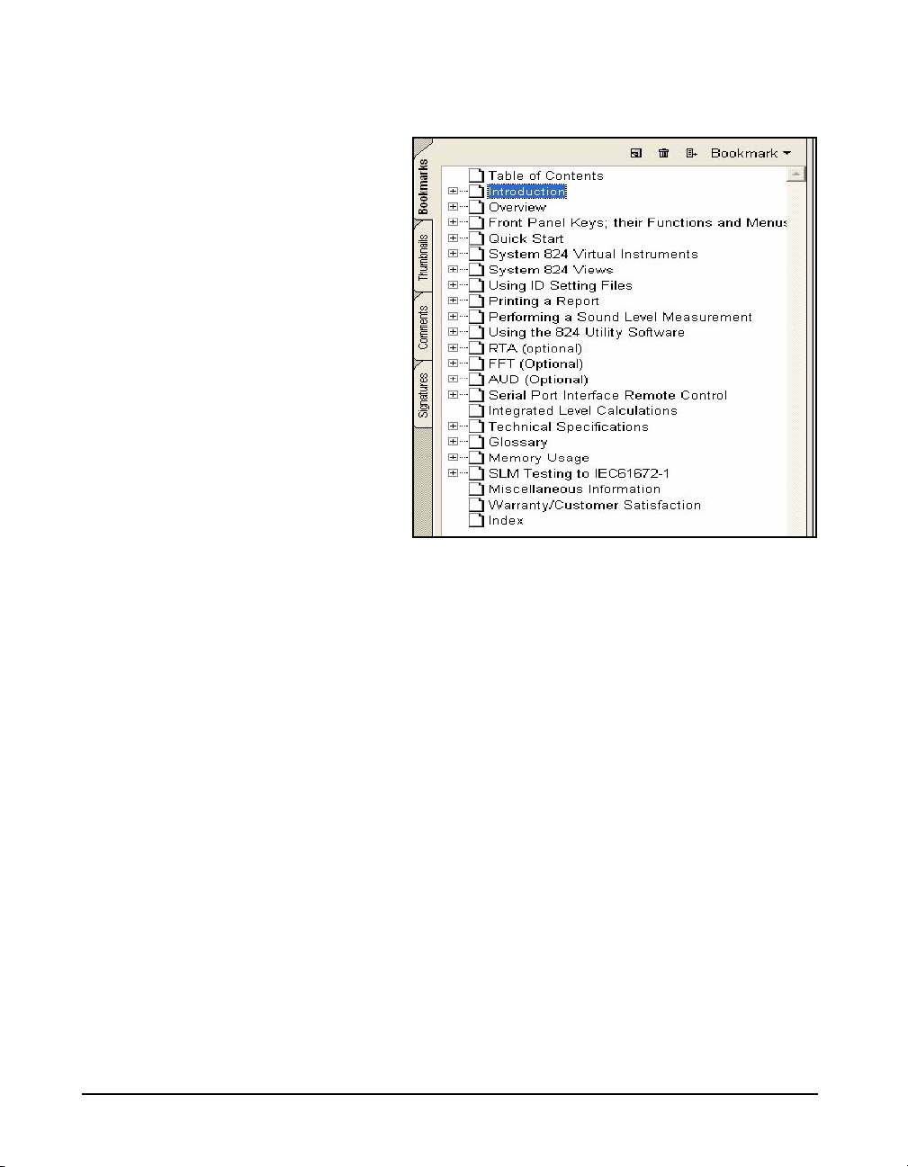
screen labeled Bookmarks. These will appear as shown
below.
In the unexpanded view, bookmarks lists the names and page
numbers of chapters and appendixes in order of appearance,
as well as the Table of Contents and the Index.
Closing Bookmarks
To close bookmarks, simply left click the tab once more.
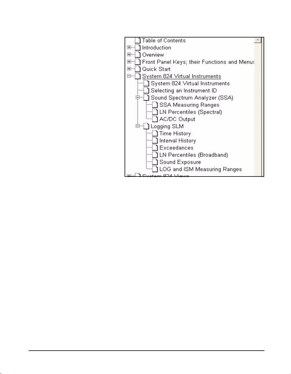
Expanding Bookmarks
For any entry, if there is a + within the rectangle to the left,
there are sub entries which can be displayed upon expanding
the tree by clicking the rectangle. For example, clicking the
+ to the left of any chapter will expand it into major
headings and, by clicking all the + symbols, the complete
tree for that chapter will be shown. In the following figure
we can see the entry System 824 Virtual Instruments
completely expanded.
1-4 824 Reference Manual 9/29/09
Page 25
Click to Display Page
Return to Previous View
Links
Click to Display Page
Left click on any text field (Chapter name, Appendix name,
Table of Contents, Index, or any sub heading) and the page
displayed on the right will jump to the page associated with
that text field.
To return to the page which was displayed previous to
clicking on a bookmark text line, right click on the display
page, then left click on “Go to Previous View”.
The Table of Contents and the Index have a page number
associated with each item. For the Table of Contents, left
click on the text line and that page will be displayed. For the
Index, left click on the page number itself to display the
page associated with that entry. To return to the previous
display, follow the procedure described in "Return to
9/29/09 Introduction 1-5
Page 26

About This Chapter
Press the v key
Detector [Slow]
Formatting
Previous View" on page 1-5
This introductory chapter covers the following topics:
• Formatting Conventions: Provides an explanation of
the fonts and other formatting conventions used in this
manual.
• Features: Gives an overview of the System 824 keypad,
functions and measurement capabilities.
• Getting Started: Provides instructions for unpacking,
inspecting and initially assembling the System 824.
This manual uses the following format conventions:
In step-by-step directions, the process (what you do) is
shown in the right column, and the rationale (why you do it)
with other cautions and comments are shown in the left
column.
1-6 824 Reference Manual 9/29/09
Keys to press on the LxT are shown with the icon
representing the appropriate key. For example:
Items that appear in various on-screen menus (such as
settings) are shown in bold and italicized style. For example:
Page 27

Features
Hardware Features:
The Larson Davis System 824 has the following features:
• Large backlit bitmapped graphic display
• Soft rubber backlit keys
• Pop-up menus with scroll bars
• Pick and choose setup...just click and run!
• File management system (stores multiple measurements)
• Multiple Instruments
SSA: Sound Spectrum Analyzer combining a
sound level meter and real-time spectrum analyzer
(optional)
LOG: Logging SLM (optional)
ISM: Integrating SLM (standard)
RTA: Adds high speed spectral data gathering
(optional)
FFT: Adds Fast Fourier Analysis to the 824
(optional)
AUD: Gives the 824 the ability to certify
audiometers; used in conjunction with the AUDit
software (optional)
TAL: Measures tonality according to DIN 45681
and appraisal of low frequencies according to DIN
45680 (optional)
• Type 1 precision integrating sound level meter: satisfies
IEC61672-1 (tested with 377B41 microphone only), IEC
60651-1993, IEC 60804-1993, and ANSI S1.4 1985)
9/29/09 Introduction 1-7
Page 28

• Simultaneous measurement of sound pressure level using
Fast, Slow, Impulse, Peak, and Leq detectors with A, C,
and Flat weighting (SSA, ISM, LOG, and TAL
instruments)
• Exceptionally large dynamic range (> 93 dB for SSA and
> 115 dB for ISM and LOG)
• Digital filters with real-time rate to 20 kHz satisfying
IEC 1260-1995 Class 1 and ANSI S1.11-1986 Type 1-D
meeting linearity specifications over a range of 85dB:
- 1/1 octave, 16 Hz to 16 kHz (11 filters)
- 1/3 octave, 12.5 Hz to 20 kHz (33 filters)
• Automatic logging of sound level parameters including
Interval data, L
statistics, noise event detection using
n
exceedance history and exceedance time history (LOG
only)
The windspeed (tacho) and wind
direction (throttle position) feature
requires the firmware option 824WND, not included with standard
System 824 configurations.
• Measurement of windspeed (tacho) and wind direction
(throttle position) using external weather transducers
with inclusion of data in Views and Data Displays for
SSA and LOG instruments.
• Real-time 1/3 octave spectrum analysis with rapid
spectrum vs. time autostorage and triggering for sound
decay measurement (RTA)
• Simultaneous operation of sound level meter with
independent frequency and 1/3 octave analyzer function
weighting (SSA)
• Advanced time history feature allows you to store up to
38 different parameters including spectral data with each
time history sample
• Narrow band real-time frequency analysis with 400-line
FFT and Hanning, Flat-Top or Rectangular window (FFT
Mode)
• Standard memory (2 MB) sufficient to store one of the
following:
- 30,000 point 1/3 octave SSA Leq time history
- 20,000 intervals with 1/3 octave Leq spectrum
1-8 824 Reference Manual 9/29/09
Page 29

- 12,300 SSA intervals with Leq & Max 1/3
octave spectra
- 60,000 LOG intervals without Ln
- 35,000 LOG intervals with Ln
- 1,000,000 point time history
- 70,000 RTA 1/1 octave spectra
- 28,000 RTA 1/3 octave spectra
- 2400 FFT 400 line snapshots
• AC/DC output, unweighted, with gain to 50 dB and
attenuation to -20 dB
• Flash memory for in-field firmware upgrades
• Multi-tasking processor: provides simultaneous
measuring, viewing, transferring and printing of data
• RS-422 (RS-232 compatible) interface:
Serial bit rate to 115 kbps
• Direct report printouts
•Windows
TM
-based software included for setup, control,
and high speed data downloading and translation to
ASCII format
9/29/09 Introduction 1-9
Page 30
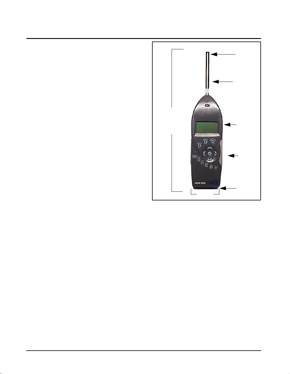
System 824 Components
Condenser
LCD Display
Keypad
Connectors
Microphone
38 cm
(15”)
9 cm
(3.5”)
Preamplifier
Figure 1-1 The System 824 is a convenient hand-held sound
level meter with a simple user interface.
The standard System 824 shown in Figure 1-1 includes the
following:
• 1/2” diameter condenser microphone
• Backlit graphic 64 x 128 pixel LCD display
• 14-key soft rubber backlit keypad
• AC/DC output, control, serial, and external power
connectors (shown in figure Figure 1-2)
• True “hand held” instrument with “sure grip” pads
1-10 824 Reference Manual 9/29/09
Page 31

Figure 1-2 The System 824 has a series of connectors located at
Control Connector
AC/DC Output Connector
External DC Power Connector
Serial Interface Connector
12
3
4
5
6
7
8
9
Logic Output
Wind Direction Input
Wind Direc Power
Ground
Windspeed
Logic In
Cal Check
Heater Cntrl
Ext Power
the bottom of the device consisting of an AC and DC output
connector, control connector, serial interface connector, and
external DC power connector.
The following is a layout of the control connector, which is
used to control external devices and receive external wind
and control information:
9/29/09 Introduction 1-11
Figure 1-3
9 pin mini DIN control connector; solder view
1 - Ground
2 - Logic output (0 to + 5 volts, active high, through 1 k)
3 - Logic input (0 to + 5 volts, active high, 100 k
load)
4 - Wind speed input (.05 to 10 Vdc peak to peak, 10 k
load)
5 - Wind direction A:D input (0 to 2.5 Vdc, 100 k
load))
6 - Wind direction power (+5 Vdc through 250 )
Page 32

7 - Calibration control output (0 to +5 volts, active high, 10
12
3
4
5
6
7
8
k)
8 - Heater control output (open drain, +40 Vdc Max, 100
mA Max)
9 - External power input/output (+8 to +15 Vdc)
The serial connector is used for computer, printer and
modem communications:
Both outputs have a 600 ohm series
resistance.
Figure 1-4
(AppleTalk
The serial connector is an 8 pin mini DIN connector
TM
compatible pinout).
1 - Flow control output (RS-232C levels)
2 - Flow control input (RS-232C levels)
3 - Transmit data negative output (RS-232C levels)
4 - Ground
5 - Receive data negative input (RS-422)
6 - Transmit data positive output (RS-422)
7 - Control input (RS-232C levels)
8 - Receive data positive input (RS-422)
The AC/DC output connector is used to output the signal
from the System 824 microphone to external devices such as
DAT recorders, real-time analyzers, other sound/vibration
measurement equipment, voltmeters, chart recorders, etc.
1-12 824 Reference Manual 9/29/09
Page 33
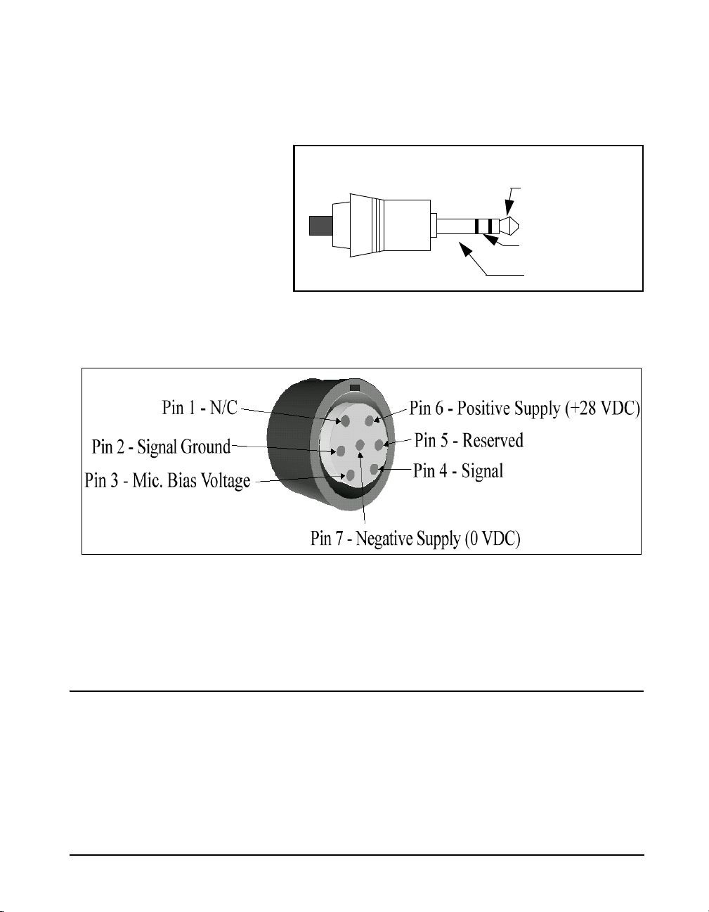
NOTE: See the section "AC/DC Output"
DC Output
AC Output (Tip)
Ground (-)
(+)(Ring)
on page 6-5 for more details concerning
the AC/DC outputs.
Figure 1-5 AC/DC output connector
Preamplifier Input Connector
The preamplifier input connector accepts the PRM902
preamp.
System Diagram
Figure 1-6, illustrates the acoustic-to-digital signal path in
the System 824. As you can see, incoming sound is first
converted to an electrical signal by the microphone. This
electrical signal is amplified, filtered and then sampled by an
9/29/09 Introduction 1-13
analog-to-digital converter (ADC). The processor then
Page 34

Getting Started
Unpacking and Inspection
calculates all of the desired data based on the sampled data
(sample rate of 48-51.2 kHz).
This section outlines the steps to unpack the System 824.
The following topics are covered:
• Unpacking and Inspection
• Accessories and Optional Equipment
• Connecting Internal or External Power
• Environmental Considerations
You will then be ready to use the System 824 for actual
measurements.
Your System 824 has been shipped in protective packaging.
Please verify the package contains the items listed below.
Retain the packaging for safe shipment for calibration
service. Report any damage or shortage immediately to
Larson Davis, Inc. at (801) 375-0177.
If you have not already done so, please record the purchase
date, the model and serial numbers for your instrument, preamplifier and microphone in the spaces provided on the
copyright page near the beginning of this manual. You will
find the instrument’s Model/Serial numbers printed on the
label on the instrument’s back panel. The microphone’s
Model/Serial numbers are located on the inside ring of the
microphone. The pre-amplifier’s Model/Serial numbers are
engraved the outside surface. You may be asked to provide
this information during any future communications with
Larson Davis, Inc.
1-14 824 Reference Manual 9/29/09
Page 35
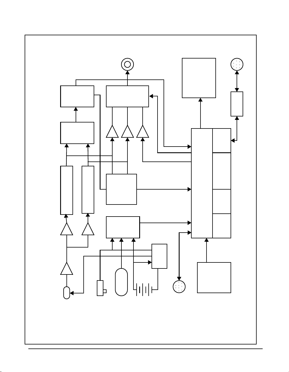
mic
Preamplifier
0-50 dB gain
Flat, A-Wt, C-Wt
or 10 Hz High Pass
Flat, A-Wt, C-Wt
or 10 Hz High Pass
Analog to
Digital
Converter
Digital
Signal
Processor
AC/DC out
Mux
Frequency
Detection
Analog to
Digital
Converter
External
Power
Battery
Temperature
Sensor
Power
Supply
Control I/O
Microprocessor
RAM
1/2 to 2 MB
Flash ROM
Real-time clock
and calendar
Serial I/O
Key Pad
Graphic
Liquid Crystal
Display (LCD)
128x64 with
backlight
RS-422/232
transceiver
DC out
AC out
AC out
0-50 dB gain
824 System diagram
Serial I/O
Figdfdsafdsa
Sysjklsfdakjl;fasdjl;kasdflj;ksdfal;jkklj;kl
Figure 1-6 System Diagram
9/29/09 Introduction 1-15
Page 36

Comments concerning the Digital Signal Processor
Although the System 824 does have analog Flat, A-weight,
C-weight and 10 Hz high pass filters ahead of the Analog to
Digital Convertor, most of the measurements use digital
weighting filters created by the Digital Signal Processor.
The Digital Signal Processor implements the following in
order to provide measured data for a wide range of
weightings, filters and detectors.
• A, C and Flat broadband filters
If the System 824 is not being used
• Real-time FFT and 1/1 and 1/3 octave band filters
for long periods of time (1 month or
more), it is recommended that the
batteries be removed to avoid
damage to the instrument.
• Slow, Fast and Leq true RMS detectors
• Impulse and Peak detectors
Accessories and Optional Equipment
The System 824, 824S, 824L and 824A can be purchased
with or without a microphone; they all include the Model
PRM902 microphone preamplifier.
NOTE: Two Terminal assemblies are
provided though only one is used. The
second one is a spare. To avoid losing
them, keep them in the accessory kit in
the carrying case provided.
The System 824, 824L and 824A are delivered with the
following standard accessories (824-ACC Pack):
• Battery pack, NiMH, 3.6 V, 1.2 AH (BAT010)
• Reference Manual (I824.01)
• Serial cable, DB9S to DIN08 (CBL006)
• AC/DC output cable, 1/8" mini phone plug to dual phono
or BNC (CBL042)
• Universal AC power adapter. (90 to 264 Vac, 50 to 60
Hz, 12 volt output) (PSA027)
• Alkaline battery terminal assembly (AM814.06)
individual alkaline batteries when NiMH battery pack is not
used.
1-16 824 Reference Manual 9/29/09
Connects
Page 37

• Hard case 15”x19”x7” (CCS001) with foam insert
(0860.0077)
•Windows
TM
utility software (SWW_824_UTIL)
• 10 foot microphone extension cable (EXA010)
• 3 1/2” diameter windscreen (WS001)
The 824S is delivered with the following standard
accessories (824S Pack):
• 3 x 1.5 V “AA” alkaline batteries
• Alkaline battery terminal assembly (AM814.06)
individual alkaline batteries when NiMH battery pack is not
used.
Connects
• 3 1/2” diameter windscreen (WS001)
The following optional equipment is also available:
• CAL200 Sound Level Calibrator, 1000 Hz @ 94 or 114
dB (IEC 942-1988 Class 1)
• CAL250 Sound Level Calibrator, 250 Hz @ 114 dB (IEC
942-1988 Class 1)
• Microphone extension cables are available in 1.5, 6, 10,
20, 25, 35, 50, 66, 100, and 200 foot lengths or custom
lengths up to 328 feet.
• Direct BNC microphone input adapter (ADP005)
• External Battery Charger (PSA024) (Used to quick
charge the BAT010)
• Accelerometer preamplifier for ICP accelerometers
(PRA951-4 provides 4 mA DC current)
9/29/09 Introduction 1-17
Page 38
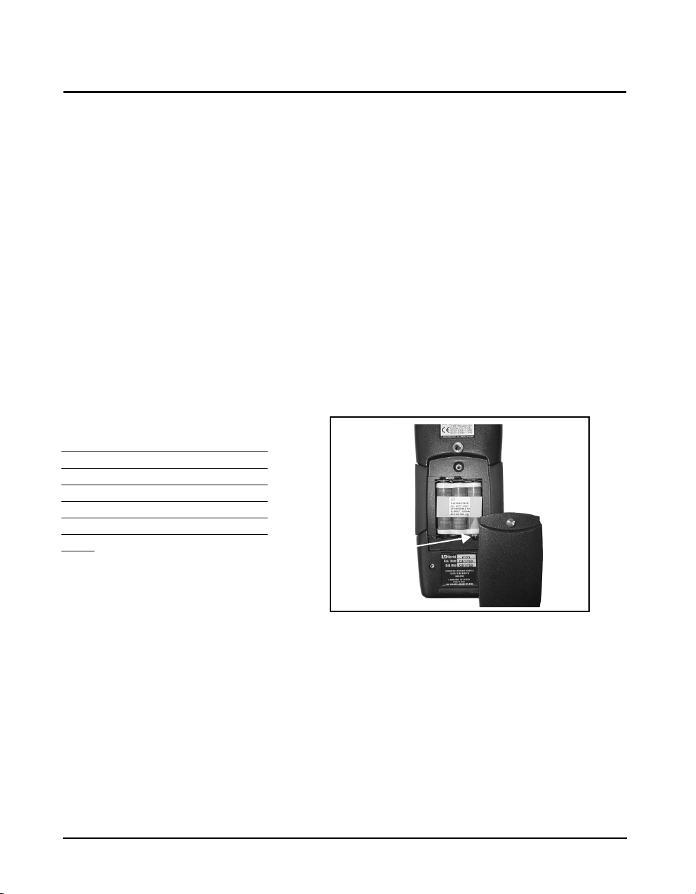
Connecting Internal or External Power
Positive
Ter mi na l
The 824 is shipped with a NiMH
battery pack installed.
Using the NiMH Battery Pack To use a NiMH battery pack (BAT010) with the System 824,
For additional battery information,
refer to the section
page 3-3. For detailed information
on charging NiMH batteries, refer to
the section "Power Settings" on page
3-6
If power is supplied with the AC
Power adapter, the NiMH or alkaline
batteries do not require removal and
will power the unit if the AC power
adapter fails. Without AC power or
batteries installed, memory loss will
occur.
vPower key on
The System 824 can be powered using a 3.6 V NiMH
battery pack, individual alkaline or NiMH cells, or an AC
power supply adapter. For specifications on operating time
under battery power, see “Battery Operating Time (full
capacity, continuous operation, reference environmental
conditions, individual cells may vary in performance)” on
page -C-6. Below we will discuss how to install and use
each.
unscrew the battery cover at the back of the System 824 by
hand or using a flat blade screwdriver. If individual cell
batteries were previously used, remove the Terminal
Assembly (Figure 1-8). Insert the battery pack so that the
positive terminal is oriented down and to the right, as shown
in Figure 1-7.
Figure 1-7
pack installed. (Note location of positive terminal.)
1-18 824 Reference Manual 9/29/09
Battery compartment and cover with NiMH battery
Page 39

Using Alkaline Batteries or Individual NiMH rechargable cells.
Use Duracell MN 1500 (1.5 volt,
2,850 mAH) alkaline battery or
equivalent. You may also use the
Duracell Ultra
Titanium
which may provide up to 40% more
run time.
Note: It is important to set the
battery type to NiMH if individual
NiMH cells are being used to power
the instrument; otherwise there will
not be sufficient battery reserve to
preserve the memory once the
batteries are drained. Also, the
proper setting is important in terms
of the ability of the instrument to
accurately estimate the remaining
battery life
or Energizer
next generation batteries
To use alkaline batteries or individual NiMH cells, remove
the battery cover, and if installed, remove depleted batteries
(or NiMH battery pack). If not already installed, insert a
battery Terminal Assembly (AM814.06) so that it is
positioned as shown in Figure 1-8. Insert three AA batteries
so that polarities match those indicated in the battery
compartment and secure the battery cover.
Indicate the battery type being used as follows;
Step 1 Press the
Step 2 Press the
Step 3 Use the
Step 4 Press
Step 5 Press
appropriate battery type; alkaline or NiMH.
Step 6 Press the
followed by the
menu.
If the rechargeable LD BAT010 battery pack is used, the
setting is overridden and assumed to be NiMH. The 824 will
automatically detect the presence of the pack, so the setting
can be left to what would most likely be used if individual
cells were to be used instead of the battery pack.
v key.
c key
dkey to highlight “Type”
ckey to activate the “Battery Type” menu.
dor ukeys to select the
c key to enter the selection,
lkey to close the Power
Note: The System 824’s “smart”
charging system is designed to detect
alkaline batteries and prevents
accidental charging.
9/29/09 Introduction 1-19
If alkaline cells are installed but erroneously declared as
NiMH, the charger will start for several seconds, then will
detect that they are not NiMH. Charging will be terminated
and the battery type changed to alkaline. This safety
measure will prevent primary cells from being charged and
damaging the instrument due to leakage or explosion.
Nevertheless, it is inadvisable to ever attempt to charge
primary or non-rechargeable batteries.
Rechargable individual NiMH cells can also be charged in
an external rapid charger.
Page 40
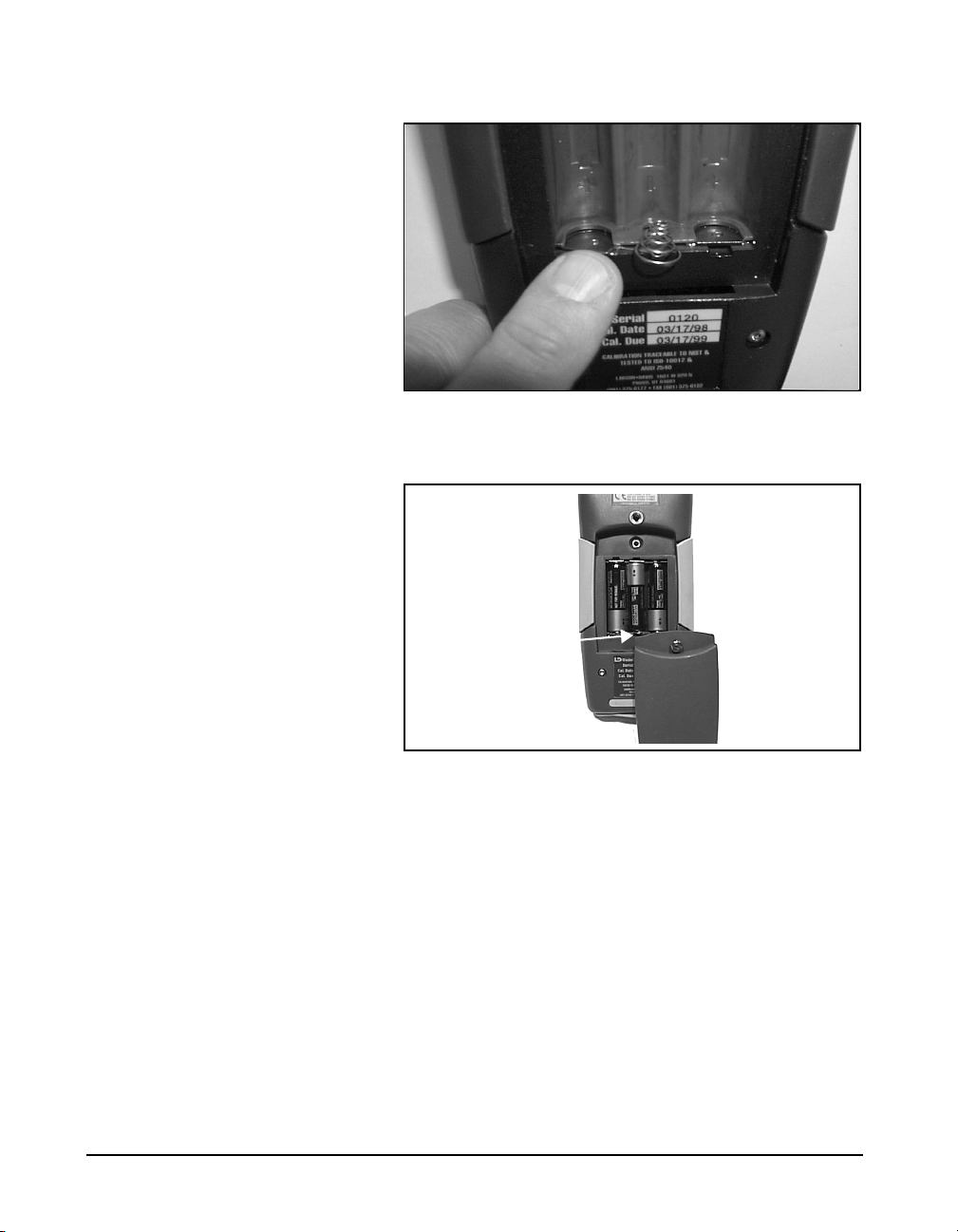
Figure 1-8 Battery Terminal Assembly orientation.
Ter min al
Assembly
Figure 1-9 Battery cover and compartment with alkaline
batteries and Terminal Assembly installed. (Note location of
Terminal Assembly.)
Using the AC Power Adapter You may use an external power source via the external
power connector using the provided power adapter. The
System 824 accepts 6 to 15 VDC and is internally fused at
0.5 A.
1-20 824 Reference Manual 9/29/09
Page 41

CHAPTER
Overview
2
This Chapter presents a general overview of the structure of
the Model 824, an example of selecting a Setup or Instrument Definition (ID), performing a measurement and storing
the data. Subsequent chapters will deal specifically with
these steps in a more structured manner.
System 824 Setups or Instrument Definitions
The power and flexibility of the System 824 gives you a
variety of measurement possibilities. The System 824 has a
number of distinct setups or Instrument Definitions (ID)
from which you can select the one best suited for a particular
application. You can, of course, modify any instrument
definition for another application and add it to the existing
list of instrument definitions.
The System 824 was designed to be
upgraded with new instrument
capabilities as they are made
available. Please contact
Larson•Davis for information on the
latest available upgrades.
9/29/09 Overview 2-1
An ID name consists of an eight character name followed by
a three character extension called the Instrument Type. Some
IDs presently available are: SLM&RTA.SSA, SLM.ISM and
Logging.LOG.
The complete ID consists of its name and an instrument
setup based on one of the available Instrument Types. There
are a number of factory supplied setups available for use by
the user. In order to create a new setup, modify an existing
ID and store it under a different name as a new setup. The
Instrument Type will remain the same as that of the ID used
to create it. Thus, a new setup created for the measurement
of environmental noise by modifying the Logging.LOG ID
might become ENV.LOG.
Page 42

Instrument Definition (ID) Types
Instrument Definition (ID)
SLM&RTA (SSA) Logging (LOG) SLM (ISM)
SLM Range (dBA) 80 105 105
Real-time Spectrum
Analysis
Manual Data Storage Yes Yes Yes
Back Erase Yes No Yes
Automatic Data
Logging
Major Applications Noise Reduction Sound
1/1 and 1/3 octave
bandwidths
Time History
Intervals (sound level
and spectral data)
Power
No No
Time History
Exceedance Events
Intervals (sound level)
Noise Monitoring Noise
Workplace
Write Protect, Delete, Write Enable IDs
After an ID has been created, it can be protected (or locked),
or deleted if necessary. This is described in detail in the
section "Write Protect, Delete, Write Enable IDs" on page 3-
17.
SLM&RTA (SSA)
No
Point & Shoot
Law Enforcement
Workplace Noise
The SSA ID performs simultaneous sound level
measurements and real-time spectrum analysis using 1/1 or
1/3 octave bandwidths. The Instrument Type designation
“SSA” represents Sound Spectrum Analyzer. Sound levels
during the measurement period are displayed and can be
stored for later recall. In addition to a live spectrum display,
the System 824 can display an equivalent level (L
spectrum, a minimum bin by bin level (L
maximum level (L
2-2 824 Reference Manual 9/29/09
) spectrum, which is the spectrum time
max
) spectrum and a
min
eq
)
Page 43

coincident with the maximum value of the sound pressure
level during the measurement period.
A back erase function allows the removal of up to the last 30
seconds (in one second steps) of data when a disruptive
noise occurs.
The 824 also provides an automatic measurement and
logging feature which provides the sound level parameters
L
, SEL, L
eq
max
, L
min
, L
and the Leq and Max or Min
Peak
spectra data at regular user-defined time intervals. Due to the
complex digital processing necessary to perform
simultaneous sound level measurements and spectrum
analysis, the measurement range in this mode is reduced to
80 dBA.
The design of the System 824 permits the simultaneous
measurement of the following sound level parameters, a
feature we call “Any Data”:
Live SPL Lmax Lmin
Leq Peak
Slow Fast Impl Slow Fast Impl Slow Fast Impl
A
C
Flat
99999999999
99999999999
99999999999
Note: The detector used to create
Leq is a pure integrating true RMS
detector which integrates the energy
over a specific period of time. It may
be as short as 1/32 second, in a time
history which may be as long as 24
hours. As a result, it does not include
decay artifacts of older instruments
that integrate the output of the
SLOW or FAST detectors.
Detectors Detectors Detectors
Peak Sound Pressure Level (L
) with A, C and Flat
peak
weighting.
Equivalent Continuous Sound Pressure Level (L
A, C and Flat weighting. A time history record can be
enabled to capture samples at periods as short as 1/8th of a
second.
Spectral Analysis with Time History Record allows you to
record spectral data along with the 33 sound level
parameters mentioned above.
) with
eq
9/29/09 Overview 2-3
Page 44

An interval history which includes 6 Ln values (6 values
with 0.1 dB resolution, based on user-selected percentages
with 0.01% resolution).
For Takt users, as a no-cost option, the following additional
parameters are provided:
Taktmaximal with the following combinations of frequency
weighting and time weighting:
Taktmaximal 3 Taktmaximal 5
Slow Fast Slow Fast
SLM (ISM)
Logging (LOG)
A
C
Flat
9999
9999
9999
The SLM (ISM) is the simplest to operate, providing the
functions of a “point-and-shoot” sound level meter with
manual data storage. The SLM (ISM) Instrument ID
measures the same thirty-three sound level parameters as the
SLM&RTA (SSA) ID, but it does not provide frequency
spectrum measurement capability. However, since less
digital processing is required, the measurement linearity
range is 105 dBA, permitting the use of a single range for all
measurements.
This ID is designed particularly for noise monitoring
applications and provides extensive automatic data storage
features. The Instrument Type designation, LOG, represents
a Logging sound level meter. Like the SLM (ISM) ID, the
measurement range is 105 dBA and does not provide
frequency spectrum measurement capability. Up to thirty-six
measured sound level parameters can be stored as a Time
History record at rates as rapid as 32 samples per second.
2-4 824 Reference Manual 9/29/09
Page 45

The following parameters can be logged at user-selectable
time intervals between 1 second and 99 hours (hh:mm:ss)
•L
max
, L
, SEL, and Leq (q=3) or Time Weighted Aver-
min
age (q=4, 5, or 6) levels for a selected detector (Slow,
Fast, or Impulse) and a selected frequency weighting (A,
C, or Flat)
•L
level corresponding to the frequency weighting
peak
selected for L
(see charts above) and a second L
eq
peak
level corresponding to one of the two alternative choices
of frequency weighting.
•L
(6 values with 0.1 dB resolution, based on user-
n
selected percentages with 0.01% resolution)
• Date, time and duration of interval
• Six user-selected values of L
can be measured and
n
stored as part of the automatic interval data storage function.
• A special feature is the automatic measurement and logging of data associated with noise exceedance events that
are triggered by the sound level exceeding a user-defined
threshold. L
, SEL and L
eq
for each event are logged
Peak
along with a Time History of the sound level during each
event.
• Daily history and community noise metrics.
9/29/09 Overview 2-5
Page 46

Selecting a Measurement Setup
The simplest way to setup the instrument is to select the ID
which most closely meets the requirements of the
measurement to be made and then modify it to meet your
specific needs. The instrument is delivered with a number of
permanent setups. The standard ID delivered with the
instrument is ISM. The optional IDs available are: SSA,
LOG, RTA, FFT, AUD, and TAL. If the options for the SSA,
LOG, RTA, FFT, AUD, or TAL have not been purchased,
they can be evaluated in a demo mode.
Restrictions of demo IDs:
• Cannot print reports
• Cannot store data
• Cannot perform any I/O commands
• Only 20 demos are permitted
• Memory must be purged prior to activating these IDs
The following is an overview of how to select a
measurement setup.
Step 1 To display the available instrument setups, press
the
S Setup key.
Note that each of the permanent
setups has a letter “p” to the left of
the setup name, indicating that it
cannot be modified or deleted. It can
be saved under another name and
then modified.
At any time, one of the available setups will be the
active setup. The name of this setup will be at the
top of the list below the Edit Setting message.
Pressing the
menu item is highlighted initiates the modification
procedure.
2-6 824 Reference Manual 9/29/09
c key while the “Edit Settings”
Page 47

After selecting a measurement setup,
press the
measurement.
s key to initiate the
Step 2 To select the desired setup, scroll through the
setup list with the u and d keys until the
item is highlighted, then press
It will be shown later how the Setup Menu can be utilized to
modify one of the permanent setups to meet your
requirements. The 824 Utility software is also very useful
for selecting and modifying setups.
Performing a Measurement; SLM&RTA (SSA)
Without getting into the fine details of operating the System
824, let’s just press some keys and see what it can measure
and display.
Step 1 Let’s look at the SLM&RTA (SSA) ID Access the
Setup Menu by pressing
u keys to highlight the SLM&RTA ID, as
shown below:
S and use the dand
c.
Step 1 With SLM&RTA highlighted, press
as the current ID.
Step 2 Press the RUN/STOP key
ment and obtain a display resembling the following:
You can see from the top line that the
meter is in the SLM+RTA mode, and
the bold SLM indicates that it is the
SLM display or VIEW as we refer to
it when using the Model 824.
9/29/09 Overview 2-7
s to begin a measure-
c to select it
Page 48

The large numerals represent the SPL measurement taken
with the Slow detector and the A-weighting. In the lower left
is an indication of the Leq value and the elapsed time of the
measurement for which the Leq value is calculated. The
graph being traced across the display is a time history of the
SPL value.
Stop, Pause and Back Erase Functions
While taking a measurement you can stop, pause, and back
erase.
Stopping and Starting Measurements
Pausing Measurements To pause the measurement press the
Back Erasing Should an unwanted sound occur during the measurement,
To stop the measurement, press the
pressing
s.
s key. Restart by
p PAUS E key. To
continue the measurement press the
While paused, the
cursor across the time history and display the SPL and
secondary parameters as measured at any particular time
during the measurement period.
such as a door slam, you can pause the instrument, cursor to
the left with the
event, and press the
measurement from that point, erasing the data to the right of
the cursor. This is the Back Erase feature as indicated on the
display when the
landrkeys can be used to move a
lkey to a time prior to the unwanted
p key once more to recommence the
p key had been initially pressed.
p key a second time.
Changing the detector of the displayed SPL value
You can change the parameters being displayed in the View
window while a measurement is in progress without going to
the Setup menu.
2-8 824 Reference Manual 9/29/09
Page 49

Step 1 To change to the detector type, use theuor d
keys to highlight the Slow detector, as shown
below:
Step 2 To scroll through the optional detectors, press the
rorlarrow keys. This will display the SPL
corresponding to the Fast and Impulse detectors.
Go back to the Slow detector and press the check
c key or wait several seconds until the highlight
disappears.
Changing the frequency weighting of the displayed SPL value
Step 1 To select the frequency weighting parameter, press
the
uord keys to highlight the A-weighting
as shown:
Step 2 Use the
weighted or Flat-weighted SPL corresponding to
the Slow detector.
9/29/09 Overview 2-9
rorlarrow keys to display the C-
Page 50
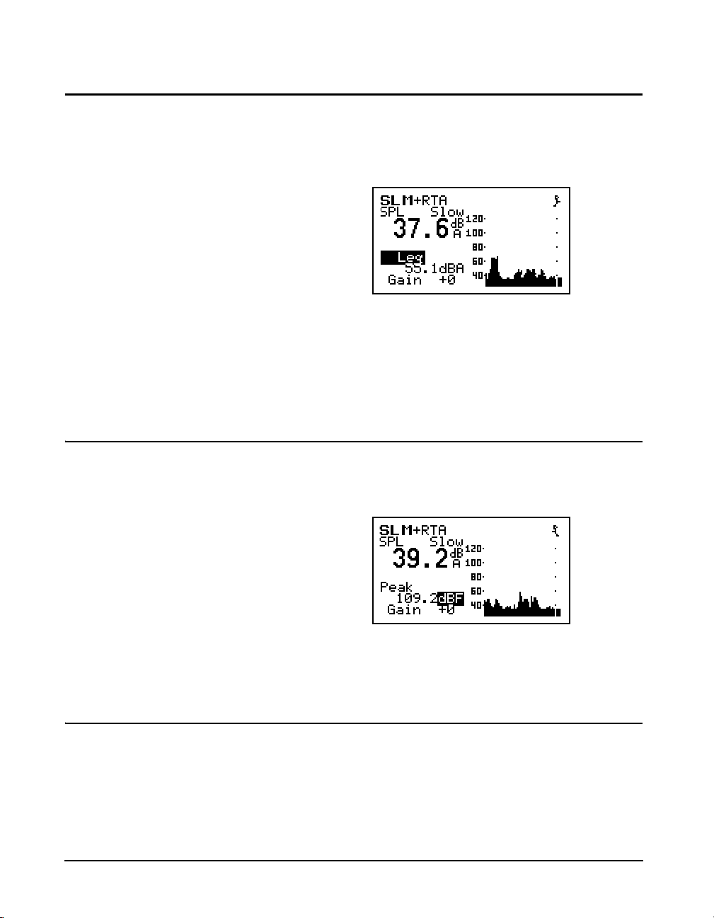
Changing the displayed secondary parameter
Step 1 To select the secondary parameter to be displayed
(Leq in this example), use the
highlight the Leq label.
uordkeys to
Step 2 Press the
ues of A-weighted SEL, Lmin, Lmax, Lpeak values. Select “Peak” and press the check
rorlarrow keys to display the val-
Changing the frequency weighting of the displayed Lpeak value
Step 1 With the Peak label selected, press the uor
dkeys to highlight the Peak weighting.
Use the
weighted Lpeak values.
rorlarrow keys to display the A, C or Flat
Changing the amplitude range, or input Gain
c key.
When using the SSA ID, as in this example, the
measurement range is 80 dB, unlike the ISM and LOG IDs
for which it is 105 dB. In order to optimize a particular
measurement, provisions have been made to select a value
of input gain directly from the graphic display. The gain can
2-10 824 Reference Manual 9/29/09
Page 51
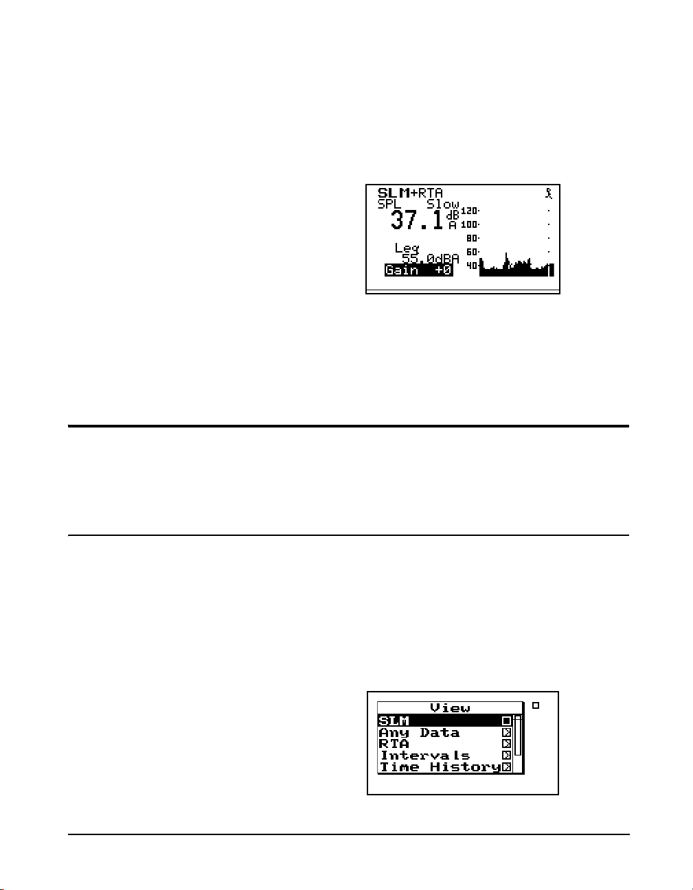
also be changed from the Setup Menu, as described later in
this manual or it can be changed here.
The gain shifts the dynamic range up
or down. See page 5-3.
Views
Step 1 To change the gain, Use the
highlight the Gain, as shown below
.
Step 2 Use the
gain.
For each instrument type (e.g. ISM, LOG or SSA), a unique
set of data displays or VIEWS are available.
rorlarrow keys to change the input
uordkeys to
Selecting a VIEW
There are eight different VIEW choices available in the SSA
instrument.
Step 1 To display the set of available data presentations,
or VIEWS, press the
and
u keys to scroll through the entire range of
choices).
9/29/09 Overview 2-11
V View key (use thed
Page 52
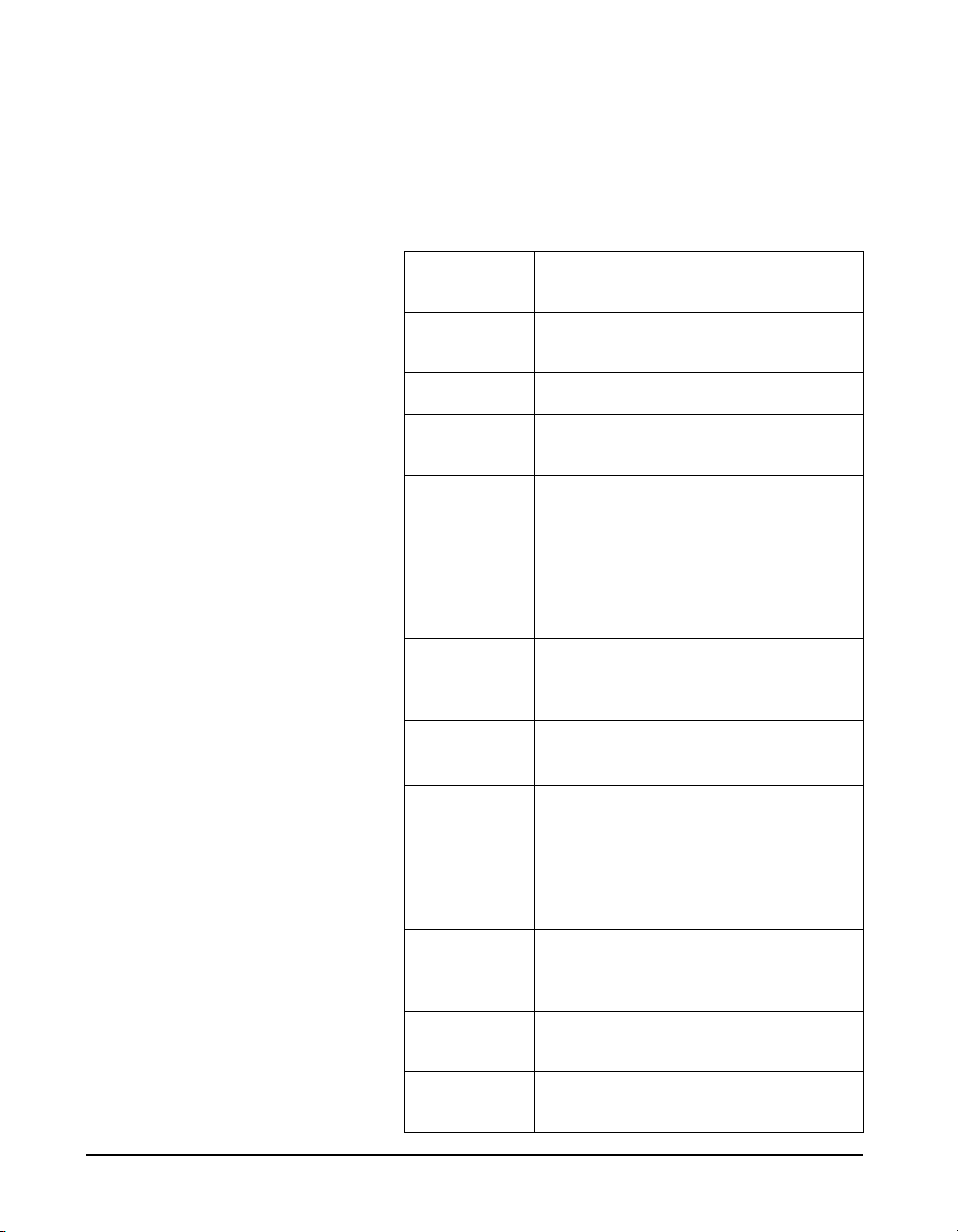
The VIEW choices for the SSA instrument type are as
follows:
Use the upuand downdarrows
to select a menu item, right
to enter a submenu and left
rarrow
larrow
to exit a menu.
SLM
Any Data
RTA Live
RTA Leq
RTA Max
RTA Min
Intervals
Leq Spectrum
Max/Min
Spectra
Sound Level Meter parameters, graphic and
digital display
Tabular presentation of sound level meter
parameters
Live display of real-time frequency spectrum
Display of Leq spectrum over elapsed measurement period
Display of the live spectrum corresponding
to the maximum value of sound pressure
level occurring during the measurement
period.
The minimum level recorded for each frequency during the measurement.
Sound Level parameters measured and automatically stored at regular user-defined time
intervals.
Leq spectra measured and automatically
stored at the interval rate.
Instantaneous spectrum corresponding to the
maximum sound pressure level occurring
during each of the user-defined time intervals or the minimum level for each frequency as selected by the “Intv Spectrum”
setting.
Time History
Run Log
Ln Centiles
2-12 824 Reference Manual 9/29/09
Sound Level parameters and spectral data
measured and automatically stored at user
defined time periods.
Displays the start and stop times/dates of the
active measurement.
L1 - L99 displayed for the measurement
period.
Page 53

As part of this exercise, select each of these various VIEWs
and use the
different parameters are displayed within each function.
We have sought only to explain the general concept of the
VIEW function at this time. More detailed explanations are
provided later in Chapters 3 and 6.
Data Storage and Recall
When a measurement has been performed and the
instrument stopped, the measured data can be stored to nonvolatile memory before the instrument is reset or the setup
changed; otherwise the data will be lost. Attempting to
change the setup while there is measured data available will
cause the system to prompt you to store the data before
continuing.
dandukeys to see how a variety of
Storing Data Step 1 To store measurement data, press the
key. The following menu appears:
The “Recall Files” line only appears
if data has previously been stored.
Step 2 With the message “Store File” highlighted, press
the
c Check key to store the data.
Recalling Data Step 1 To recall stored data, highlight “Recall Files” and
press the
appears.
c Check key. The following screen
D DATA
9/29/09 Overview 2-13
Page 54
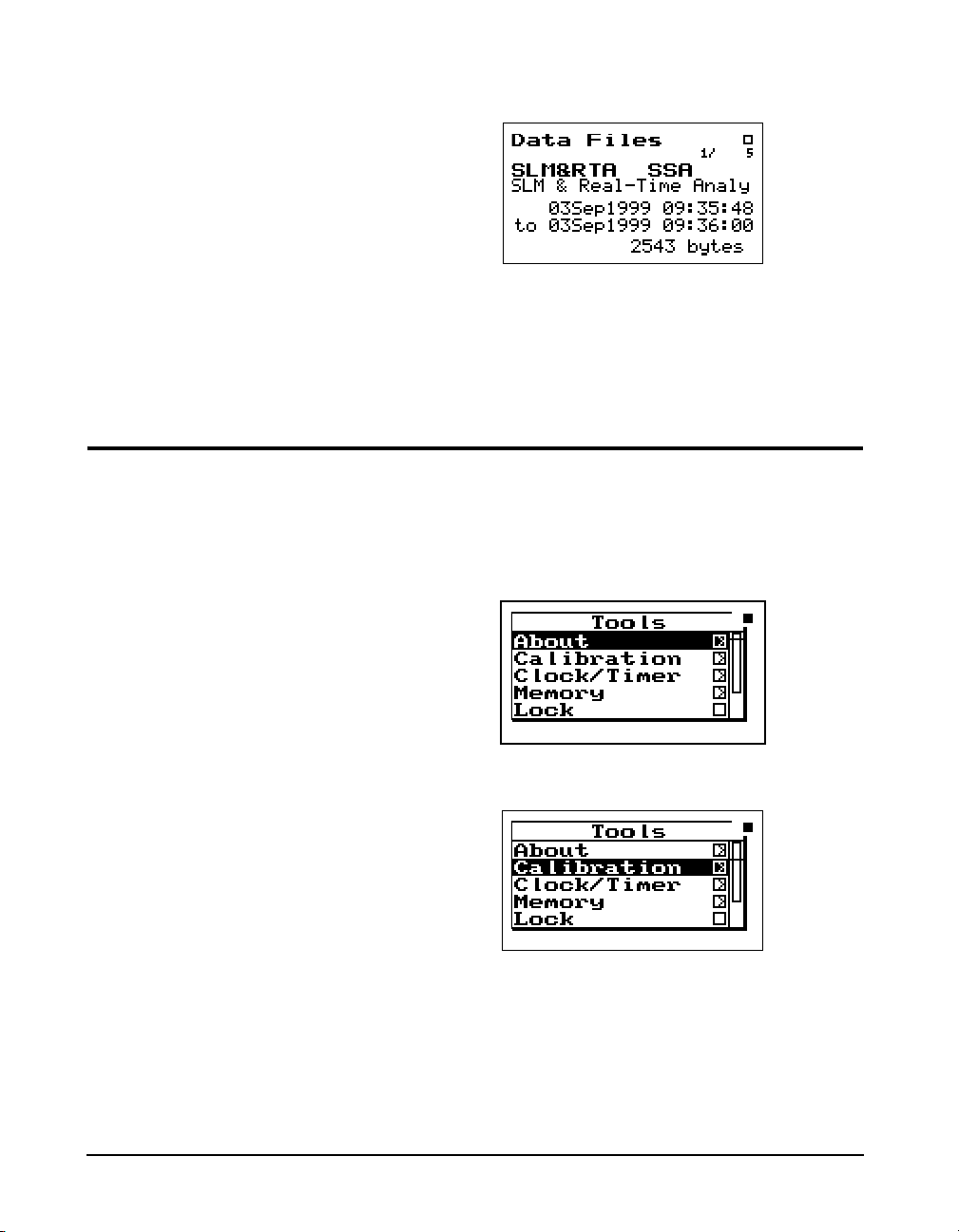
Calibration
Step 2 Press the up uand down darrow keys until
the desired file is indicated. Press the check
key, select “Recall” from the menu and press the
check
c key again.
c
Power off the instrument prior to
connecting a microphone or
preamplifier; the high voltage spike
created when connecting while the
instrument is on can damage
sensitive electronic components.
Calibration is one of the functions available from the Tools
Menu.
Step 1 Press the
Step 2 Press the
T TOOLS key.
dkey to highlight “Calibration”.
2-14 824 Reference Manual 9/29/09
Page 55
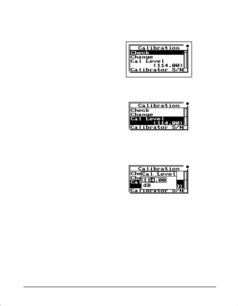
Step 3 To setup the calibration process, press therkey
to move into the Calibration Menu.
NOTE: The output level specified by the
calibrator manufacturer will be at
standard temperature and pressure. In
practice the level is a function of
temperature and static (barometric)
pressure, so a corrected level should be
used. Similarly, the sensitivity of the
microphone itself is a function of
temperature and static pressure. For
directions on compensating for
temperature and static pressure during
calibration, see "Correction of
Calibrator Output Level" on page 2-17.
Step 4 To set the calibration level, press the
d and
u keys to highlight “Cal Level”,
Step 5 To set the value of the sound level provided by the
calibrator, press the
Level window.
Step 6 Then use the
position) and the
its) to enter the proper level.
rkey. This displays the Cal
landrkeys (to move the cursor
uanddkeys (to change dig-
Step 7 To select the new calibration level press the
c
Check key.
9/29/09 Overview 2-15
Page 56
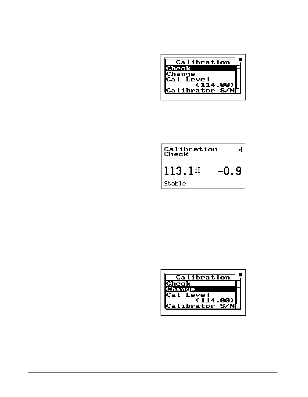
Step 8 To verify that the instrument is properly cali-
brated, use the
Step 9 Place the calibrator over the microphone, switch
the calibrator ON, and press
ibration Check process.
The display will show the measured level and the difference
from the calibrator level entered and the measured level as
shown.
ukey to highlight “Check”.
c to activate the cal-
Step 10 If the calibration is not reasonably close to the
level of the calibrator, the calibration can be
changed by choosing Change. Press
the
dkey to highlight “Change”.
Step 11 Switch the calibrator ON, and press
2-16 824 Reference Manual 9/29/09
c, use
c.
Page 57

Correction of Calibrator Output Level
The CAL200 provides a nominal pressure level of 94 dB or
114 dB. The exact levels are printed on the Larson Davis
calibration sheet that is delivered with the calibrator. The
free field level is -0.12 dB from either of these levels. If the
calibrator and instrument are near room temperature and
near sea level then no other corrections need to be made. If
the calibration sheet for the CAL200 indicates 113.98 dB for
it's level when set to 114 dB then set the Cal Level in the 824
to 113.86 dB.
When the microphone and instrument are at a temperature
other than near room temperature or static pressures not near
sea level, then corrections need to be added for the ambient
temperature and the prevailing static pressure. Check the
calibration data shipped from Larson Davis with the
CAL200 to get these corrections. The corrections can be
added to the level obtained in the previous paragraph to get
the actual level of the CAL200.
The 377B41 microphone's sensitivity varies with static
pressure. The coefficient of static pressure is -0.01 dB/kPa.
If the system is calibrated at 85 kPa for instance then it will
be 0.16 dB less sensitive at sea level. The 377B41 and 824
vary with temperature. The coefficient of temperature is
+0.012 dB/°C. If the system is calibrated at 25°C then it will
be 0.024 dB less sensitive at 23°C.
9/29/09 Overview 2-17
Page 58

2-18 824 Reference Manual 9/29/09
Page 59

CHAPTER
Front Panel Keys; Functions
3
and Menus
This chapter contains an overview of the functions which are
accessed through the System 824 keypad (see Figure 3-1
below):
Figure 3-1
The 14 keys on the System 824 keypad are organized into
these four sections: Power, Measurement, Navigation, and
Control. These keys are covered in the following order in
this chapter:
9/29/09 Front Panel Keys; Functions and Menus 3-1
System 824 Keypad.
Page 60

Power Key
v
POWER
Measurement Keys
Turns on / off the System 824; accesses battery power monitoring and LCD utilities,
and is used to close menus.
s
RUN/STOP
p
PA US E
R
RESET
Navigation Keys
u
....
r
l
.....d
ARROW
Begins and ends measurements.
Pauses readings while running, Previews
current SPL when stopped. Activates
Back Erase function.
Displays Reset options menu. (Current,
Overall, Options)
Used to move through System 824
menus, change settings, and scroll
through data displays. The lkey exits
menu’s.
c
SELECT
Control Keys
V
VIEW
D
DATA
3-2 824 Reference Manual 9/29/09
Selects highlighted menu items (like a
button on a mouse), concludes data entry
(like the Enter key on a PC keyboard)
and activates context specific menus
(called Check menus).
Displays View menu choices where you
can select which data to view.
Displays the Data Files menu. This
menu is used to store and recall Data
Files.
Page 61

S
SETUP
Displays the Setup menu. Allows you to
view and edit the settings for the active
instrument or recall a stored Instrument
Definition (ID).
NOTE: The reference information in this
chapter is organized according to functions, rather than by tasks (which can
use several functions).
v Power Key
T
TOOLS
P
PRINT
The functions and displays associated with the above keys
are described next. In addition, relevant reference material is
included for settings and options which may be available for
keys on the System 824 keypad.
The purpose of the POWER key v on the System 824 is to
turn the power on or off, close menus, and display the
remaining battery life. Once the System 824 is turned on,
pressing the
where you can change screen contrast, turn the backlight on
or off, and adjust power options. To turn the instrument off,
press and hold down the
release key. Release the
off.
Displays the Tools menu. Allows you to
change Calibration, Clock/Timer, Memory, Lock, Power Monitor, and Communication settings.
Displays the Print menu. Allows you to
change print settings, and to print data
reports and Snapshots.
v key again will activate a PWR display
v key until prompted to Please
v key and the instrument turns
This section discusses the following:
• Power-up the Instrument / Viewing PWR Display
• Power Settings
• Extra Notes on Power Conservation
9/29/09 Front Panel Keys; Functions and Menus 3-3
Page 62

Power-up the Instrument / Viewing PWR Display
To turn on the power:
Pressing the
will return you to the previous
display.
From this display, you can adjust the
contrast and turn the backlight on or
off. Pressing the
adjusts the contrast. Pressing
the
r key turns the backlight on or
off.
Note: If after powering up the 824
the display is not visible, turn the
unit off by holding down the power
key. Turn on the power again by
pressing the power key and holding it
down until you hear three beeps in
quick succession.
lor v key again
u or d key
Step 1 Press the
Step 2 Allow the instrument to stabilize as indicated by
the hourglass symbol in the screen’s upper right
hand corner.
Step 3 As soon as the hour glass icon disappears, the Sys-
tem 824 is ready to acquire data.
As soon as the System 824 is turned on, you can view the
battery life and display settings through the PWR display. To
do this:
Step 1 Press the
play appears:
This simple display indicates that the System 824
is plugged into an external source which is 13.5
volts; the battery is 97% full; the backlight is off;
and contrast is at 62%.
Step 2 From the PWR display, you can adjust the Power
settings. To do this, press the
ing Power menu appears:
v key.
v key so that the following PWR dis-
c key. The follow-
3-4 824 Reference Manual 9/29/09
Page 63

Check menus allow you easy access
to system or instrument settings.
The
uord arrow keys, allow
you to select the desired menu item
and by pressing the
make changes to the setting.
r key you can
The settings menu allows you to adjust the contrast (or viewing angle), turn the backlight on or off, and adjust settings
that control the power-conservation features. These powerconservation features allow you to set the instrument to do
the following:
• Turn the backlight off after a set amount of time
• Automatically go into a standby mode after a set amount
of time (display blanks and serial port turns off)
• Automatically shut off the instrument after a set amount
of time
• Conserve internal battery for memory retention
If no keyboard activity is detected for the period of time set
by the Backlight Time setting, the instrument will turn off
the backlight. This conserves battery life since the backlight
is a major consumer of battery power. If Backlight Time is
set to zero (0), then the timer is disabled and the backlight
will stay on until turned off manually. If the battery capacity
is less than 30%, the backlight will automatically shut off in
3 seconds to conserve power. If the battery capacity is less
than 15%, the backlight will not turn on at all.
9/29/09 Front Panel Keys; Functions and Menus 3-5
Page 64
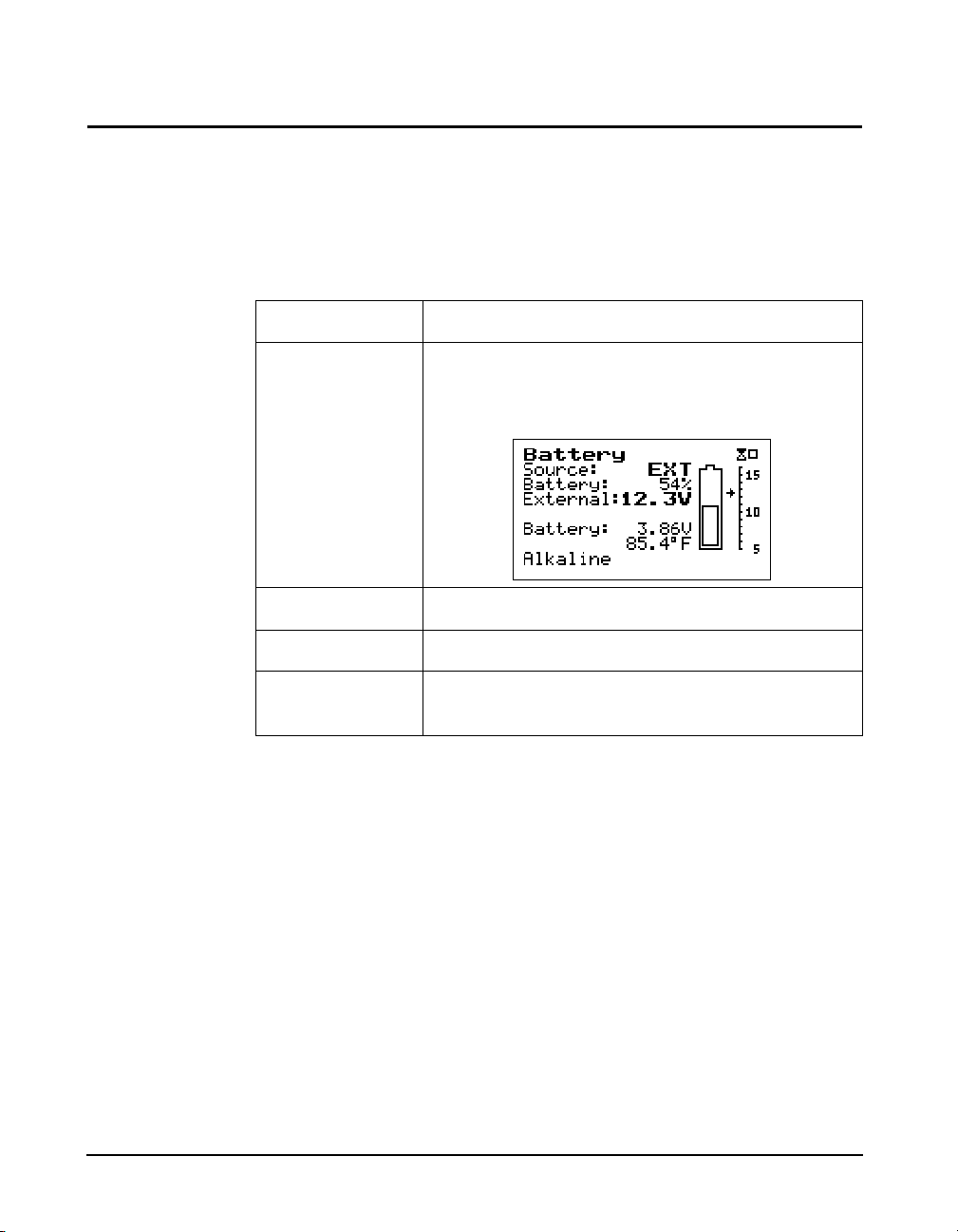
Power Settings
Use the u and d keys to move
from one setting to the next. Then use
the
r key to change the selected
setting. The
return to previous menus.
l key is used to
Menu Items Description
Status
Settings Described later in greater detail.
Charge Activates the smart battery charger.
Type Select Alkaline or NiMH for individual cells. See
The Power menu provides the following menu items:
Display’s the Power Monitor display that shows the
current battery type and charger status.
Connecting Internal or External Power” on page 1-18
Once the smart charger has been activated the 824 will not
allow you to shut it off when the power key is held down.
The 824 will beep and give the warning “Charging Battery,
Please Wait”. Simply press the power key again to force the
824 to shut off.
The charge mode will be activated
automatically when external power
is applied and the battery is at 75%
capacity or less.
WARNING!
Whenever external power is applied, the 824 will trickle
charge to keep the battery pack at full charge
The 824 must have external power applied and
be left “ON” in order for the battery pack to
charge!
3-6 824 Reference Manual 9/29/09
Page 65

The power Settings menu item provides the following eight
settings:
Menu Items Available Setting
Description
Options
Power Off Mode Blank LCD
Auto Off
Manual Off
Blank LCD - The instrument LCD display and serial
communication port, will turn off after the keyboard
and serial port have been inactive for the period of
time set by the
Auto Off - If the instrument is stopped with no reports
printing, and the instrument remains inactive (i.e
with no serial interface commands or key presses),
for the period of time, set by the
ting, the instrument will turn off.
Manual Off - No automatic power reduction features
are enabled.
Auto Off Time 0 - 99 minutes When
down in the specified number of minutes of inactivity.
Standby Time 0 - 99 minutes
Time (in minutes) when Standby Time power save is
activated. When activated, the System 824 screen
blanks and the serial port turns off. If any key is
pressed or if incoming serial activity is detected, the
instrument will exit Standby Time and become
active again.
Standby Time setting.
Auto-Off Time set-
Auto Off is activated, the System 824 powers
Backlight Time 0 - 99 seconds Time (in seconds) when the backlight is turned off.
The backlight is reactivated when any key is
pressed.
Backlight On/Off Turns backlight on/off.
LCD Contrast 0 - 99%
(The default contrast
setting is 66%)
Adjusts the contrast or viewing angle of the LCD
display. This is done by pressing either the up or
down arrow key. The
u key increases the contrast
percentage, darkens the display and makes it visible
from a higher angle (when viewing from the bottom
of the instrument). The
d key decreases the con-
trast percentage, lightens the display and makes it
more visible from a lower angle.
9/29/09 Front Panel Keys; Functions and Menus 3-7
Page 66

External Power AC Pwr
Battery
AC Pwr - Indicates that the external power source is
not a battery. If the external voltage is less than the
internal battery voltage, then the internal batteries
will supply power for the instrument.
Battery - Indicates that the external power source is a
battery (which should not be allowed to deep-discharge).
Min Battery 0 to 15.9 (10.8 volts
is the default setting)
Sets the external cutoff voltage when a battery is
used for external power. 10.8 volts DC is the recommended setting for a 12 volt battery.
Extra Notes on Power Conservation
NOTE: To exit the Power display, press
the left larrow key or use the view
key to the select desired view.
WARNING! Battery life is reduced by approximately 25% with the back-
WARNING! Loss of power may cause loss of memory
WARNING! Turn off power to change the microphone or preamplifier.
If you are using an external power supply, the v key will
display the constant voltage coming from the power supply.
If the external battery supply ever drops below 10.8 Volts,
set by the Min Battery setting, the 824 will automatically
turn off. Discharging some types of batteries (such as lead
acid) deeply will greatly shorten their service life.
For detailed information on the use of external power, see
"Power/Current Draw of 824 Using External Power" on
page C-49
light on.
Sensitive electronics can be damaged by voltage spikes.
s Run/Stop Key
Use the s RUN/STOP key to toggle the data gathering
mode of the instrument from stop to run, or from run to stop.
The mode of the instrument is indicated on the display in the
upper right hand corner by a running man symbol if the
3-8 824 Reference Manual 9/29/09
Page 67

instrument is running, or a box symbol if the instrument is
stopped.
NOTE: The Indicator Box in the upper
right hand corner of the display will be
solid if data is present, or open if no data
has been taken.
R Reset Key
The SSA, ISM, and LOG instruments
within the System 824, contain two
independent data buffers that can
separately accumulate data. In
essence, the instrument becomes two
sound level meters in one. The data
in the primary buffer is referred to as
the “overall” measurement, while
data in the secondary buffer is
referred to as the “current”
measurement.
Repeatedly pressing the s RUN/STOP key after beginning
a measurement will stop, then restart the measurement without resetting the data buffer. As a result, the time will continue to increase for the overall measurement.
The R RESET key allows you to clear the data of the current measurement.
If you are using the simple sound level meter (SLM) instrument and wish to reset the data, simply press the
key. This will reset all the data including the accumulated
measurement values such as L
For the other instrument types, the System 824 gives additional flexibility when resetting the data. If you press the
RESET key while the instrument is running, the instrument will reset its data buffer for the current measurement
and set the elapsed time for the current measurement to zero
without affecting the data in the overall measurement.
If you press the
stopped, a menu will appear that will give you the choice of
resetting the current data or the overall data together with the
appropriate elapsed time counters.
R RESET key while the instrument is
.
eq
R RESET
R
When editing system or instrument settings containing a
string of numbers or characters, the
be used to clear the characters from the current position of
the cursor to the end of the string.
9/29/09 Front Panel Keys; Functions and Menus 3-9
R RESET key can also
Page 68
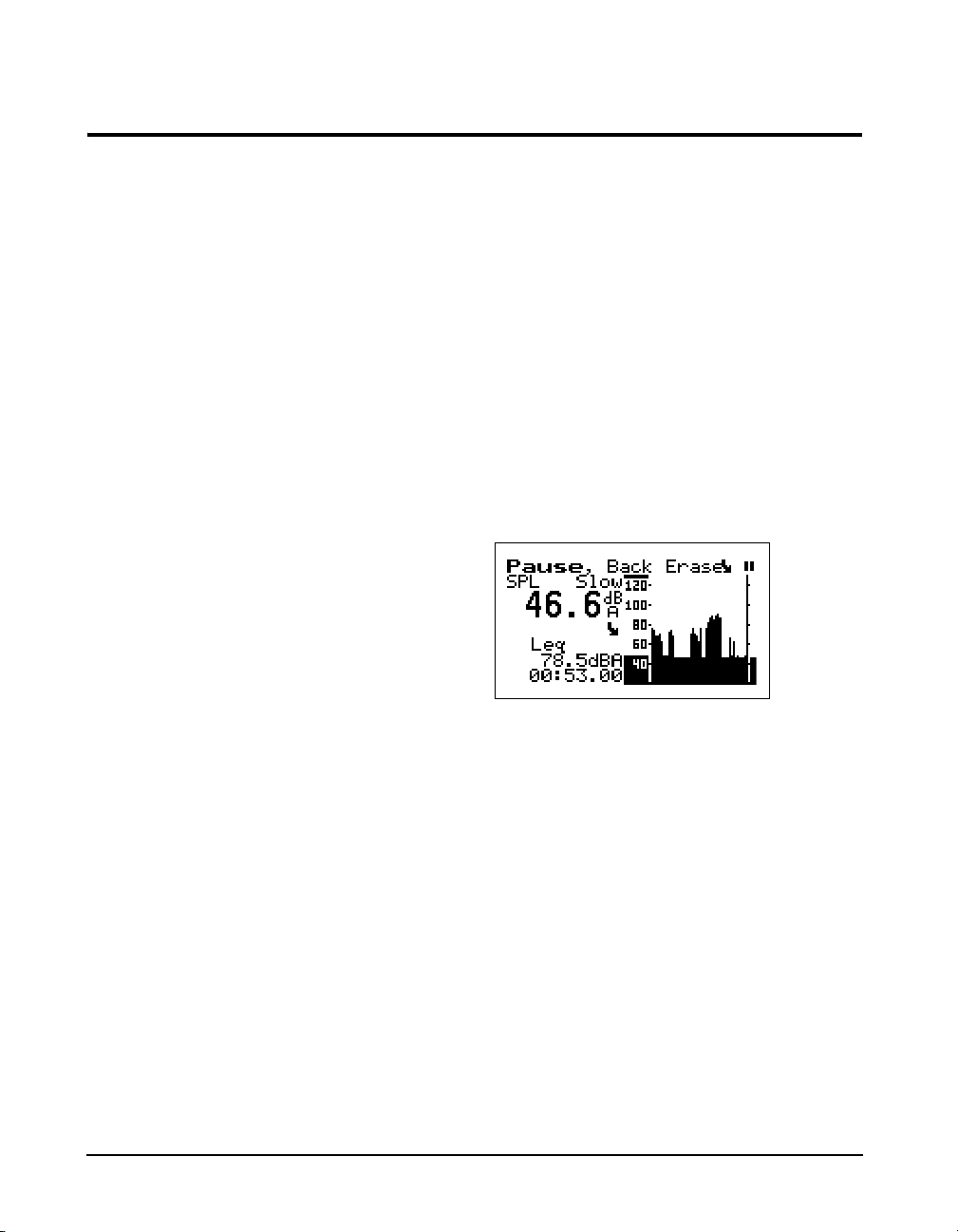
p Pause Key
The p PA U SE key has 3 basic functions in the ISM and
SSA instruments: To Pause a measurement to avoid
unwanted noise from entering into the measurement data. To
erase unwanted data from the measurement and to preview
the data coming into the instrument without registering the
data.
Pause The first function of the Pause key will cause the instrument
to not accept any incoming data. Unlike pressing the stop
key, pressing the pause key will not start a new measurement, but rather will simply pause the existing measurement
for a moment. After the desired pause period, press the
pause key
lowing screen will appear.
p again to resume the measurement. The fol-
Pause, Back Erase The second function of the pause key is to remove unwanted
data from the measurement. The cursor is used for this funciton. The
the graph.
NOTE: Moving the cursor bar left is like
moving back in time.
3-10 824 Reference Manual 9/29/09
Once it is at the desired point, press the c key to delete the
data to the right of the vertical bar. After the instrument has
deleted the unwanted data, the measurement will resume
automatically.
landrarrow keys move the cursor across
Page 69

Preview Pressing the p PAUSE key when an instrument is
“stopped” brings up a Preview display which allows you to view the SPL without affecting measured data. Pressing the
p PAUSE key again will exit this screen or simply press
the
s RUN/STOP key to exit this screen and start taking a
measurement.
lrud Arrow Keys
The u and d (Up and Down) arrow keys navigate
from one item to another in a menu, or from one record to
another when displaying history data. Pressing and holding
an arrow key will repeat the actuation of the key. These keys
are also used to modify settings. Use the
the next higher number or character value, and use the
key to step to the next lower number or character value.
u key to step to
d
Pressing and holding an arrow key
will repeat the actuation of the key.
The repeat rate increases as the key
is pressed for a longer period of
time. Key pressure also has an effect
on the repeat rate as does the
amount of data available to view.
9/29/09 Front Panel Keys; Functions and Menus 3-11
The
landr(Left and Right) arrow keys move between
data displays, to move between characters of a setting being
modified and to move through menus. Use the
key to move from the current menu into a sub-menu or to
modify a setting. Use the
ting, to move from a sub-menu back to its parent menu, or to
move back to a previous menu or display. The
(Left and Right) arrow keys will also move the vertical cursor bar within certain measurement displays.
larrow key to move out of a set-
r arrow
l and r
Page 70
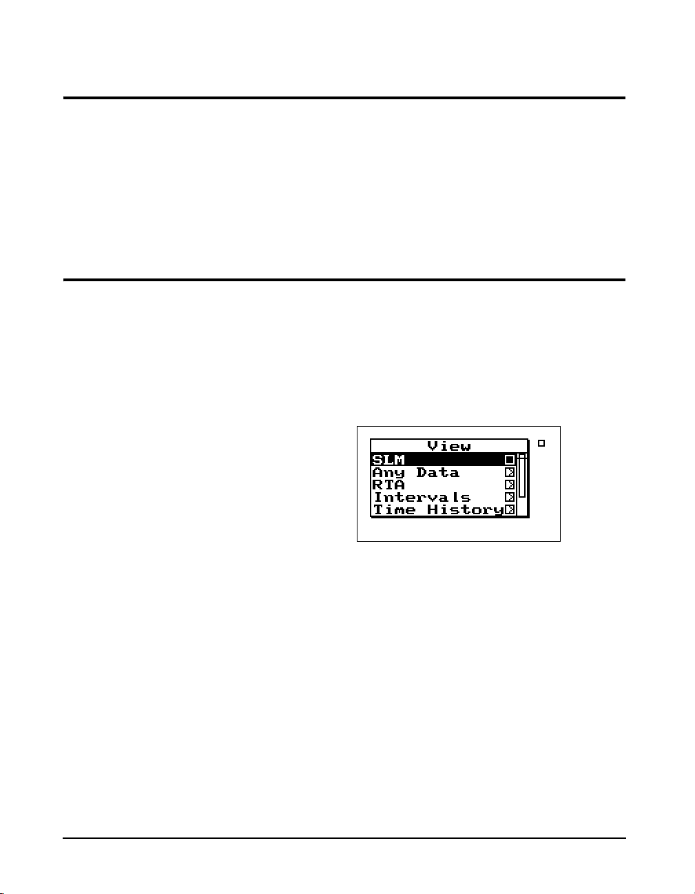
c Check Key
The c key allows you to choose an item from a menu or to
confirm the entry of a setting.
V View Key
Pressing
which you can make changes to settings appropriate to that
display.
The display of data on screen of the System 824 is controlled
by the
or LOG) has its own set of available data displays which are
selected using this key. When you press the
containing the available data displays will appear. The following example is a View menu for the SSA instrument:
The
desired display. While viewing data, often more than one
display screen is available. You can use the
arrow keys to move from one screen to another.
c in many displays will bring up a menu from
V VIEW key. Each instrument type (e.g. SSA, ISM,
V key, a menu
uordkeys and c key allow you to select the
l and r
The data displays available under the
instrument type used to measure the data. These will be
described in more detail in later chapters dedicated specifically to each instrument type.
3-12 824 Reference Manual 9/29/09
V key depend on the
Page 71

D Data Key
The D DATA key controls the storing and recalling of
measurements, or data files from memory. Each file may
contain cumulative data, time history, interval history, calibration data and histogram tables that can be stored as distinct measurements from other measurements with their data
and histories. A list of all stored measurement data is shown
and individually recalled by selecting it using the arrow keys
and check key.
If no data files have been saved, the
Recall option will not be available
for recall.
If the instrument is running when
you try to store a Data File, you will
be prompted to stop the
measurement before storing the file.
To view a data file, use the
uor
d keys to select the desired data
file. Each data file is marked with a
number and the instrument used
(e.g.: SLM&RTA SSA).
To access the Data Files menu press the
screen similar to the following appears:
From this menu you can store data or view and recall stored
data.
To store measurement information into a Data File, highlight Store File using the
key to select. The instrument will beep once to signify that
the measurement has been stored.
Press the
a summary of the stored data files. The following screen
appears:
D Data key again and select Recall Files to view
u or d keys. Press the c
D DATA key. A
9/29/09 Front Panel Keys; Functions and Menus 3-13
Page 72
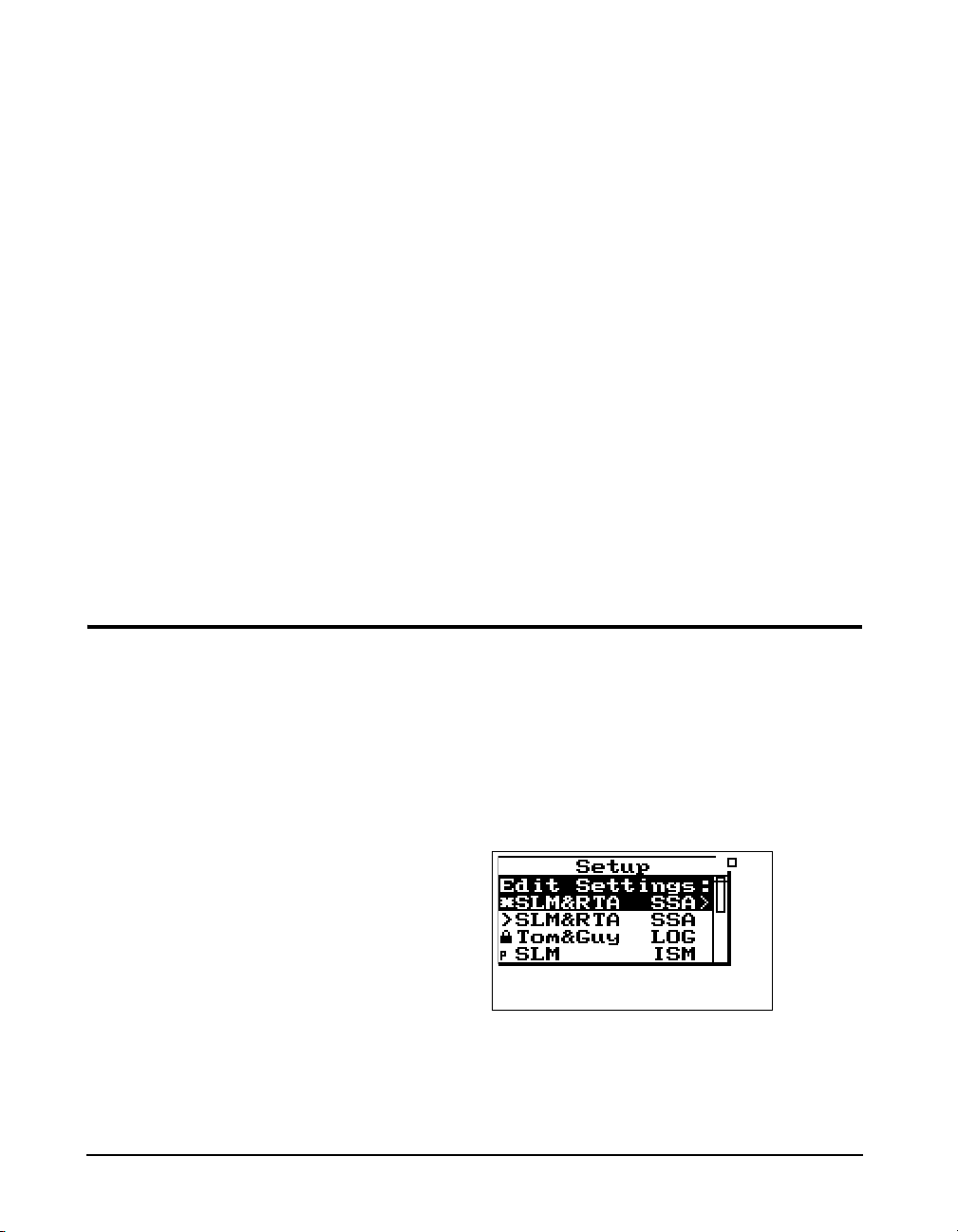
To move from one record to another,
use the
uordkeys.
To exit the Data Files view, press the
lto return to the previous display
or select a new view using the
VIEW key.
V
The Data Files screen shows the currently selected record
number (1/4), start & stop dates and times, and the total
bytes used by the record.
Pressing the
Files menu, allows you to recall that measurement. An
active data display will be shown.
c key and selecting Recall File from the Data
Pressing the
Files display, brings up a menu that
allows you to recall data, jump to
beginning or end of all records, find
a specific data file, or purge all data
files.
c key from the Data
S Setup Key
To the left of each ID is a symbol
giving information about that ID:
The ‘>’ symbol indicates that the ID
is currently active or that the ID is
currently in memory. The lock
symbol indicates that the ID is
locked which protects the ID from
being easily deleted. Press TOOLS
to write protect or un-protect an ID.
The ‘p’ symbol indicates that the ID
is permanent and pre-defined.
The’
’ symbol indicates that the ID
*
has changed and has not yet been
saved.
When recalling a data file, the System 824 will switch to the
instrument definitions (ID) that the data file was stored as
(i.e. SLM&RTA to Logging, if the user was currently using
the SLM&RTA instrument and recalled a Logging data file).
If the run key
active, the data is reset and the new data is taken using all of
the settings that were stored with that data file.
The data file also contains calibration information that may
be different than the current calibration. When Run is
pressed, the recalled calibration is replaced by the latest /current calibration.
Use the
can select, create, and manipulate groups of instrument settings known as “instrument definitions” (ID). The Setup
menu presents a list of pre-defined IDs (marked with a “p”)
and user-defined IDs (if previously configured) that are
available for use. To access the Setup menu, press the
key. A screen similar to this appears:
S SETUP key to access the Setup menu where you
s is pressed while a recalled data file is
S
An ID defines the data that is to be measured for a particular
project or type of application. The defined project IDs are
listed in the Setup menu. You can create, edit, copy, and
delete these project settings within this menu. You can also
3-14 824 Reference Manual 9/29/09
Page 73

define a project ID on a computer using the 824 Utility software and then install it into the instrument where it may be
selected for use. For example, one project may require the
“simple SLM” where no data logging is performed and the
weighting and detector controls are available in the data display (rather than in a menu). Another example may be an
hourly statistical measurement set to run for 8 hours using a
LOG ID.
If data from a previous ID was not
saved, you will be prompted to do so
at this time. If settings to the current
ID have been made, you will be
prompted to save the ID at this time.
The ISM and AUD instruments do
not issue these prompts.
To select an instrument definition (ID), use the
keys to highlight the desired ID. Press the c key to select
and activate the it. The Setup menu then closes and the main
display appears.
The modification of a selected ID to meet the requirements
of a particular measurement application is an entire topic in
itself which will be addressed in general in the next chapter
and in detail in later chapters individually describing the
setup and operation of each of the instrument types available
for the System 824. However, once these modifications have
been made, the new ID is named and stored as described in
the following section.
Use the Setup Tools menu to create new IDs. To do this,
press the
menu option. Press the
lowing screen:
S SETUP Key and highlight the Edit Settings
T TOOLS key to display the fol-
u or d
With the Setup Tools menu you can create and/or modify
instrument definition (ID) settings. The Setup Tools menu
provides the following three options, which are later
described in greater detail.
9/29/09 Front Panel Keys; Functions and Menus 3-15
Page 74

:
Menu Items Description
Save ID Saves/Creates an ID
Title Description of ID
ID Name Name of ID
Save ID The Save ID menu item saves or creates an ID. Use the
or d keys to highlight Save ID, then press c. You will
then be prompted to verify the name for the ID. (See ID
Name below)
Title You can attach a description to your ID with the Title menu
item. This description can be used on printed reports and
other items. The Title field is capable of holding up to 30
characters.
ID Name You use the ID Name menu item to give an ID a unique
name that represents the ID in the Setup menu. The ID
Name field is capable of holding up to 8 characters.
Name format: “cccccccc.ccc” The first 8 characters form the
name and the last three are the extension that indicate the
instrument type (e.g. “SSA”). The name does not have to be
a full 8 characters long. Leading spaces and symbols will be
removed from a name. Case is preserved but ignored when
finding names. Embedded spaces will be converted to underscore. The name should start with a letter or number. The
characters generally used in a name are A to Z, 0 to 9, and _
- (underscore, and dash) but may also be “ ‘ ( ) [ ] !@ # % $
^ &.
u
The allowed characters in names for IDs are compatible with
PC filenames. The following characters are NOT allowed:
* + , . / : ; < = > ? [ \ ] |
3-16 824 Reference Manual 9/29/09
Page 75

Write Protect, Delete, Write Enable IDs
NOTE: Within a given active instrument
definition (ID), write protect or delete
operations cannot be performed on files
that were stored using that same ID. In
order to protect or delete these files, the
active ID must be changed. For example,
stored FFT files can be protected or
deleted by switching from the FFT ID to
an ISM, LOG, or RTA ID.
The ID that is active, with a “>” by
it, cannot be deleted.
Permanent IDs (marked with a ‘p’ in
the Setup menu) cannot be write
protected, modified, or deleted.
Write protected IDs (marked with a
locked symbol on the Setup menu)
cannot be deleted. The icon will not
be displayed if the currently active
ID is being used. Also, the currently
active ID cannot be deleted.
After an ID has been created, it can be protected (or locked),
or deleted if necessary. To do this, use the
from the Setup menu to highlight the desired ID.
Press the
To write protect (or lock) an ID, use the
highlight Write Protect, and then press the
symbol appears next to locked IDs in the Setup menu
(except for the current running ID) and symbolizes that this
ID is “Write Protected”. Once the ID is write protected, it
cannot be changed or deleted until it is “Write Enabled”.
To delete an ID that has not been write protected, use the
T TOOLS key, and the following screen appears:
u or d keys
u or dkeys to
c key. A locked
u or d keys to highlight Delete ID, then press the c
key. The ID is removed from memory and the ID name is
removed from the Setup menu.
To write enable (or unlock) an ID, use the
from the Setup menu to highlight the desired write protected
ID (marked with a locked symbol). Press the
key. Press the
option. The locked symbol disappears next to the ID shown
in the Setup menu, symbolizing that this ID is write enabled.
c key on the highlighted Write Enable menu
u or d keys
T TOOLS
9/29/09 Front Panel Keys; Functions and Menus 3-17
Page 76

TTools Key
NOTE: In certain situations you also use
T TOOLS key to delete, write
the
enable, or write protect instrument definitions (ID) from the
previously described).
NOTE: From any of the following displays, the u and d arrow keys will
step to the next or previous display in the
list.
Menu Item
About Name (company name)
Setup menu (as
Available Settings Options
(
rkey from Tools menu)
Name (address line 1)
Name (address line 2)
Title (30 characters)
Date Format (Normal or ISO-
8601)
Takt (enables Takt functionality) Yes or No
The T TOOLS key allows you to access controls and operations such as calibration, battery usage, memory usage, setting date and time, timer, or computer port settings. You
press the
ify settings press the
Tools menu. Pressing the
Tools menu allows you to view system settings and other
displays.
The Too l s menu provides the following seven options,
which are afterwards described in greater detail:
T TOOLS key to access the Too ls menu. To mod-
r key on a menu item from the
c key on a menu item from the
Setting Screens
( c key from Tools menu)
a - System revision information
b - User information
c - Installed instrument options
Calibration Check
Change
Cal Level
Calibrator S/N
Noise Floor (not all versions)
3-18 824 Reference Manual 9/29/09
Calibration - dates, times, and measurement when checked or changed
Page 77

Clock/Timer Current Time
Current Date
Day of Week
Timer Mode
Run Date
Stop Date
Run Time 1
Stop Time 1
Run Time 2
Stop Time 2
Memory Delete Last
Purge All Data Files
Allocated IDs
Create EEPROM Backup
a - Current time, date, and time of next
action
b - Timer mode status and settings
a - Memory status & current
instrument record information
b - Overall record status
Power Monitor Display Power Status
Power Settings >
-Power Off Mode
-Auto-Off Time
-Standby Time
-Backlight Time
-Backlight
-LCD Contrast
-External Power
-Min Battery
Activate Battery Charger
Type
Communication Baud Rate (300 - 115 K)
Serial Address
Flow Control
Modem>
-Modem Mode
-Dial Out Mode
-Phone #
-Monitor Number
-Modem Init
Battery and external power status, battery
type, and internal temperature
Lists command characters received and
data characters sent by the instrument. Also
shows the current standby timer status. The
serial port and display are turned off when
the timer reaches 0.
9/29/09 Front Panel Keys; Functions and Menus 3-19
Page 78

About
Instrument model number
Instrument serial number
Internal firmware revision number and date
Internal SLM firmware revision number and date
To access information about the System 824 use the u or
d key to select About from the To ol s menu, then press the
c key. The following screen appears:
The About-a display shows the instrument’s model number
and serial number as well as the firmware revision number
and date.
The revision number indicated by
“REV:” is changed when any
firmware code change is made. The
revision number indicated by
“SLM:” is changed only when a
firmware code modification is made
that affects the accuracy of any SLM
measurement data, and is used as an
indicator to those who use third
party verification (NIST or PTB,
etc.) of instrument performance that
testing should be performed.
About Settings edit mode can also be
edited by pressing the
the About display screens
(previously described).
3-20 824 Reference Manual 9/29/09
c key from
Pressing the
lowing appears:
The About-b display shows the instrument’s custom name
and title fields printed on System 824 reports. The fields are
generally set to the owner’s name and address. The name is
displayed at “power on” and printed on reports to customize
them to your business.
To modify the About settings, use the
select About from the Too ls menu, then press the
The About setting offers three Name fields and one Title
field for use on System 824 reports.
Company Name, Address Line 1, Address Line 2- There
are three lines available for user specific data. Each field
rkey moves to the About-b screen. The fol-
u or d key to
r key.
Page 79

provides 30 alpha/numeric characters, and is used to
Company name and address
(Customized by user)
describe the instrument or the organization to whom it
belongs.
Title - Like the Company Name field, the Title field is capa-
ble of holding 30 alpha/numeric characters. It allows you to
title the ID (Instrument Definition) you have created, and to
describe your measurement.
Date Format - Displays the date in Normal or ISO-8601
format. Normal has the form of ddmmmyyyy and ISO-8601
has the form yyyymmmdd where dd is the two digit date of
the month 1 to 31, mmm is the month (i.e. JAN) and yyyy is
the year (i.e. 2000).
See the section "Any Impulse
Format" on page 5-8 for optional
Takt views.
9/29/09 Front Panel Keys; Functions and Menus 3-21
Tak t - Enables Takt functionality to give you taktmaxmal
values.
Press
ltwice to exit the menu.
Pressing the
rkey again moves to the About-c screen. The
following screen appears:
Page 80

Calibration
Date and time of the last calibration change
Offset currently in use to calibrate the levels
Date and time of the last calibration
The level detected during the last check
The About-c display shows the system’s currently available
instruments. Additional instruments can be added to the System 824 through firmware upgrades as they become available.
Checked instruments are installed and available for use. The
number of demos used is indicated. Only 20 demos are
allowed. When “demos used” equals 20, options not purchased are no longer available for use. If you have found
them useful, they can be installed permanently without
restrictions. Call Larson Davis for details.
To calibrate the System 824, or to view previous calibration
information, use the
from the Too ls menu, then press the
screen appears:
u or d key to select Calibration
c key. The following
3-22 824 Reference Manual 9/29/09
The Calibration display shows the date and time of the last
calibration change and the offset being used to calibrate the
levels. It also shows the date and time of the last calibration
check and the level detected during that check.
To utilize the calibration tool or modify the Calibration settings, use the
Tools menu, then press the
provides the following settings:
Check - Activates the calibration check (level verification)
process.
u or d key to select Calibration from the
rkey. The Calibration menu
Page 81
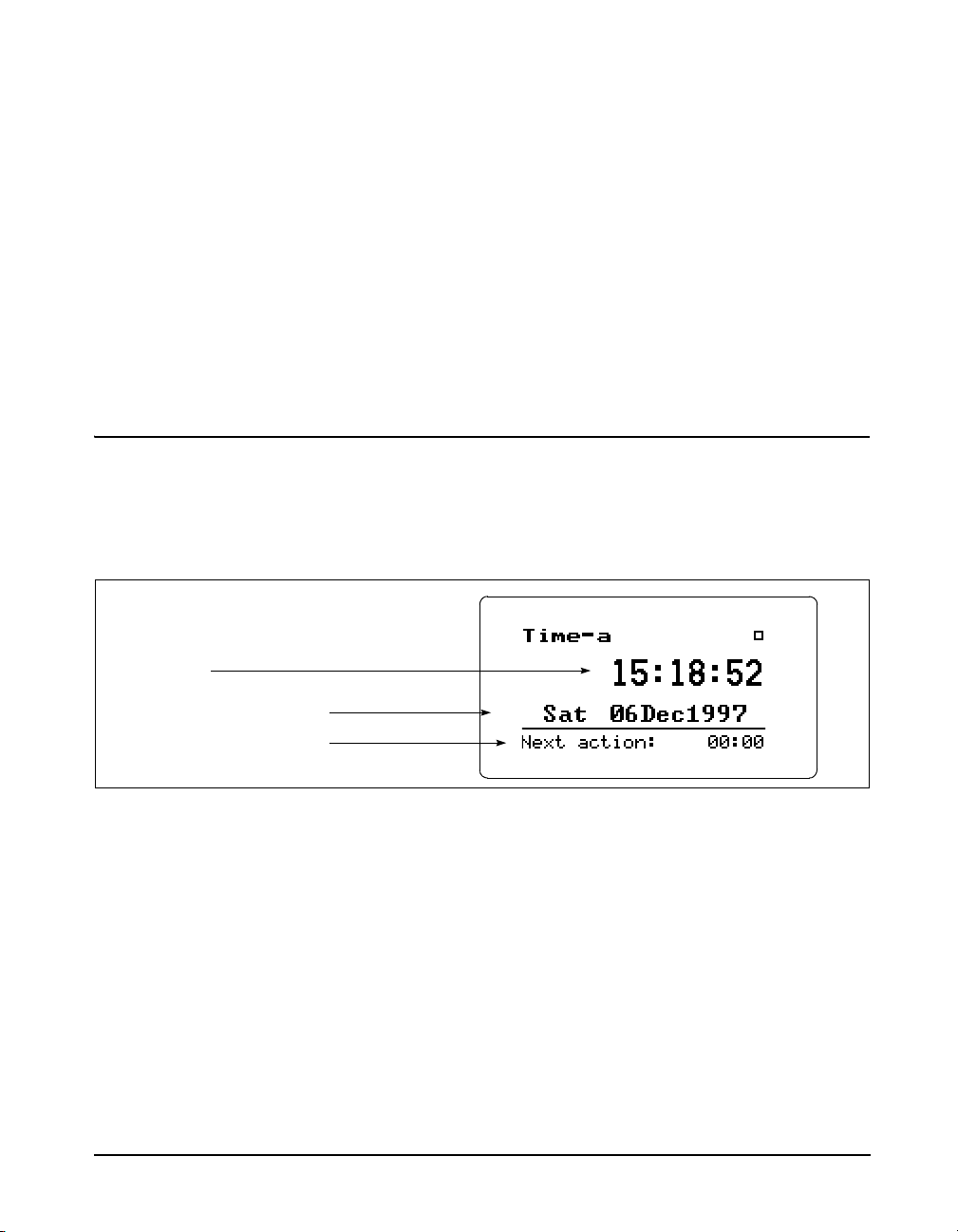
Clock/Timer
Current time
Current day of the week and date
The time of the next timer function
Change - Activates the calibration change (adjust) process.
Cal Level - Enables the user to enter the sound pressure
level generated by the calibrator.
Calibrator S/N - Enables the user to record the serial number of the calibrator (for reference).
Noise Floor - Enables the user to enter a noise floor value.
Optimum values will depend on the type of measurement
being performed. For a more detailed description, See
“Entering the Noise Floor Values” on page 9-4.
To display the time and date, or to view the timer settings,
use the
Tools menu, then press the
u or d key to select Clock/Timer from the
c key. The following appears:
Clock/Timer Settings can be
changed by pressing the
the Clock/Timer display screen.
9/29/09 Front Panel Keys; Functions and Menus 3-23
c key from
The Time-a or clock display shows the current time, day of
the week, date and the time of the next timer action.
Pressing the
following appears:
The Time-b or timer display shows the current timer programming including the mode and the appropriate run and
stop times and dates.
To modify the Clock / Timer settings, use the
key to select Clock / Timer from the Too ls menu, then press
rkey again moves to the Time-b screen. The
u or d
Page 82

The currently-selected timer mode
The run and stop dates
The first run and stop times
The time of the next timer function
The clock in the 824 uses a 24 hour
format with hours 0 through 11
being a.m. and hours 12 through 23
being p.m. For example, 5 p.m. will
be displayed as 17:00:00.
therkey. A screen similar to the following will appear:
With the Clock / Timer menu you set the instrument's clock/
calendar and timer. The first three menu items allow you to
set the current time, date, and day respectively, while the
remaining items (Run/Stop Date, Run/Stop Time 1, Run/
Stop Time 2) allow you to control the timer function.
IF the date has not been set (month
shows as???) then the message
“Time not set!” will be shown when
the Run key is pressed.
3-24 824 Reference Manual 9/29/09
Current Time / Date - To set the current time and/or date,
highlight the desired item (i.e. Time or Date) and then press
the
rkey. Modify the setting using thelorrkey to
select the digit desired to modify, then use the
uor d
key to modify.
Page 83
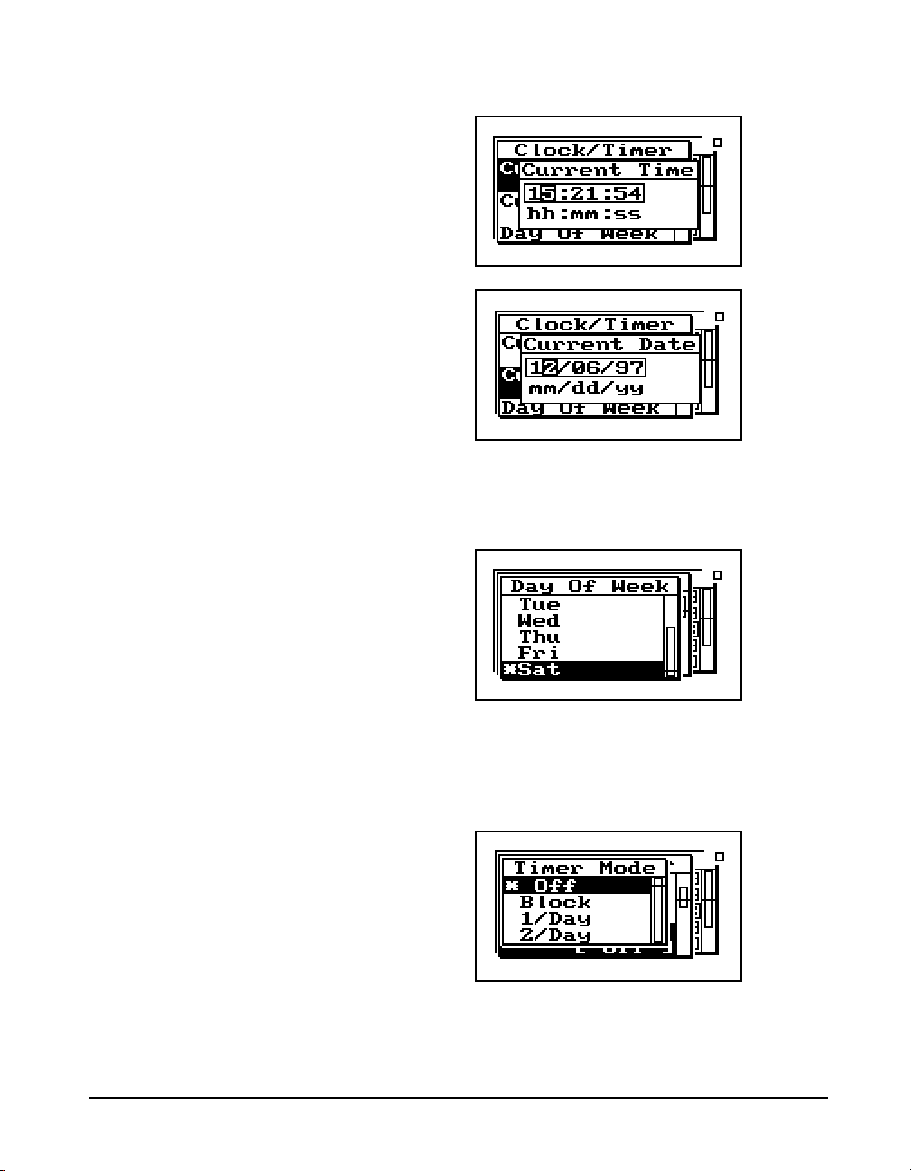
Day Of Week - Allows you to change the current day of the
week. Use the
then press the
Timer Mode - The timer is used when you want to have the
824 automatically turn on, gather data, and stop at pre-determined date(s) and time(s). The System 824 has four timer
modes automating the start and end of measurements:
u or d key to highlight the desired day,
c key to select.
Off - The timer is disabled.
9/29/09 Front Panel Keys; Functions and Menus 3-25
Page 84
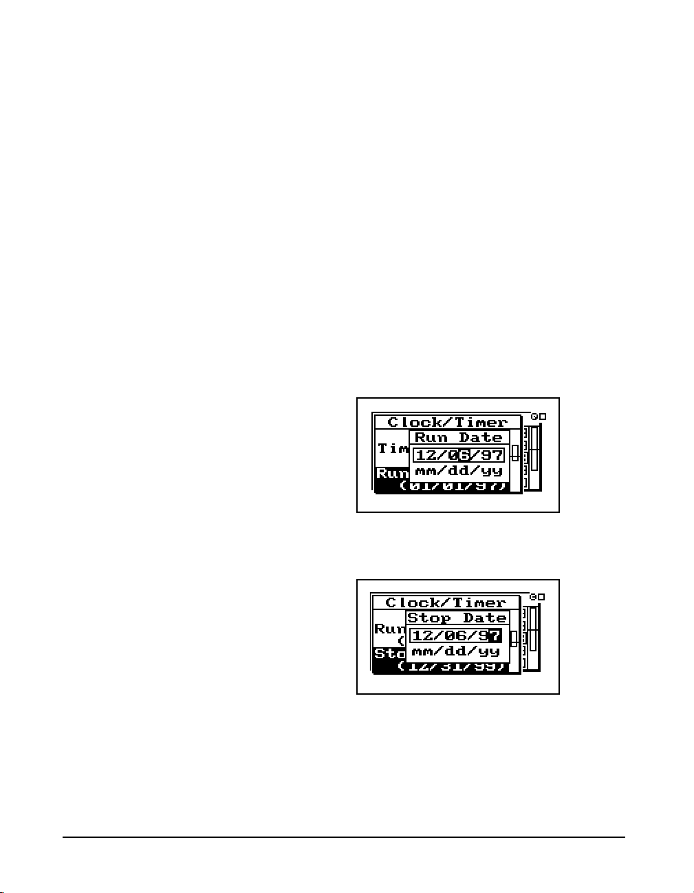
Block - The timer will automatically turn the
instrument on and initiate a single measurement
beginning at a certain time on one day and ending
at a certain time on the same or another day.
NOTE: If the run time is later than the
stop time, then a measurement will start
on the stop date and end at the stop time
on the date AFTER the stop date.
1/Day - The timer will automatically turn the
instrument on and initiate one run/stop cycle per
day from the run date until the stop date.
2/Day - The timer will automatically turn the
instrument on and initiate two run/stop cycles per
day.
The three “enabled” modes (i.e. 1/Day, 2/Day, and Block)
use the dates set by the Run Date and Stop Date menu items
to determine the range of “valid” days on which to make
measurements.
Run Date - Specifies the starting date to take measurements.
Stop Date - Specifies the date to end the measurement and
disable the timer mode.
Run Time 1 / Stop Time 1 - These settings allow you to
specify the beginning and ending times of a measurement.
3-26 824 Reference Manual 9/29/09
Page 85
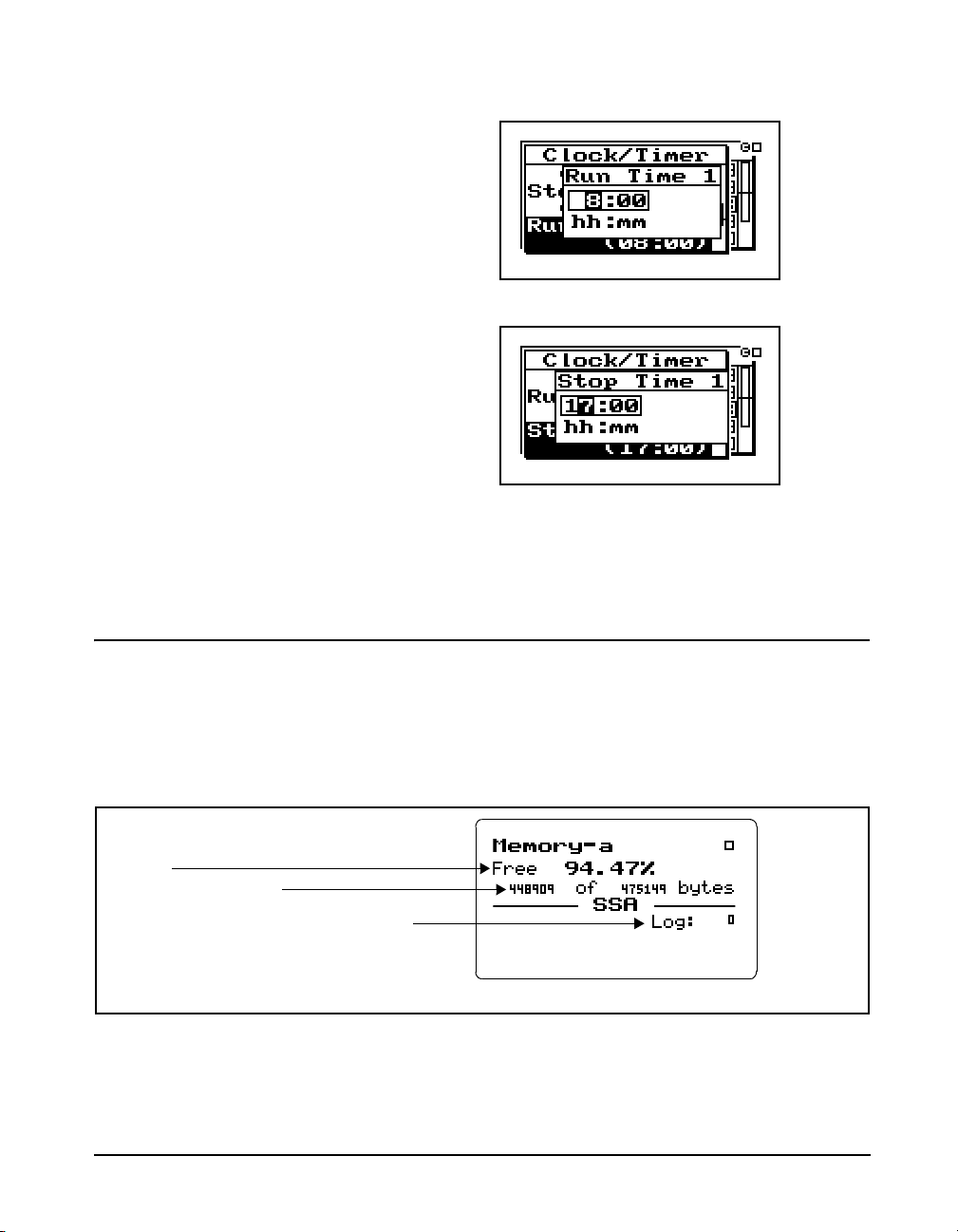
NOTE: If you have selected the Block,
Available memory (in bytes)
Available memory (as a percentage of total data
memory)
Number of various types of history records for a
given ID (SSA in this example)
1/Day
or 2/Day mode, the timer will
automatically turn the instrument on one
minute prior to the run time.
Memory
Run Time 2 / Stop Time 2 - These settings are used to specify a second measurement’s beginning and ending time in
the 2/day timer mode.
9/29/09 Front Panel Keys; Functions and Menus 3-27
To access the Memory display, use the u or d key to
select Memory from the To ol s menu, then press the
c key.
The following appears:
Page 86

For detailed information on the
Available memory (in bytes)
Available memory (as a percentage of
total data memory)
Number of setup registers allocated for storing
instrument definitions (IDs)
Total memory, including both data and setup register
memory
Total data files in memory
usage of memory (e.g. bytes for each
type of record stored), see "Memory
Usage" on page E-1
The Memory-a display shows the amount of memory available for storing data. This information is given both in bytes
and as a percentage of the total memory that can be used for
storing data. (This “total memory” does not include the
memory allocated for ID registers.)
Only those records enabled for the
active instrument type are displayed.
Memory Settings can also be
accessed by pressing the
c key from
the Memory display screen.
In addition, the Memory-a display shows the number of previously-stored records (of various types) for the active ID.
Pressing the
rkey again moves to the Memory-b screen.
The following appears:
The top portion of the Memory-b display shows the same
“available memory” information as in the Memory-a display. In addition, the Memory-b display shows the number
of data files in memory; number of setup registers allocated;
and the total amount of memory, including that memory
allocated for setup registers.
To modify the Memory settings use the
select Memory from the Tools menu, then press the
u or d key to
r key.
See next page for detailed
information on the “Delete Last”
feature.
“Purge All Data Files” is also
available from the reset menu under
the RESET
3-28 824 Reference Manual 9/29/09
R key.
Delete Last - The Delete Last feature will allow the user to
delete the very last record stored in memory from any instrument type. To delete the last stored record, highlight Delete
Last and press the Check
Purge All Data Files - Pressing the
c key.
ror c key when the
Purge All Data Files menu item is highlighted, allows you
to purge all data files in memory. This clears the memory.
Page 87

The default value of this setting is 10
allocated setup registers (which uses
5120 bytes of memory). The System
824 has ten permanent ID registers.
These pre-defined ID registers
cannot be changed or deleted and do
not reduce the amount of data
memory available. They are to be
used primarily as templates for new,
user-defined IDs.
Allocated ID’s - Determines the number of setup registers
that are allocated in memory for storing IDs. In essence, this
setting determines how much memory is allocated for storing instrument definitions. Setting this to a higher value
allows more IDs to be created, but reduces the amount of
memory available for data storage by 512 bytes per allocated
ID.
Create EEPROM Backup - Stores the most recently used
SSA, ISM, and LOG IDs so that they may be recreated in the
event of a memory loss.
Important: In order to not lose your
customized settings in the event of
memory loss or firmware upgrade,
follow these steps.
1. Alter the permanent IDs as desired and save your
customized setting using a name of your choice.
2. Enter the unit Name and other system settings in the
TOOLS>About menu
3. Bring your favorite ISM, LOG and SSA ID to the top of
the SETUP ID menu by selecting them one at a time. Alter a
permanent ID and save your customized setting using a
name of your choice.
4. Store these settings permanently using the TOOL>Mem-
ory>Create EEPROM Backup menu item.
Your settings will not become permanent.
Repeated whenever you update any of the system settings or
IDs that you want to be permanent.
Deleting Stored Data
Delete Last Function The Delete Last feature will allow the user to delete the very
last record stored in memory from any instrument type. It
also allows you to recall a file, delete individual records
within that file, run the instrument again and append new
data to memory. Essentially the record is unstored from
memory.
824 Memory Structure The memory structure of the 824 is a forward and reverse
linked list. This means that for each type of data there is a
pointer to the first record and a pointer to the last record and
9/29/09 Front Panel Keys; Functions and Menus 3-29
Page 88

that each record points to the next record and the previous
record. This structure makes the memory very efficient
(compared to fixed sector, file allocation table based memory structures) and sequential forward and reverse data
retrieval is very fast.
This memory structure does not allow us to delete data in the
middle of used memory in a way that would allow it to be
reused. However, there is no problem deleting data from the
last to the first.
Deleting the Last Stored Record
If “View Back” is selected you will be
returned to the last view screen
displayed.
If nothing is selected after a 30
second time period, this screen will
disappear and return to the previous
display.
Step 1 To delete the last stored record, press the TOOLS
T key to access the TOOLS menu. The follow-
ing menu appears:
Step 2 Highlight “Memory” and press the right
key.
Step 3 Highlight “Delete Last” and press the Check
key.
rarrow
c
This display shows the last record that was stored along with
the date and time of the data, the instrument type it is
3-30 824 Reference Manual 9/29/09
Page 89
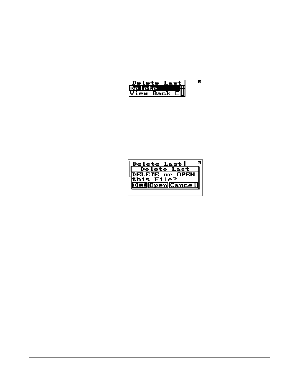
recorded for, the bytes used by that record and how much
memory is available.
Step 4 Press the Check
lowing menu will appear:
Step 5 Highlight “Delete” and press the Check
The record is deleted. If the last record was a data
file then the following choices will appear:
DEL - Choosing “DEL” will erase the file and all of its contents.
c key to delete this file. The fol-
c key.
Choosing “Open” also allows you to
delete individual records from the
file after it has been opened. See the
next page for instructions on
deleting individual records. In
essence this will UNDO the storing
of a data file.
Deleting Individual Records After selecting “Open” in Step 5 above, the file record is
9/29/09 Front Panel Keys; Functions and Menus 3-31
Open - Choosing “Open” recalls the file into memory, the
File record is deleted, and the data in memory marked as if it
had never been stored. This allows you to run the instrument
again and store the old data and the new data just acquired
into a new file.
Cancel - Choosing “Cancel” cancels you out of the Delete
File function and returns you to the previous display.
deleted and now you are allowed to look at each individual
record and decide whether to delete or store it with new data
appended to it. Follow these steps to delete individual
records:
Step 1 The last display that was viewed will appear after
selecting “Open”.
Page 90

Step 2 Press the TOOLS T key and the following
appears:
Step 3 Highlight “Memory” and press the right
key to access the “Delete Last” function.
Step 4 Highlight “Delete Last” and press the Check
key.
The records will appear one at a time. Below are examples
of some of the records.
rarrow
c
To delete them press the Check
appear:
3-32 824 Reference Manual 9/29/09
c key. The following will
Page 91
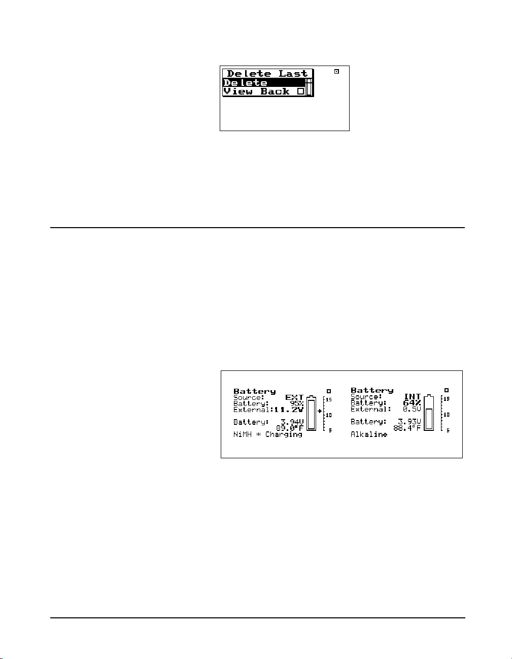
Power Monitor
With “Delete” highlighted, press the Check c key again to
delete the record. The next record will appear. Continue this
process until you have deleted all of records that you don’t
want.
This menu option allows adjustment of the auto-power off,
the contrast (or viewing angle), turns the backlight on or off
and adjusts settings that control the power-conservation features. Refer to the section “
3-3 for a full description of the Power Monitor settings. In
the following example of the Power Monitor display, the
battery indicates 3.49 V while charging. When the instrument is running, this will typically be 3.6V or less.
v POWER key” on page page
9/29/09 Front Panel Keys; Functions and Menus 3-33
Page 92

Communication
Shows the minutes of inactivity
remaining before the serial interface
powers down
Shows the last characters sent (none in
this example)
Shows the last characters received
(none in this example)
Indicates 824 is ready to
receive commands
Indicates controlling
device (computer,
modem, etc.) is
Indicates current address
status.
The Communication display shows the status of the serial
port (i.e. how many minutes until the standby mode is automatically enabled) and the last characters received and transmitted and is used when troubleshooting communication
problems and as an aid when writing programs to control the
instrument.
This menu can also be accessed by
pressing the
communications display.
c key on the
Use the right and left arrow keys to
toggle between the Communication
display and a list of Errors or Warning Messages. These messages are
useful when troubleshooting I/O
command problems.
To access the Communication display, use the
u or d
key to select Communication from the Tools menu, then
press the
c key. The following appears:
To access the Communication settings, use the u or d
key to select Communication from the Tools menu, then
press the
r key. A menu similar to the following appears:
The printer has its own baud rate for
printing reports and is not affected
by this setting.
3-34 824 Reference Manual 9/29/09
Baud Rate - Speed at which the System 824 communicates
with controlling devices (computer, modem, etc.) through
the serial port. The baud rate has a range from 300 to 115200
baud.
Page 93

Default is set to the value of the last
2 digits of the serial number and can
be set within the range of 1 to 100.
Serial Address - Address of instrument. This setting identifies the instrument within a network of instruments by
assigning it a network or serial address.
Flow Control - Flow control of the serial connection. Flow
control can be changed to None, Hardware, Xoff, or Both.
Flow control prevents the loss of data when either the instrument or controller’s input buffer becomes full. Hardware
flow control is recommended.
See the section "Modem Control
Mode (All Instruments)" on page A-
Modem Mode - Turns the modem mode on or off to allow
communication to a telephone modem.
74 for more detailed information on
modem communication.
9/29/09 Front Panel Keys; Functions and Menus 3-35
Page 94

Dial Out Mode - The 824 will dial out on an Exceedance or
an Alarm or both.
Phone Number - The 824 will dial the phone number
entered here on the events selected in the dial out mode.
Monitor Number - The monitor number is used to identify
which 824 is being queried and is sent with the 824’s initial
announcement.
3-36 824 Reference Manual 9/29/09
Page 95

Modem Init - The modem initialization string is entered
here.
Initialize - The modem initialization string is sent out the
RS232 port.
P Print Key
Refer to the section "Printing
Reports" on page 8-2 for more
information on printing.
9/29/09 Front Panel Keys; Functions and Menus 3-37
The P PRINT key displays the printing options menu.
These options enable printing of graphical and tabular data
reports directly from the instrument to a serial printer. You
can create high-resolution presentation-quality reports when
printing to a laser printer because of the instrument’s PDL-3
(Page Description Language) capabilities. Draft-quality tab-
Page 96
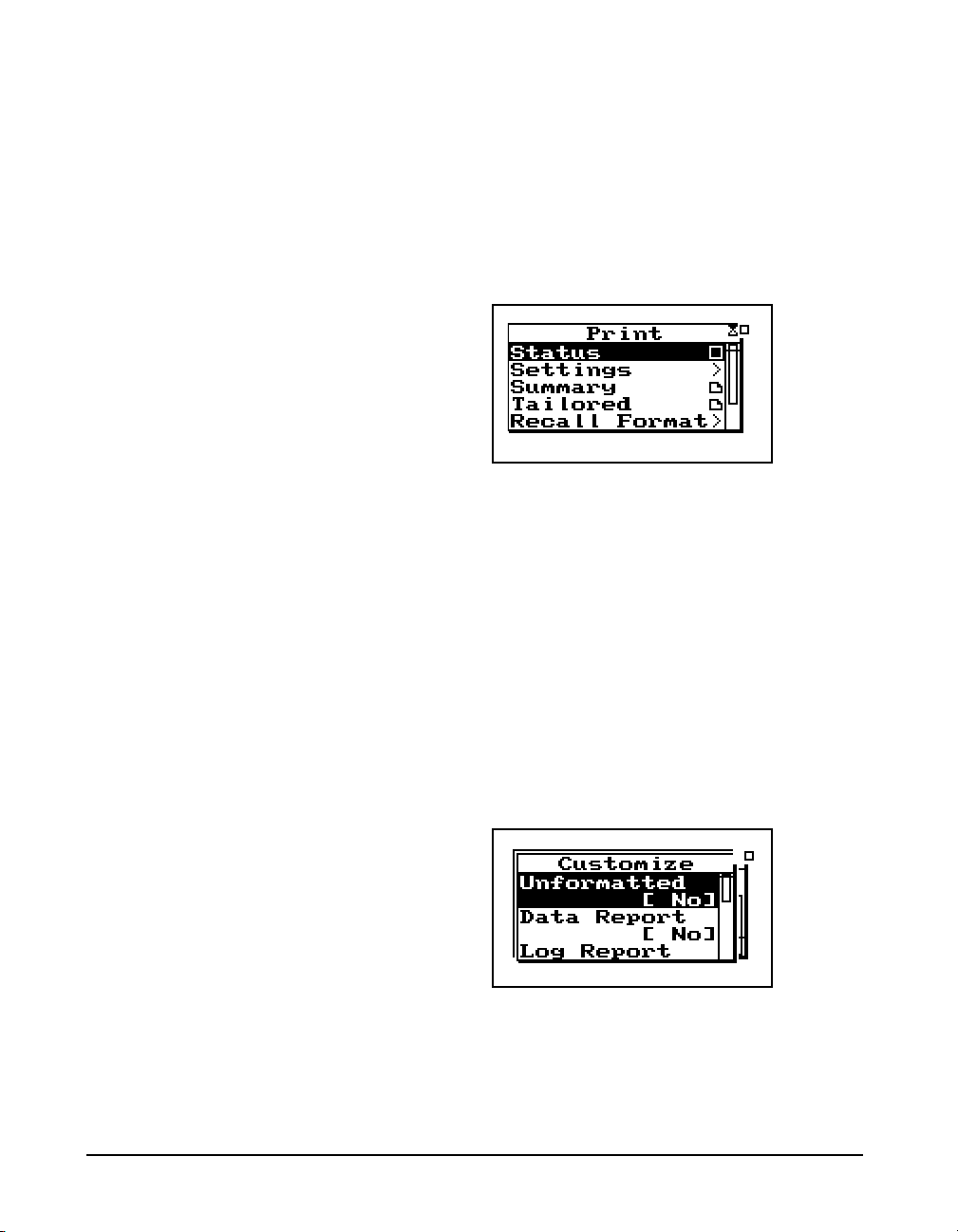
The Print menu changes depending
upon the specific instrument being
used.
ular data reports can also be printed on virtually any serial
printer.
The Print menu provides the ability to output reports containing all the data gathered for the measurement to an
attached printer. The main Print menu is activated by press-
ing the
With an appropriate printer connection, you can print a number of reports. The “Recall Format” sub-menu option is used
to enable various reports. Do this by highlighting the corresponding menu item and pressing the
Use “Tailored Report” to print the custom reports that are
defined as part of an instrument definition (SSA and LOG
IDs only).
P PRINT key.
c key.
Use the Customize sub-menu to further customize the report
settings. In this sub-menu you can select the specific elements to include in the report and also the various data
ranges for histograms, time histories, etc. To access this submenu, highlight Customize and press the
3-38 824 Reference Manual 9/29/09
r key.
Page 97

CHAPTER
4
Quick Start
The System 824 instrument provides simultaneous measurements of sound pressure level using Fast, Slow, Impulse,
Peak and Leq detectors with A, C, and Flat weighting covering a large dynamic range of greater than 105 dB in the LOG
and ISM instrument and 80 dB in SSA instrument.
With the System 824 calibrated, the desired instrument
definition selected, and its associated settings properly
configured, you can easily take a measurement and examine
the readings from the data collected. Taking an actual
measurement with the System 824 is as easy as pressing the
s (RUN/STOP) key.
This chapter helps users begin using the System 824
immediately. This chapter will present the following:
• Turning on and Calibrating the System 824
• Taking Measurements and Storing Data
• Recalling Stored Data
• Deleting Stored Data
• Selecting and Modifying Instrument Definitions (IDs)
Turning On and Calibrating the System 824
This section guides you through the process of turning on
and calibrating the System 824.
9/29/09 Quick Start 4-1
Page 98
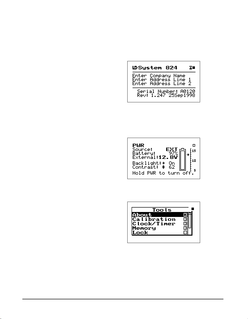
This screen displays three lines of
user information which may be
defined as name and address
settings. You can use the 824 Utility
Software to input this information.
This display also shows the serial
number of the instrument and the
firmware version and date. The
System 824 then loads the last
instrument definition (ID) selected.
Pressing the v POWER key for 1
second turns the power OFF.
Step 1 Turn on the System 824. To do this, press the
key (located on the left side of the key pad). By
pressing this key, the Larson Davis logo appears
while a number of tests are performed. The following screen then appears for a few seconds:
v
Power off prior to changing
microphone or preamplifier to avoid
possible damage of sensitive
electronics due to high voltage
spikes.
This screen shows you the current
power source, battery level, and
external power voltage.
Step 2 Check the battery level. After the System 824 is
turned on, you can check the battery level. To do
this, press the
following screen appears:
Step 3 Calibrate the instrument. To do this, press the
TOOLS key. The following menu appears:
v POWER key momentarily. The
T
4-2 824 Reference Manual 9/29/09
Page 99

Step 4 Using the dkey, highlight the Calibration
menu item, then press the
screen appears:
ckey. The following
NOTE: The output level specified by the
calibrator manufacturer will be at standard temperature and pressure. In practice the level is a function of temperature
and static (barometric) pressure, so a
corrected level should be used. Similarly,
the sensitivity of the microphone itself is
a function of temperature and static pressure. For directions on compensating for
temperature and static pressure during
calibration, see "Correction of Calibrator Output Level" on page 2-17.
Step 5 The value of Cal Level (3rd item on the screen)
must be set equal to the output level of the
calibrator to be used for the calibration (typically
94 or 114 dB). If the value indicated is not equal to
this value, use the
Level menu. Press the
and vertical arrow keys to input the correct value
and press the
Step 6 Place the calibrator over the microphone. Using
the
d key again, highlight the Change menu
item. Press the
process.
Step 7 When prompted by the message shown below,
press the
process. If you wish to abort the calibration
procedure,
press the
c key to continue the Calibration
c key.
d key to highlight the Cal
c key, use the horizontal
c key to make the change.
c key to start the Calibration
rarrow key to select Cancel and
Step 8 While the system is stabilizing, the measured level
is indicated on the left of the screen and the
difference between the measured level and the Cal
Level Setting are show on the left and right sides
9/29/09 Quick Start 4-3
Page 100
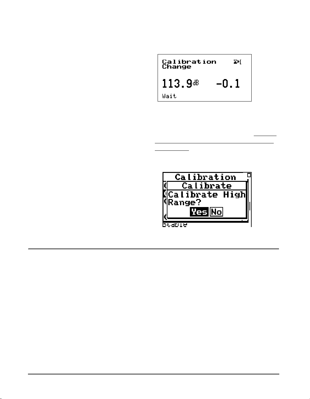
of the display, as shown below, along with the
message Wai t indicating that the calibration
process in underway and should not be interupted.
Step 9 When the calibration is complete, the message will
change to Stable, after which the following display
will appear to prompt the user to decide whether
or not to calibrate the High Range as well. If you
decide to calibrate the High range as well as the
Normal range, there will be a forty second delay
while the instrument stabilizes at the High range
setting.ll.
High Range Calibration
Note: When using a prepolarized
microphone, during setup Electret
should have been selected as the
Transducer. The High Range is not
available when using a prepolarized
microphone, so the prompt
concerning calibration of the High
Range will not appear.
4-4 824 Reference Manual 9/29/09
When the High Range is calibrated, the microphone bias
voltage is reduced from 200 to 20 volts. This reduces the
sensitivity of the microphone by 20 dB. As a result, the
measured level indicated on the left of the display during the
stabilization process should be 20 dB less than the Cal Level
value.
 Loading...