

Page 1
Model 2221
Microphone Preamplifier Power Supply
Technical Reference Manual
Page 2
Model 2221
Microphone Preamplifier
Power Supply
Technical Reference Manual
Larson Davis, a division of PCB Piezotronics, Inc.
1681 West 820 North
Provo, UT 84601-1341
24 Hour Hotline: (716) 926-8243
Toll Free (US): (888) 258-3222
www.LarsonDavis.com
I2221.01 Rev G
Page 3

Copyright
Copyright 2009 by PCB Piezotronics, Inc. This manual is copyrighted, with all rights
reserved. The manual may not be copied in whole or in part for any use without prior
written consent of PCB Piezotronics, Inc.
Disclaimer
The following paragraph does not apply in any state or country where such statements
are not agreeable with local law:
Even though PCB Piezotronics, Inc. has reviewed its documentation, PCB Piezotronics
Inc. makes no warranty or representation, either expressed or implied, with respect to
this software and documentation, its quality, performance, merchantability, or fitness
for a particular purpose. This documentation is subject to change without notice, and
should not be construed as a commitment or representation by PCB Piezotronics, Inc.
This publication may contain inaccuracies or typographical errors. PCB Piezotronics,
Inc. will periodically update the material for inclusion in new editions. Changes and
improvements to the information described in this manual may be made at any time
Equal Opportunity Employer
PCB Piezotronics, Inc. is an equal opportunity employer and does not discriminate on
the basis of race, color, religion, gender, national origin, disability or veteran status.
Please examine your instrument and record the following information below. You may
be asked to give this information in any future communications you have with PCB
Piezotronics, Inc.
Technical Support:
in the U.S. call toll-free: 888-258-3222
International customers:716-926-8243
FAX: 716-926-8215
Support@LarsonDavis.com
Worldwide Web: www.LarsonDavis.com
Page 4

Record of Serial Number and Purchase Date
Model 2221 Serial Number: ______________
Purchase Date: __________________
Recycling
PCB Piezotronics, Inc. is an environmentally friendly organization and encourages our
customers to be environmentally conscious. When this product reaches its end of life,
please recycle the product through a local recycling center or return the product to:
PCB Piezotronics, Inc.
Attn.: Recycling Coordinator
1681 West 820 North
Provo, Utah, USA 84601
where it will be accepted for disposal
Page 5

Table of Contents i-i
Table of Contents
Chapter 1 Introduction 1-1
About This Manual ........................................................1-1
Features........................................................................1-2
Unpacking and Inspection.............................................1-3
Accessories and Optional Equipment ...........................1-3
Chapter 2 Description 2-1
General Description ......................................................2-1
Connectors....................................................................2-3
Preamplifier Input................................................................................ 2-3
AC Output............................................................................................ 2-3
External DC Power Input .................................................................... 2-3
Controls.........................................................................2-4
Power ................................................................................................... 2-4
Microphone Bias Voltage.................................................................... 2-4
Gain ..................................................................................................... 2-4
Frequency Weighting .......................................................................... 2-4
Overload Reset .................................................................................... 2-4
LED Indicators ..............................................................2-5
Overload .............................................................................................. 2-5
Signal Present ...................................................................................... 2-5
External Power .................................................................................... 2-5
Battery Voltage.................................................................................... 2-5
Battery Compartment....................................................2-5
Chapter 3 Operation 3-1
Powering the Model 2221 .............................................3-1
Internal Battery Power.................................................................. 3-1
Battery Replacement............................................................................ 3-1
External Battery or DC Power ...................................................... 3-2
Cable Connections ....................................................................... 3-3
Signal Input Cable ............................................................................... 3-3
Page 6

i-ii Table of Contents:
AC Signal Output Cable.......................................................................3-3
Operation ..................................................................... 3-3
Switch On .....................................................................................3-3
Parameter Selection .....................................................................3-3
Microphone Bias Voltage.....................................................................3-4
Frequency Weighting ...........................................................................3-4
Gain ......................................................................................................3-4
Vernier Adjustment..............................................................................3-4
Gain Adjustment for Best Measurement .......................................3-5
Appendix A Technical Specifications A-1
Electrical Specifications ............................................... A-1
Input Impedance:.................................................................................A-1
Output Impedance ...............................................................................A-1
Preamplifier Supply............................................................................. A-1
Maximum Input Level.........................................................................A-1
Maximum Output Current...................................................................A-2
Overload Level (Input or Output) ....................................................... A-2
Output Slew Rate ................................................................................ A-2
Microphone Bias Voltage....................................................................A-2
Gain Settings ....................................................................................... A-2
Frequency Response................................................................... A-2
Output Noise................................................................................ A-3
Cable Driving Capability .............................................................. A-3
Indicators...................................................................... A-4
Overload..............................................................................................A-4
Output Signal....................................................................................... A-4
Battery Level.......................................................................................A-4
Power Supply............................................................... A-4
Battery Power......................................................................................A-4
Standby Performance .......................................................................... A-5
External 12 V battery or AC Adaptor ................................................. A-5
Mechanical................................................................... A-5
Dimensions .................................................................................. A-5
Height..................................................................................................A-5
Width................................................................................................... A-5
Page 7

Table of Contents i-iii
Length..................................................................................................A-5
Weight ..........................................................................................A-6
Connectors ...................................................................................A-6
Input.....................................................................................................A-6
Output ..................................................................................................A-6
Environmental .............................................................. A-7
Operating Temperature Range.............................................................A-7
Operating Humidity Range..................................................................A-7
Temperature Sensitivity.......................................................................A-7
Humidity Sensitivity............................................................................A-7
Electromagnetic Compatibility...................................... A-7
Europe.......................................................................................... A-7
United States................................................................................A-8
EMC Test Configurations .............................................................A-8
Page 8

ii-i
List of Figures
Introduction 1-1
Description 2-1
Model 2221............................................................................ 2-1
2221 Controls ........................................................................ 2-2
Operation 3-1
Accessing Battery Compartment ........................................... 3-2
Technical Specifications A- 1
Page 9

Introduction 1-1
CHAPTER
1
Introduction
Welcome to the Larson Davis Model 2221 Microphone
Preamplifier Power Supply. The Model 2221 provides
power for a microphone preamplifier, a microphone bias
voltage of 200 V for use with traditional air condenser
microphones (which can be switched off for use with
prepolarized microphones) and up to 50 dB of gain to
optimize the level of the output signal. It can be powered
by internal or external batteries or an external DC
voltage. It is characterized by low noise level and
distortion and the ability to drive very long cables, input
and output.
About This Manual
This manual has 3 chapters and 1 appendix covering the
following topics:
• Chapter 1 - Introduction: Orients the user to the
contents of this user manual and the features, functions
and measurement capabilities of the Model 2221. It also
includes instructions on unpacking the Model 2221.
• Chapter 2 - Description: Provides a physical
description of the Model 2221.
• Chapter 3 - Operation: Describes the setup and
operation of the Model 2221.
• Appendix A - Specifications: Presents the technical
specifications of the Model 2221.
Page 10

1-2 Features:
Features
The Larson Davis Model 2221 Microphone Power Supply
has the following features:
• Single Channel power and amplification for precision
microphone preamplifiers
• Internal batteries for portable operation
• 0 and 200 microphone bias voltages
• Selectable Flat (Z), A- and C-Weighting frequency
responses
• 0 to 50 dB gain range
• Last settings are saved even when not powered
• Both instantaneous and latched overload indications
• Output signal level indicating LED
• Internal battery voltage LEDs
• External power LED
• Ability to drive long input and output cables.
• Uses no power from internal or external batteries when
switched off.
• When powered by an external battery or DC voltage,
power will switch without interruption to the internal
batteries in the event of a power failure or when the
external DC voltage drops below the internal battery
voltage.
Page 11

Unpacking and Inspection: 1-3
Unpacking and Inspection
Your Model 2221 has been shipped in protective packaging.
Please verify the package contains the items listed below
and retain the shipping container for safe shipment at a
future date. Report any damage or shortage immediately to
Larson Davis, Inc. at 801 375-0177.
If you have not already done so, please record your
instrument’s serial number (located on the bottom of the
instrument) and the purchase date. You may be asked to give
this information in future communications with Larson
Davis.
Accessories and Optional Equipment
The Model 2221 delivered with the following standard
accessories:
• Six 1.5V AA Alkaline cells
• PSA017 115 Vac to 9Vdc 500 mA Power Adaptor
• Adjustment tool for use with vernier gain control
• User Manual (Larson Davis part number I2221.01)
• Calibration Certificate
The following optional equipment is also available:
• PRM902 and PRM903 1/2” Microphone Preamplifiers
• ADP008 1” microphone to 1/2” microphone preamplifier
adaptor
• ADP043 1/4” microphone to 1/2” microphone
preamplifier adaptor
Page 12

1-4 Accessories and Optional Equipment:
• EXAXXX Microphone Extension Cable, 7-pin LEMO
(the XXX indicates length in feet)
• CBL097 cable with 7-pin LEMO to BNC plug, 6’ long
• PRA951-2 and PRM951-4 Current Sources permitting
ICP
™ accelerometers to be used with the Model 2221.
• CAL200 and CAL250 Acoustic Calibrators
• PSA021 230Vac to 9Vdc 500 mA Power Adaptor
Page 13

Description 2-1
CHAPTER
2
Description
The physical description of the Model 2221 is presented
in this chapter. This includes a description of the front
panel keys and their functions, input and output
connectors, instrument controls and the functions of the
LED indicators. Operational information is presented in
Chapter 3 "Operation” on page 3-1
General Description
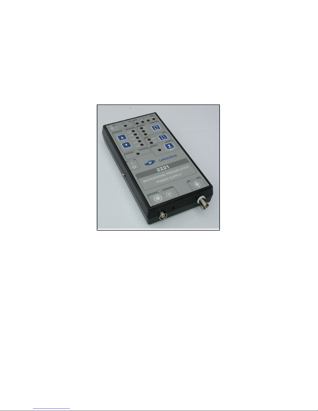
The Model 2221 has a flat shape factor with top panel
controls for optimal use on a table or desktop.
FIGURE 2-1 Model 2221
Page 14
2-2 General Description:
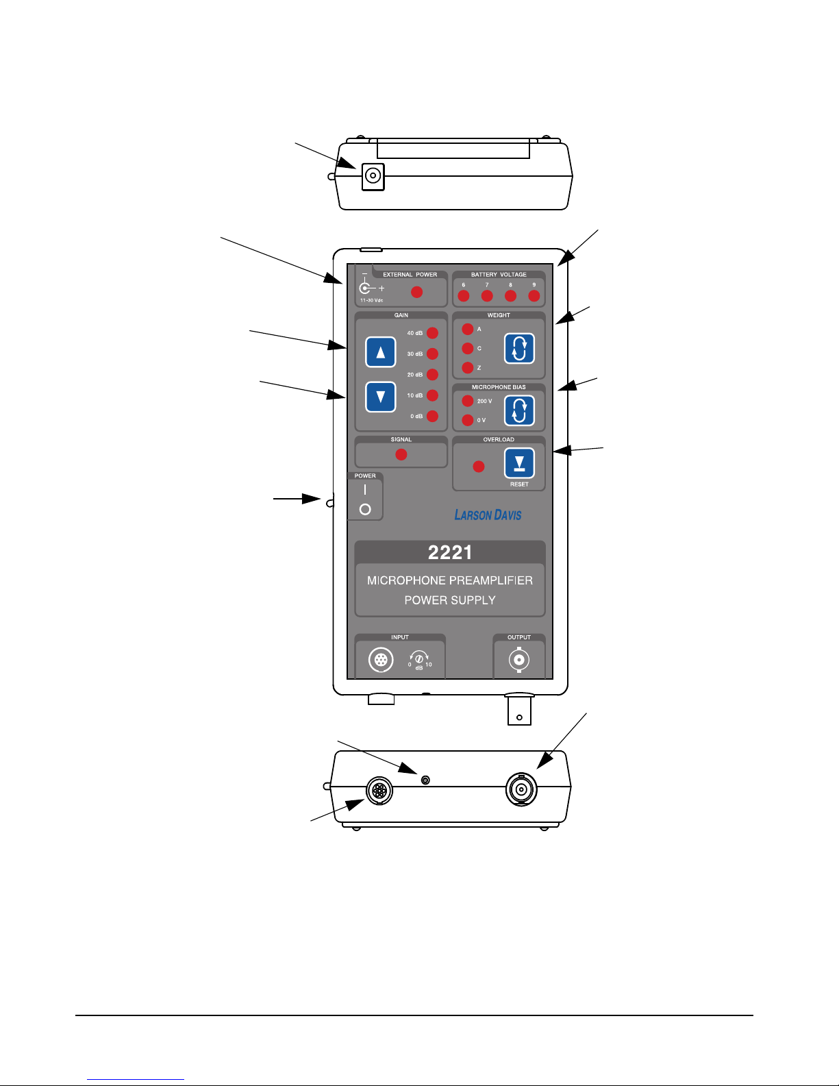
FIGURE 2-2 2221 Controls
On/Off
Switch
Increase
Gain
Decrease
Gain
Select Microphone
Bias Voltage
Reset Overload
AC Signal Output
Preamplifier Input
External Power Input
Select Frequency
External Power LED
Indicator
Weighting
Battery Voltage
LED Indicators
Vernier Gain Adjustment
Page 15

Connectors: 2-3
Connectors
Preamplifier Input
LEMO EPG.1B.307 7-pin Female
Pin Connections
AC Output
BNC Female
External DC Power Input
2.5 x 5.5 mm Coaxial Connector, center positive (External
DC voltage range: 10.5 to 30 V)
Pin Signal
1 No Connection
2 Signal Ground
3 Microphone Polarization Voltage
0 or 200 Volts
4 Signal Input
5 No Connection
6 Power Supply Positive Voltage
+ 18 Volts
7 Power Supply Negative Voltage
- 18 Volts
Shell Connected to Case ground
Page 16

2-4 Controls:
Controls
Power
Side mounted toggle switch
Back/On (
|)
Forward/Off (
Ο)
Microphone Bias Voltage
200 or 0 Volt, selection indicated by illuminated LED
Gain
0 to 40 dB in 10 dB steps, selection indicated by illuminated
LED
Note that there is also a 0 to 10 dB vernier gain (12 turn
potentiometer) adjustment at the front of the case.
Frequency Weighting
Choice of A, C or Z (Flat) Weighting, selection indicated by
illuminated LED
Overload Reset
Press button to reset latching overload
Page 17

LED Indicators: 2-5
LED Indicators
Overload
Flashing of the OVERLOAD LED indicates a steady input
overload. When the input voltage drops below the overload
level, the OVERLOAD LED will remain illuminated
(latched on) until reset.
Signal Present
The SIGNAL LED is illuminated when the output signal
exceeds 45 mV. The brightness will increase with the signal
level in a manner approximately proportional to the log of
the voltage.
External Power
The presence of an external voltage (10.5 - 30 Vdc) is
indicated by the illuminated EXTERNAL POWER LED
Battery Voltage
The internal battery voltage is indicated by the illumination
of one of the BATTERY VOLTAGE LEDs as indicated in
Table 2-2.
Battery Compartment
The Model 2221 is powered by six AA batteries. The battery
compartment is accessed from the bottom by removing the
LED
Battery Voltage
(Volts)
6 5.5 to 6.5
7 6.5 to 7.5
8 7.5 to 8.5
9 8.5 to 11.3
Page 18

2-6 Battery Compartment:
door as shown below. The battery polarity is indicated in the
bottom of the compartment.
Page 19

Operation 3-1
CHAPTER
3
Operation
This chapter presents a detailed description of the
operation of the Model 2221. This includes the methods
available for providing power, connecting input and
output cables, parameter selection and adjusting the
gain to obtain the best measurement.
Powering the Model 2221
The Model 2221 can be powered by internal batteries or
from an external DC power source such as the Larson Davis
PSA017, which is supplied as a standard accessory. No
internal or external power is used when the instrument is
switched off.
Internal Battery Power
The Model 2221 is designed to use six AA batteries. This
will provide 40 hours of continuous operation with the
PRM902 Microphone Preamplifier. To insert the batteries,
remove the battery compartment access door as shown in
FIGURE 3-1. The polarity is indicated in the bottom of the
battery compartment.
Battery Replacement
When replacing batteries, the manufacturer strongly
recommends that all cells be replaced with new ones of the
same capacity and type (e.g. all cells Alkaline, NiMH or
NiCd). Failure to do so could lead to cell leakage and
possible damage to the instrument.
Page 20

3-2 Powering the Model 2221
FIGURE 3-1 Accessing Battery Compartment
The internal battery voltage is indicated by one of four LEDs
as described in the section “External DC Power Input” on
page 2-3. If no LED is illuminated, the battery voltage is less
than 5.5 Volts.
External Battery or DC Power
Note: The internal batteries need not
be present to operate the Model
2221 under external DC power.
The Model 2221 can be powered by an external 12 Volt
battery or an AC/DC adaptor providing a voltage within the
range 10.5 to 30 Vdc.
Note: The PSA017 115 Vac to 9Vdc
500 mA power adaptor provided
with the Model 2221 provides
approximately 12 Volts when lightly
loaded by the 65 mA drawn by the
2221.
Power will switch without interruption to the internal
batteries when there is an external power failure or if the
external voltage drops below the internal battery voltage.
Page 21

Operation 3-3
Cable Connections
Signal Input Cable
Caution:Be sure that all connections
in the signal path are made prior to
turning on the system power.
Connect the microphone preamplifier cable to the 7-pin
LEMO connector on the front of the case. The length of the
cable will affect the frequency response of the system as
indicated in the section “Cable Driving Capability” on
page A-3.
To remove the cable, hold the connector collar between the
thumb and forefinger and pull.
AC Signal Output Cable
Connect the signal output cable to the BNC connector on the
front of the case.
Operation
Switch On
The power switch is on the left side of the case. Toggle it
backward to switch on the Model 2221 and forward to
switch it off. The Microphone Bias Voltage LED flashes for
40 seconds while the bias voltage stabilizes.
Parameter Selection
The measurement parameter settings of the Model 2221 are
saved two seconds after the last change, even when not
powered. Therefore, when switched on all measurement
parameters will be the same as when it was switched off.
Page 22

3-4 Operation
Microphone Bias Voltage
The bias voltage should be set to
zero when using a prepolarized
(electret) microphone and 200 V
when using a traditional air
condenser microphone.
The microphone bias voltage is either On, providing a
highly stable level of 200 Vdc, or Off. Pressing the
MICROPHONE BIAS key
will toggle the state between these two, When the bias
voltage selection is changed, the MICROPHONE BIAS
LED will flash for 40 seconds while the bias voltage
stabilizes.
Frequency Weighting
The input signal frequency weighting is selected by pressing
the WEIGHT key
Repeated presses will move the selection in the sequence Z
(Flat), C and A as indicated by the illuminated LED to the
left of the key. The characteristics of these weightings are
described in the section “Frequency Response” on page A-2
Gain
The input gain is set using the up and down arrow keys in
the front panel section entitled GAIN. The selected value is
indicated by the illuminated LED to the right of the arrow
keys.
Vernier Adjustment
Very fine gain adjustments can be made using the 12 turn
potentiometer located on the front end of the case to the right
of the signal input connector. This can increase the gain by
up to 10 dB by turning it clockwise using the adjustment tool
provided.
Page 23

Operation 3-5
Gain Adjustment for Best Measurement
The SIGNAL LED will be illuminated when the input signal
level is above 45 mV. The higher the level, the brighter the
LED will be. When measuring fairly stable signals, it is
recommended to increase the gain until an overload is
indicated, reduce the gain by 10 dB and reset the latching
overload. If no further overloading is indicated, this should
be a good setting.
If using the Model 2221 for repeatable non-steady signals,
such as recording the output during a machine cycle, it is
recommended to make several test runs in order to find the
highest gain setting which does not produce an overload
during the complete measurement period.
Page 24

Technical Specifications A-1
APPENDIX
A
Technical Specifications
The technical specifications in this chapter are subject to
change without notice. Please refer to calibration and test
results for data on a specific unit.
Electrical Specifications
All values are given at 20 °C, 50% R.H., 12 V external supply, < 3 m (10’) cable and a direct input
from a 50 Ohm generator unless otherwise specified.
Input Impedance:
Output Impedance
50 Ohm
Preamplifier Supply
± 18 Volts
Maximum Input Level
18 Volt, Peak
Frequency A-Weight C- and Z-Weight
100 Hz 169 kOhm 39 kOhm
1 kHz 34 kOhm 28 kOhm
10 kHz 28 kOhm 28 kOhm
Page 25

A-2 Electrical Specifications
Maximum Output Current
25 mA
Overload Level (Input or Output)
Positive and negative overload detection: ± 16.5 Volt Peak
Output Slew Rate
10 Volt/μS
Microphone Bias Voltage
0 and 200 Volt (± 0.25 V
)
Note: LED flashes for 40 seconds while microphone bias voltage is stabilizing
Gain Settings
0 to 40 dB in 10 dB steps
0 to 11 dB vernier gain (12 turn potentiometer)
Error with vernier fully counter-clockwise
< 0.1 dB to 20 dB
< 0.2 dB to 40 dB
Frequency Response
.
Weighting Specification
A- and C-Weight IEC 60651 (2001) and ANSI S1.4 (R 2001)
“Sound Level Meters” Type 0
A-, C- and Z-Weight IEC 61672-1 (2002) “Sound Level Meters”
Class 1
Page 26

Electrical Specifications A-3
Output Noise
The output noise is measured over the frequency range 20 Hz to 20 kHz, with the input shorted.
Cable Driving Capability
The values presented below correspond to a cable having a
capacitance of 30 pF/ft.
A-Weight 63 Hz to 20 kHz (± 0.3 dB)
10 Hz to 50 Hz (± 0.7 dB)
C-Weight 25 Hz to 20 kHz (± 0.3 dB)
10 Hz to 20 Hz (± 0.6 dB)
Flat (Z-Weight) 10 Hz to 100 kHz (± 0.2 dB)
1 Hz to 150 kHz (-3 dB)
Gain Flat (Z-Weighting) A-Weighting C-Weighting
01.9μV5.9μV4.4μV
10 3.7μV8.6μV5.0μV
20 7.8μV20μV6.6μV
30 25μV64μV21μV
40 77μV 200μV64μV
Length, feet 14 Vpeak 4.2 Vpeak 1.4 Vpeak
250 38 kHz 120 kHz 300 kHz
500 19 kHz 62 kHz 180 kHz
Page 27

A-4 Indicators
Indicators
Overload
Instantaneous (Blinking LED)
Latched (Steady LED) - Reset on Keypad
Output Signal
LED illuminated for output signals > 45 mV
Battery Level
Power Supply
Battery Power
Six AA batteries
40 hours of continuous operation with the PRM902 Microphone Preamplifier
1,000 9.5 kHz 31 kHz 92 kHz
2,000 4.7 kHz 15.6 kHz 47 kHz
Length, feet 14 Vpeak 4.2 Vpeak 1.4 Vpeak
LED
Battery Voltage
(Volts)
6 5.5 to 6.5
7 6.5 to 7.5
8 7.5 to 8.5
9 8.5 to 11.3
Page 28

Mechanical A-5
Battery level indicator (4 LEDs)
Standby Performance
Uses no power from internal or external batteries when switched off.
External 12 V battery or AC
Adaptor
External DC Voltage Range: 10.5 to 30 V
Note: The Model 2221 will run on
external DC voltage down to 6 Volts,
but will draw power from whichever
supply (external or internal battery)
has the highest voltage.
Current: 65 mA @ 12 V with PRM902 Microphone Preamplifier
2.5 x 5.5 mm coaxial connector, center positive
Power switches (without interruption) to the internal batteries when there is an external power failure
or low external voltage.
Mechanical
Dimensions
Height
32.8 mm (1.29 in)
Width
104 mm (4.10 in)
Length
204 mm (8.02 in)
Page 29

A-6 Mechanical
Weight
425 grams (15 oz.) with six AA cells
Connectors
Input
LEMO EPG.1B.307 7-pin Female
Pin Connections
Output
BNC Female
Pin Signal
1 No Connection
2 Signal Ground
3 Microphone Polarization Voltage
0 or 200 Volts
4 Signal Input
5 No Connection
6 Power Supply Positive Voltage
+ 18 Volts
7 Power Supply Negative Voltage
- 18 Volts
Shell Connected to Case ground
Page 30

Environmental A-7
Environmental
Operating Temperature Range
- 40 to + 60 °C (- 40 to +140 °F)
Operating Humidity Range
0 to 90% RH non-condensing
Temperature Sensitivity
<± 0.03 dB
@ 1 kHz from - 40 to + 60 °C (- 40 to +140 °F)
Humidity Sensitivity
<± 0.03 dB
@ 1 kHz from 0 to 90% RH non-condensing at 40 °C (104 °F)
Electromagnetic Compatibility
Europe
The Model 2221 complies with the European Community EMC Directive (2004/108/EC) and also the
Low Voltage Safety Directive (2006/95/EC) by meeting the following standards:
• IEC61326-1:2005: Electrical equipment for measurement, control and laboratory use - EMC
requirements.
•IEC61000-4-2:2008 Electrostatic discharge (ESD) immunity.
± 4kV contact discharges and
± 8 kV air discharges.
•IEC61000-4-3:2006 Radiated, radio frequency, electromagnetic field immunity. 26 MHz to 1
GHz at 10 V/m, 1.4 GHz to 2 GHzat 3 V/m, 2.0 GHz to 2.7 GHz at 1 V/m with 1 kHz 80%
AM.
•IEC61000-4-4:2004 Electrical fast transient (EFT)/burst immunity.
±2 kV (5/50 ns, 5 kHz).
Page 31

A-8 Electromagnetic Compatibility
•IEC61000-4-6:2008 Immunity to RF conducted line disturbances. 10 V, 1 kHz 80% AM from
150 kHz to 80 MHz.
•IEC61000-4-8:2001 Power frequency magnetic field immunity. 80 A/m. 50/60 Hz.
•CISPR 11:2009: Industrial, scientific and medical (ISM) radio-frequency equipment - Electromagnetic disturbance characteristics - Limits and methods of measuremen.t Class B
• IEC61010-1:2001 Safety requirements for electrical equipment for measurement, control and laboratory use - Part 1: General Requirements.
United States
In the United States of America, the Model 2221 complies with he FCC Part 15 regulations as follows:
• Conducted and Radiated Emissions meet Class B limits.
EMC Test Configurations
The Model 2221 was tested with 40 dB Gain, Z weight and with the microphone bias set to 200V.
The reference orientation is with the microphone facing the emissions/immunity antenna.
The following accessories are connected during testing: 2559 microphone, PRM902 preamplifier,
EXA010, and External power from a PSA017 AC to DC power adapter.
The setting and configuration for greatest radio-frequency emissions and mode of operation that
produce minimum immunity to power-and radio-frequency fields is Z weight, 40 dB Gain with all of
the accessories listed above connected.
No degradation in performance or loss of functionality was found following the application of
electrostatic discharges.
The method of mounting the instrument for acoustic testing is with the microphone on a tripod.
Page 32

Index
A
Accessories .................................................................................................................................. 1-3
B
Battery
Compartment ........................................................................................................................ 2-5
External................................................................................................................................. 3-2
Internal.................................................................................................................................. 3-1
Replacement ......................................................................................................................... 3-1
C
Cable Connections
AC Signal Output ................................................................................................................. 3-3
Signal Input........................................................................................................................... 3-3
Connectors ................................................................................................................................... 2-3
AC Output............................................................................................................................. 2-3
External DC Power...............................................................................................................2-3
Preamplifier Input................................................................................................................. 2-3
Controls........................................................................................................................................ 2-4
Frequency Weighting............................................................................................................ 2-4
Gain....................................................................................................................................... 2-4
Microphone Bias Voltage ..................................................................................................... 2-4
Overload Reset...................................................................................................................... 2-4
Power .................................................................................................................................... 2-4
Customer Service.......................................................................................................................... i-2
E
Electromagnetic Compatibility ...................................................................................................A-8
Environmental Specifications ..................................................................................................... A-7
F
Features........................................................................................................................................ 1-2
Frequency Weighting............................................................................................................. 2-4,3-4
G
Gain.............................................................................................................................................. 2-4
Selection ............................................................................................................................... 3-4
Vernier Adjustment ..............................................................................................................3-4
Page 33

I
Indicators ............................................................................................................................. A-3,A-4
Inspection..................................................................................................................................... 1-3
L
LED Indicators............................................................................................................................. 2-5
Battery Voltage..................................................................................................................... 2-5
External Power...................................................................................................................... 2-5
Overload ............................................................................................................................... 2-5
Signal Present ....................................................................................................................... 2-5
M
Microphone
Bias Voltage....................................................................................................................2-4,3-4
O
Overload
Flashing................................................................................................................................. 2-5
Reset ..................................................................................................................................... 2-4
Steady ................................................................................................................................... 2-5
P
Parameter Selection ..................................................................................................................... 3-3
Frequency Weighting............................................................................................................ 3-4
Gain....................................................................................................................................... 3-4
Microphone Bias Voltage ..................................................................................................... 3-4
Power ........................................................................................................................................... 3-1
External AC/DC Adaptor ..................................................................................................... 3-2
External Battery.................................................................................................................... 3-2
Internal Battery ..................................................................................................................... 3-1
On/Off................................................................................................................................... 3-3
Switch ................................................................................................................................... 2-4
S
Specifications
Electrical .............................................................................................................................. A-1
EM ....................................................................................................................................... A-8
Indicators ...................................................................................................................... A-3,A-4
Mechanical........................................................................................................................... A-5
Power Supply....................................................................................................................... A-4
Page 34

T
Technical Support ......................................................................................................................... i-2
U
Unpacking.................................................................................................................................... 1-3
Page 35

Total Customer Satisfaction Guaranteed
3425 Walden Avenue, Depew NY USA 14043
Phone: 716-926-8243 Toll Free: 888-258-3222
LarsonDavis.com FAX: 716-926-8215
 Loading...