

A
B
C
A
C
A
A
B
B
H
INGE SIDE
Z
-BAR
TOP Z-BAR OR DRIP CAP
E
XPANDER AND
V
INYL SWEEP
L
ATCH SIDE
Z-BAR
P
INCH
PINCH
PINCH
PINCH
PINCH
PINCH
CAUTION
INSTALLATION
QUESTIONS?
MISSING PARTS?
PLEASE CALL
1-888-483-3768
OR VISIT
www.larsondoors.com
202220566
EASYVENT LM 10/04
™
EasyVent
Storm/Screen Doors
INSTALLATION INSTRUCTIONS
Congratulations on your new storm door. Your satisfaction is Larson’s number one priority. If you need
assistance or parts, please call the Lar
READ BEFORE BEGINNING INSTALLATION
• Read installation instructions thoroughly.
• Use two people when lifting and installing the door.
• Children should not be allowed to play with the door.
• Homeowners should be aware of pinch points.
• Failure to install door properly could result in an injury.
• Do not operate the storm door without closer(s) installed
and adjusted to prevent door slamming.
• Eye protection must be used during the installation to
prevent injury from flying particles.
• Do not modify or alter the installation and specified use
of the door.
• After installation, clean door with mild soap and water to
remove any oil or dirt residue.
• Larson Manufacturing is not responsible for accidents
and injury resulting from the use or installation of this
product.
son hotline or visit our website.
TOOLS NEEDED:
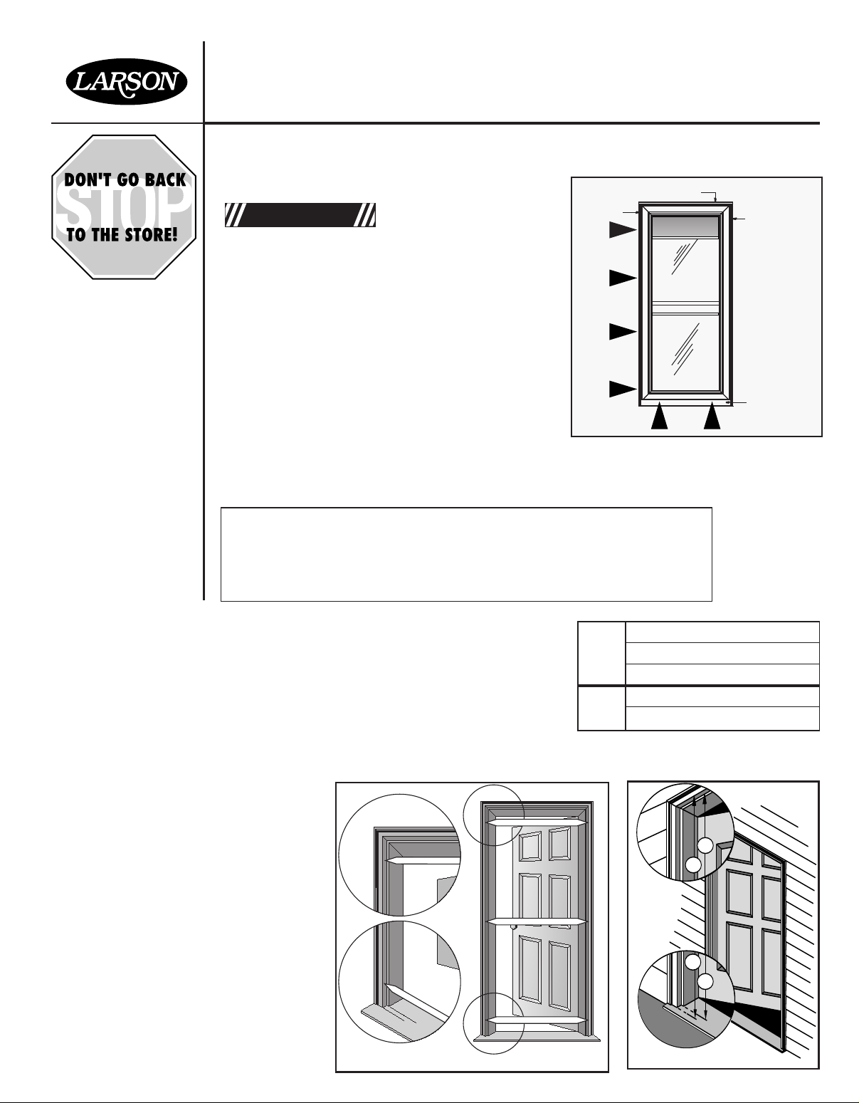
STEP 1
Record Opening
Measurements
Power drill with assorted bits
Phillips head screwdriver
Regular screwdriver
Hacksaw
Caulking gun with caulking
Tape measure
Hammer
Pencil
Pliers
Before starting, measure the opening width and height and
record measurements. Verify minimum and maximum width
allowance shown on box label to ensure you have purchased
the correct size storm door.
NOTE: Measure height from the top of the door opening
(underside of the trim board) down to the bottom threshold.
o measurements as sho
e tw
ak
T
wn in Figure 2 to determine
the threshold angle. You will need this information as you
install the hinge z-bar.
Saw horses
Small wood chisel
1
2
Width A
Width B
Width C
Height A
Height B
FIGURE
FIGURE
FIGURE 1
FIGURE 2
L
EFT HAND HINGE
RIGHT HAND HINGE
#8H/10B x 1/2" Flathead U.C.
TOP OF DOOR
INSIDE FACE OF DOOR UP
INSTALLED
POSITION
ROTATE
START
SCREWDRIVER
WITH
LONG SHAFT
INSIDE LIP
HINGE LEAF
TURNED UP
STEP 2
MORTISE
HOLE
COVER
3/32" PILOT HOLE @2
#6 x 5/8" FLATHEAD SCREW
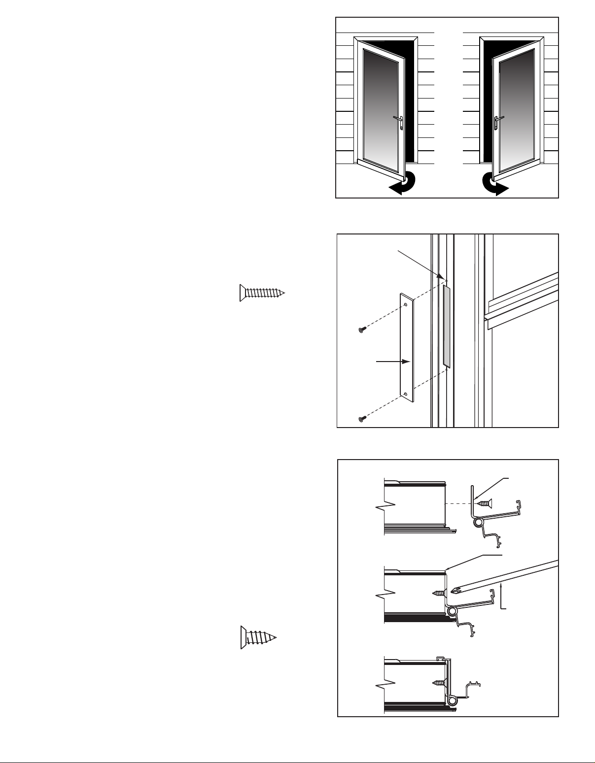
Determine Left
or Right Hinge
Side
STEP 2a
Install Mor
Hole Cover
tise
Your Larson storm door is REVERSA-HINGE
meaning that the door is designed for either right
hand or left hand hinge installation. Looking at your
door opening from the outside, determine which
side you want the hinge attached. The hinge can be
mounted to either side of the door (Figure 3).
IMPORTANT NOTICE: If you choose to have the
storm door handle on the same side as your
prime door hardware, you MUST verify that
there will be NO interference between the two
handles or hardware.
Your storm door handle will be 39" down from the
top of the opening. If the prime door hardware is at
this height, it is likely to interfere with the storm door
hardware. If this is the case, we recommend you
hinge your storm door opposite your prime door.
FIGURE 3
Install Mortise Hole Cover to the hinge-side of your
door frame (Figure 4) using #6 x 5/8" flathead
screws. The opposite side will be left open for
handle installation in Step 12.
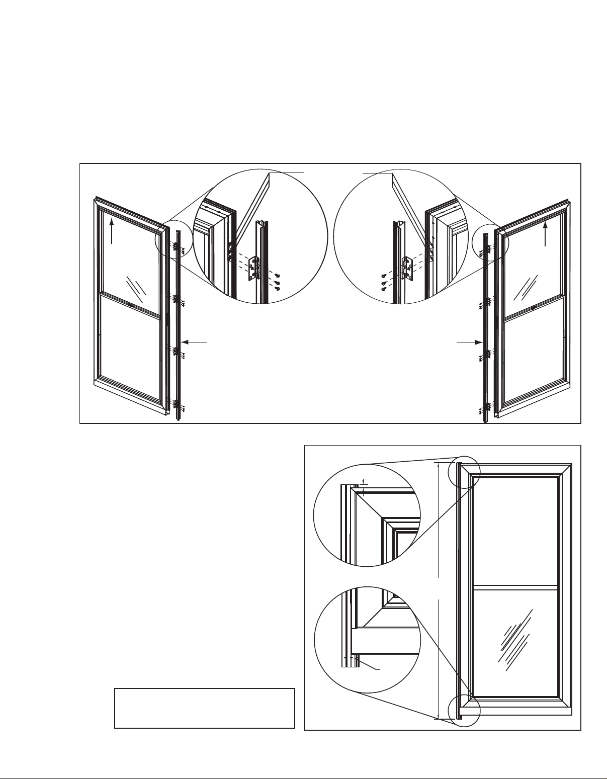
Install Hinge
STEP 3
on Door
The hinged z-bar assembly identified in Figure 6 is
packaged unattached. It can be mounted to either
side of the door.
Lay door flat on saw horses with outside face down.
Place the hinge z-bar assembly on the edge of the
door as shown with each hinge leaf turned up
(Figure 5). Check to see that the aluminum z-bar is
orientated as shown in figure 6 (next page), taking
into consideration if you want left or right hinging.
IMPORTANT: Move hinge z-bar assembly until
the top of the z-bar hangs over the top edge of
the door 1/4"
(Figure 7). Align the edge of the top
hinge against the lip on the inside edge of the door
(Figure 5). Mark hole and drill a 1/8" pilot hole.
Fasten with one screw using a #8h/10b x 1/2" flat
head screw.
with a long shaft due to the difficult angle of the
z-bar or door will not operate properly
Note: You must use a screwdriver
.
Repeat this procedure for the remaining hinges
making sure edge of hinge is lined up against the
inside lip (Figure 5). Drill pilot holes for remaining
holes and insert the screws.
NOTE: Hinged z-bar must swing freely (no
binding) after securing hinges to the door
.
FIGURE 4
2 EASY VENT 202220566
FIGURE 5
INSIDE FACE
RIGHT HINGE INSTALLATION
1/8" PILOT HOLES
REQUIRED
HINGED
Z-BAR
Make sure cassette that houses screen
is at the top of door
SCREEN
CASSETTE
TOP OF DOOR
LEFT HINGE INST
ALLATION
HINGED
Z-BAR
SCREEN
CASSETTE
INSIDE FACE
INSIDE
OF
DOOR
SHOWN
INSIDE
OF
DOOR
SHOWN
CUT
LINE
OPENING
HEIGHT
1/4"
OVERHANG
FRONT
OF
DOOR
STEP 4
Cut Hinge-Side
Z-bar to Length
The top of the Z-bar should be installed at the correct
position—a minimum of 1/4" above the door
. The bottom of
the Z-bar must be cut to the correct length (opening height),
taking into account the angle of the threshold. Refer to Figure
2.
• Using the measurements taken in Step 1, determine the
angle to cut the Z-bar. Transfer this measurement to the Zbar. Do NOT cut on the mark.
• Make the cut 1/16" less than your measurement to allow
room for the top drip cap. Save the z-bar cut-of
f scrap for
securing door to opening (step 6).
HINT: Measure twice.
Cut once!
FIGURE 6
FIGURE 7
202220566 EASY VENT 3

#8 x 1" FLATHEAD SCREW
#8 x 1" PANHEAD SCREW
R
UBBER SWEEP
OUTER FACE OF DOOR
CRIMP INNER LEG
EXPANDER
INSTALLED POSITION
WOOD
SPACER
SPACER MAY BE
REQUIRED IF DISTANCE
IS GREATER THAN 1/4"
1/8" IS IDEAL
SCRAP Z-BAR
INSERT STILES
STORM DOOR
MASTERFRAME STILE
BRICKMOLD
TOP VIEW:
HORIZONTAL SECTION
APPROX. ALIGNED
STEP 5
#8 x 1" PANHEAD SCREW
Install Expander
Sweep
STEP 6
Secure Door to
Opening
To install sweep, thread the sweep into the channel of the
expander (Figure 8). With the sweep installed, crimp both
ends of the expander channel with pliers.
NOTE: For best
results crimp the inner leg of the channel – only at both
ends of the expander
. You must bend the rubber sweep
out of the way while crimping. Install expander on door.
Do NOT fasten at this point. Adjust and fasten the expander
after the door is completely installed (Step 11).
• Place the door in the opening with the hinge-side Z-bar
tight against the door brickmold. Install just two of the
painted #8x1" pan head screws on the front of the hingeside Z-bar. Install one screw next to the top hinge and one
next to the bottom hinge. Be sure not to over tighten the
screws and crush down the Z-bar.
• To ensure proper clearance, set the cut-off scrap piece of
Z-bar in place between the door and up against the wood
trim on the latch side of the door (Figure 10).
• From the outside of the house with the door closed, check
the distance between the side of your Larson storm door
and the scrap Z-bar. If this distance is greater than 1/4",
a wood spacer can be placed between the hinge or latchside Z-bar and the wood jamb (Figure 9).
FIGURE 8
STEP 7
Secure
Hinge-Side
Z-Bar
• If a wood spacer is needed, remove the door, add the
spacer and reinstall. Spacer thickness should NOT
exceed 1/4" and longer screws should be used to properly
secure the door to the jamb. (A wood spacer can also be
used on the latch side Z-bar.)
NOTE: Wood spacers and
longer screws are not included.
FIGURE 9
ith the door properly fit in the opening, open the door to
W
•
expose the hinges. You will see two (2) pre-punched
holes at each hinge plate.
• Using eight (8) #8x1"
hinge plate to the wood jamb. Screw heads must be
flush with the hinge surface.
• Install the remaining #8x1" painted
the outside of the hinge-side Z-bar
FLAT head screws, attach each
PAN head screws in
.
FIGURE 10
4 EASY VENT 202220566

TOP Z-BAR (DRIP CAP)
INSTALLED POSITION
HINGE
Z-BAR
SHOWN
HINGE Z-BAR
VINYL SCREW COVER
LATCH
Z-BAR
SCREW
COVER
O
PENING HEIGHT
(
UNDERSIDE OF
D
RIP CAP TO
TOP OF SILL)
TOP OF DOOR CUT AWAY VIEW
TOP OF FRAMED OPENING
DOOR WILL NOT OPEN IF
THIS IS LESS THAN 1/4"
M
ASTERFRAME
H
EAD
D
RIP CAP
C
AULK
STEP 8
Install the
Drip Cap
The drip cap goes above the door and z-bars. Place the
top drip cap into position as shown in Figure 11. Close the
door. The drip cap and z-bar should nest together for a
good fit. Make sure door closes freely without hitting the
dripcap, but also makes good contact with the
weatherstripping.
pan head screws provided.
OF DRIPCAP
Attach the drip cap with #8x1" painted
CAULK ALONG TOP EDGE
.
STEP 9
Latch-Side
STEP 10
Install Screw
Cap Covers
Install
Z-Bar
Determine Top:
First, determine which end of the Zbar is the top and mark it with a
piece of tape.
Bottom Cut:
Cut the Z-bar to length, using the
same procedure used to cut the
hinge side Z-bar in Step 4. Allow
1/16" for top drip cap (Figure 12).
Installation: Set the Z-bar in place
between the door and the wood
jamb. Allow a 1/8"-3/16" gap
between the door and the latch-side
Z-bar. Make sure the door closes
freely without hitting the Z-bar, but
also makes good contact with the
weatherstripping. See Figure #10
for approximate z-bar to edge-ofdoor alignment. Fasten Z-bar using
#8x1" painted pan head screws
through pre-drilled holes provided in
Z-bar.
• After the door is installed, apply
the drip cap screw cover. Attach
this part per Figure 13. Start at
one end, snap the cover on
working your way towards the
other end.
NOTE: Be sure to
insert the edge toward the door
first, then snap in outer edge.
• Cut the latch and hinge z-bar
screw covers to length—matching
the z-bar lengths respectively.
NOTE: Cut covers using a
scissors or a tin snips.
FIGURE 11
FIGURE 12
• Attach the latch and hinge z-bar
screw covers per Figure 12 as
described above.
FIGURE 13
202220566 EASY VENT 5

#
6 x 3/8" PANHEAD STAINLESS
STEP 11
#
6 x 5/8" FLATHEAD SCREW
Remove
otective Tape
Pr
and
Adjust Bottom
Expander
STEP 12
Install Latch and
Strike Hardware
Some door models have a protective tape over the
door frame on both outside and the inside surface.
Remove this tape now.
Adjust the bottom expander so that the vinyl sweeps
touch the door threshold.
expander should be located on the inside of the door.
Centrally locate the two #6 x 3/8" pan head screws in
the slot to allow for future adjustments.
Drill 3/32" diameter pilot holes for the screws, being
careful not to drill all the way through to the front face
of the door.
screws will break!
Refer to separate instructions packaged in the
hardware box.
NOTE: Pilot holes must be drilled or
The slotted holes in the
STEP 13
Glass Sash/
Screen
Operation
This door has a retractable screen located in the
masterframe head.
• To ventilate make sure sash lock is unlocked, then
pull down on top insert.
• To close, push up on the insert.
• If the screen comes out of the track, it should be
pushed back in place before retracting or simply
close the insert and the screen will reposition itself.
• Use the sash lock to secure the top insert in place.
NOTE: Slow, steady operation should be used to
open and close screen.
6 EASY VENT 202220566

#10 X 5/8" SCREW
SHORT PIN
LONG PIN
#10 x 1-1/2" ROUND HEAD
HINGE SIDE JAMB
#10 X 1 1/2" SCREWS
SHORT CONNECTING
PIN
BOTTOM CLOSER
SASH LOCK
LONG CONNECTION PIN
TYP.
1"
DOOR BRACKET
TOP CLOSURE
SIDE JAMB BRACKET
1/4" FROM DOOR
C
LOSER
FLANGE
E
XTEND ROD 1/4" OUT
“
HOLD OPEN” WASHER
1/4"
EasyVent Series Storm/Screen Door
CLOSER INSTRUCTIONS
NOTE: Be sure door opens and closes freely
before installing the closer.
STEP 1
Closer
Installation
CLOSER ASSEMBLY PREPARATION
• Slide hold-open washer onto closer rod as shown.
Pull rod out of closer so that there is approximately
a 1/4" gap per Figure 1 (insert small screwdriver in
rod hole to provide pulling grip). Position washer
behind flanges and against the closer.
screwdriver.
This will give proper tension for
installation. (Do not change until installation is
complete.) See Figure 1.
• Attach brackets to closer as shown in Figure 2.
Attach
front hole in closer to door bracket (long
connecting pin). Attach closer rod to side jamb
bracket (
short connecting pin) with open side of
jamb bracket toward storm door (see arrow on
bracket).
Your closer assembly is now ready to
be attached to inside of door.
• Close and latch door.
FIGURE 2
Remove
FIGURE 1
202220566 EASY VENT 7

FRONT HOLE
REAR HOLE
ADJUSTING SCREW
CLOSER
SILL DETAIL
CLOSER BRACKET
CAUTION:
TO AVOID SCREEN DAMAGE,
DO NOT ATTACH BRACKET IN THIS AREA!!!
CLOSER BRACKET
TOP OF
WOOD
FRAMING
SCREEN
TUBE
SILL
DRIP
CAP
BRASS
EXPANDER
INTERIOR
HEAD DETAIL: TOP CUTAWAY
SILL DETAIL: BOTTOM CUTAWAY
EXTERIOR
STEP 2
#10 X 5/8" SCREW
SHORT PIN
LONG PIN
#10 x 1-1/2" ROUND HEAD
Closer
Assembly
Installation
• To install the top closer, position door bracket as
shown in Figure 2 and Figure 3. Slide closer over
until jamb bracket is 1/4" back from storm door.
Mark jamb bracket holes and two holes in door
bracket.
• Fasten jamb bracket to jamb with four #10x1-1/2"
screws. The
should be toward the storm door (
bracket
Close and latch the door. Hold the closer and
•
open side of the jamb bracket
see arrow on
).
door bracket level and mark the location for the
insertion of the door bracket screws. Drill 1/8"
starter holes.
the outside of door.
CAUTION: Do not drill through
Install two #10 x 5/8"
screws in bracket.
• To install bottom closer, refer to Figure 2 and
Figure 3 for placement and repeat steps used to
install top closer.
NOTE: Bottom closer may need
to be applied over the door expander in some
cases.
Do not fasten door bracket to kick plate
on mid-view models. Bracket must be in
position as shown in Figure 3.
• To hold the door open: Open door. Slide holdopen washer over flanges toward cylinder on
closer.
FIGURE 3
STEP 3
Controlled
Latching Power
Feature
the FRONT hole of closer, the door will accelerate
its closing speed in the last few inches of travel.
This attachment position is recommended when the
glass storm panel is in place.
If a smoother, quieter closing action is desired, hold
door open about 8" with hold-open washer. Move in
from door bracket and relocate in closer REAR
Installed as directed, with door bracket connected to
hole.
Adjust each closer individually (with the other
closer disconnected from the door) to the closing
speed suf
for each closer should be the same.
ficient to latch the door
The closing speed
.
FIGURE 4
To change closing speed, turn screw on
the end of closer tube clockwise for
slower and counter clockwise for faster
See Troubleshooting, Symptom D for
more adjustment information.
8 EASY VENT 202220566

Storm Door General Care and Maintenance
Keep this document along with your Installation Instructions for future reference.
Glass W
Door Finish Aluminum Skin—Non-abrasive paste wax may be used on your door’s outer surface to help keep the
Hinges/Hardware Hinges and door hardware may require occasional lubrication. A silicone spray lubricant is recommended.
Brass-tone Expander Wash expander using a warm water/mild detergent mixture, and a soft cloth. Do not use a brass cleaner
(Anodized) or steel w
ash glass using a household glass cleaner, or a warm water/mild detergent mixture, and a soft cloth or
wel.
paper to
finish looking new.
ool.
(Follow directions on the product’s label.)
Brass Products (Finish)
Select Larson storm door models incorporate high quality “real" brass component parts. As with all brass products, tarnishing will
occur. Without proper care, brass can become heavily stained, and in extreme cases of neglect, pitting can occur. Larson locksets and
deadbolts have a clear coat finish to protect against tarnishing. If the clear coat finish is damaged, tarnishing will occur. Larson brass,
inlaid in the glass, does not have a clear coat finish. It requires periodic cleaning and polishing to maintain the shiny brass
appearance. Should tarnishing occur in either case, the shiny brass finish can be restored as follows:
Brass Locksets, Deadbolts, Name Plates
• Cleaning
1. Wash brass hardware using a warm water/mild detergent mixture, and a soft cloth. Do not use abrasive cleaners or cloths as
they may damage the clear coat finish.
2. Apply non-abrasive paste wax on the brass hardware to help restore it’s bright finish.
• Refinishing (if clear coat is damaged and tarnishing has occurred)
1. Remove the tarnished hardware from the door.
2. Remove damaged clear coat. This can be done by using a paint stripper, or by lightly rubbing the hardware using #0000
steel wool. Follow the manufacturer’s instructions when using a stripper. Note: If refinishing keyed hardware, cover the
key opening with masking tape to keep out stripper or steel wool particles.
3.Once the clear coat is removed, continue to lightly rub with #0000 steel wool over tarnished areas until the bright brass
finish returns.
4. Clean the brass using a brass cleaner (i.e. Brasso, Tarni-Shield) per the manufacturer’s directions.
5. Apply a “new” clear coat finish. For best results, a clear lacquer spray is recommended. The lacquer can be purchased
at most hardware stores and should be applied per label directions. Note: If refinishing keyed hardware, cover the key
opening with masking tape when applying the lacquer finish (protecting the locking mechanism from gumming up).
6. Reinstall the hardware on the door.
Questions? Call the Larson Homeowner Helpline at 1-888-483-3768.
Larson EasyVent Warranty
EASYVENT Larson Manuf
Limited Lifetime Warranty during the life of the door.
RETRACTABLE
SCREEN
1-Year Warranty
HARDWARE
1-Year Warranty
NOTE: WARRANTY APPLIES TO ORIGINAL OWNER - ONLY. PROOF OF PURCHASE REQUIRED.
STORM DOOR WARRANTY LIMITATIONS: Modification of door will void warranty. Screen damage, glass breakage, or wind damage is not covered under
warranty. In order to obtain performance under these warranties, the original owner shall do the following: 1. Send in the warranty registration card within 30 days
following purchase; 2. Contact us at 1-888-483-3768 with registration number and proof of purchase.
Retractable screen warranty is one year, covering workmanship, mechanical parts and factory defects.
Screen damage or tearing is not covered under warranty.
Hardware warranty is 1 year, covering workmanship and mechanical parts (brass finish is not
covered under the warranty). Brass is like fine silver, it needs occasional maintenance. To
maintain your brass finish, refer to the “General Care and Maintenance" above.
acturing will warranty all manufacturer's defects at no charge to the original owner
202220566 EASY VENT 9

EASYVENT TROUBLESHOOTING
SYMPTOM POSSIBLE CAUSE SOLUTION
Screen catches when pulled down
Unit won't retract—screen bunches
up or becomes baggy
Sash Balance protruding from insert
Door does not close properly
Door squeaking when opening
Screen roll may have come out of
the brackets.
Screen roll may be too tight which
can cause binding. Should be
1/8" of play side to side.
Screen may have shifted to one
side.
Torsion Spring may be broken.
Balance not seated correctly.
Hinge may have been attached
too close to the front edge of the
.
door
Jamb screws may be too tight,
causing hinge to bind.
Door opening out of square.
Expander dragging on threshold.
Hinge Z-bar is bent.
Unpainted portion of closer rod
extended beyond 1/16".
Closer speed improperly adjusted.
Air pressure between prime door
and storm door (back pressure
being created).
Hinge to jamb screws too tight.
Door opening out of square.
New hinges are tight.
Remove cover (page 7–see figure 3 in Closer Instructions)
Make sure screen roll is seated properly
Remove cover (page 7–see figure 4 in Closer Instructions)
Push brackets toward outside of door until 1/8" of play is
acquired.
Center screen in opening
Replacement kit needs to be ordered.
Using needle nosed pliers, pull down on balance
approximately two (2) inches and slowly allow balance to
slide into insert and reposition itself.
Reposition hinge closer to inside edge of door masterframe
(see instructions).
Loosen jamb screws to relax tension.
Square up opening.
Raise expander so that bottom of sweeps only touch top of
threshold.
Replace Z-Bar.
Readjust door bracket to allow only 1/16" or less of the
unpainted portion of closer rod to show (see closer
instructions).
Recheck instruction manual for proper closer installation.
Proceed by removing the closer adjusting screw from the
closer. Fully open door and allow it to close (door should
slam shut). Reinstall closer adjusting screw allowing only 1
or 2 threads of the screw to be turned in. Fully open door
and allow the door to close. Adjust the screw 1/4 to 1/2 turn
to achieve the desired closing speed sufficient to latch door.
NOTE: On two closer models adjust each closer individually
(with the other closer being disconnected from the door); the
closing speed should be the same for each closer). If more
latching force is desired, the jamb bracket may be moved up
to 1" away from the door (rather than the recommended
1/4"). NOTE: moving the jamb bracket further from the door
reduces the door opening.
Raise expander or leave window open to allow air to escape.
Back off screws 1/4 of a turn.
Square up opening.
Lubricate with 3-in-1 oil, cooking oil or silicon spray lubricant.
.
Hinges rubbing against wood
jamb.
Door leaking
e the surf
Aluminum doors must ha
ScotchBrite pad to remo
Apply an epoxy primer. Top coat with a premium grade acrylic lacquer or solvent-based
oils.
enamel paint. For best results, have it painted at a professional body shop.
Only paint f
10 EASY VENT 202220566
inishes applied by Larson Manuf
v
e the sheen (gloss), then cleaned with a solv
v
Drainage holes blocked with dirt
or debris.
ace scrubbed with steel w
acturing are co
ool, sand paper (v
ered under the compan
v
ery fine grit), or a
ent to remove any grease or
Chisel wood out from under each hinge.
Inspect drainage holes—located on bottom side of frame.
arranty.
y's w
 Loading...