

Larsen Toubro Planet 55 User manual
LARSEN & TOUBRO LIMITED
Planet 55
Planet 55
Operating Manual

LARSEN & TOUBRO LIMITED
Planet 55
4 Channel Color Multiparameter Monitor
Planet 55
Operating Manual

0843
CAT NO. : 3-89-020-0007-84 ISSUED : April 2010 Rev. :06
© 2010 Larsen & Toubro Limited
Larsen & Toubro Limited
Medical Equipment & Systems
Gate #5, Mysore Campus,
Plot #358-360,
KIADB Industrial Area, Hebbal,
Mysore - 570018.
Karnataka, India.
All rights reserved
L&T medical reserves the right to make changes in specifications and features shown
herein or discontinue the product described at any time without notice or obligation. The
contents in this manual are strictly not to be reproduced in any form, by any method, for
any purpose.
Planet 55

Introduction
Congratulations on becoming one of the proud
customers of L&T Medical’s multiparameter color
monitor Planet 55.
Planet 55 offers continuous monitoring for ECG (3/5
lead), Respiration, Temperature, Non-Invasive Blood
Pressure, Pulse Oximetry and Optional Capnography
(microstream) with an inbuilt two-channel thermal array
recorder which can record on-line data (any two
waveform out of ECG waveform, plethysmograph and
respiration/capnography along with numerical values
of all parameters).
Planet 55 is a four channel monitor except incase of
AAMI with selectable waveform display facility for ECG
Cascade, Respiration waveform, Plethysmograph and
Capnograph. It also displays the digital values of HR/PR,
SpO
, Respiration Rate, Non-Invasive Blood Pressure
2
(Systolic, Diastolic and Mean), Temperature and CO
(EtCO2 and FiCO2) readings. Planet 55 has graded and
color coded alarms. It has the option of 72 hours tabular
and graphical trends for 200 patients of ECG (HR/PR),
Respiration rate, SpO
and FiCO2). Planet 55 has special tabular trend for NIBP
to store last 240 readings. Alarm recall feature offers
storage of last 24 critical alarm conditions.
,Temperature and CO2 (EtCO
2
2
2
Planet 55
Planet 55 also has a feature of SD Card (Optional).
Planet 55 has various communication modules for
various external connectivity and software upgrade
options. Planet 55 also has a connectivity to external
printer through USB port (optional). Planet 55 allows
the user to print the trend data and last 24 patient
related alarm conditions in tabular format.

Table Of Contents
Exemptions .................i
Copyright..................i
Standards .................i
Disposal Instructions . .............i
Caution ..................ii
WARNING .................iii
Unpacking .................iv
Indication For Use . . .............v
Handling Precautions . .............vi
Symbols ..................vii
Abbreviations . . . .............ix
1. Display, Controls And Connections ..........1.1
• Front Panel .................1.3
• Rear Panel .................1.6
• Left Side Panel . . . .............1.8
• Right Side Panel . . .............1.10
• Procedure To Connect And Disconnect The Connectors . . . 1.12
• Recorder (Optional) . .............1.16
• Remote ..................1.18
2. Application Guide . . . .............2.1
•ECG...................2.3
• Respiration .................2.8
• Temperature.................2.10
• Pulse Oximetry . . . .............2.11
• Non Invasive Blood Pressure ...........2.13
• Capnography (Optional) .............2.15
3. Operations And Main Screen.............3.1
• Operation . . . .............3.3
• Main screen .................3.4
4. Parameter Setting . . . .............4.1
•ECG...................4.3
• Respiration . . . . .............4.5
Planet 55

• Temperature ................4.6
• Pulse Oximetry ................4.7
• Non Invasive Blood Pressure ...........4.8
• Capnography (Optional) . . ...........4.10
5. System Functions ................5.1
• System Functions ...............5.4
• Menu ...................5.5
• Trend ...................5.13
• Display ..................5.20
• Volume ..................5.22
• Recall ..................5.23
• Autoset ..................5.23
6. Maintenance Schedule . . ...........6.1
7. Accessories ..................7.1
•ECG...................7.3
• Respiration . ................7.3
• Temperature ................7.4
• Pulse Oximetry ................7.5
• Non Invasive Blood Pressure ...........7.6
• Capnography (Optional) . . ...........7.7
• Grounding Cable ...............7.9
8. Trouble Shooting And Waveforms ...........8.1
• Troubleshooting Chart . ...........8.3
• Error Messages . . . ...........8.5
• Problems Observed During ECG Monitoring .......8.11
• Problems Observed During CO
Monitoring .......8.17
2
9. Technical Specifications . . . ...........9.1
• System Specifications . . ...........9.3
• Electro Magnetic Compatibility Information And Manufacturer ’s Declaration 9.15
10.Warranty And Warranty Service . ...........10.1

Exemptions
L&T's liability under this warranty does not include any transportation damage
or other charges or liability for direct, indirect or consequential damages or
delay resulting from improper use or application of the product or the substitution
upon it of parts or accessories not approved by L&T.
Copyright
L&T owns all rights to the manual and intends to maintain this manual as
confidential. L&T also seeks to maintain this manual as a copyright. This manual
is to be used solely for the purpose of reference, operation and maintenance of
L&T equipment.
The contents of this manual are proprietary. Reproduction or distribution of any
part of this manual in any form is prohibited.
Due to continuous updating of technology, the specifications, as well as
information in this manual, are subject to change without prior notice.
All information in this manual is believed to be correct. L&T shall not be liable for
errors contained herein with the performance or use of this manual.
Standards
This equipment has been designed to meet the following International standards:
Class 1 equipment requirement of IEC 60601-1.
EMI/EMC requirements as per IEC 60601-1-2.
IEC 60601-2-27 requirements for ECG.
IEC 60601-2-30 requirements for NIBP.
IEC 60601-1-8 requirements for alarm systems.
IEC 60601-2-49 requirements for multifunction patient monitor systems.
ISO 9919 requirements for SpO
ISO 21647 requirements for CO
AAMI EC 13 for ECG .
AAMI SP 10 for NIBP .
.
2
.
2
Disposal Instructions
• Follow the local regulations and procedures for the disposal of the unit and battery.
Planet 55
i

Read all the Cautions, Warnings and Notes provided throughout the Operating Manual
before using the monitor.
Caution
Cautions are intended to alert you to the importance of following correct operating
procedures to prevent the risk of damage to the system.
z Electrical installation of the room or the building in which the equipment is to be used,
should comply with regulations specified by the country in which the equipment is to
be used.
z If earthing arrangements are suspected, the monitor must be connected to a mains
line with proper earth connection to ensure correct readings.
z The equipment should be used in accordance with the "instruction for use" provided
by L&T and as specified on the rear panel of the monitor.
z If any function of the monitor fails, then consult L&T Medical authorized service engineer.
z Failure to meet ventilation requirement may cause equipment failure and intern
jeopardise the functions of automated monitoring. Do not place equipment in an
enclosed area that could restrict heat dissipation from the front or rear of the unit.
z Keep pacemaker patients under close observation. Rate meters may continue to
count the pacemaker rate during cardiac arrest and some arrhythmia.
z This equipment is meant for use by qualified medical personnel only.
z For the disposal of battery after its life, follow the local regulations and procedures.
z Use L&T approved Accessories and Batteries.
ii

WARNING
WARNINGs are intended to alert you to the importance of following correct operating
procedures where risk of injury to the patient or system user exists.
z All modifications and repairs should be carried out by authorized L&T personnel or
authorized agents.
z Alarms:
Adjusting the alarm volume to a low level or switching OFF alarms during patient
monitoring may result in alarm conditions going unnoticed. Hence do not rely fully on
audible alarm.
The most reliable method of patient monitoring combines close personal
surveillance with correct operation of monitoring equipment.
z After AC power is resumed keep the monitor ON for 16 hours to charge the battery,
if low battery indicator is displayed.
z When 'low battery' indication comes on screen, connect the unit to main supply and keep the
unit for charging.
z Use only L&T approved accessories and batteries.
z Do not use damaged cables/sensors, cuffs and contaminated accessories.
z When several equipment of different companies/makes are interconnected through the
same mains power distribution line, the summation of the resulting leakage
currents may exceed the maximum limits.
z Explosion hazards are possible if used in the presence of flammable anesthetics.
z For continued protection against fire hazard, use fuses of only specified type and rating.
z 'Electrical shock hazard'. Do not remove cover. Refer to qualified personnel for servicing.
z Patient safety and performance of this unit when connected to patients undergoing magnetic
resonance diagnostic procedures is unknown. We advice that all sensors and cables
used with this unit should be removed from patient during such procedures.
z L&T medical does not assume responsibility for damage to the equipment caused by
improperly ventilated cabinets, improper or faulty power or insufficient wall strength incase
of wall mounted units.
z Do not use the machine with nuclear spin tomography (MRT , NMR, NMT) as the function of the
machine may be disturbed.
z Pay extra attention if the parts of the equipment are provided with protections against burning
the patient when used with High Frequency (HF) surgical equipment.
z Observe extreme caution when a defibrillator is used on a patient. Do not touch any part
of patient, table or monitor when a defibrillator is in use.
Planet 55
iii

Unpacking
Check for any signs of transportation damage after removing the Patient Monitor from
the packing carton. Verify the material in the packing carton as per the packing list
sent along with the monitor.
Preserve the packing carton as it may required/useful for future use.
iv

Indication For Use
The Planet 55 multiparameter Patient Monitoring system is intended to monitor a single
adult, pediatric or neonatal patient’s vital signs at the bedside or during Intra-hospital
transport along with the appropriate accessories mentioned / supplied with the unit.
Vital signs parameters include ECG (3 lead / 5 lead), SpO2, Respiration, Temperature
and Capnography (CO2). It can also display the digital values of HR/PR, SpO2, RR, NonInvasive Blood Pressure (Systolic, Diastolic and Mean), Temperature, EtC
readings.
The user, responsible to interpret the monitored data made available, will be a
professional health care provider. The device permits patient monitoring with adjustable
alarm limits as well as visible and audible alarm signals. The monitor is not intended
for home use.
O2 and FiCO
2
Planet 55
v

Handling Precautions
This monitor is intended for use by only qualified medical personnel and a monitor is
restricted to one patient at a time.
Please read these precautions thoroughly before attempting to operate this monitor.
1. To satisfactorily and effectively use monitor , its operation must be fully understood.
2. While installing or storing the monitor , take the following precautions.
• Avoid moisture or contact with water, extreme atmospheric pressure, excessive
humidity and temperatures, poorly ventilated areas, and dusty air.
• The monitor should be placed on an even, level floor. Vibration and mechanical
shock should be avoided even during moving.
• Avoid placing in an area where chemicals are stored or where there is danger of
gas leakage.
• The power line source to be applied to the monitor should correspond in frequency
and voltage to specifications, and have allowable current capacity.
3. Before Operation
• Check that the monitor is in perfect operating order.
• Check that the monitor is grounded properly.
• Check that all accessories are connected properly.
• Pay extra attention when the monitor is in combination with other instruments to
avoid misdiagnosis or other problems.
• All circuitry used for direct patient connection must be doubly checked.
• Check that the unit is not indicating low battery.
4. During Operation
• Both the monitor and the patient must receive constant, careful attention.
• Turn power OFF or remove electrodes and cables when necessary to assure the
patient's safety.
• Avoid direct contact between the monitor and the patient.
• Extra care should be taken when the monitor is in use with the HF Surgical
Equipment.
Note
The applied parts of NIBP and CO2 are protected against HF surgical burns and the
applied parts of ECG, SpO
5. To Shut down After Use
and Temperature are not protected.
2
• Turn power OFF with all controls returned to their original positions.
• Remove all accessories gently, do not use force to remove them.
vi
Logo
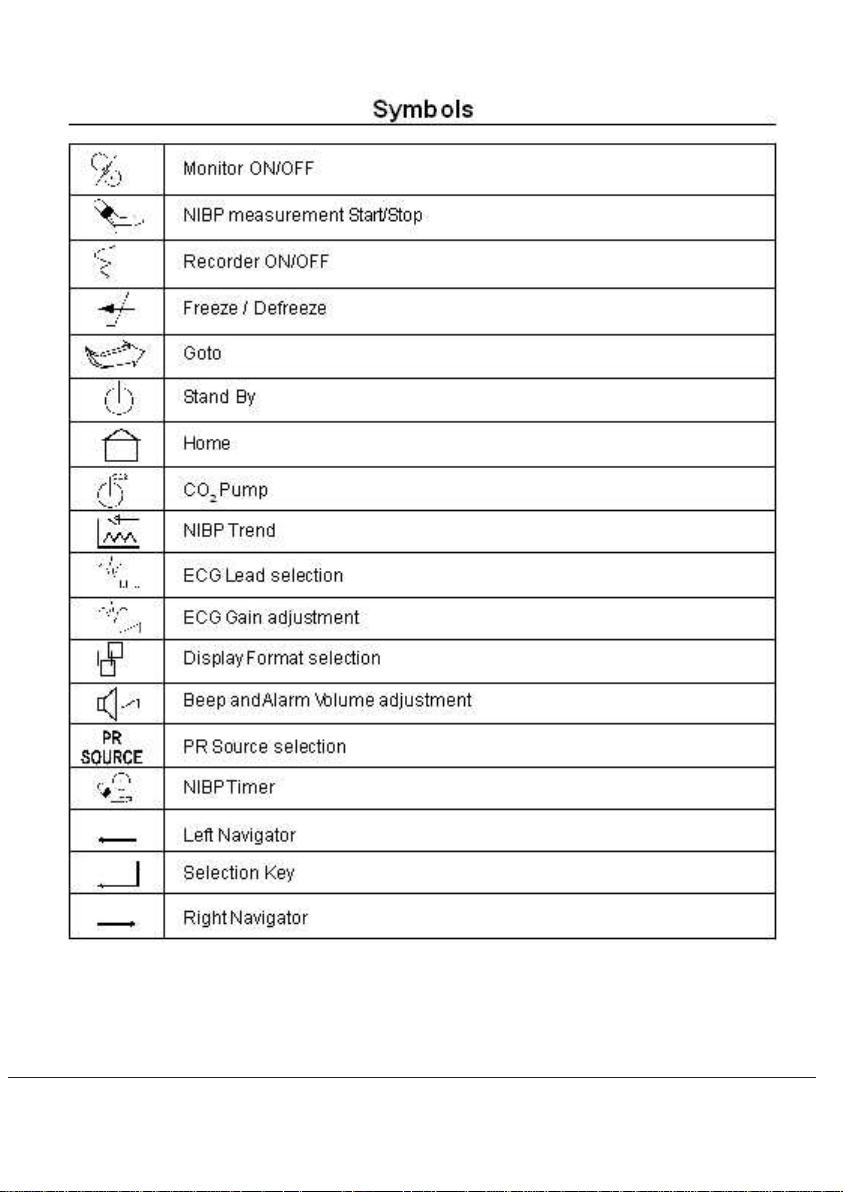
Symbols
~
!
*
Mains 110 / 230 Volts ON indicator
Unit ON indicator
Equipotential ground
Attention, refer to manual
Defibrillation – Proof type-CF of Applied Part
Defibrillation – Proof type-BF of Applied Part
Global Alarm suspended
Alarm Acknowledge
Indicates valid QRS/Pulse detection
Indicates detection of PR from Plethysmograph
Indicates detection of PR from NIBP
$ Indicates detection of PR from IBP
Manufacturer
Authorised representative in the european community
Planet 55
vii
viii

Abbreviations
SpO
2
Oxygen Saturation in %
HR Heart Rate (derived from ECG)
BPM Beats Per Minute (HR/PR)
BPM Breaths Per Minute (RR)
FLT Fault
SYS Systolic Blood Pressure
DIA Diastolic Blood Pressure
MEAN Mean Blood Pressure
PR Pulse Rate
RR Respiration Rate
EtCO
FiCO
2
2
End Tidal Carbon dioxide
Fractional Inspired Carbon dioxide
DPI Dot Per Inch
CNS Central Nursing Station
PA Physiological Alarm
TA Technical Alarm
CIC Communication Interface Card
NA No Alarm
Planet 55
ix
1
Planet 55
DISPLAY, CONTROLS,
CONNECTIONS
AND OUTPUTS
1.1

Notes:
1.2
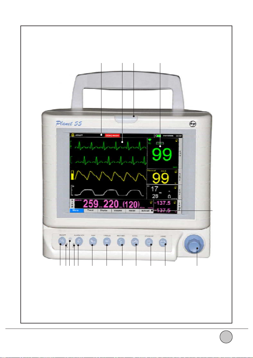
Front Panel
17 16 15 14
13
Planet 55
1 2 3 4 5 6 7 8 9 10 11 12
Figure 1.1
1.3

Front Panel Description
1 Monitor ON/OFF switch To switch ON or switch OFF the monitor (Unit should
be connected to the mains supply or to the internal
battery).
2 Mains Indicator Amber color LED turns ON when Mains is connected.
3 Remote sensor To sense the remote signals.
4 Monitor ON indicators Amber LED ON indicates Mains ON.
Green LED ON indicates Monitor ON.
Amber LED OFF and Green LED ON indicates unit
is ON in battery operation mode.
5 Alarm Acknowledge On pressing this key, all audio alarms are muted or
suspended. When Audio/Visual alarms are indicated
by the unit, this key acts as alarm acknowledge key.
6 NIBP Start/Stop This key is used to start/stop the Auto/Manual NIBP
measurement.
7 Freeze/Defreeze To Freeze / Defreeze the screen, this key is used.
8 Record To Start / Stop recorder.
9 Goto This key used as a short cut key for Menu option.
10 Stand By This key is used for the monitor to go to stand by
mode. Press again this key to monitor real time
screen. Stand By mode is a power saving option.
11 Home To come back directly to the Main screen, from any
other screen.
1 2 Optical Encoder This is a special rotating knob used for multipurpose
applications. Rotating the Optical Encoder in clockwise
or anti-clockwise direction, moves the cursor
(highlighted rectangular block) right or left in the Menu
area of the screen. Pressing the Optical Encoder
selects the particular function.
13 Menu Display Area Displays Main menus.
14 Parameter/Numeric Displays numerical values for all parameters which
are present.
1.4

15 Alarm Indicator Gives flashing Yellow color indication for cable /
accessory related alarms like cable coming off patient
and flashing Red color indication for patient related
alarms, e.g. when the value of any parameter being
monitored goes above or below the set alarm limits.
Audio frequency [AAMI 4.1.2.1(i)] :
Red alarm: 1.7 kHz
Yellow alarm : 1.4 kHz
Video frequency :
Red alarm : 2 Hz (250ms ON, 250ms OFF)
Yellow alarm : 0.5 Hz (1s ON, 1s OFF)
Fixed 3 minutes realarm facility is present.
Crossed bell indication for alarm silence.
16 Waveform Display Area Displays waveforms. Maximum 4 channel
monitor.
17 Message Display Area Displays error messages.
Planet 55
1.5

Rear Panel
0843
1.6
1
3
2
Figure 1.2
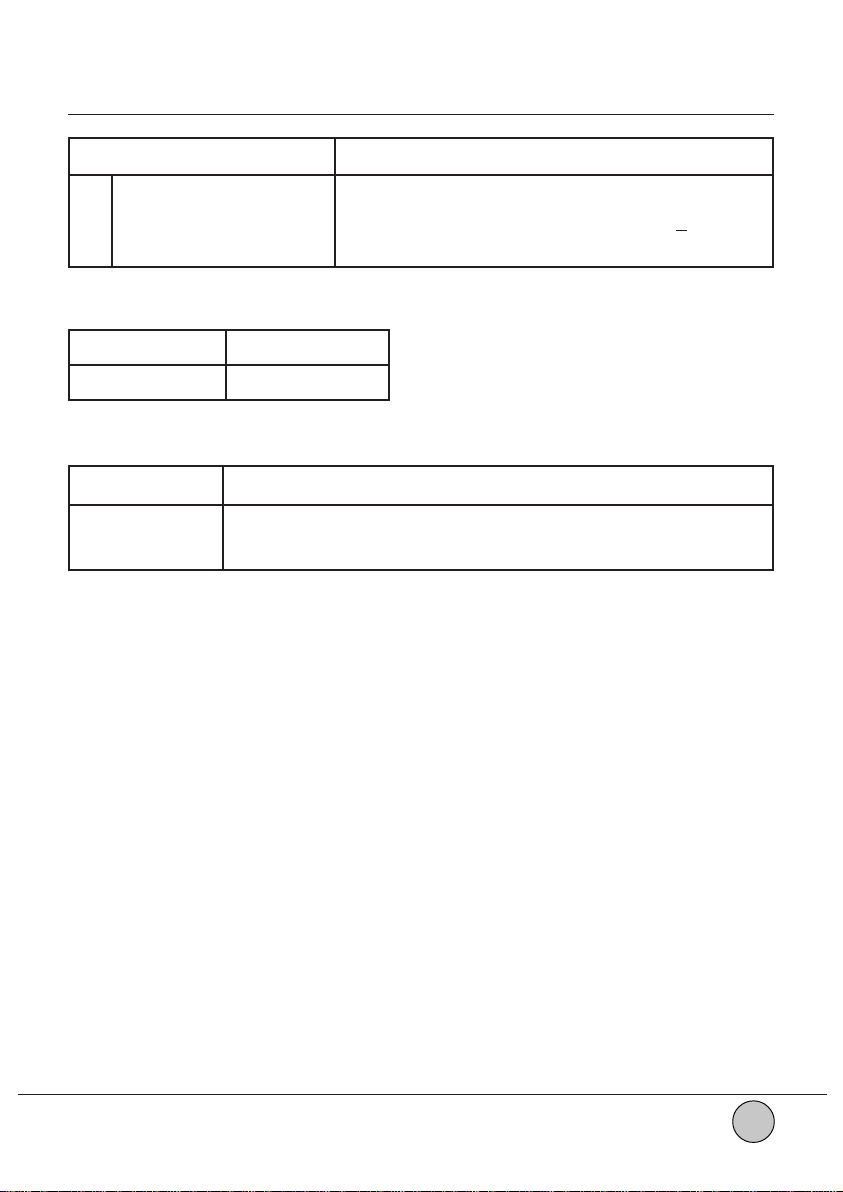
Rear Panel Description
Connector Function
1 Equipotential Ground For external grounding.
2 Mains Plug Connection for 95-265V AC, 50Hz/60Hz + 5%.
3 CIC Communication Interface Card.
CIC available in Planet 55:
CIC Connectors
CIC-4 PC Dump + CNS
Usage of the connectors as shown below:
Connector Description
DB9 PC Dump.
USB Central Nursing Station.
Planet 55
1.7
Left Side Panel
1
2
3
4
5
6
7
8
Figure 1.3
1.8
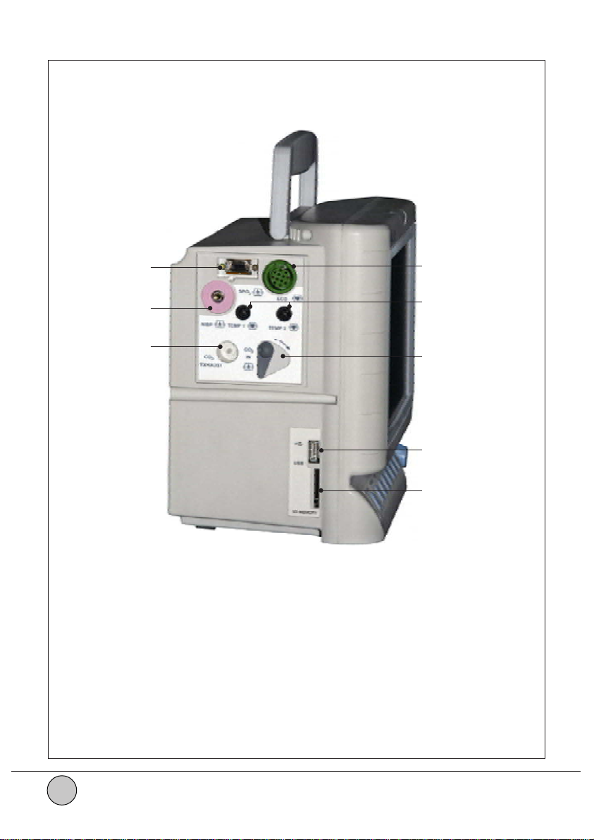
Left Side Panel Description
Connector Function
1SpO
2
To interface SpO2 sensor to the monitor with the help of
extension cable.
2 NIBP To interface NIBP cuff to the monitor with the help of
hose tube.
3CO2 Exhaust To vent for CO2 gas sample.
4 ECG To interface ECG 3lead or 5lead cable with monitor.
5 TEMP T o interface Temperature probe to the monitor.
6CO
2
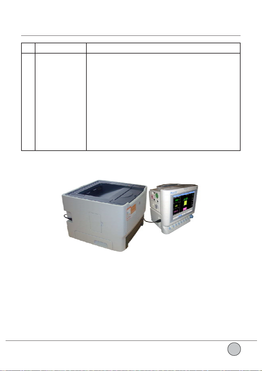
7 USB To connect external Printer
To Input for gas sample.
#
(Refer Figure 1.4) / for
software upgradation*/ for Trend download*.
8 SD Memory** To transfer the trend data from one monitor to another.
Figure 1.4
* Use 1GB or 512 MB of Sandisk make.
** Use 1GB, 2GB or 512 MB of Sandisk make.
# Use USB Printer which supports PCL5e and PCL6.
Planet 55
1.9
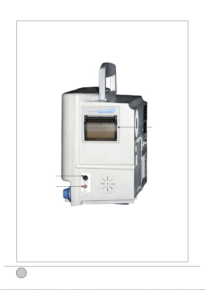
Right Side Panel
1
1.10
2
3
Figure 1.5

Right Side Panel Description
Connector Function
1 Recorder To print the waveform with the digital values.
2 Nurse Call Configurable relay to activate nurse call.
3 Defib. Sync For synchronizing monitor with defibrillator.
Planet 55
1.11
Procedure To Connect And Disconnect The Connectors
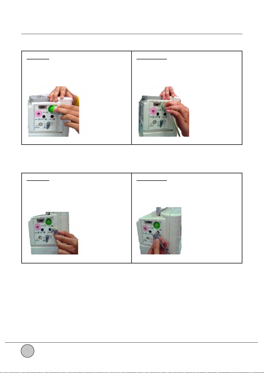
ECG :
Connect Disconnect
Align the notch of the ECG cable connector Gently pullout the ECG cable connector
with the connector slot on the Side panel a s shown below.
with the unit and insert the cable as shown
below.
Figure 1.6 Figure 1.7
Temp :
Connect Disconnect
Insert the Temperature connector in the Gently pullout the Temperature connector
slot (Temp 1 / Temp 2) provided on the as shown below.
Side panel of the unit as shown below.
Figure 1.8 Figure 1.9
1.12
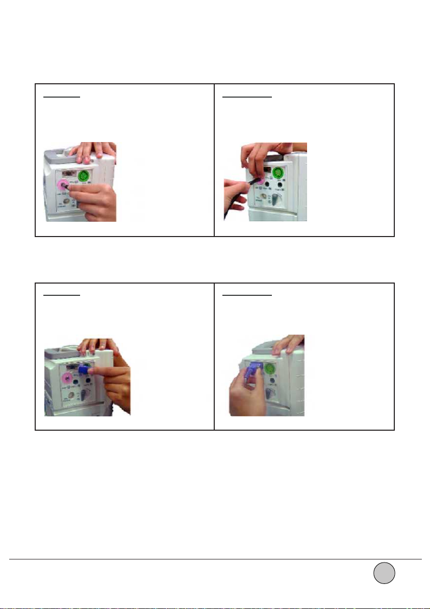
NIBP :
Connect Disconnect
Insert the NIBP connector in the slot Press the NIBP connector on the side
provided on the side panel of the unit as panel of the unit and remove the connector
shown below. as shown below.
Figure 1.10 Figure 1.11
SpO
:
2
Connect Disconnect
Align the SpO2 connector with the D-type Press the release notch of the connector
connector slot on the side panel of the unit and remove the connector as shown
and insert as shown below. below.
Figure 1.12 Figure 1.13
Planet 55
1.13
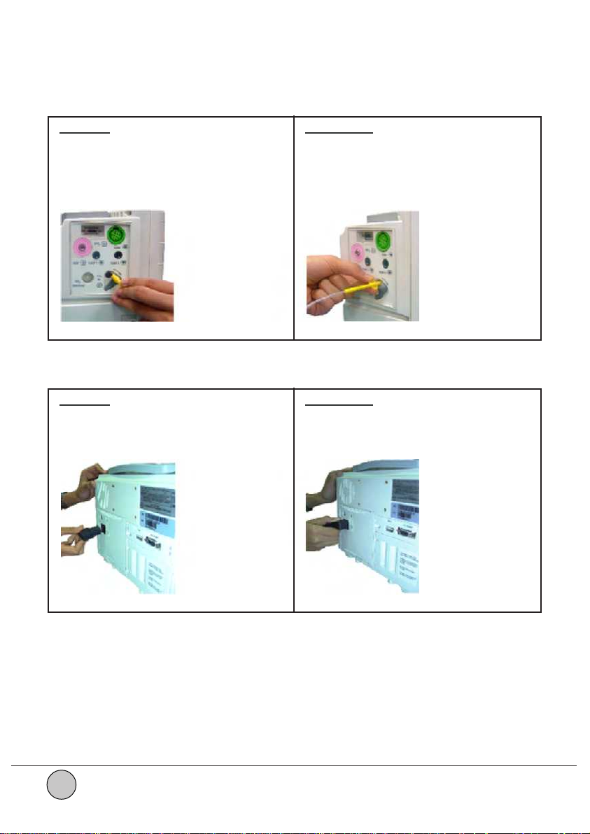
CO2 :
Connect Disconnect
a) Open the CO2 inlet shutter in the a) Turn the CO2 connector in anticlockwise
direction as shown below. direction to unlock as shown below.
b) Insert the CO2 connector and turn b) Gently pullout the CO2 connector
clockwise direction to lock as shown as close the inlet shutter.
below.
Figure 1.14 Figure 1.15
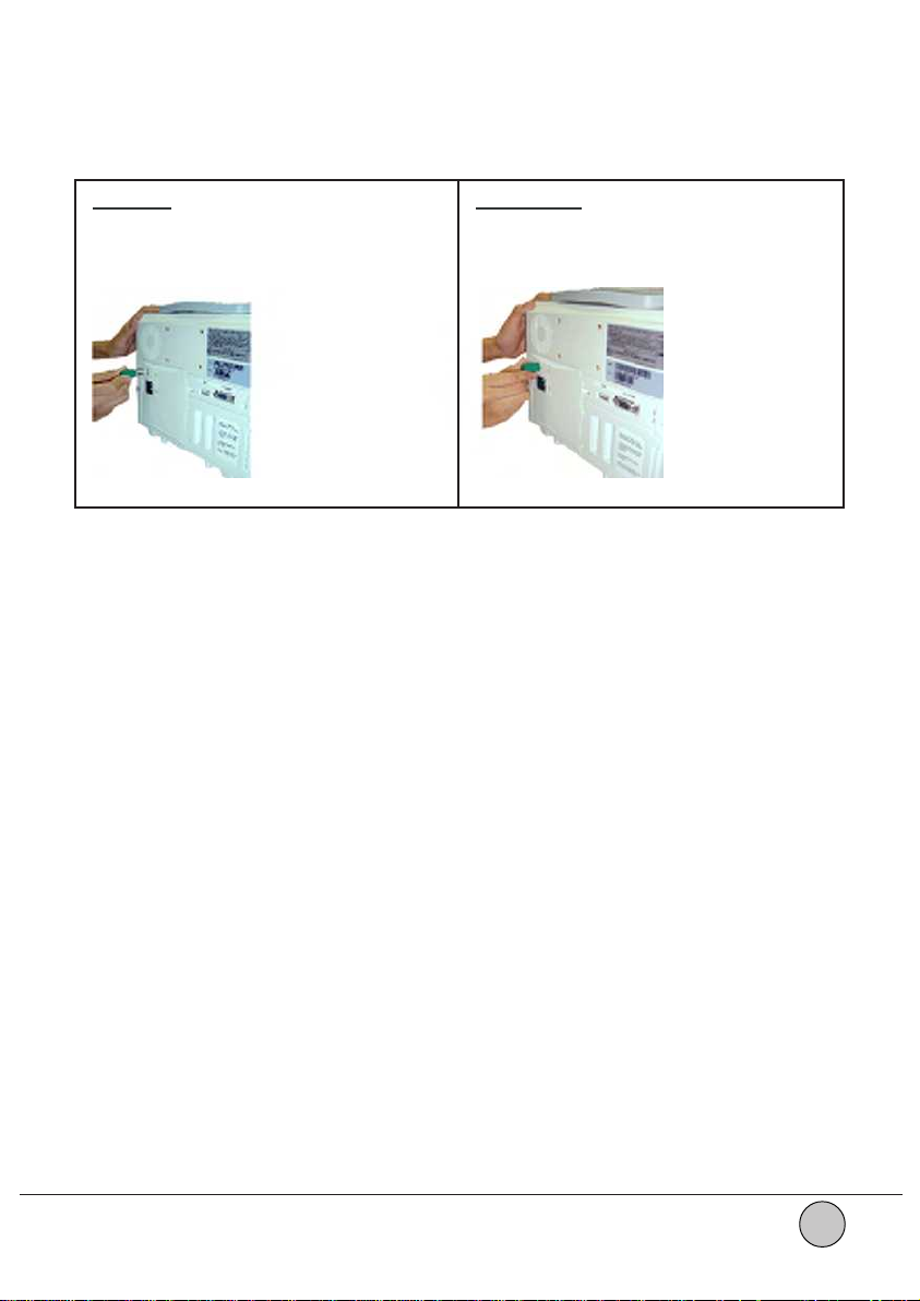
Power cord :
Connect Disconnect
Insert the Power cord connector in the Gently pullout the Power cord connector
solt provided on the Rear panel of the as shown below.
unit as shown below.
Figure 1.16 Figure 1.17
1.14
Grounding cable :
Connect Disconnect
Insert the Grounding cable connector in Gently pullout the Grounding cable
the slot provided on the Rear panel of connector a s shown below.
the unit as shown below.
Figure 1.18 Figure 1.19
Planet 55
1.15
 Loading...