

www.larius.eu
Zeus Liner
with piston pump
Street marking
OPERATING AND MAINTENANCE INSTRUCTION
YOUR PARTNER FOR ALL YOUR MARKING NEEDS SINCE 1969
Ediz. 001 - 12/2015

Due to a constant product improvement programme, the factory reserves the
right to modify technical details mentioned in this manual without prior notice.

ZEUS LINER
AA
BB
CCDDEE
FF
GGHHII
JJ
KK
LL
MM
NN
OO
PP
QQ
RR
SS
TT
UU
VV
WW
XX
ZZ
YY
STREET MARKING WITH PISTON PUMP
INTRODUCTION .................................................. p.1
WARNINGS .......................................................... p.2
WORKING PRINCIPLE ........................................ p.3
TECHNICAL DATA ............................................... p.5
DESCRIPTION OF THE EQUIPMENT ................. p.7
TRANSPORT AND UNPACKING ......................... p.9
SAFETY RULES ................................................... p.9
Conditions of guarantee ...................................... p.10
SETTING-UP ........................................................ p.10
Flexible re-circulation tube connection ........... p.10
Pump unit flexible tube connection
Flexible tube and spray gun connection ......... p.11
Starting the motor ............................................. p.11
Washing of the new equipment ....................... p.12
Preparing the produc ........................................ p.14
REGULATIONS ....................................................... p.15
Adjusting the guns support arm ......................... p.15
WORKING ............................................................ p.15
Set up procedure ............................................ p.15
Adjustment pump unit speed ......................... p.16
Spray adjustment ............................................ p.16
CLEANING AT THE END OF THE WORK ............ p.17
GENERAL MAINTENANCE
Daily ......................................................................... p.18
Periodically ..............................................................p.18
......................................p.18
.................. p.10
ROUTINE MAINTENANCE .......................................p.18
Check on the packing nut
PROBLEMS AND SOLUTIONS ........................... p.19
M
CORRECT PROCEDURE OF
DECOMPRESSION .............................................. p.21
N
REPLACEMENT OF THE PUMPING
GROUP’S GASKETSE ......................................... p.22
Pit stop maintenance ....................................... p.22
SPARE PARTS
COMPLETE STEERING UNIT ............................. p.31
COMPLETE FRAME
COMPLETE
COMPLETE 50L TANK ........................................ p.36
COMPLETE 20L TANK ......................................... p.37
COMPLETE BOX ................................................. p.38
COMPLETE BOX TRASFORMER
RE-CIRCULATION UNIT COMPLETE
GUNS ARM UNIT
COMPLETE MECHANICAL UNIT ........................ p.42
COMPLETE PUMPING UNIT ............................... p.44
ACCESSORIES .................................................... p.46
.............................................. p.32
ZEUS LINER ..................................... p.34
................................................... p.41
............................... p.18
...............................
....................... p.40
p.39
Ed. 001 - 12/2015
WE ADVISE THE USE OF THIS EQUIPMENT ONLY BY PROFESSIONAL OPERATORS.
ONLY USE THIS MACHINE FOR USAGE SPECIFICALLY MENTIONED IN THIS MANUAL.
Thank you for choosing a LARIUS S.R.L. product.
As well as the product purchased,
you will receive a range of support services
enabling you to achieve the results desired,
quickly and professionally.
www.larius.eu
1
ZEUS LINER
WARNINGS
Read this operator’s manual carefully before using the equipment.
An improper use of this machine can cause injuries to people or things.
Do not use this machine when under the influence of drugs or alcohol.
Do not modify the equipment under any circumstances.
Use products and solvents that are compatible with the various parts of the equipment, and read the manufacturer’s warnings
carefully.
See the Technical Details for the equipment given in the Manual.
Check the equipment for worn parts once a day. If any worn parts are found, replace them using ONLY original spare parts.
Keep children and animals away from work area.
Comply with all safety standards.
It indicates an accident risk or serious damage to equipment if this warning is not followed.
It indicates a fire or explosion risk if this warning is not followed.
Eliminate all ignition sources such as pilot lights, cigarettes, portable electric lamps and plastic drop cloths.
Keep work area free of debris.
ONLY use this equipment in a well ventilated area.
EARTH ALL THE EQUIPMENT LOCATED IN THE WORK AREA.
Do not form connections or switch light switches on or off if the air contains inflammable fumes.
If electrical shocks or discharges are encountered the operation being carried out using the equipment must be stopped immediately.
Keep a fire extinguisher at hand in the immediate vicinity of the work area.
The table below provides the meaning of the symbols used in this manual in relation to using, earthing,
operating, maintaining, and repairing of this equipment.
It indicates wound and finger squashing risk due to movable parts in the equipment.
Tenersi lontano dalle parti in movimento.
Do not use the equipment without the proper protection.
Before any inspection or maintenance of the equipment, carry out the decompression procedure explained in this manual, and
prevent any risk of the equipment starting unexpectedly.
Report any risk of chemical reaction or explosion if this warning has not been given.
There is a risk of injury or serious lesion related to contact with the jet from the spray gun. If this should occur, IMMEDIATELY
contact a doctor, indicating the type of product injected.
Do not spray before the guard has been placed over the nozzle and the trigger on the spray gun.
Do not put your fingers in the spray gun nozzle.
Once work has been completed, before carrying out any maintenance, complete the decompression procedure explained in
this manual.
It indicates important recommendations about disposal and recycling process of products in accordance with the environmental
regulations.
Report any danger of electric shock if the warning and presence of live electrical parts has not been indicated.
Store in a dry place and do not expose to the rain.
Check that the cables are in good condition.
Switch off the equipment and discharge any electricity before cleaning or maintaining the equipment.
Mark any clamps attached to earth cables.
Use ONLY 3-wire extension cords and grounded electrical outlets.
Before starting work make sure that the electrical system is earthed and that it complies with safety standards.
www.larius.eu
2
It is obligatory to wear suitable clothing as gloves, goggles and face shield.
Wear clothing that complies with the safety standards in force in the country in which the equipment is used.
Do not wear bracelets, earrings, rings, chains, or anything else that may hinder the operator’s work.
Do not wear clothing with wide sleeves, scarves, ties, or any other piece of clothing that could get tangled up in moving parts of
the equipment during the work, inspection, or maintenance cycles.
Ed. 001 - 12/2015
AA
ZEUS LINER
WORKING PRINCIPLE
The LARIUS EXCALIBUR unit is defined “piston pump”.
An piston pump is used for high pressure painting without air
(from this process derives the term ”airless”).
The internal combustion engine, mounted upon the undercarriage, powers the alternative piston pump.
A cam shaft and a connecting rod allow to obtain the reciprocating motion necessary to the working of the “pumping
group” piston.
The piston movement produces a “vacuum”.
The product is sucked, pushed towards the pump outlet and
then sent to the gun through the flexible hose.
A electronic device, allows to adjust and control the pressure
of the material coming out of the pump.
A safety valve avoiding overpressure, guarantees the total
reliability of the equipment.
The control zone allows for the possibility of:
• Activating the dispensing spray gun;
• Enabling or disabling the frontal steering wheel;
• Adjust the pressure of work;
The paint dries quickly and the line is defined in a uniform
manner with a single coat. The airless function requires the
use of filtered paint which is specifically designed for airless
application. This means that the paint is homogeneous, of a
smooth and uniform consistency and will not form crusts, nor
will it become gelatinous or thick. With this airless line-marker,
the paint adheres firmly to all types of pavement, with optimal
visibility, and is resistance to wear caused both by traffic as
well as atmospheric agents.
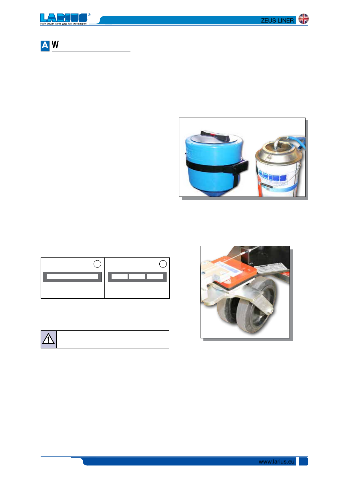
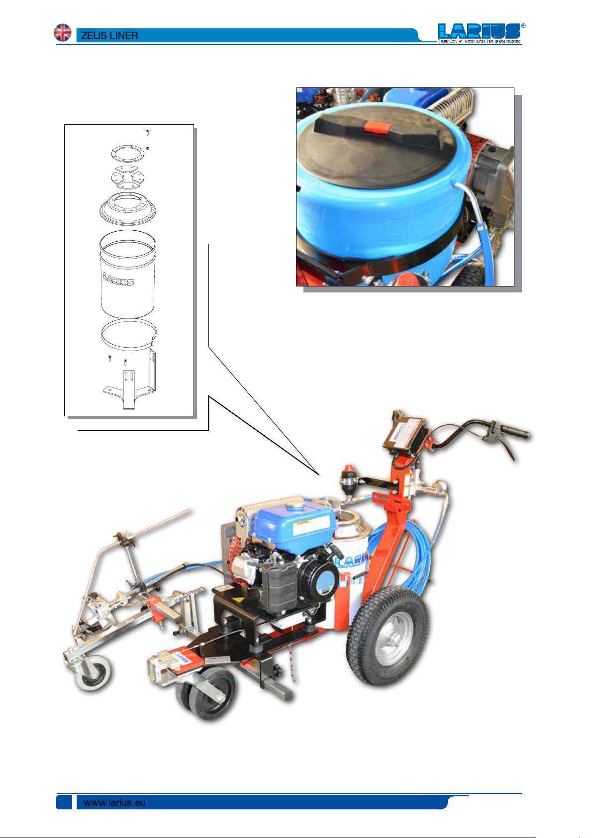
LT. 20 TANKLT. 50 TANK
This type of equipment is capable of painting one line at a time
in a single color.
The line can be either solid or dotted, based on the working
requirements.
1 2
SOLID LINE BROKEN LINE
ZEUS LINER is ideal for medium marking and maintenance
jobs.
Use water or non-refractive solvent filtered paint
specifically designed for airless application.
ZEUS LINER allows for the marking and maintaining of all types
lines on highways, freeways, pedestrian crossings, parking lots
and squares, as well as every horizontal marking required by
the highway code.
Airless marking has numerous proven benefits with respect to
line-markers with pressurised tanks, which have been rendered
obsolete by airless-technology line markers.
Airless line-marking guarantees:
• Decreased Environmental Impact;
• Decreased drying time.
In the LARIUS models, the paint canister can be loaded directly
upon the undercarriage or else poured into the non-stick (20
l or 50 l, depending on the model). In every case, cleaning,
maintenance and colour change operations are facilitated.
The line-marker is equipped with pivoting frontal wheel which
even increases the agility of the larger models.
High yield, high efficiency, high versatility.
This line-marker utilises non-premixed paints. This allows it
to achieve about 30 % more yield with respect to standard
line-markers. Every model is also an airless spray gun which
can be used in the construction/decoration sector together
with washable products, enamels, breathable paints and
flooring resins.
A vast assortment of accessories is available to satisfy every
customer demand.
Ed. 001 - 12/2015
www.larius.eu
3
ZEUS LINER
Lt. 50 Tank
Lt. 20 Tank
www.larius.eu
4
Ed. 001 - 12/2015
BB
TECHNICAL DATA
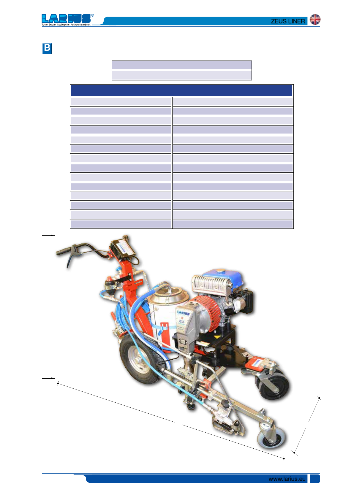
ZEUS LINER
ZEUS LINER 50L RIF. 4560
ZEUS LINER 25L RIF. 4561
Internal combustion engine power
Max. Delivery
Max. pressure
Airless spray-gun
Sizes of the furnished nozzles
Tank
Colours
Manual line-marking
Applications
Multi-use sprayer
Weight
Lenght
Height
Width
ZEUS LINER
4 kW ÷ 5 kW (upon availability)
3,5 l/min
210 bar
AT 250
11x40 - 13x40 - 15x40
50l - 20l
1
series
Medium road-marking and maintenance
series
105 kg
(A) 1650 mm
(B) 1000 mm
(C) 750 mm
B
Ed. 001 - 12/2015
A
www.larius.eu
C
5
ZEUS LINER
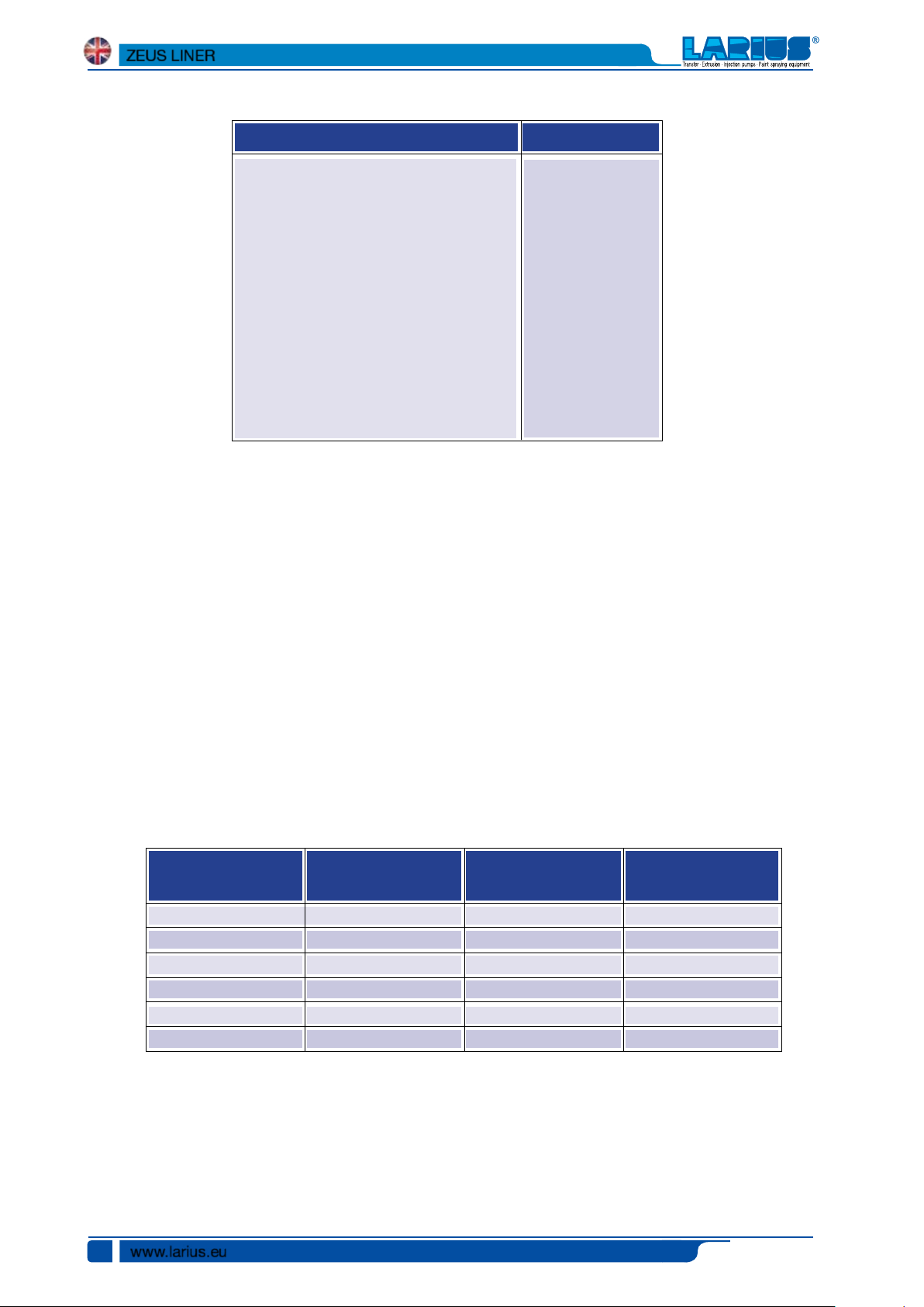
Standard equipment Accessories
N°1 Filter with pressure gauge
N°1 High pressure tube 1/4”, 10 m Ref. 35017
N°1 Recirculation tube
N°1 50 L gravity tank + closure valve and
extractible filter
N°1 Manual airless spray-gun AT250
N°1 Super fast clean base
N°1 Super fast clean nozzle 11-40
N°1 Super fast clean nozzle 13-40
N°1 Super fast clean nozzle 15-40
N°1 Tool pack
N° 1 Gun guide arm
SECTORS OF USE
• External or underground parking lots (schools, hotels, airports,
supermarkets, train stations, subway stations, ports);
• External public areas;
• Industrial and exhibition building zones;
Ref. 4502
Bead distributor for
automatic sprayguns
Ref.4038
Laser pointer kit
Ref. 4506
Working spotlight
• Freeway service areas and service stations;
• Pedestrian median lines, intersections, bicycle tracks, reserved
lanes;
• Internal and external logistic area markings;
• Playing fields.
NOZZLES POSITION TABLE
Nozzle height
from ground
10 cm
15 cm
20 cm
25 cm
30 cm
35 cm
20-degree angle
Line Width
~ 3 cm
~ 6 cm
~ 10 cm
40-degree angle
Line Width
~ 5 cm
~ 7 cm
~ 8 cm
~ 10 cm
~ 12 cm
60-degree angle
Line Width
~ 10 cm
~ 13 cm
~ 16 cm
~ 20 cm
~ 23 cm
~ 26 cm
www.larius.eu
6
Ed. 001 - 12/2015
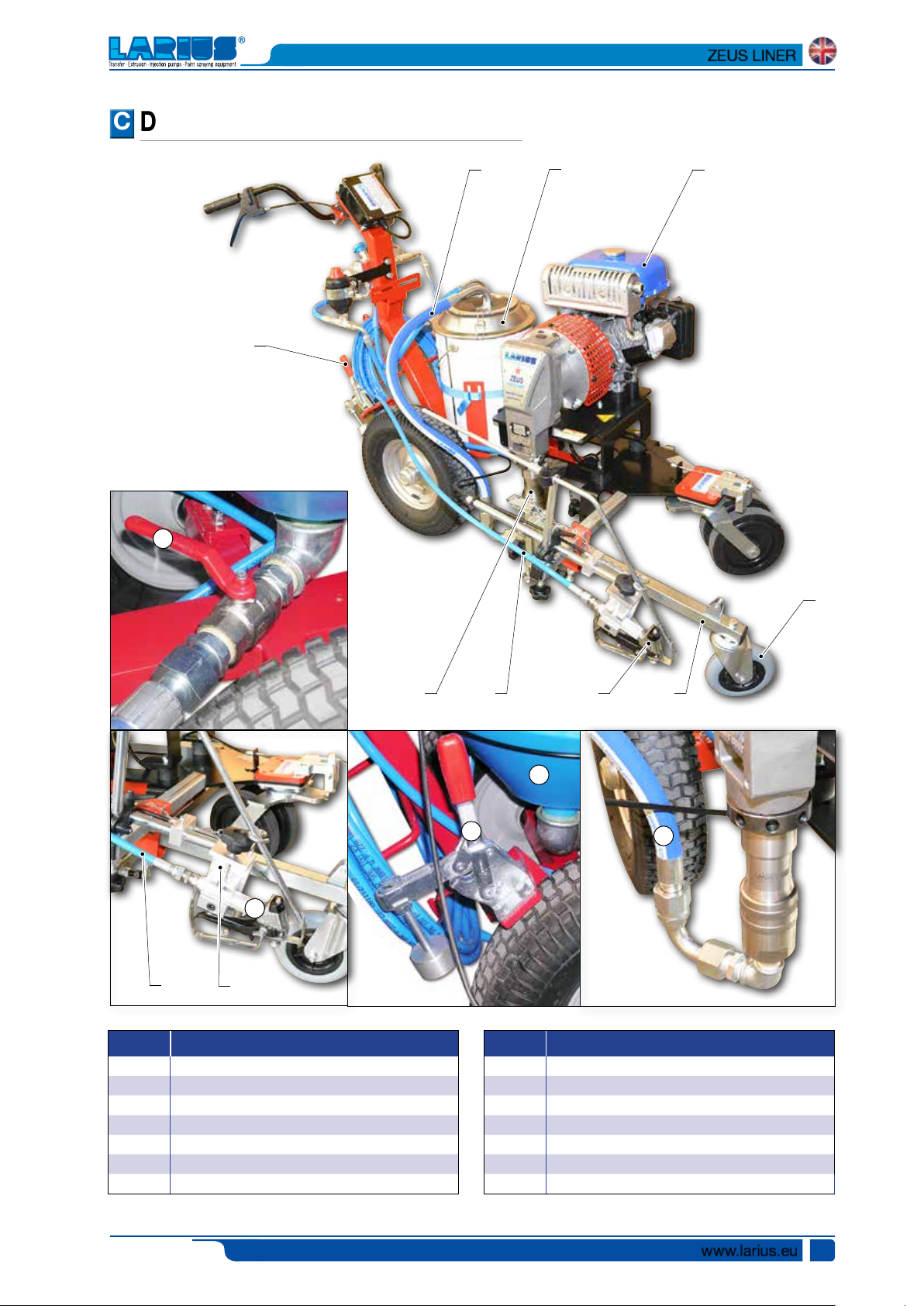
DESCRIPTION OF THE EQUIPMENT
CC
ZEUS LINER
2
9
3
1
8
7
6
4
POS. Description
1-1A
lt. 20 tank - lt. 50 tank
2
Recirculation tube
3
Suction intake valve (versione 50 lt.)
4
Product supply tube
5
Pumping group
6
Gun AT250
11
5 4 6
1A
9
POS. Description
7
Pivoting wheel
8
Gasoline tank
9
Brake
10
Draught hose (20 l version)
11
Gun-holder arm
11
10
Ed. 001 - 12/2015
www.larius.eu
7
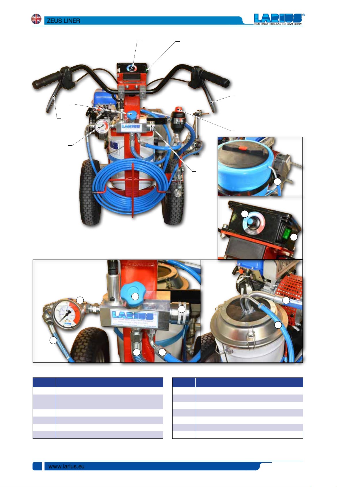
ZEUS LINER
12
15
17
13
14
18
24
16
21
22
12
15
19 23
13
14
20
16
19
POS. Description
12
Manometer
13
Potentiometer for adjusting
the operating pressure
14
ON/OFF switch
15
Safety-recirculation valve
16
Plug for filter
17
Directional wheel lock/release lever
www.larius.eu
8
POS. Description
18
Gun operating lever
19
Recirculation lines
20
Draught lines
21
Recirculation lines (50 l version)
22
Gun connection lines
23
Pumping unit connection lines
24
Compensation valve
Ed. 001 - 12/2015
DD
EE
ZEUS LINER
TRANSPORT
AND UNPACKING
•
The packed parts should be handled as indicated in the
symbols and markings on the outside of the packing.
•
Before installing the equipment, ensure that the area to be
used is large enough for such purposes, is properly lit and
has a clean, smooth floor surface.
The user is responsible for the operations of unloading and handling and should use the maximum
care so as not to damage the individual parts or
injure anyone.
To perform the unloading operation, use only qualified
and trained personnel (truck and crane operators, etc.)
and also suitable hoisting equipment for the weight
of the installation or its parts.
Follow carefully all the safety rules.
The personnel must be equipped with the necessary
safety clothing.
•
The manufacturer will not be responsible for the unloading
operations and transport to the workplace of the machine.
•
Check the packing is undamaged on receipt of the equipment. Unpack the machine and verify if there has been
any damage due to transportation.
In case of damage, call immediately LARIUS and the
Shipping Agent. All the notices about possible damage or
anomalies must arrive timely within 8 days at least from
the date of receipt of the plant through Registered Letter
to the Shipping Agent and to LARIUS.
The disposal of packaging materials is a customer’s
competence and must be performed in accordance
with the regulations in force in the country where the
plant is installed and used.
It is nevertheless sound practice to recycle packaging materials in an environment-friendly manner as
much as possible
.
SAFETY RULES
• THE EMPLOYER SHALL TRAIN ITS EMPLOYEES ABOUT
ALL THOSE RISKS STEMMING FROM ACCIDENTS, ABOUT
THE USE OF SAFETY DEVICES FOR THEIR OWN SAFETY
AND ABOUT THE GENERAL RULES FOR ACCIDENT
PREVENTION IN COMPLIANCE WITH INTERNATIONAL
REGULATIONS AND WITH THE LAWS OF THE COUNTRY
WHERE THE PLANT IS USED.
• THE BEHAVIOUR OF THE EMPLOYEES SHALL STRICTLY
COMPLY WITH THE ACCIDENT PREVENTION AND ALSO
ENVIRONMENTAL REGULATIONS IN FORCE IN THE
COUNTRY WHERE THE PLANT IS INSTALLED AND USED.
• KEEP YOUR WORK PLACE CLEAN AND TIDY. DISORDER
WHERE YOU ARE WORKING CREATES A POTENTIAL RISK
OF ACCIDENTS.
• ALWAYS KEEP PROPER BALANCE AVOIDING UNUSUAL
STANCE.
• BEFORE USING THE TOOL, ENSURE THERE ARE NOT
DAMAGED PARTS AND THE MACHINE CAN WORK PROPERLY.
• ALWAYS FOLLOW THE INSTRUCTIONS ABOUT SAFETY
AND THE REGULATIONS IN FORCE.
• KEEP THOSE WHO ARE NOT RESPONSIBLE FOR THE
EQUIPMENT OUT OF THE WORK AREA.
• NEVER EXCEED THE MAXIMUM WORKING PRESSURE
INDICATED.
• NEVER POINT THE SPRAY GUN AT YOURSELVES OR
AT OTHER PEOPLE. THE CONTACT WITH THE CASTING
CAN CAUSE SERIOUS INJURIES. IN CASE OF INJURIES
CAUSED BY THE GUN CASTING, SEEK IMMEDIATE MEDICAL ADVICE SPECIFYING THE TYPE OF THE PRODUCT
INJECTED. NEVER UNDERVALUE A WOUND CAUSED BY
THE INJECTION OF A FLUID.
• ALWAYS DISCONNECT THE SUPPLY AND RELEASE THE
PRESSURE IN THE CIRCUIT BEFORE PERFORMING
ANY CHECK OR PART REPLACEMENT OF THE EQUIPMENT.
• NEVER MODIFY ANY PART IN THE EQUIPMENT. CHECK
REGULARLY THE COMPONENTS OF THE SYSTEM. REPLACE THE PARTS DAMAGED OR WORN.
• TIGHTEN AND CHECK ALL THE FITTINGS FOR CONNECTION BETWEEN PUMP, FLEXIBLE HOSE AND SPRAY
GUN BEFORE USING THE EQUIPMENT.
• ALWAYS USE THE FLEXIBLE HOSE SUPPLIED WITH STANDARD KIT. THE USE OF ANY ACCESSORIES OR TOOLING
OTHER THAN THOSE RECOMMENDED IN THIS MANUAL,
MAY CAUSE DAMAGE OR INJURE THE OPERATOR.
• THE FLUID CONTAINED IN THE FLEXIBLE HOSE CAN
BE VERY DANGEROUS. HANDLE THE FLEXIBLE HOSE
CAREFULLY. DO NOT PULL THE FLEXIBLE HOSE TO
MOVE THE EQUIPMENT. NEVER USE A DAMAGED OR A
REPAIRED FLEXIBLE HOSE.
Read carefully and entirely the following instructions before using the product. Please save
these instructions in a safe place.
The unauthorised tampering/replacement of one
or more parts composing the machine, the use of
accessories, tools, expendable materials other than
those recommended by the manufacturer can be
a danger of accident.
The manufacturer will be relieved from tort and
criminal liability.
Ed. 001 - 12/2015
www.larius.eu
9
FF
ZEUS LINER
The high speed of travel of the product in the hose
can create static electricity through discharges
and sparks.
It is suggested to earth the equipment.
The gun is earthed through the high pressure
flexible hose.
All the conductors near the work area must be
earthed.
• NEVER SPRAY OVER FLAMMABLE PRODUCTS OR SOLVENTS IN CLOSED PLACES.
• NEVER USE THE TOOLING IN PRESENCE OF POTENTIALLY
EXPLOSIVE GAS.
Always check the product is compatible with the
materials composing the equipment (pump, spray
gun, flexible hose and accessories) with which it
can come into contact. Never use paints or solvents containing halogen hydrocarbons (as the
methylene chloride).
If these products come into contact with aluminium
parts can provoke dangerous chemical reactions
with risk of corrosion and explosion.
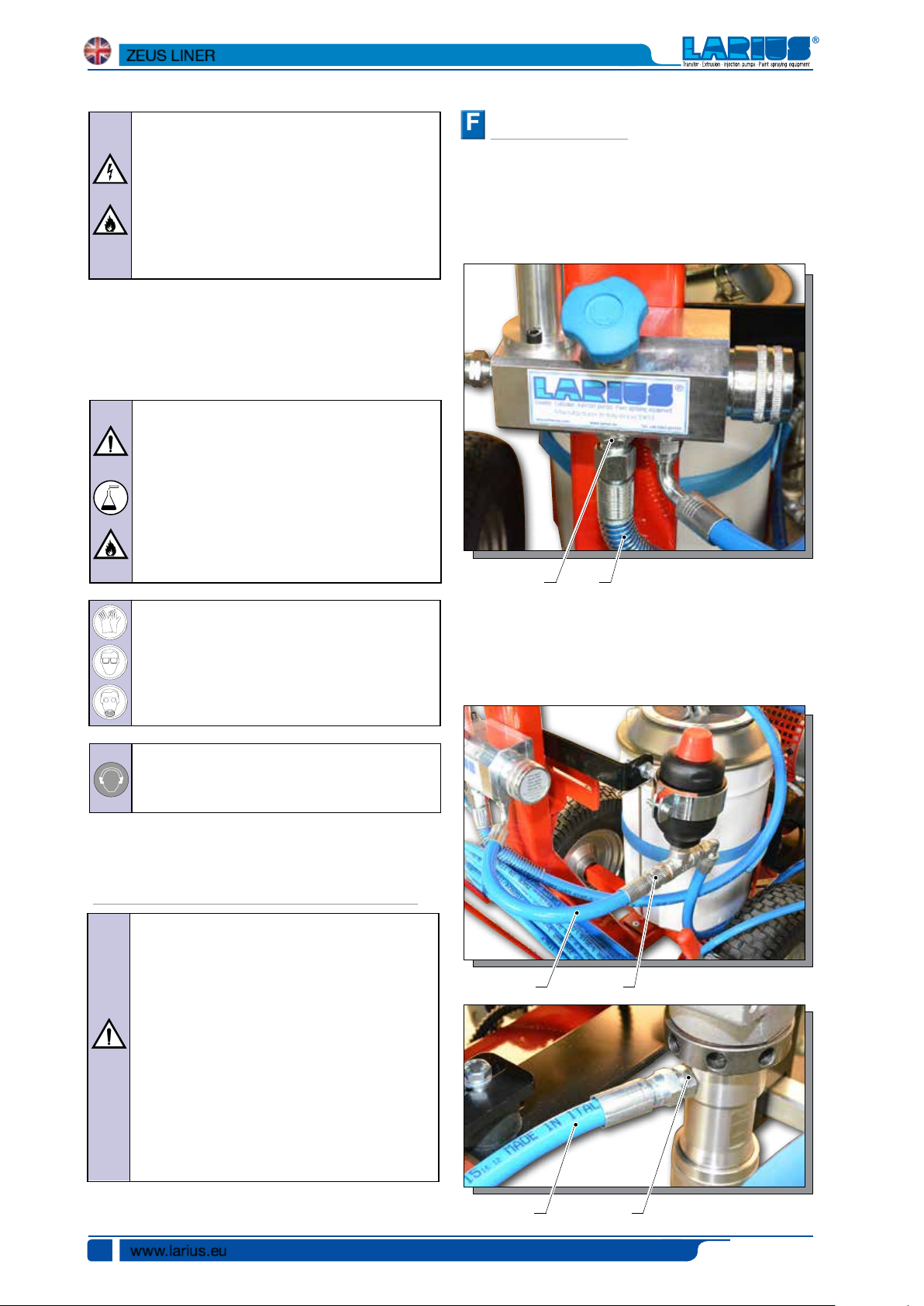
SETTING-UP
TUBE CONNECTIONS
Flexible re-circulation tube connection
• Connect the flexible re-circulation tube
(F2)
ensuring to tighten the fittings (the use of two wrenches
is suggested)
F2
.
F1
(F1)
to the connector
IF THE PRODUCT TO BE USED IS TOXIC, AVOID
INHALATION AND CONTACT BY USING PROTECTION GLOVES, GOGGLES AND PROPER
FACE SHIELDS.
TAKE PROPER SAFETY MEASURES FOR THE
PROTECTION OF HEARING IN CASE OF WORK
NEAR THE PLANT.
Pump unit flexible tube connection
• Connect the pump unit’s flexible tube
(F4) of the compensation valve and then to the connector
(F5) of the pumping unit, taking care to tighten the fittings
well (we recommend using two wrenches).
CONDITIONS OF GUARANTEE
The conditions of guarantee do not apply in the
following situations:
- improper washing and cleaning of components
causing malfunction, wear or damage to the
equipment or any of its parts;
- improper use of the equipment;
- use that does not conform with applicable national legislation;
- incorrect or faulty installation;
- modifications, interventions and maintenance that
have not been authorised by the manufacturer;
- use of non-original spare parts or parts that do
not correspond to the specific model;
- total or partial non-compliance with the instructions provided.
F3
F4
(F3)
to the connector
www.larius.eu
10
F3
F5
Ed. 001 - 12/2015
ZEUS LINER
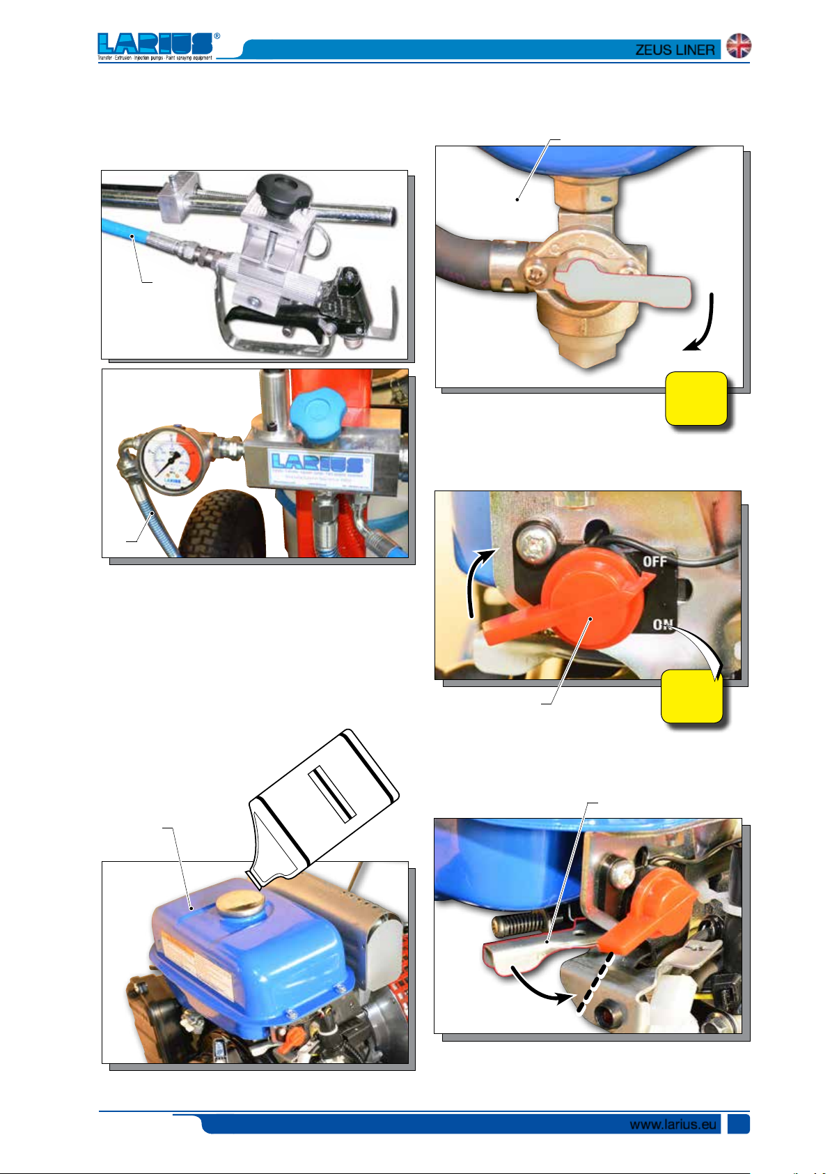
Flexible tube and spray gun connection
• Connect the flexible tube
to tighten the fittings (the use of two wrenches is suggested)
F6
(F6)
to the connector
(F7)
ensuring
• Open the fuel tap (F9) and position it to “ON”.
.
• Put the switch (F10) ON for the equipment.
F9
ON
F7
• It is recommended to use the hose provided with the
standard kit.
NEVER use a damaged or a repaired flexible hose.
NEVER use sealants on fittings’ threads
STARTING THE MOTOR
In order to start the motor, proceed as follows:
• Fill the gasoline tank
F8
(F8)
.
.
FUEL
F10
• Bring the accelerator lever (F11) to about 1/2 of its run.
F11
ON
Ed. 001 - 12/2015
1/2
www.larius.eu
11
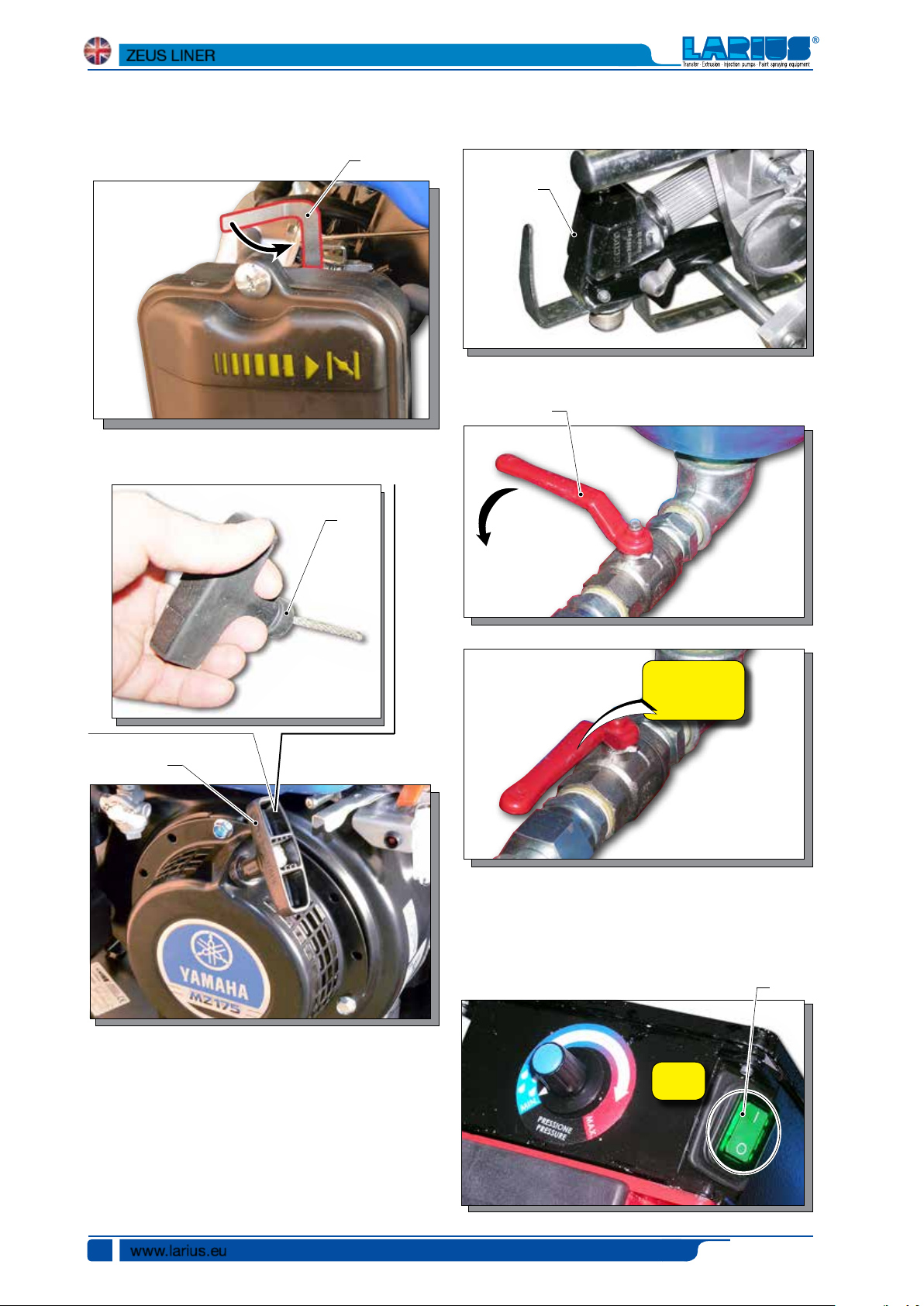
ZEUS LINER
• Pull the lever (F12) for the first cold start up (in position
CHOKE/CLOSE).
F12
• Pull the start up cord (F13).
F13
• Ensure the gun (F14) is without nozzle.
F14
• Open the product output tap (F15).
F15
F13
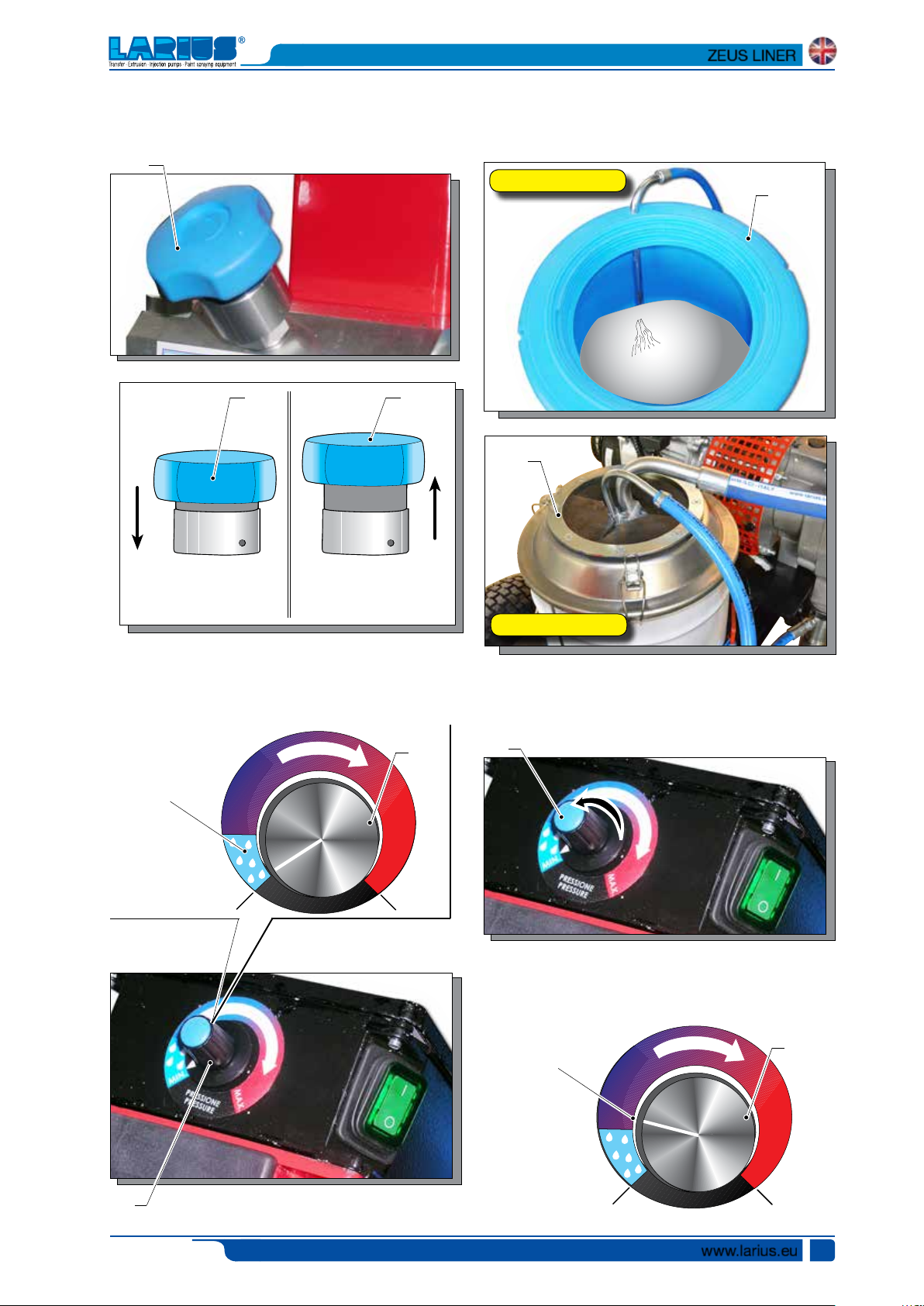
WASHING OF THE NEW EQUIPMENT
• The equipment has already been adjusted at our factory
with light mineral oil left inside the pumping group as
protection. Therefore, wash with diluent before sucking
the product.
OPEN
• Start the motor following the indications provided in the
chapter “STARTING THE MOTOR”.
• Press the switch (F16) of the equipment “ON” (I).
F16
ON
• Lift the suction pipe and dip it into the solvent tank.
• Clean the inside of the tank with a brush.
www.larius.eu
12
Ed. 001 - 12/2015
MIN
X
MIN
X
• Open the recirculating-safety valve (F17).
F17
ZEUS LINER
•
Visually check that the wash fluid starts to re-circulate
within the tank
lt. 50 Tank
F17F17
F19
(F19).
F19
CLOSED
It sprays out of the spray
gun
It re-circulates back into
the tank without spraying
OPEN
• Turn the pressure setting knob (F18) clockwise to the
“CIRCULATION & WASHING” position (drop symbol).
F18
Circulation
and washing
PRESSIONE
PRESSURE
MA
lt. 20 Tank
• Turn the pressure adjustment handle (F18) clockwise to
stop the pump.
• Closed the recirculating-safety valve (F17).
F18
• Turn pressure regulating knob (F18) clockwise a little so
that the machine idles.
F18
Ed. 001 - 12/2015
Minimum
operation
PRESSIONE
PRESSURE
www.larius.eu
F18
MA
13
ZEUS LINER
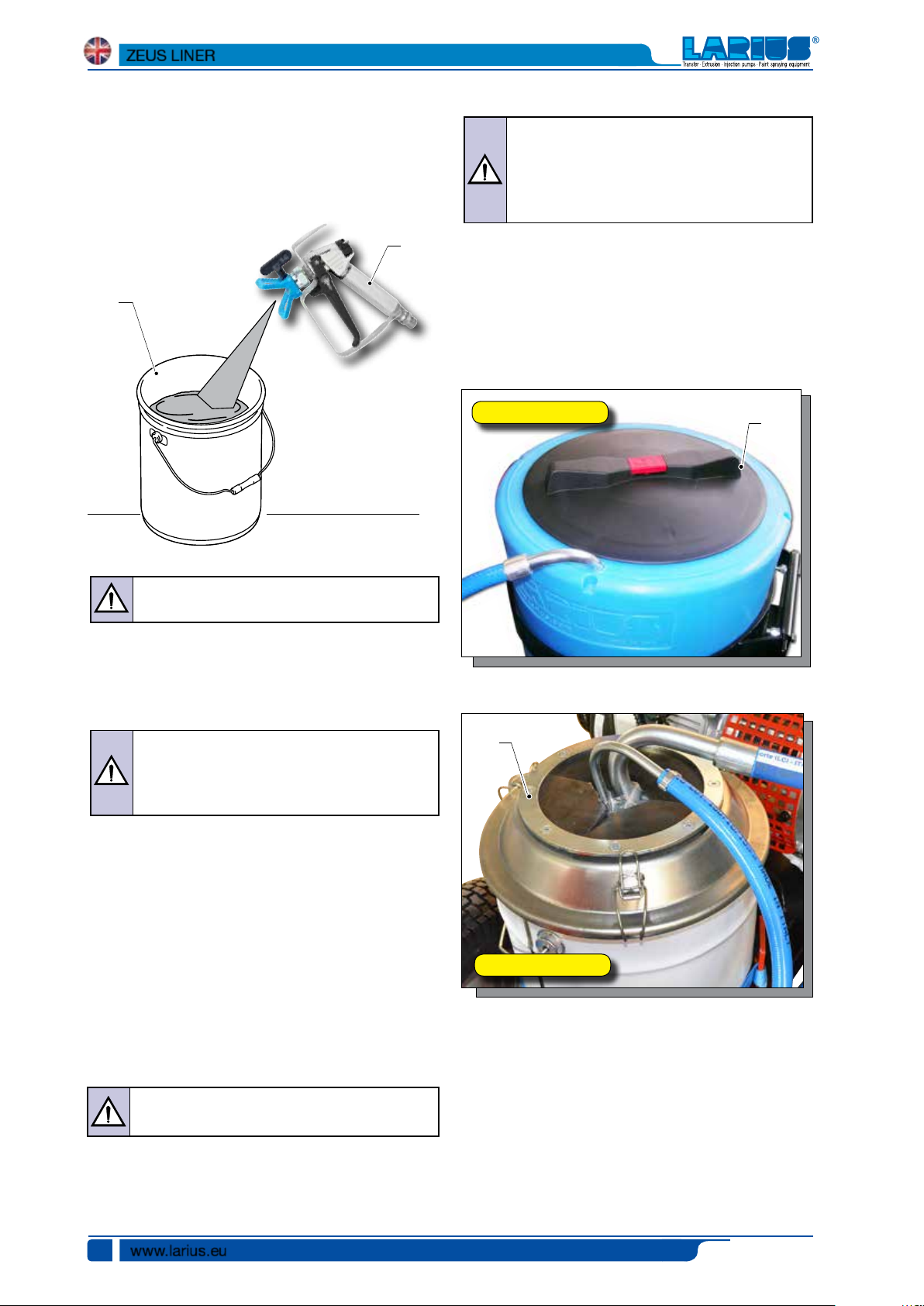
•
Remove the gun (F14) from its support and point it into
a container (F20). Hold the trigger down (to perform the
cleaning) until clean solvent comes out, or else until all of
the wash fluid has been expelled from the tank.
F20
F14
Make sure the product to be used is compatible
with the materials employed for manufacturing
the equipment (stainless steel and aluminium).
Because of that, please contact the supplier of
the product
.
Never use products containing halogen hydrocarbons (as
methylene chloride). If these products come into contact with
aluminium parts of the equipment, can provoke dangerous
chemical reactions with risk of explosion
.
Repeat the same operations with clean solvent if
necessary.
• After having completed the wash operations, bring the
handle to its “MIN” position (F18) and point the gun (F14)
into a collection container (F20) and press the trigger to
release the residual pressure. Release the trigger when
finished.
Absolutely avoid to spray solvents indoors. In
addition, it is recommended to keep away from
the pump in order to avoid the contact between
the solvent fumes and the motor.
• Fill the tank
(F19)
lt. 50 Tank
F19
with the paint.
F19
• Shut off the equipment by turning the switch to its OFF
position “(O)”.
• Stop the combustion engine.
• At this point the machine is ready. If water-based paints
are to be used, after the wash with solvent wash the tank
again with soap and water, then rinse with clean water
(repeating the previously described procedures).
• Insert the manual gun trigger lock and assemble the nozzle.
PRODUCT PREPARATION
MAKE SURE THE PRODUCT IS SUITABLE TO BE
USED WITH A SPRAY GUN.
• Mix and filter the product before using it. For filtration
use CLOSE-MESH and LARGE-MESH LARIUS METEX
braids.
www.larius.eu
14
lt. 20 Tank
Ed. 001 - 12/2015

REGULATIONS
GG
HH
ADJUSTING THE GUN SUPPORT ARM
In order to adjust the position of the spray gun (G1) along the
(X-Y-Z axes) you must operate on the specific regulators (G2-
G3-G4-G5-G6-G7-G8).
Z
ZEUS LINER
G7
G3
G2
Y
G1
X
G8
G5 G4
WORKING
SETUP PROCEDURE
• Use the tooling after performing all the SETTING UP operations above described.
• Check that there is enough petrol.
• Open the product output tap (H1).
H1
Ed. 001 - 12/2015
G6
www.larius.eu
15

ZEUS LINER
• Start the motor following the indications provided in the
chapter “STARTING THE MOTOR”.
• Make sure that the re-circulation/safety valve (H2) is closed
(spray enabled).
H2
CLOSED
Spray enabled
• Press the switch (H3) of the equipment “ON” (I).
• Turn the pressure adjustment handle clockwise until the
desired setting has been reached.
H3
SPRAY ADJUSTMENT
• Slowly turn clockwise the pressure control knob to reach
the pressure value in order to ensure a good atomization
of the product.
• An irregular and marked spray on the sides indicates a low
working pressure. On the contrary, a too high pressure
causes a high fog (“overspray”) and waste of product.
• Pull the lever on the right
(H5) to activate the spray gun
and begin working, advancing the machine in a continuous
manner.
H5
ADJUSTING PUMP UNIT SPEED
• Move the motor acceleration lever (H4) gently to increase
or decrease the speed of the pump.
During the painting operation it is normally recommended to
maintain the position of the accelerator lever (H4) at about 3/4
of its maximum run.
H4
NEVER point the spray gun at yourselves or at
other people. The contact with the casting can
cause serious injuries. In case of injuries caused
by the gun casting, seek immediate medical advice
specifying the type of the product injected.
Recirculating-safety valve: when working at the
maximum pressure available, releasing the gun
trigger sudden increases of pressure can occur.
In this case, the recirculating-safety valve opens
automatically eliminating part of the product from
the recirculating tube.
Then it closes so as to go back to the first working
conditions.
www.larius.eu
16
Ed. 001 - 12/2015

II
CLEANING AT THE END WORK
• Reduce pressure to the minimum (turn counterclockwise
the pressure control knob (I1) ).
ZEUS LINER
• Fill the tank (I2) with wash fluid.
•
Clean the walls of the tank with a brush.
•
Turn the pressure adjustment
to make the machine function at minimum pressure (pump
activated).
(I1)
handle slightly clockwise
• Make sure the re-circulation tube
•
• Place the re-circulation tube back into the tank.
• Keep the gun’s trigger pressed to release any residual
I1
• Release the residual pressure by holding down the trigger
of the gun and pointing it into a container.
• Eliminate the paint remaining within the tank (I2) by placing
the re-circulation tube (I3) into a container.
• Open the recirculating-safety valve (I4).
I4
I2
I3
• Remove the nozzle from the gun and wash it separately.
• Closed the recirculating-safety valve
•
•
(I3)
is inserted into a
container and wait for clean wash fluid to come out of it.
Turn the pressure adjustment handle
stopped).
pressure.
Turn the pressure adjustment handle
to make the machine function at minimum pressure (pump
activated).
Point the manual gun
residual paint and wait for the wash fluid to come out clean
the entire spraying circuit.
I6
(I5)
into a container
(I1)
to minimum (pump
(I1)
slightly clockwise
(I6),
drain the
I5
I3
•
Turn the pressure adjustment
to make the machine function at minimum pressure (pump
activated), until the tank has been completely emptied then
shut off the pump by bringing the handle
position.
Ed. 001 - 12/2015
(I1)
handle slightly clockwise
(I1) to its minimum
• Empty all of the wash fluid from the tank and turn off the
equipment.
•
Turn the pressure adjustment handle
(pump stopped).
• Shut off the motor.
• In case of long storage, we recommend you to suck and
to leave light mineral oil inside the pumping group and the
flexible hose.
Follow the washing procedure before using again
the equipment.
(I1)
to minimum
www.larius.eu
17

JJ
KK
ZEUS LINER
GENERAL MAINTENANCE
D
ischarge the pressure in the pump unit (open
the discharge valve) before carrying out any
maintenance.
DAILY
• Clean the filters;
• Clean the nozzles;
• Clean all the varnish circuit with a specific product;
• Check the fuel motor (see the maintenance table).
PERIODICALLY
• Check the pumping gaskets draft (if the product draws,
replace gaskets);
• Clean the mobile parts from the varnish deposits (spray
guns, etc.);
• Check the gun cables tightening, the wheel block;
• Check that the tubes and all the fittings are correctly locked.
CHECK ON THE PACKING NUT
Daily check the packing nut is tight in order to avoid wastes
but not excessively to prevent the piston from seizing and the
gaskets from wearing.
• Use the lubricant (K1) supplied (ref. 16325) to allow an easy
Daily top up the packing nut.
sliding of the piston inside the gasket group.
ROUTINE MAINTENANCE
Always check that there is oil in the motor.
Check the motor oil every 100 working hours via the relevant
measuring caps positioned on the bottom of the petrol motor.
Top up if necessary.
K1
Rif. 16325
Oil ring
www.larius.eu
18
At the start of each working day check that the
ring nut is full of hydraulic oil (Ref. 16325). This oil
makes it easier for the piston to slide and prevents
any material that escapes via the seal gasket drying
when the equipment is stopped.
Ed. 001 - 12/2015

LL
• For tightening, use the wrench supplied (ref. 11503).
Check the packing nut is tight in order to avoid
wastes but not excessively to prevent the piston
from seizing and the gaskets from wearing.
Ref. 20144
Closing/opening
pin
ZEUS LINER
Oil ring
INCONVENIENTI E RIMEDI
Problem
• The equipment does not start
• On/Off switch disconnected;
• Lack of gasoline;
• Breakdown of motor electric control
box;
• The line of material coming out of the
pump is already under pressure;
• The product is solidified inside the
pump;
Cause
Solution
• Ensure the On/Off switch is on the
“on” position and turn clockwise
the pressure control knob;
• Add gasoline;
• Verify and replace it, if necessary;
• Open the drain valve to release
pressure in the circuit;
• Open the drain valve to release
pressure in the circuit and stop
the machine. Disassemble the
pumping group and the pressure
transmitter and clean;
• The equipment does not suck the
product
Ed. 001 - 12/2015
• Suction filter clogged;
• Suction ilter too fine;
• Product output valve closed;
• The equipment sucks air;
• Clean or replace it;
• Replace it with a larger-mesh filter
(with very dense products, remove
the filter);
• Open the product output valve;
• Check the suction pipe;
www.larius.eu
19

ZEUS LINER
Problem
• The equipment sucks but does not
reach the pressure desired
• When pressing the trigger, the
pressure lowers considerably
Cause
• Lack of product;
• The equipment sucks air;
• The recirculating-safety valve is open;
• The gaskets of the pumping group
are worn;
• Suction or delivery valve dirty;
• Nozzle too big or worn;
• The product is too dense;
• The filter of the gun-butt is too fine;
• Add the product;
• Check the suction pipe;
• Close the recirculating-safety val-
• Replace the gaskets;
• Disassemble the pumping group;
• Replace it with a smaller one;
• Dilute the product, if possible;
• Replace it with a larger-mesh filter;
Solution
ve;
• The pressure is normal but the
product is not atomized
• The atomization is imperfect
• When releasing the trigger of the
gun, the equipment does not stop
(the motor runs slowly and the
piston rod keeps on going up and
down)
• The nozzle is partially clogged;
• The product is too dense;
• The filter of the gun-butt is too fine;
• The nozzle is worn;
• The gaskets of the pumping group
• Suction or delivery valve dirty;
• Clean or replace it;
• Dilute the product, if possible;
• Replace it with a larger-mesh filter;
• Replace it;
• Replace the gaskets;
are worn;
• Disassemble the pumping group
and clean;
www.larius.eu
20
• Recirculating-safety valve defective.
• Verify and replace it, if necessary.
Ed. 001 - 12/2015

MM
ZEUS LINER
CORRECT PROCEDURE OF DECOMPRESSION
• Move the switch (M1) to the OFF (0) position to stop the
equipment.
OFF
M1
• Reduce pressure to the minimum (turn counterclockwise
the pressure control knob (M2)).
• Point the gun (M4) at the receptacle (M5) used to collect
the product and press the trigger to release the pressure.
When completed, activate the safety catch again.
M4
M5
• Open the recirculating-safety valve(M6) to release the
remaining pressure.
M6
M2
• Unlock the safety clamp (M3).
M3
Clamp released
OPEN
Never spray but recirculate
into the tank
WARNING:
If the equipment is still under pressure after performing the operations above described because of
the nozzle or the flexible hose clogged, proceed
as follows:
• Loosen very slowly the gun nozzle.
• Release the clamp.
• Point the gun at the container of the product
and press the trigger to release pressure.
• Loosen very slowly the fitting of connection
from the flexible hose to the gun.
• Clean or replace the flexible hose and the
nozzle.
Ed. 001 - 12/2015
www.larius.eu
21

NN
ZEUS LINER
REPLACEMENT OF THE PUMPING GROUP’S GASKETS
Each time you use the machine, check for material leaking from
the top of the ring nut.
If any material leaks out when the pump is working at the set
pressure, proceed as follows:
• Carry out this operation after cleaning the tooling.
Always disconnect the power supply and release
pressure before going on with the operations
(follow the “correct procedure of decompression).
The gaskets are self-adjusting. If a leak occurs
they must be replaced.
• Disconnect the product feed hose (N1) from the pump unit
by unscrewing the nut (N2).
• Unscrew the fixing ring nut (N3) using the relevant closing
pin (Ref. 20144).
• Release the plastic cover (N4).
• Screw the appropriate supplied tool (N5) (rif. 20213) into
the threaded hole on the holding pin (N6).
Rif. 20213
N5
N4
N6
Rif. 20144
www.larius.eu
22
N3
N2
• Remove the pin (N6) from its seating.
N1
N6
Ed. 001 - 12/2015

ZEUS LINER
• Unscrew the pump unit (N7) from the frontal flange (N8).
N8
N7
Lower seal
• Remove the piston stem (N9) and remove the pump unit
sleeve (N10);
N9
PIT STOP MAINTENANCE
Replacement of upper and lower gaskets 20 minutes.
• Lock the pump unit into a vice and unscrew it with a 50mm
wrench;
•
Release the pump unit from the body of the suction valve;
Countersunk
side
N10
• Grip the stem valve (N11) in a vice;
N11
Ed. 001 - 12/2015
www.larius.eu
23

ZEUS LINER
• Use a size 22 spanner to unscrew the lower stem (N12); • Unscrew the stem valve (N14) altogether, check the surface
of the ball seating (N15) that comes into contact with the
ball (N16).
If worn, replace them;
N16
N12
• Use a screwdriver to remove the two open-ring guide bands
(N13) and replace them;
N13
N15
• Use a screwdriver to remove the O-Ring (N17) and replace
it making sure it is aligned correctly (as illustrated);
N17
www.larius.eu
24
• Screw the valve stem (N14) on again and tighten fully, grip-
ping the valve in a vice. To tighten, use a 22 mm spanner;
the use of a thread paste is recommended;
N14
N14
Ed. 001 - 12/2015

ZEUS LINER
Upper seal
• Remove the ring nut (N18);
• Remove the ring (N19) ;
N21
N18
• Using a screwdriver, extract the second band (N22) located
below the seal (N21) and insert a new band in the same
position;
N22
N19
• Remove the guide band (N20) with a screwdriver and
replace it with a new one;
N20
Channel
extraction
guide ring
The positioning of the seal (N21) equires special
care during assembly.
• Assist insertion by applying leverage to the outside of the
ring (N21), pushing from the outside inwards and helping
the ring to lodge in the seating, while being careful not to
damage the ring’s contact surfaces.
Lubricate with grease before fitting.
N21
• Remove the seal (N21) with a screwdriver;
Ed. 001 - 12/2015
www.larius.eu
25

ZEUS LINER
• Screw the locking ring nut (N18) back onto the body of the
Only if damaged
• Remove the OR (N23-N24) from the body of the foot valve
(N26) and from the ball seat holder (N25) and, if necessary,
replace them.
Reassemble the components in their proper order (as
indicated in the diagram);
N23
N24
N25
pump unit until it makes contact, then loosen it by one turn;
N18
N26
To facilitate fitting the O-ring (N25) it is advisable
to warm it slightly with a blast of hot air.
• Check the integrity of the surface area of the sphere in contact
with the ball (N15). If worn replace the complete detail.
• Remove the sleeve/cylinder seal (N27) and replace it with
a new one;
N16
The ball seating (L17) is countersunk on one side,
where the ball (L18) must sit.
www.larius.eu
26
N27
N15
Ed. 001 - 12/2015

• Check the wear status of the surfaces inside the jacket.
Replace it if necessary;
• Grease the sleeve (N28) using a paintbrush;
N28
ZEUS LINER
N31
N30
Countersink on the jacket
• Insert the sleeve (N28) into the lower pump unit (N29);
N29
N28
Insert the complete piston stem (N30) after greasing
the gaskets (N31);
LUBRICATE
• Screw on the complete foot valve (N26) with the sleeve
assembly (N27);
In order to guarantee a proper seal, tighten the foot
valve (N26) fully, using a 50 mm spanner.
N27
Ed. 001 - 12/2015
N26
www.larius.eu
27

ZEUS LINER
• When refitting the pump unit on the machine, the stem
• Lubricate the upper crown (N36) using oil (N37) (Ref. 16325);
must be at its highest point possible.
• Insert the stem into the connecting rod and insert the fixing
pin (N6).
N6
N37
Rif. 16325
• Tighten the pump casing all the way and, if the delivery pipe
is not correctly aligned, unscrew the pump casing until the
connection is in the correct position before tightening by using
• Refit the inspection barrier (N38);
the ring nut (N32) and the pin (N33) supplied (Ref. 20144).
Oil ring
N36
N38
Closing/opening
N33
N32
• Close the seal ring nut (N35) all the way.
N35
Ref. 20144
pin
• To assemble all the parts in the correct sequence, see the
exploded diagram on page 44.
www.larius.eu
28
Ed. 001 - 12/2015

SPARE PARTS
TT
UU
VV
RR
SS
ZZ
PP
YY
QQ
WW
OO
XX
SPARE PARTS
ZEUS LINER
Complete box
pag. 38
Re-circulation unit
complete
pa. 40
Complete frame
pag. 32
Complete ZEUS LINER
pag. 34
Complete box
trasformer
pag. 38
50l tank
pag. 36
20l tank
pag. 37
Complete mechanical unit
pag. 42
Complete pumping unit
pag. 44
Accessories
pag. 46
Guns arm unit
pag. 41
Complete steering unit
pag. 31
Ed. 001 - 12/2015
www.larius.eu
29

White page intentionally

2
3
1
4
5
COMPLETE STEERING UNIT REF. 4555
OO
WARNING: Always indicate code and quantity for each part required.
ZEUS LINER
10
Pos. Pos.
-
1
2
3
4
5
Code Description Code Description
4555
4735
4841
330058
4737
3637
Complete steering unit
Screw
Screw
Washer
Base
Nut
8
9
6
7
6
7
8
9
10
92038
4253
4736
5339
4739
Spring
Wire stopper
Pin
Washer
Screw
Ed. 001 - 12/2015
www.larius.eu
31

PP
ZEUS LINER
COMPLETE FRAME UNIT REF. 4565 (REF. 4555 INCLUDED)
WARNING: Always indicate code and quantity for each part required.
35
30
29
31
34
32
33
28
27
26
22
21
25
24
23
20
16
17
39
37
19
18
38
1
2
3
4
5
7
8
6
9
15
13
10
11
12
14
36
www.larius.eu
32
Ed. 001 - 12/2015

ZEUS LINER
Pos. Pos.
-
1
2
3
4
5
6
7
8
9
10
11
12
13
14
15
16
17
18
19
Code Description Code Description
4565
4256
4463
4562
8042
4866
7043
32005
4865
4464
4824
7043
32005
4873
3637
34009
4868
4867
8371
4492
96030
4461
4869
4450
Full frame group
Handle
Left lever
Plate
Self-locking nut
Block
Screw
Washer
Handlebar
Right Lever
Plate
Screw
Washer
Complete cable
Nut
Washer
Complete brake
Brake support
Screw
Washers
Wheel
Block
Rod
20
21
22
23
24
25
26
27
28
29
30
31
32
33
34
35
36
37
38
39
-
26020
4429
4490
95156
95096
4732
4566
4872
4265
4559
20450
95156
81033
95096
20537
4864
4873
18026
4448
4833
11210
8079
Pointer unit
Gun support
Block
Screw
Washer
Pivoting wheel
Primary plate
Plate
Wire lock
Motor plate
Cable fastener Gj1/4
Screw TE M10x30
Washers
Anti-vibration 50x30 m10
Frame
Cable complete with control
Compensation tube 1/4” 15m rac.
M16x1.5
Complete spray gun support unit
Fast Clean small Liner accessory
Complete spray gun AT 250
Technical data plate
Ed. 001 - 12/2015
www.larius.eu
33

QQ
ZEUS LINER
COMPLETE ZEUS LINER REF. 4554
WARNING: Always indicate code and quantity for each part required.
27
8
26
20
21
22
23
25
9
24
19
28
1
2
3
45
6
7
29
10
11
12
30
18
17
13
14
15
16
www.larius.eu
34
Ed. 001 - 12/2015

ZEUS LINER
Pos. Pos.
-
1
-
2
3
4
5
6
7
8
9
10
11
12
13
14
15
Code Description Code Description
4554
4889
18392
4244
4887/1
4886
96031
34009
4888/1
4885/1
4435
96031
32032
4558
96080
4556
34009
Complete ZEUS LINER unit
Motor
Yamaha MZ 175 motor exhaust kit
Tab
Flange
Tightening rod
Screw
Washer
Cover
Bush
Tab
Screw
Screw
Pinion
Nut
Spacer
16
17
18
19
20
21
22
23
24
25
26
27
28
29
30
-
Washer
5783
4557
20531
4416
4882/1
4883
4884
95158
54004
32005
81107
34009
69016
96031
4553
16656
16325/1
Screw M8x80
Reduction flange
Fan
Complete clutch MK3
Washer
Bearing
Spacer
Nut
Screw
Washer
Vibration-damping pad 40x30 M8
Washer
Screw
Screw
Zeus Liner reduction unit
Warning tags
Ed. 001 - 12/2015
www.larius.eu
35

RR
ZEUS LINER
COMPLETE 50L TANK REF. 4895
WARNING: Always indicate code and quantity for each part required.
1
2
3
4
17
12
13
14
15
16
Pos. Pos.
Code Description Code Description
5
6
7
8
9
1011
-
1
2
3
4
5
6
7
8
9
www.larius.eu
36
4895
18249/1
85014
18231
18249
18246
3637
96030
901568
4894
Complete 50L Tank
Cover
Filter
Support
50L Tank
Support
Nut
Washer
Screw
Support
10
11
12
13
14
15
16
17
96030+
32024/1
901568
20833
8375
30532
95032
96099
4834
Washers
Screw
Elbow
Union
Valve
Union
Seal
Complete suction+output system
Ed. 001 - 12/2015

1
5
6
7
8
COMPLETE 20L TANK REF. 4890
SS
WARNING: Always indicate code and quantity for each part required.
2
3
4
10
ZEUS LINER
11
9
Pos. Pos.
-
1
2
3
4
5
Code Description Code Description
4890
4314
52017
4308
4309
4109
Complete 20L Tank
Screw
Nut
Ring
Rubber
Cover
6
7
8
9
10
11
4064
4274
69014
4250
4111
16676
20l Tank
Belt
Screw
Base
Cover complet
Complete suction+output system
Ed. 001 - 12/2015
www.larius.eu
37

1
TT
ZEUS LINER
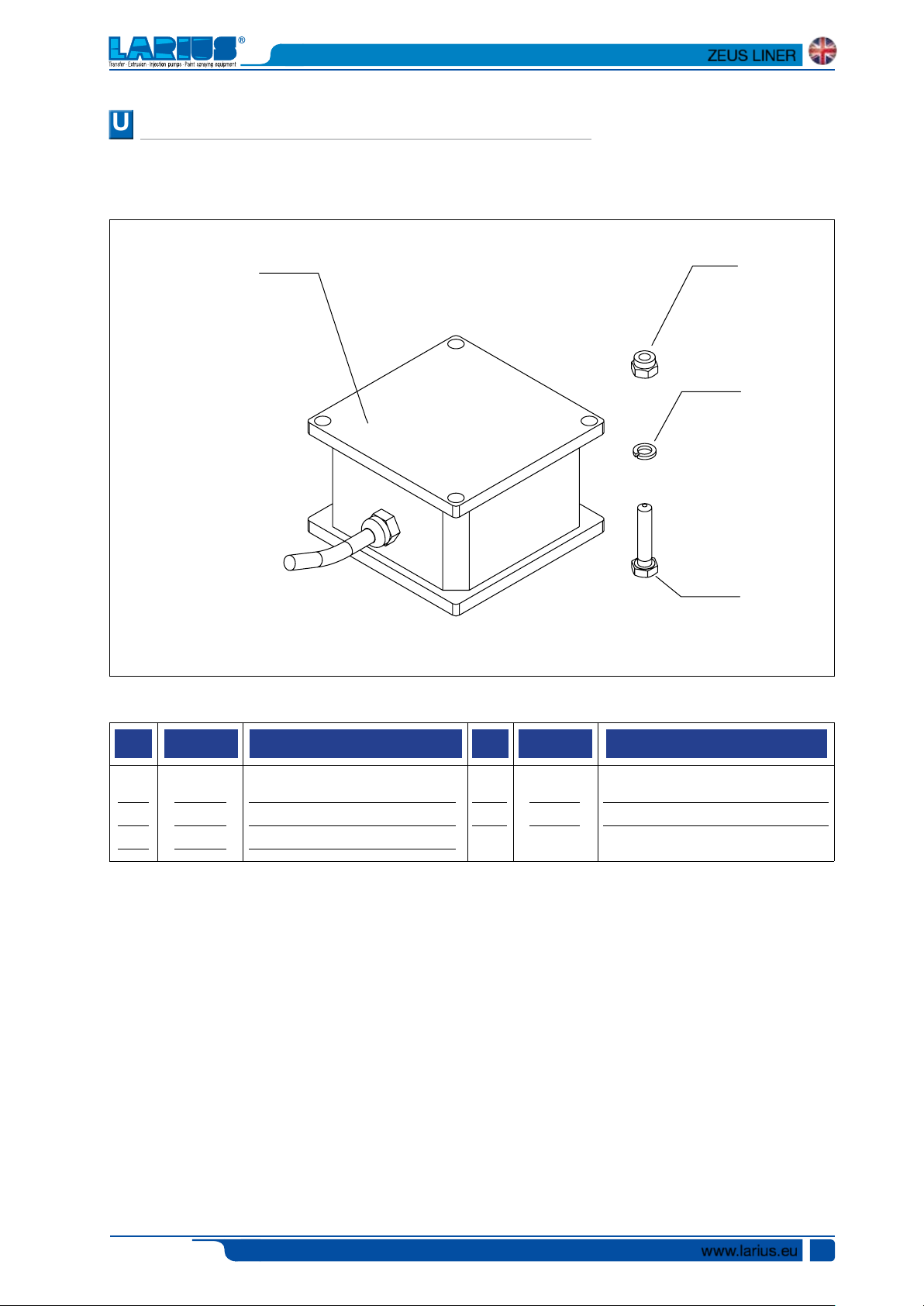
COMPLETE BOX REF. 4896
WARNING: Always indicate code and quantity for each part required.
2
3
5
4
Pos. Pos.
-
1
2
3
4
Code Description Code Description
4896
91062
5933
30549
8042
Complete box
Screw
Switch ON/OFF
Potentiometer
Nut
5
6
32005
16850
Washer
Warning stickers
www.larius.eu
38
Ed. 001 - 12/2015
2
1
4
COMPLETE BOX TRASFORMER REF. 4845
UU
WARNING: Always indicate code and quantity for each part required.
ZEUS LINER
3
Pos. Pos.
-
1
2
Code Description Code Description
4845
8042
32005
Complete box transformer
Nut
Washer
3
4
91062
4846
Screw
Transformer box
Ed. 001 - 12/2015
www.larius.eu
39

16
15
14
13
10
11
10
12
VV
ZEUS LINER
RE-CIRCULATION UNIT COMPLETE REF. 4893
WARNING: Always indicate code and quantity for each part required.
1
2
17
3
4
9
8
7
6
Pos. Pos.
-
1
2
3
4
5
6
7
8
9
Code Description Code Description
4893
4891
18692
18689
33004
33005
56534
56535
16205
18627
Re-circulation unit complete
Cover
Sensor
Or Seal
Screw
Washer
Plug
Seal
Filter
Sieve
10
11
12
13
14
15
16
17
18
-
96206
18614
4892
16400
32005
91062
18871
18684
18657
16854
5
18
Union
Union
Base
Valve
Washer
Screw
Cable fastener
Copper gasket
Pressure label
Warning stickers
www.larius.eu
40
Ed. 001 - 12/2015

WW
GUNS ARM UNIT REF. 26011
WARNING: Always indicate code and quantity for each part required.
ZEUS LINER
15
16
11
12
13
9
8
7
6
9
8
5
4
3
Note: DEPENDING ON THE USE, SELECT
THE ARM HOISTING MECHANISM THAT IS
SUITABLE.
TO MOUNT THE MANUAL ARM HOIST ADD THE
FOLLOWING CODES TO THE UNIT:
- GENOVESE CHAIN REF. 18456, 0.7 M
- HOOK REF. 18457 X 2 PCS.
8
10
16
17
18
1
2
14
Pos. Pos.
-
1
2
3
4
5
6
7
8
9
Ed. 001 - 12/2015
Code Description Code Description
26011
26012
23444
4757
91062
26013
95083
26015
510026
8385
Guns arm unit
Guns arm
Pivoting wheel 160/40-80
Hinge complete with pin
Screw TCE UNI M6x20
Joint for gun arm
Screw TCE UNI M12x40
Joint to connect gun arm
Washer ø 8
Screw UNI M8x30
10
11
12
13
14
15
16
17
18
3637
32005
20539
95096
96080
26017
26972
95666
95013
Self-locking nut M8
Washer Schnor ø 6
Screw TE UNI M10x75
Washer Grower ø 10
Self-locking nut M10
Joint pin
Bush
Flat washer ø 16
Self-locking nut M16
www.larius.eu
41

XX
ZEUS LINER
COMPLETE MECHANICAL UNIT
WARNING: Always indicate code and quantity for each part required.
2730
20
1
5A
5B
5A
32
3
3A
3B
3A
29
3
4
7
6
5
4
9
8
34
5
6
12
17
10
11
14
13
15
1416
www.larius.eu
42
31
243537
33
26
21
2
25
18
rif.5010
Earth cable
rif.20213
Plug extractor
19
Ed. 001 - 12/2015
36
23
29
22
37

ZEUS LINER
Pos.
-
1
2
3
3A
3B
4
5
5A
5B
6
7
8
Code Description Code Description
35144
30201
34009
20250
Complete mechanical unit
Flange motor
Washer Ø 8
INA Thrust bearing
complete
20251
20252
20253
30254
30255
30256
30257
20205
20204
Fifth wheel
Cage
INA Roller bearing
Thrust
Fifth wheel
Cage
INA Roller bearing
Toothed wheel court
Court toothed
Q.tà
Pos. Q.tà
18
19
20
21
22
23
24
25
26
27
28
29
30
31
30263
30210
20264
30665
30266
5378
30211
30212
69011
30202
35141
30214
35143
34020
Positioning spring
Pump unit pivot
Centring pin Ø 6X20
Guide bushing
Scraper
Screw M4X10
Inspection hatch
Tin plate door
Screw M8X20
Reduction unit cover
Cover assembly
Fixing ring
Front sticker
Rivet Ø 2 mm
1
1
6
2
4
2
2
2
4
2
2
1
1
1
1
2
1
1
2
1
1
2
1
1
1
1
6
9
10
11
12
13
14
15
16
17
20258
20207
30206
30259
30272
30208
30209
30261
30262
Toothed driving assembly
Eccentric sprocket
Eccentric cam
Cam assembly
Spacer pin Ø 6X10
Guide bushing
Connecting rod
INA Roller bearing
Complete connecting rod
32
33
34
35
36
37
38
21688
20245
96211
30274
30666
30225
20278
Plug
Screw M4X10
Screw M6X10
Warning stickers
Tightening ring
Fixing ring
Cylindrical pin
1
1
1
1
1
1
1
1
1
1
1
1
2
1
1
1
Ed. 001 - 12/2015
www.larius.eu
43

YY
ZEUS LINER
COMPLETE PUMPING UNIT
WARNING: Always indicate code and quantity for each part required.
27
CORRECT
FITTING
LABBRO
38
21
26
25
40
24
23
22
20
19
ZEUS
Tightening pin
Ref.20144
Complete intake tube
and recirculation
Ref. 35161
39
9
31
32
33
37
42
11
10
CORRECT
FITTING
18
17
15
14
13
12
16
41
8
7
6
5
30
29
28
35
36
4
3
2
34
1
www.larius.eu
44
Ed. 001 - 12/2015

ZEUS LINER
Pos.
-
-
-
-
-
-
1
2
3
4
5
6
7
8
Code Description Code Description
35110
35111
Complete standard pump unit
Complete pumping with
suction hose
35112
35113
35114
35161
37216
35118
37229
35115
35116
35163
35138
35121
Foot valve seal kit
Complete seal kit
Jacket+piston kit
Suction hose kit + recirculation
Suction filter
Hard suction hose
Connection
Foot valve
Assembled at Ball
Ball Ø 3/4”
Ball guide
OR 3156
Q.tà
Pos. Q.tà
19
20
21
22
23
24
25
26
27
28
29
30
31
32
35133
35134
95230/1
35135
30142
30139
30138
30114
30113
35162
35119
96836/2
98374
98376
Sleeve
Seal
Adapter 3/8 AP M-M
Pump unit casing
67806-X0220-56Z
EAR 148856-02
67806-X0220-A22Z
Tightening ring nut
Stuffing nut
OR 3087
Accommodation ball seat
See ball
Elbow joint F-F Gj 3/4
Suction fitting Jas
M-M Gc 3/4 - M36x2
-
-
-
-
-
1
1
1
1
1
1
1
1
1
1
1
1
1
1
1
1
1
1
1
1
1
1
9
10
11
12
13
14
15
16
17
18
35122
35124
7062
35125
7071
35151
35154
35157
35129
37180
35131
OR 3206
Valve stem
See ball
Complete valve stem
Ball Ø 9
Ring female lower
Polyethylene gasket
PTFE gasket
Lower stem
O-Ring
Upper stem
33
34
35
36
37
38
39
40
41
42
96099
35139
35117
35123
35132
35136
35137
30122
35142
35159
Seal sleeve
Assembly float rigid
Assembly the valve seat F
Assembly the group see fund
Assembly the stem
Assembly cylinder
Suction hose Assembly kit
Ring seal top awards
Ring male
lower
Pack lower packing
1
1
1
1
1
1
1
1
1
1
2
2
1
1
1
Ed. 001 - 12/2015
www.larius.eu
45

ZZ
ZEUS LINER
ACCESSORIES
Code Description
Cod. 11250: AT 250 1/4"
Cod. 11200: AT 250 M16x1,5
35017
High pressure hose mt. 10 - 1/4"
Art. 16675: Suction system
Art. 16200: LINE FILTER
Art. 270: FILTER 100 MESH
Art. 271: FILTER 60 MESH
PISTON GUNSTOCK FILTERS
Code 11039: Green (30M) - Code 11038: White (60M)
Code 11037: Yellow (100M) - Code 11019: Red (200M)
Art. 4405:
PEARLIZED REFLECTING PAINT DISTRIBUTION KIT
Art. 16802: FILTER 30 MESH
www.larius.eu
46
Ed. 001 - 12/2015

TOP-SPRAYING CLEAN
UGELLO TOP-SPRAYING CLEAN
nozzles code
TSC 7-20
TSC 7-40
TSC 9-20
TSC 9-40
TSC 11-20
TSC 11-40
TSC 13-20
TSC 13-40
TSC 13-60
TSC 15-20
TSC 15-40
TSC 15-60
TSC 17-20
TSC 17-40
TSC 17-60
ZEUS LINER
TSC 19-20
TSC 19-40
TSC 19-60
TSC 21-20
TSC 21-40
TSC 21-60
TSC 23-20
TSC 23-40
TSC 23-60
TSC 27-20
TSC 27-40
TSC 27-60
TSC 31-40
TSC 31-60
Art. 18280: JOINT
SUPER FAST-CLEAN
Art. 18270: SUPER FAST-CLEAN base UE 11/16x16
UGELLO SUPER FAST-CLEAN
SFC07-20
SFC07-40
SFC09-20
SFC09-40
SFC11-20
SFC11-40
SFC13-20
SFC13-40
SFC13-60
SFC15-20
SFC15-40
SFC15-60
SFC17-20
SFC17-40
SFC17-60
SFC19-20
SFC19-40
nozzles code
SFC19-60
SFC21-20
SFC21-40
SFC21-60
SFC23-20
SFC23-40
SFC23-60
SFC25-20
SFC25-40
SFC25-60
SFC27-20
SFC27-40
SFC27-60
SFC27-80
SFC29-20
SFC29-40
SFC29-60
SFC29-80
SFC31-40
SFC31-60
SFC31-80
SFC33-40
SFC33-60
SFC33-80
SFC39-40
SFC39-60
SFC39-80
SFC43-40
SFC43-60
SFC43-80
SFC51-40
SFC51-60
SFC51-80
Ed. 001 - 12/2015
Art. 18280: JOINT
Art. 18270: SUPER FAST-CLEAN base UE 11/16x16
www.larius.eu
47

ZEUS LINER
HIGH PRESSURE HOSE 3/8" M16x1,5 pressure max. 425 bar
Art.
18063: 7,5 mt
Art.
18064: 10 mt
Art.
18065: 15 mt
ANTISTATIC HOSE 3/16" M16x1,5 pressure max. 210 bar
Art.
6164: 5 mt
Art.
55050: 7,5 mt
Art.
35018: 10 mt
ANTIPULSATIONS 1/4" - M16x1,5
pressure max. 250 bar
Art.
35013: 5 mt
Art.
35014: 7,5 mt
Art.
35017: 10 mt
Art.
18026: 15 mt
Code
147: HIGH PRESSURE GAUGE M16X1,5
Code
150: HIGH PRESSURE GAUGE GJ 1/4”
Code 35185: PUMPING UNIT COMPLETE REPAIRING KIT
www.larius.eu
48
Code
10156: SWIVEL CONNECTION FOR PLA 1/4"
Code
10159: SWIVEL CONNECTION FOR PLA M16x1,5
Ed. 001 - 12/2015

ZEUS LINER
GUN EXTENSION
Art. 153: cm 30 -Art. 153: cm 40
Art. 155: cm 60 - Art. 158: cm 80 - Art. 156: cm 100
PLA 1/4”
+ BASE SUPER FAST-CLEAN
Art. K11446-K11441-K11436: cm 240-180-130
PLA M16x1,5
+ BASE SUPER FAST-CLEAN
Art. K11445-K11440-K11435: cm 240-180-130
MX 850
MX 1100
Art. 16780: TELESCOPIC PAINT ROLLER
complete with:
n. 1 Roller with extra-long fiber
n. 1 Roller with long fiber
n. 1 Roller with medium fiber
Flexible hose mt. 2 3/16 " M16x1,5
MX 1100 ER
Art. 217550: MX 850 - Art. 217560: MX 1000 - Art. 217570: MX 1100 ER
Ed. 001 - 12/2015
www.larius.eu
49

LINE STRIPERS
MIRO’ LINER
LINER 3000
LARIETTE LINER 2000
VIKING LINER
DRAGON LINER SEMOVENTE
K2 LINER
EVEREST TH SEMOVENTE
DALÌ LINER
MANUFACTURER:
23801 CALOLZIOCORTE - LECCO - ITALY - Via Antonio Stoppani, 21
Tel. (39) 0341/62.11.52 - Fax (39) 0341/62.12.43
E-mail: larius@larius.com - Internet http://www.larius.com
DIRECT LINE
CUSTOMERS TECHNICAL SERVICE
Tel. (39) 0341/621256
Fax (39) 0341/621234
 Loading...