


11 - 12
ZEUSZEUS
005
Ed.
P A I N T S P R A Y I N G E Q U I P M E N T
OPERATING AND
OPERATING AND
MAINTENANCE INSTRUCTION
MAINTENANCE INSTRUCTION
ENGLISH

Due to a constant product improvement programme, the factory reserves the right to modify technical
details mentioned in this manual without prior notice.
This manual is to be considered as an English language translation of the original manual in Italian.
The manufacturer shall bear no responsibility for any damages or inconveniences that may arise due
to the incorrect translation of the instructions contained within the original manual in Italian.

ZEUS
ELECTRIC PISTON PUMP
ELECTRIC PISTON PUMP
English
INTRODUCTION .................................................. p.1
WARNINGS .......................................................... p.2
WORKING PRINCIPLE ........................................ p.3
A
TECHNICAL DATA ................................................ p.4
B
DESCRIPTION OF THE EQUIPMENT ................. p.5
C
Alarm messages .............................................. p.7
Functions table ................................................. p.7
Alarm message table ....................................... p.8
TRANSPORT AND UNPACKING ......................... p.8
D
SAFETY RULES ................................................... p.9
E
Electrical safety precautions ............................ p.10
SETTING-UP ........................................................ p.10
F
Connection of the flexible hose to the gun ....... p.10
Check on power supply .................................... p.10
Connection of the tooling to the power
supply ............................................................... p.12
Washing of the new equipment ........................ p.12
Preparing the product ..................................... p.13
WORKING ............................................................ p.14
G
Start of the working operations ........................ p.14
Spray adjustment ............................................. p.16
CLEANING AT THE END OF THE WORK ........... p.16
H
Cleaning for solvent-based products ................ p.16
Cleaning for water-based products .................. p.19
I
ROUTINE MAINTENANCE .................................. p.22
Check on the packing nut ................................. p.22
Checking the heat exchange radiator............... p.23
Checking the seal gasket (o-ring) .................... p.23
PROBLEMS AND SOLUTIONS ........................... p.24
J
CORRECT PROCEDURE OF
K
DECOMPRESSION .............................................. p.25
L
REPLACEMENT OF THE PUMPING
GROUP’S GASKETS ........................................... p.26
Pit stop maintenance........................................ p.27
Lower seal ........................................................ p.27
Upper seal ........................................................ p.29
SPARE PARTS
COMPLETE ELECTRO-MECHANICAL
M
UNIT ..................................................................... p.34
N
BASIC HYDRAULIC BLOCK REF. 30400 ............. p.36
O
COMPLETE PUMPING ELEMENT ...................... p.38
P
ELECTRICAL CONTROL - EXPLODED VIEW .... p.40
Q
CARRIAGE ........................................................... p.42
R
ELECTRIC MOTOR .............................................. p.43
S
ACCESSORIES .................................................... p.44
WE ADVISE THE USE OF THIS EQUIPMENT ONLY BY PROFESSIONAL OPERATORS.
ONLY USE THIS MACHINE FOR USAGE SPECIFICALLY MENTIONED IN THIS MANUAL.
Thank you for choosing a LARIUS S.R.L. product.
As well as the product purchased,
you will receive a range of support services
enabling you to achieve the results desired,
quickly and professionally.
1
ZEUS
English
WARNINGS
Read this operator’s manual carefully before using the equipment.
An improper use of this machine can cause injuries to people or things.
Do not use this machine when under the influence of drugs or alcohol.
Do not modify the equipment under any circumstances.
Use products and solvents that are compatible with the various parts of the equipment, and read the manufacturer’s warnings carefully.
See the Technical Details for the equipment given in the Manual.
Check the equipment for worn parts once a day. If any worn parts are found, replace them using ONLY original spare parts.
Keep children and animals away from work area.
Comply with all safety standards.
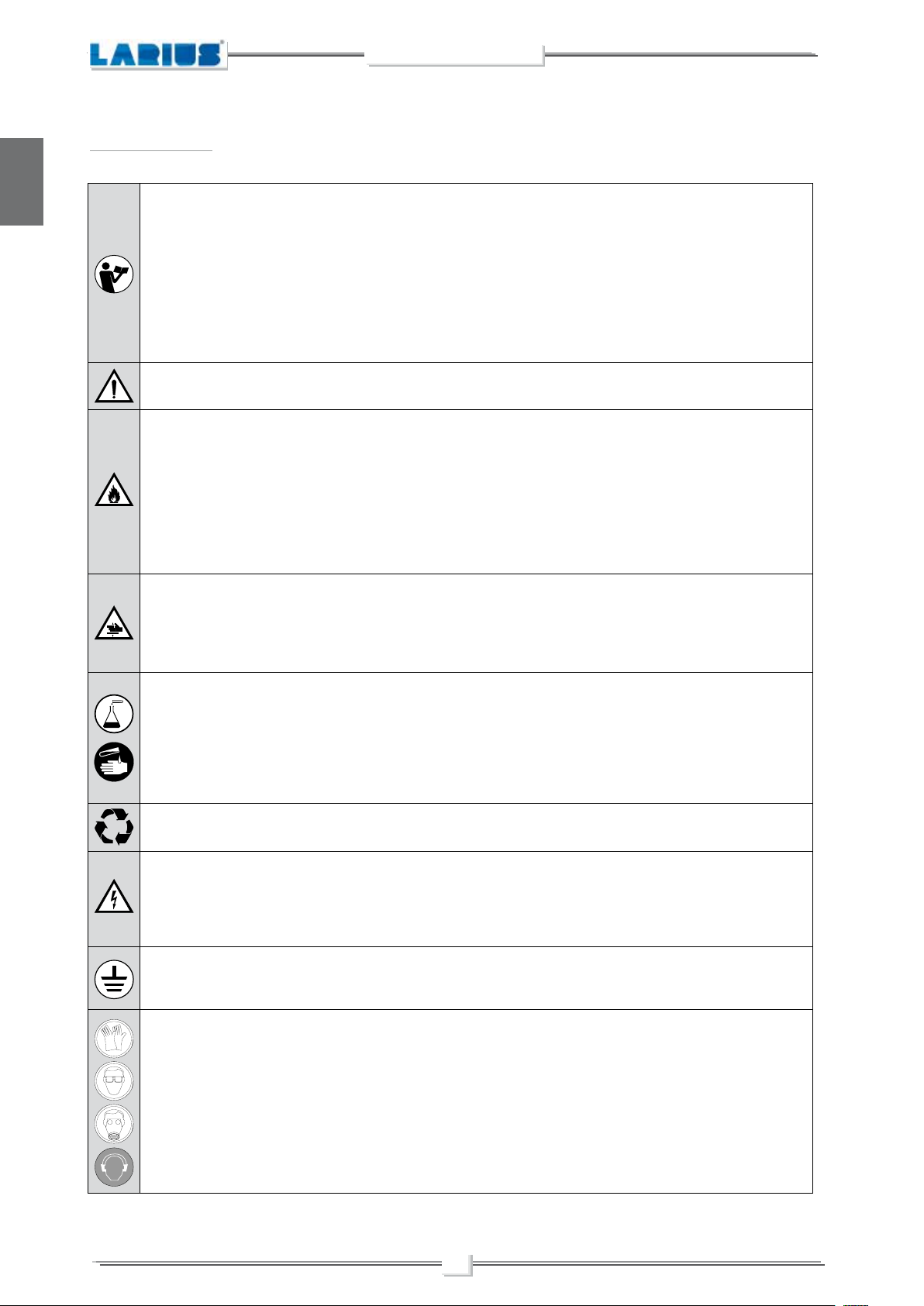
It indicates an accident risk or serious damage to equipment if this warning is not followed.
It indicates a fire or explosion risk if this warning is not followed.
Eliminate all ignition sources such as pilot lights, cigarettes, portable electric lamps and plastic drop cloths.
Keep work area free of debris.
ONLY use this equipment in a well ventilated area.
EARTH ALL THE EQUIPMENT LOCATED IN THE WORK AREA.
Do not form connections or switch light switches on or off if the air contains inflammable fumes.
If electrical shocks or discharges are encountered the operation being carried out using the equipment must be stopped immediately.
Keep a fire extinguisher at hand in the immediate vicinity of the work area.
The table below provides the meaning of the symbols used in this manual in relation to using, earthing,
operating, maintaining, and repairing of this equipment.
It indicates wound and finger squashing risk due to movable parts in the equipment.
Tenersi lontano dalle parti in movimento.
Do not use the equipment without the proper protection.
Before any inspection or maintenance of the equipment, carry out the decompression procedure explained in this manual, and prevent
any risk of the equipment starting unexpectedly.
Report any risk of chemical reaction or explosion if this warning has not been given.
There is a risk of injury or serious lesion related to contact with the jet from the spray gun. If this should occur, IMMEDIATELY contact
a doctor, indicating the type of product injected.
Do not spray before the guard has been placed over the nozzle and the trigger on the spray gun.
Do not put your fingers in the spray gun nozzle.
Once work has been completed, before carrying out any maintenance, complete the decompression procedure explained in this manual.
It indicates important recommendations about disposal and recycling process of products in accordance with the environmental regulations.
Report any danger of electric shock if the warning and presence of live electrical parts has not been indicated.
Store in a dry place and do not expose to the rain.
Check that the cables are in good condition.
Switch off the equipment and discharge any electricity before cleaning or maintaining the equipment.
Mark any clamps attached to earth cables.
Use ONLY 3-wire extension cords and grounded electrical outlets.
Before starting work make sure that the electrical system is earthed and that it complies with safety standards.
It is obligatory to wear suitable clothing as gloves, goggles and face shield.
Wear clothing that complies with the safety standards in force in the country in which the equipment is used.
Do not wear bracelets, earrings, rings, chains, or anything else that may hinder the operator’s work.
Do not wear clothing with wide sleeves, scarves, ties, or any other piece of clothing that could get tangled up in moving parts of the
equipment during the work, inspection, or maintenance cycles.
2
ZEUS
A
WORKING PRINCIPLE
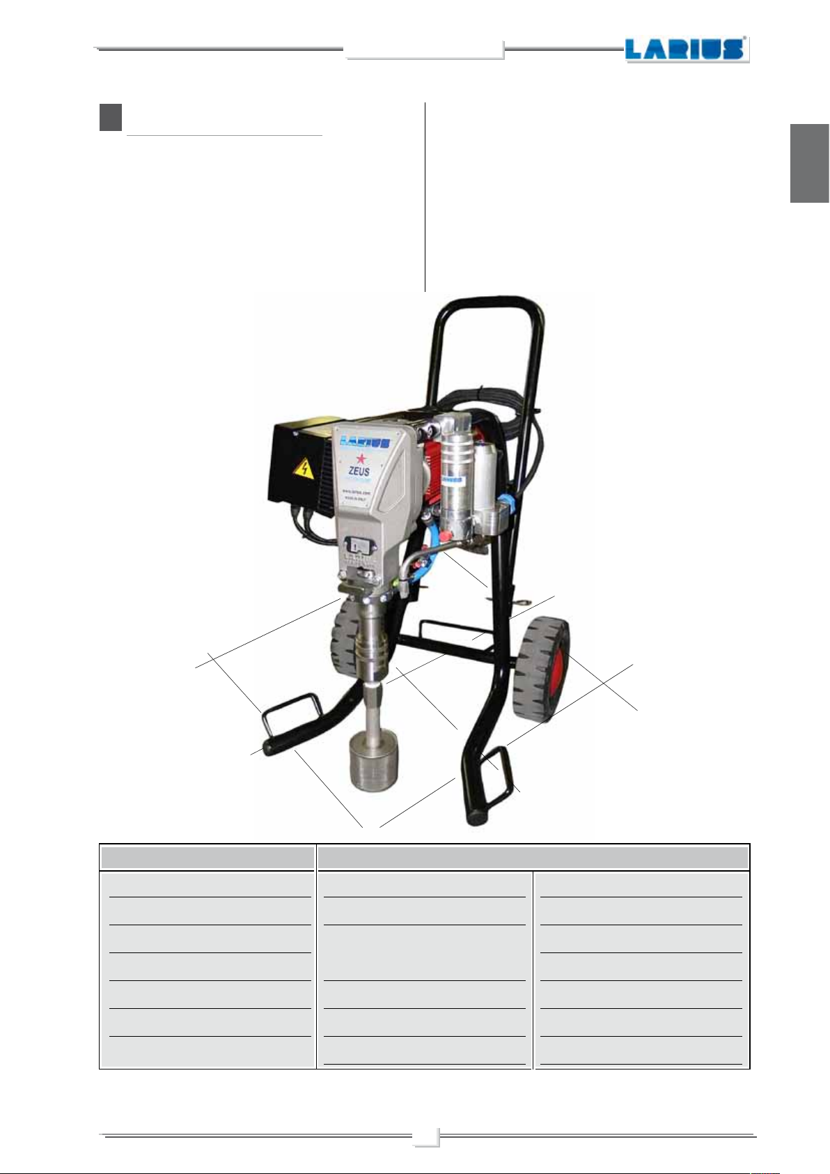
The DRAGON unit is defined “electric piston pump”.
An electric piston pump is used for high pressure painting without
air (from this process derives the term ”airless”).
The pump is controlled by an electric motor coupled with a reduction gear.
A cam shaft and a connecting rod allow to obtain the reciprocating
motion necessary to the working of the “pumping group” piston.
The piston movement produces a “vacuum”.
The product is sucked, pushed towards the pump outlet and then
English
sent to the gun through the flexible hose.
An electronic device located next to the reduction box, is used to
regulate and control the pressure of the material leaving the pump.
When the pump reaches the set value, the motor stops and starts
again when the value decreases.
A safety valve avoiding overpressure, guarantees the total reliability
of the equipment.
Fields of application
Indoor
Outdoor
Industrial buildings
Industrial constructions
Redeveloping
Roofing
Application materials
Top-coat plaster
Self-levelling plasters
Pre-mixed plasters (granulome-
try 0,0)
Stuccos
Plasters
Fillers
3
Intumescents
Encapsulators
Insulation
Water proofing
Elastomers
Epoxi resins
Bitumen
B
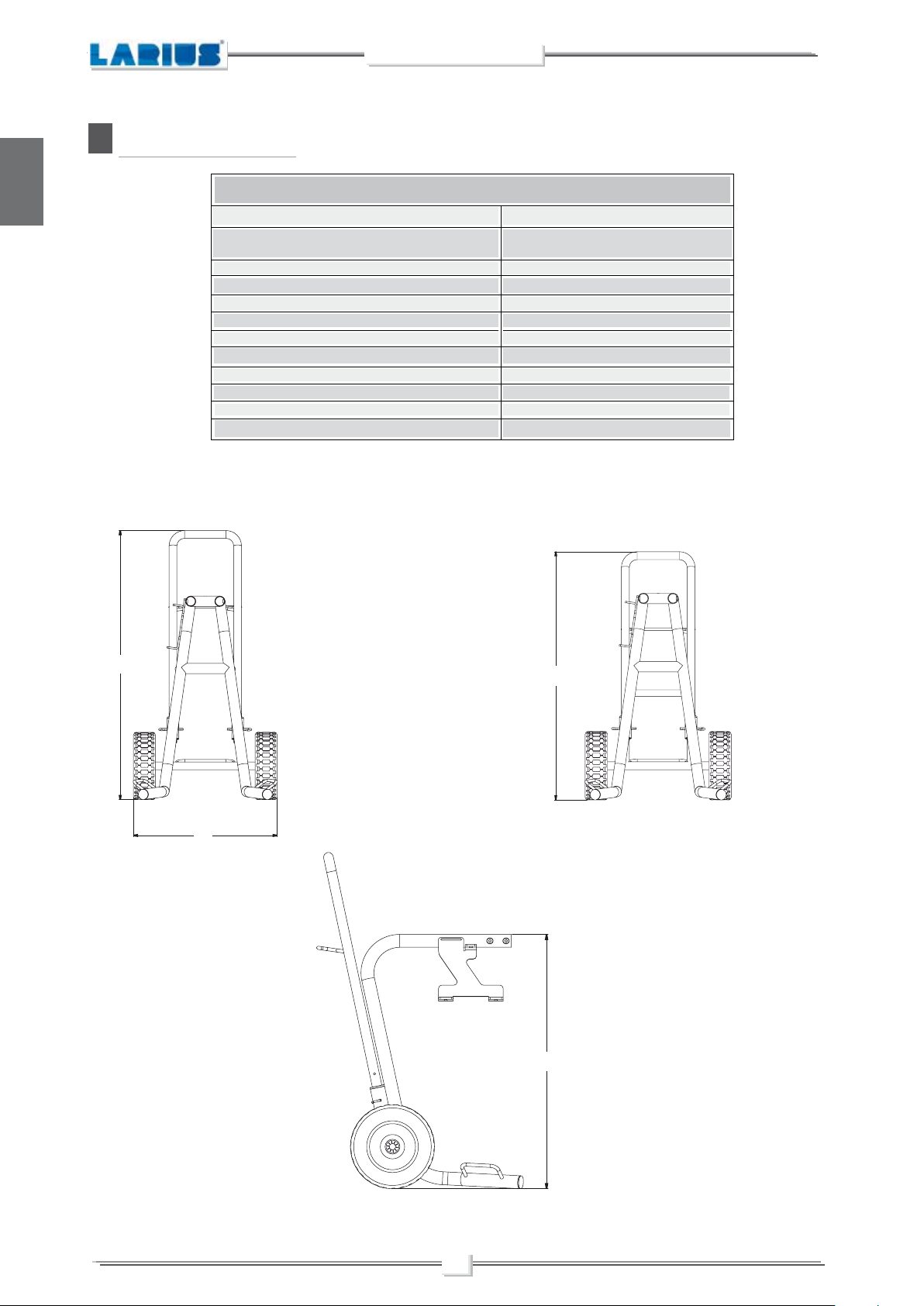
TECHNICAL DATA
ZEUS
English
ZEUS
ASUPPLY (single-phase)*
RUN GENERATOR SUPPLY
(single-phase)
MOTOR POWER
MAX. WORKING PRESSURE
MAX. DELIVERY
MATERIAL OUTLET
WEIGHT
LEVEL OF THE SOUND PRESSURE
MINIMUM WIDTH
MINIMUM HEIGHT
MAXIMUM HEIGHT
MINIMUM ENCUMBRANCE
*Available on request with special voltages
Parts of the pump in contact with the material Stainless Steel AISI 420B, Teflon
230V C.A. 50Hz
9 Kw
M16 x 1,5 (M)
PTFE
; Aluminium
casynchronous
2 kW
230 bar
4 L/min
58 Kg
≤ 60dB(A)
(A) 560 mm
(B) 945 mm
(C) 1040 mm
(D) 790 mm
, Galvanised steel
C
B
A
D
4
ZEUS
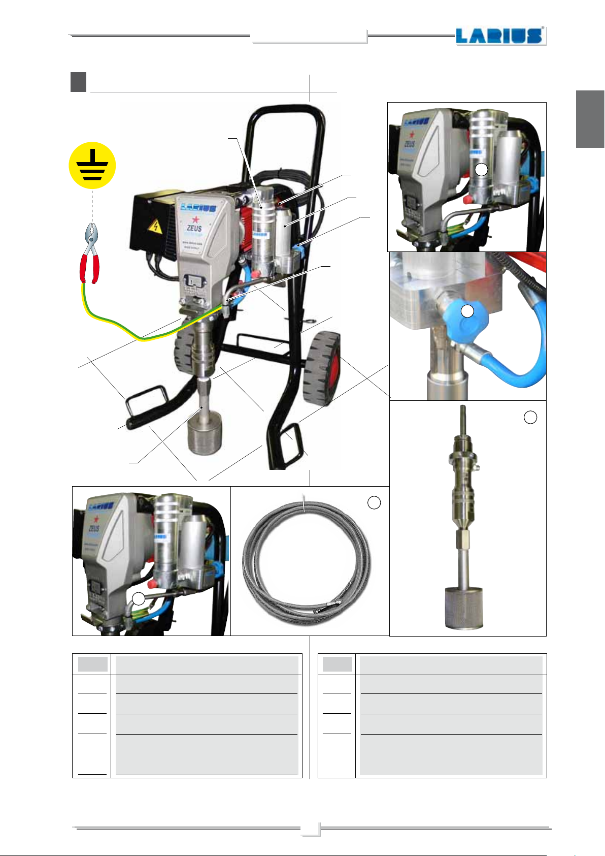
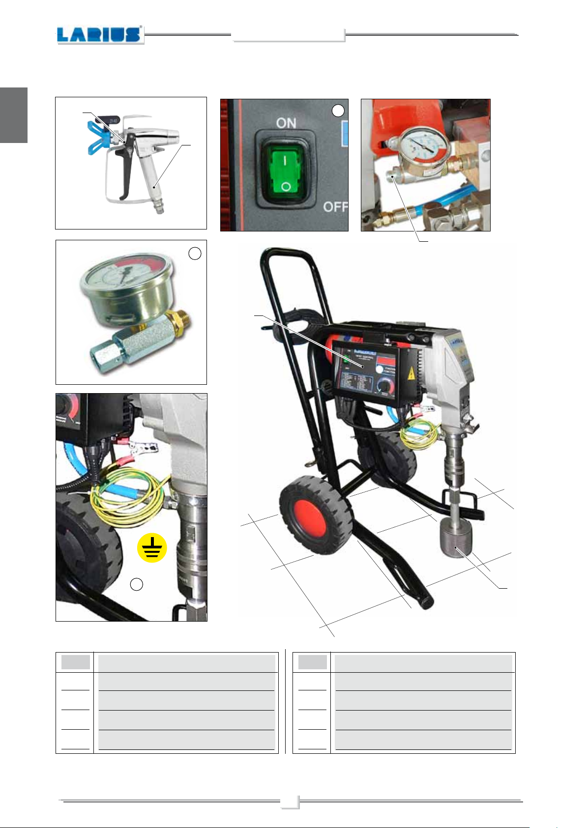
DESCRIPTION OF THE EQUIPMENT
C
7
English
1
2
6
5
3
7
6
3
5
POS. POS.
1
Electric motor
2
Pressure transmitter
3
Pumping group
4
High pressure flexible pipe of compen-
,
sation Ø3/8”
Description
5
6
7
4
Description
Recirculation tube
Recirculation - safety valve
Line filter (optional)
5
ZEUS
English
11
14
10
15
9
13
12
POS. POS.
8
Suction filter
9
Pressure gauge
10
Airless manual gun AT 300
11
Trigger safety clamp
Description
12
13
14
15
6
8
Description
Earth cable with clamp
Control equipment
ON/OFF switch
Flexible pipe connection
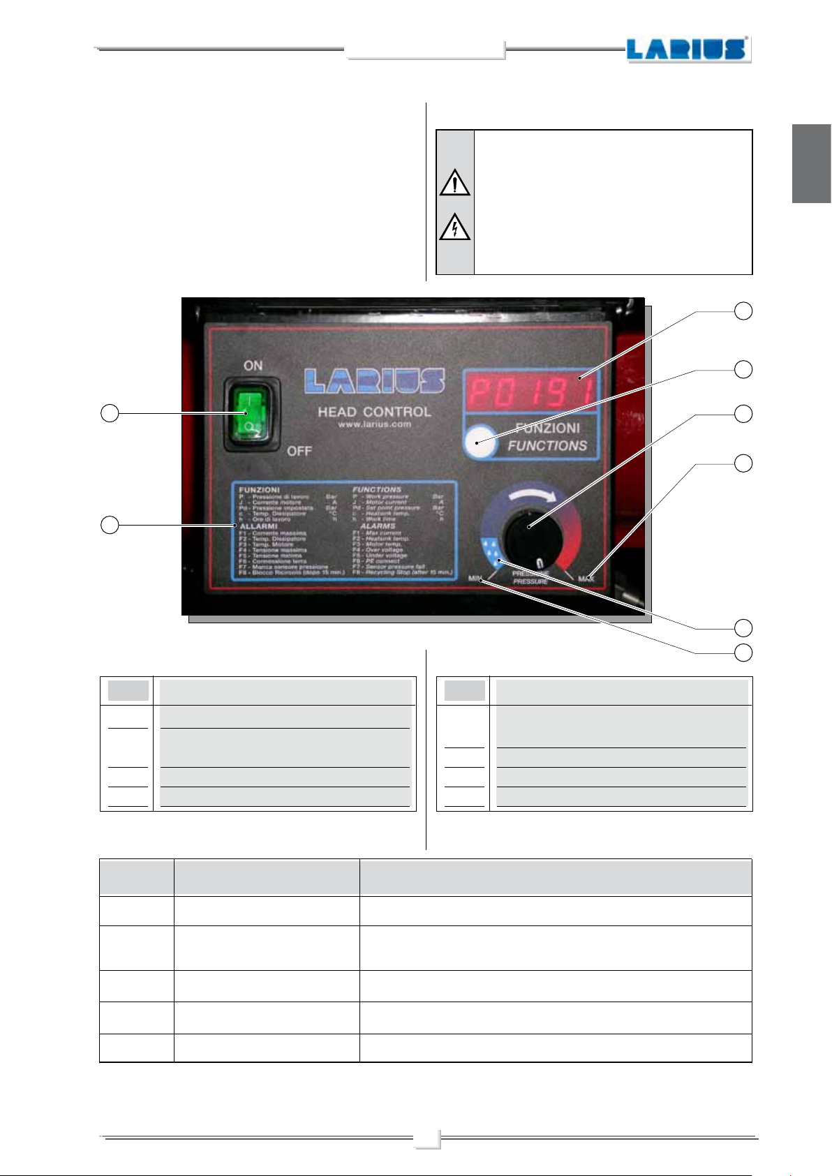
ALARM MESSAGES
ZEUS
When the product to be applied is finished the pump “sucks air”
and automatically switches to the minimum number of cycles.
The alarm messages function is described on the area sign (6).
Each time key (8) is pushed, the messages are displayed on the
screen (7).
1
6
When an alarm message has been indicated the
machine has to be switched off and on again using
switch (1).
Each time the machine is switched off, the condensers remain charged for about 5 minutes.
To avoid risk of shock, when removing the electrical
box wait until the condensers have discharged
altogether.
7
8
2
4
English
POS.
1
ON/OFF switch
2
Work pressure adjustment knob
,
,
3
Maximum pressure
4
Minimum pressure
FUNCTIONS TABLE
Function
symbol
P
J
Pd
c
Working pressure (bar)
Motor current (A)
Pressure setting (bar)
Dissipator temp. (°C)
Description
POS.
5
Material circulation and machine washing
,
position
6
Alarms
7
Message screen
8
Function keys
Description of functionType of function
Indicates the real time pressure used during the work cycle
Indicates the real time amperage on the equipment’s motor during the work cycle
Indicates the pressure set before the work cycle begins
Indicates the dissipator temperature (in degrees Centigrade) during the work cycle
Description
5
3
h
Working hours (h)
Indicates the total number of hours the equipment has worked
7

ALARM MESSAGE TABLE
ZEUS
English
Alarm symbol
F1
F2
F3
F4
F5
F6
F7
F8
Maximum current
Dissipator temp.
Motor temp.
Maximum voltage
Minimum voltage
Earth connection
Pressure sensor missing
Automatic switch-off during circulation
phase (15 minutes)
CauseType of alarm
The motor’s current absorption is too high
The dissipator temperature is too high
The motor temperature is too high
The voltage is too high
The voltage is too low
The earth connection is disconnected
or non-existent
The pressure sensor is damaged or
not fitted
The equipment is in cleaning mode
Solution
Check the mechanical and hydraulic
condition of the equipment. If necessary,
take action
Check that the dissipator surfaces are
clean and that the dissipator is properly
ventilated
Check that the motor’s heat dissipation
surfaces are clean. Check that cooling
ventilation is correct
Check the connection to the electrical line
and reinstate the correct nominal voltage
Check the connection to the electrical line
and reinstate the correct nominal voltage
Check the earth cable and, if necessary,
replace it. Make sure that the machine
is earthed
Replace it
Wait until the equipment has stopped
completely before using it for a new job
TRANSPORT AND UNPACKING
D
• The packed parts should be handled as indicated in the
symbols and markings on the outside of the packing.
• Before installing the equipment, ensure that the area to
be used is large enough for such purposes, is properly lit
and has a clean, smooth floor surface.
The user is responsible for the operations of
unloading and handling and should use the maximum care so as not to damage the individual
parts or injure anyone.
To perform the unloading operation, use only
qualified and trained personnel (truck and cra-
ne operators, etc.) and also suitable hoisting
equipment for the weight of the installation or
its parts. Follow carefully all the safety rules.
The personnel must be equipped with the necessary safety clothing.
• The manufacturer will not be responsible for the unloading
operations and transport to the workplace of the machine.
1
REMOVE THE SCREW
2
SCREW IN THE
SUPPLIED EYEBOLT
3
LIFT THE MACHINE
LIFTING POINTS
There are no precise lifting points for the machine in its entirety. In
order to determine the most appropriate lifting points, refer to the
geometric characteristics of the machine itself (proceed as shown).
8
ZEUS
• Check the packing is undamaged on receipt of the equipment. Unpack the machine and verify if there has been
any damage due to transportation.
In case of damage, call immediately LARIUS and the
Shipping Agent.
All the notices about possible damage or anomalies must
arrive timely within 8 days at least from the date of receipt
of the plant through Registered Letter to the Shipping
Agent and to LARIUS.
The disposal of packaging materials is a customer’s
competence and must be performed in accordance
with the regulations in force in the country where
the plant is installed and used
It is nevertheless sound practice to recycle packaging materials in an environment-friendly manner
as much as possible.
E
SAFETY RULES
• THE EMPLOYER SHALL TRAIN ITS EMPLOYEES ABOUT
ALL THOSE RISKS STEMMING FROM ACCIDENTS, ABOUT
THE USE OF SAFETY DEVICES FOR THEIR OWN SAFETY
AND ABOUT THE GENERAL RULES FOR ACCIDENT
PREVENTION IN COMPLIANCE WITH INTERNATIONAL
REGULATIONS AND WITH THE LAWS OF THE COUNTRY
WHERE THE PLANT IS USED.
• THE BEHAVIOUR OF THE EMPLOYEES SHALL STRICTLY
COMPLY WITH THE ACCIDENT PREVENTION AND ALSO
ENVIRONMENTAL REGULATIONS IN FORCE IN THE
COUNTRY WHERE THE PLANT IS INSTALLED AND USED.
.
• BEFORE USING THE TOOL, ENSURE THERE ARE NOT
DAMAGED PARTS AND THE MACHINE CAN WORK PROPERLY.
• ALWAYS FOLLOW THE INSTRUCTIONS ABOUT SAFETY
AND THE REGULATIONS IN FORCE.
• KEEP THOSE WHO ARE NOT RESPONSIBLE FOR THE
EQUIPMENT OUT OF THE WORK AREA.
• NEVER EXCEED THE MAXIMUM WORKING PRESSURE
INDICATED.
• NEVER POINT THE SPRAY GUN AT YOURSELVES OR
AT OTHER PEOPLE. THE CONTACT WITH THE CASTING
CAN CAUSE SERIOUS INJURIES. IN CASE OF INJURIES
CAUSED BY THE GUN CASTING, SEEK IMMEDIATE MEDICAL ADVICE SPECIFYING THE TYPE OF THE PRODUCT
INJECTED. NEVER UNDERVALUE A WOUND CAUSED BY
THE INJECTION OF A FLUID.
• ALWAYS DISCONNECT THE SUPPLY AND RELEASE THE
PRESSURE IN THE CIRCUIT BEFORE PERFORMING
ANY CHECK OR PART REPLACEMENT OF THE EQUIPMENT.
• NEVER MODIFY ANY PART IN THE EQUIPMENT. CHECK
REGULARLY THE COMPONENTS OF THE SYSTEM. REPLACE THE PARTS DAMAGED OR WORN.
• TIGHTEN AND CHECK ALL THE FITTINGS FOR CONNECTION BETWEEN PUMP, FLEXIBLE HOSE AND SPRAY GUN
BEFORE USING THE EQUIPMENT.
• ALWAYS USE THE FLEXIBLE HOSE SUPPLIED WITH STANDARD KIT. THE USE OF ANY ACCESSORIES OR TOOLING
OTHER THAN THOSE RECOMMENDED IN THIS MANUAL,
MAY CAUSE DAMAGE OR INJURE THE OPERATOR.
English
Read carefully and entirely the following instructions before using the product.
Please save these instructions in a safe place.
The unauthorised tampering/replacement of one
or more parts composing the machine, the use of
accessories, tools, expendable materials other than
those recommended by the manufacturer can be
a danger of accident.
The manufacturer will be relieved from tort and
criminal liability.
• KEEP YOUR WORK PLACE CLEAN AND TIDY. DISORDER
WHERE YOU ARE WORKING CREATES A POTENTIAL RISK
OF ACCIDENTS.
• ALWAYS KEEP PROPER BALANCE AVOIDING UNUSUAL
STANCE.
9
• THE FLUID CONTAINED IN THE FLEXIBLE HOSE CAN
BE VERY DANGEROUS. HANDLE THE FLEXIBLE HOSE
CAREFULLY. DO NOT PULL THE FLEXIBLE HOSE TO
MOVE THE EQUIPMENT. NEVER USE A DAMAGED OR A
REPAIRED FLEXIBLE HOSE.PER SPOSTARE L’APPARECCHIATURA. NON UTILIZZARE MAI UN TUBO FLESSIBILE
DANNEGGIATO O RIPARATO.
The high speed of travel of the product in the hose
can create static electricity through discharges
and sparks. It is suggested to earth the equipment.
The pump is earthed through the earth cable of
the supply.
The gun is earthed through the high pressure
flexible hose.
All the conductors near the work area must be
earthed.
ZEUS
English
• NEVER SPRAY OVER FLAMMABLE PRODUCTS OR SOLVENTS IN CLOSED PLACES.
• NEVER USE THE TOOLING IN PRESENCE OF POTENTIALLY EXPLOSIVE GAS.
Always check the product is compatible with the
materials composing the equipment (pump, spray
gun, flexible hose and accessories) with which it
can come into contact. Never use paints or solvents containing halogen hydrocarbons (as the
methylene chloride).
If these products come into contact with aluminium
parts can provoke dangerous chemical reactions
with risk of corrosion and explosion.
IF THE PRODUCT TO BE USED IS TOXIC, AVOID INHALATION AND CONTACT BY USING PROTECTION
GLOVES, GOGGLES AND PROPER FACE SHIELDS.
TAKE PROPER SAFETY MEASURES FOR THE
PROTECTION OF HEARING IN CASE OF WORK
NEAR THE PLANT.
• Take care when the pumping rod is moving.
Stop the machine whenever someone is within its vicinity.
• Repairs of the electrical equipment should only be carried
out by skilled personnel, otherwise considerable danger to
the user may result.
F
SETTING-UP
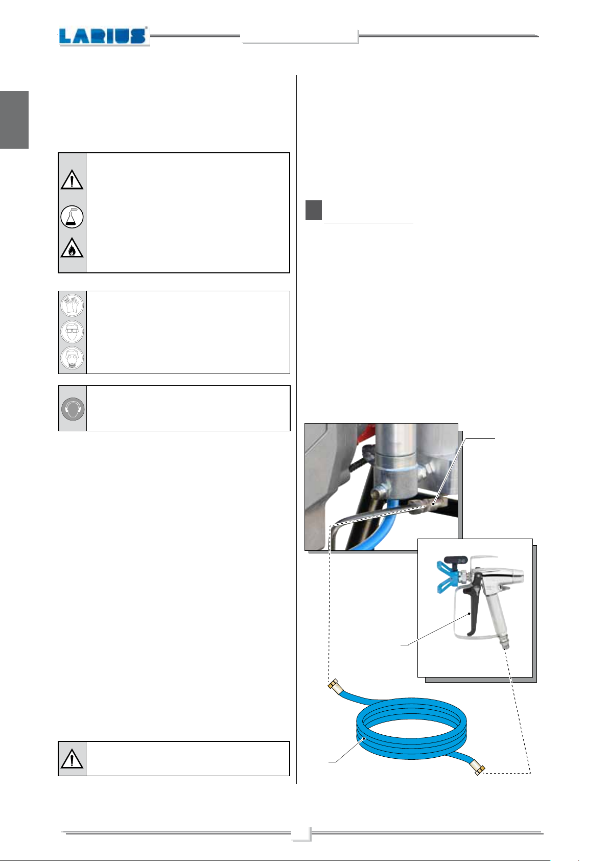
CONNECTION OF THE FLEXIBLE HOSE TO THE GUN
• Connect the high pressure flexible hose
(F2)
and to the gun
use of two wrenches is suggested)
NEVER use sealants on fittings’ threads
It is ADVISED to mount a high pressure manometer at the
pump outlet (see on page “Accessories”) to read the product
pressure
• It is recommended to use the hose provided with the standard
kit (ref.18036).
NEVER use a damaged or a repaired flexible hose.
.
(F3)
, ensuring to tighten the fittings (the
(F1)
to the pump
.
.
F2
Electrical safety precautions
• Check the switch is on the “OFF” position before connecting
the cable to the mains
• Never carry a plugged-in equipment.
• Disconnect the equipment before storing it and before performing any maintenance operation or replacing of accessories.
• Do not carry the equipment neither unplug it by pulling the
electric cable.
• Protect the cable from heat, oil and sharp edges.
• When the tool is used outdoors, use only an extension cable
suited for outdoor use and so marked.
Never attempt to tamper with the calibre of instruments.
.
F3
F1
10
ZEUS
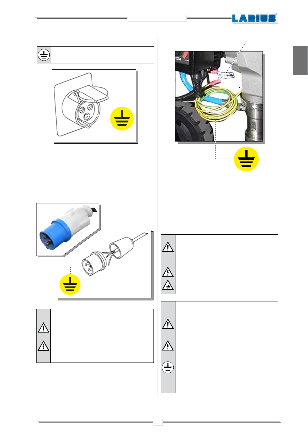
CHECK ON POWER SUPPLY
Make sure that the electrical system is earthed and
complies with regulations.
• Check the mains voltage corresponds to the equipment’s
rating.
• The supply cable is provided without plug.
Use a plug which guarantees the plant earthing.
Only a technician or a skilled person should perform the
connection of the plug to the electric cable.
F4
English
To avoid electric shock when disassembling or checking the electronic equipment, wait 5 minutes after having disconnected the
power supply cable, so that the electricity stored in the condensers
while working can be dissipated.
Should anyone use an extension cable between
the tooling and the socket, it must have the same
characteristics as the cable supplied (minimum
diameter of the wire 4 mm
th of 50 mt. Higher lengths and lower diameters
can provoke excessive voltage falls and also an
anomalous working of the equipment.
DRAGON equipment is fitted with an additional external earth
cable that is connected to the stem on the pump unit be means
of a specific clamp (F4), in order to protect the operator against
any risk of static or electric shock.
2
) with a maximum leng-
Also check the condition of the earth cable to avoid any risk of shock.
Before carrying out any checks on the machine
(maintenance, cleaning, or replacing parts) switch
off the machine and wait until it has stopped
altogether.
While checking stay away from electrical or moving
parts to avoid any risk of shock or crushing of hands.
WARNING :
• DO NOT modify the plug for the earth socket
in any way.
• ONLY use electrical connections that are
earthed.
• Make sure that any earth extension cords are
in good condition.
• ONLY use three-core extension cables.
• Avoid direct contact with the rain. Keep the
equipment in a dry place.
11
ZEUS
English
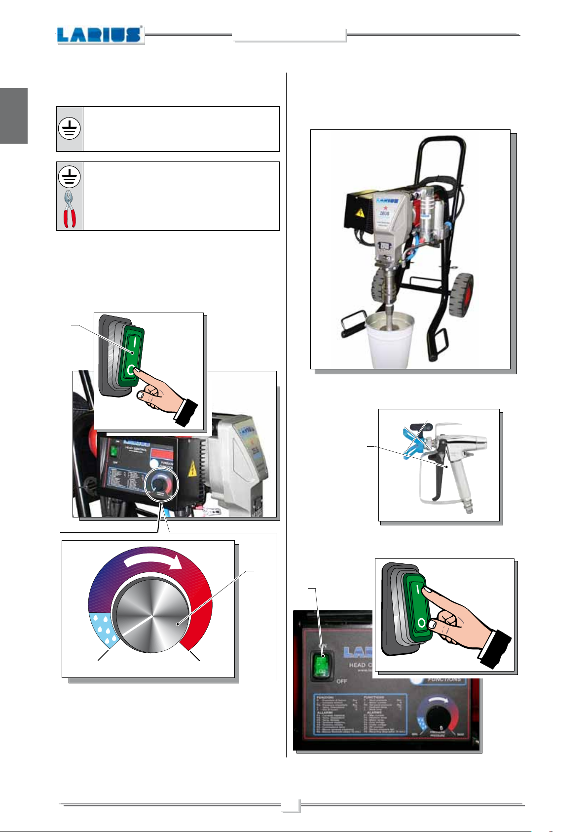
CONNECTION OF THE TOOLING TO THE POWER SUPPLY
Before connection up the power supply to the
equipment, make sure that the electrical system
is earthed and complies with regulations.
Make sure that the clamp (F4) provided is positioned correctly, in order to earth the pump unit in
the equipment properly.
• Check the switch (F5) is on the “OFF” (0) position before
connecting the cable to the mains.
• Place the pressure control knob (F6) on the “MIN” position
(turn counterclockwise).
F5
OFF
• Lift the suction unit and immerse it in the bucket that contains
the washing liquid.
• Connect the clamp to an earthing point.
MIN MAX
PRESSIONE
PRESSURE
F6
• Ensure the gun (F3) is without nozzle.
F3
• Press the switch (F5) of the equipment “ON” (I).
F5
ON
WASHING OF THE NEW EQUIPMENT
• The equipment has already been adjusted at our factory with
light mineral oil left inside the pumping group as protection.
Therefore, wash with diluent before sucking the product.
12

ZEUS
• Turn the pressure setting knob (F6) clockwise to the “CIRCULATION & WASHING” position (drop symbol).
Circulation
and washing
F6
F8
English
Absolutely avoid to spray solvents indoors. In
addition, it is recommended to keep away from
the pump in order to avoid the contact between
the solvent fumes and the electric motor.
MIN MAX
PRESSIONE
PRESSURE
Hold the spray gun against the edge of the metal
contained (F7).
• Point the spray gun into the collection container (F7) and hold
the trigger down (in order to expel the oil contained) until clean
liquid flows out.
Now, release the trigger.
Use a metal container (F7).
To avoid any risk of electric shock connect the
collection container to a surface that is earthed
(e.g. concrete) and not to surfaces that will insulate
the container from the earth.
• Remove the suction hose and remove the bucket of cleaning
liquid.
For disposing of the washing liquid, see the requirements laid down in the Standards in force in
the country in which the equipment is used and
act accordingly.
The Client is solely responsible for any irregular
action taken before, during, or after disposing of
washing liquid, or in interpreting and applying the
current Standards in this regard.
• Now the machine is ready.
When water-based paint has been used, in addition to washing
using the cleaning liquid, we recommend washing with soapy
water and then clean water.
PREPARING THE PRODUCT
MAKE SURE THE PRODUCT IS SUITABLE TO BE
USED WITH AN AIRLESS SPRAY GUN.
• Mix and filter the product before using it.
• Now point the spray gun (F8) into the container (F7) and press
the trigger to recover any cleaning liquid left.
• As the pump idles, press the “OFF” (0) switch (F5) to stop
the tooling.
When this is complete, release the trigger.
13
Make sure the product to be used is compatible
with the materials employed for manufacturing the
equipment (stainless steel and aluminium).
Because of that, please contact the supplier of the
.
product

ZEUS
English
Never use products containing halogen hydrocarbons (as methylene chloride). If these products come into contact with aluminium
parts of the equipment, can provoke dangerous chemical reactions
with risk of explosion.
REMOVE THE FILTER (F9) FOR DENSE PRODUCTS.
WORKING
G
START OF THE WORKING OPERATIONS
Make sure that the electrical system is earthed and
complies with regulations.
Make sure that the earth clamp is positioned
correctly to ensure a safe earth on the pump unit.
• Use the tooling after performing all the SETTING UP operations above described.
• Dip the suction pipe (G1) into the product tank.
F9
NO
G1
PRODUIT
14

• Open the recirculation - safety valve (G2).
Aperto
G2
ZEUS
English
G4
• Press the switch (G3) of the equipment “ON” (I).
G3
ON
Circulation
and washing
MIN MAX
• Make sure that the product circulates regularly from the
circulation hose (G5).
• Close the recirculation - safety valve (G2).
G5
• Turn the pressure setting knob (G4) clockwise to the “CIRCULATION & WASHING” position (drop symbol).
Chiuso
G2
• The machine continues to suck up product until it has filled the
hose as far as the spray gun, after which it will automatically
stop when the set pressure is reached.
15

ZEUS
English
SPRAY ADJUSTMENT
• Slowly turn clockwise the pressure control knob (G4) to reach
the pressure value in order to ensure a good atomization of
the product.
NEVER point the spray gun at yourselves or at
other people. The contact with the casting can
cause serious injuries.
In case of injuries caused by the gun casting, seek
immediate medical advice specifying the type of
the product injected.
Safety valve: when working at the maximum pressure available, releasing the gun trigger sudden
increases of pressure can occur. In this case, the
safety valve (G5) opens automatically eliminating
part of the product from the recirculating tube (G6).
Then it closes so as to go back to the first working
conditions.
The valve (G2) serves two purposes:
• Safety: It opens the passage at pressure peaks exceeding
280÷300 bar;
G4
• An irregular and marked spray on the sides indicates a low
working pressure. On the contrary, a too high pressure causes
a high fog (“overspray”) and waste of product.
• In order to avoid overthickness of paint, let the gun advance
sideways (right-left) when spraying.
• Regulation: It returns the working pressure to 230 bar and
levels out the hydraulic operating hysteresis.
G5
G2
H
CLEANING AT THE END
• Always paint with regular parallel bands coats.
• Keep a safety and constant distance between the gun and the
support to be painted and also keep yourselves perpendicular
to it.
OF THE WORK
CLEANING FOR SOLVENT-BASED PRODUCTS
Make sure that the electrical system is earthed and
complies with regulations.
16

ZEUS
• Reduce pressure to the minimum (turn counterclockwise the
pressure control knob (H1)).
• Press the switch (H2) “OFF (0)” placed on the box of the
electric motor, to stop the equipment.
H2
OFF
• Hold the spray gun trigger down.
English
• Open the recirculation - safety valve (H3) to release the
pressure in the circuit.
H3
Open
• Lift the suction hose and replace the bucket containing the
product with a bucket of cleaning liquid (make sure it is com-
patible with the product you are using).
• Unscrew the nozzle on the spray gun (remember to clean it
with cleaning liquid).
• Press the switch (H2) “ON” (I) of the equipment.
H2
ON
MIN MAX
PRESSIONE
PRESSURE
H1
17

ZEUS
English
• Turn the pressure setting knob (H1) clockwise to the “CIRCULATION & WASHING” position (drop symbol).
H1
• Close the recirculation - safety valve (H3).
H3
Closed
Chiuso
• Point the spray gun (H4) into the container (H5) used to
collect the cleaning liquid and hold the trigger down to expel
any product remaining, until clean liquid flows out.
Now, release the trigger.
Circulation
and washing
MIN MAX
PRESSIONE
PRESSURE
• Make sure that the product circulates through the circulation
hose.
Make sure that the machine sucks in clean washing
liquid. Allow the cleaning liquid to discharge into
another container and do not mix it with the cleaning
liquid still to be used.
We recommend circulating the cleaning liquid for
at least 15 minutes.
For disposing of the washing liquid, see the requirements laid down in the Standards in force in
the country in which the equipment is used and
act accordingly.
The Client is solely responsible for any irregular
action taken before, during, or after disposing of
washing liquid, or in interpreting and applying the
current Standards in this regard.
Hold the spray gun against the edge of the metal
contained (H5).
Use a metal container (H5).
To avoid any risk of electric shock connect the
collection container to a surface that is earthed
(e.g. concrete) and not to surfaces that will insulate
the container from the earth.
H4
H5
18

ZEUS
• Lift the suction hose and remove the bucket of cleaning liquid.
• Now point the spray gun (H4) into the container (H5) and
press the trigger to recover any cleaning liquid left.
H4
H5
• In case of long storage, we recommend you to suck and to
leave light mineral oil inside the pumping group and the flexible
hose.
Follow the washing procedure before using again
the equipment.
• Take the cleaning liquid and store it in suitable containers.
Make sure that the machine sucks in clean washing
liquid. Allow the cleaning liquid to discharge into
another container and do not mix it with the cleaning
liquid still to be used.
We recommend circulating the cleaning liquid for
at least 15 minutes.
English
• As the pump idles, press the “OFF” (0) switch (H2) to stop
the tooling.
H2
OFF
CLEANING FOR WATER-BASED PRODUCTS
Make sure that the electrical system is earthed and
complies with regulations.
• Reduce pressure to the minimum (turn counterclockwise the
pressure control knob (H1)).
H1
Circulation
and washing
MIN MAX
PRESSIONE
PRESSURE
19

ZEUS
English
• Press the switch (H2) “OFF (0)” placed on the box of the
electric motor, to stop the equipment.
H2
OFF
• Lift the suction hose and replace the bucket of product with
an empty bucket (H6).
• Connect a rubber hose (H7) to a water tap (H8) and fill the
bucket (H6).
• Position an empty bucket to collect the water (H9) under the
circulation hose (H10).
H8
H7
H10
• Hold the spray gun trigger down.
• Open the circulation - safety valve (H3) to discharge the
pressure in the circuit.
H3
Open
H6
H9
20

ZEUS
• Press the switch (H2) su ON (I) and turn a little the pressure
control knob (H1) clockwise so as the machine works till
the motor starts.
H2
ON
• Run the pump’s washing cycle until clean water flows out of
the circulation hose (H10).
English
• Close the recirculation - safety valve (H3).
H3
Closed
Chiuso
• Remove the suction hose and the rubber hose (H7) and take
away the bucket of water (H6).
H1
• Now point the spray gun (H4) into the container (H5) and
press the trigger to recover any cleaning liquid left.
H4
H5
• As the pump idles, press the “OFF” (0) switch (H2) to stop
the tooling.
21

English
H2
OFF
ZEUS
• Use the lubricant (I1) provided (ref. 16325) to make it easier
to slide the piston inside the seal pack and to substitute the
air with oil.
At the start of each working day check that the
ring nut is full of hydraulic oil (Ref. 16325). This oil
makes it easier for the piston to slide and prevents
any material that escapes via the seal gasket drying
when the equipment is stopped.
Oil ring
• In case of long storage, we recommend you to suck and to
leave light mineral oil inside the pumping group and the flexible
hose.
Follow the washing procedure before using again
the equipment.
If the equipment is to be stopped for a lengthy period
of time, carry out the cleaning operations described
previously, according to the type of product used.
In case of short stoppages, suck in some water
and leave the pump unit in the bucket (H6) for a
few minutes.
ROUTINE MAINTENANCE
I
CHECK ON THE PACKING NUT
The gaskets do not need adjusting. The ring nut is only used to
fit and remove gaskets and for topping up the oil.
Always disconnect the electrical supply and
discharge the pressure in the pump unit (open
the discharge valve) before carrying out any
maintenance.
Wait 30 seconds before proceeding with maintenance operations to allow any residual electricity
to be discharged.
I1
Rif. 16325
• The ring nut (I2) must be tightened all the way.
Every 100 working hours, with the pressure at 0 bar, check
that it is tightened all the way.
• The supplied pin (I3 – ref. 20144) also serves the purpose of
closing and opening the pump unit’s locking ring-nut (I4). This
ring nut must always be closed in order to act as a locking
counter-nut.
I2
Ref. 20144
Closing/opening
pin
I3
22
I4

ZEUS
CHECKING THE HEAT EXCHANGE RADIATOR
Always keep the heat exchange radiator (I5) on the electronic
control box clean, in order to guarantee correct heat exchange
with the ambient air.
We suggest cleaning using a jet of compressed air.
I5
English
PRESSURE SWITCH SEAL CHECK
Check that no material is escaping from the safety hole (I6) at the
bottom of the protective container.
If necessary, replace the O-Ring for the pressure sensor (I7).
I7
I6
23

ZEUS
J PROBLEMS AND SOLUTIONS
English
Problem
• The equipment does not start
• The equipment does not suck the
product
Cause
• Lack of voltage;
• Considerable drops in mains voltage;
• On/Off switch disconnected;
• Breakdown of pressure transmitter;
•
Breakdown of motor electric control box;
• The line of material coming out of the
pump is already under pressure;
• The product is solidified inside the
pump;
• Suction filter clogged;
• Suction ilter too fine;
• The equipment sucks air;
Solution
• Check the correct connection to the
power supply;
• Check the extension cable;
• Ensure the On/Off switch is on the
“on” position and turn clockwise the
pressure control knob;
• Verify and replace it, if necessary;
• Verify and replace it, if necessary;
• Open the drain valve to release
pressure in the circuit;
• Open the drain valve to release
pressure in the circuit and stop the
machine. Disassemble the pumping
group and the pressure transmitter
and clean;
• Clean or replace it;
• Replace it with a larger-mesh filter
(with very dense products, remove
the filter);
• Check the suction pipe;
• The equipment sucks but does not
reach the pressure desired
• When pressing the trigger, the
pressure lowers considerably
• The pressure is normal but the
product is not atomized
• The atomization is imperfect
•
When releasing the trigger of the
gun, the equipment does not stop
(the motor runs slowly and the
piston rod keeps on going up and
down)
• Material escaping from the cap
• Lack of product;
• The equipment sucks air;
• The drain valve is open;
• The gaskets of the pumping group are
worn;
• Suction or delivery valve dirty;
• Nozzle too big or worn;
• The product is too dense;
• The filter of the gun-butt is too fine;
• The nozzle is partially clogged;
• The product is too dense;
• The filter of the gun-butt is too fine;
• The nozzle is worn;
• The gaskets of the pumping group are
worn;
• Suction or delivery valve dirty;
• Drain valve defective;
• Material leaking from the O-Ring.
• Add the product;
• Check the suction pipe;
• Close the drain valve;
• Replace the gaskets;
• Disassemble the pumping group;
• Replace it with a smaller one;
• Dilute the product, if possible;
• Replace it with a larger-mesh filter;
• Clean or replace it;
• Dilute the product, if possible;
• Replace it with a larger-mesh filter;
• Replace it;
• Replace the gaskets;
• Disassemble the pumping group and
clean;
• Verify and replace it, if necessary;
• Replace the O-Ring.
Always close the air compressed supply and unload the plant pressure before performing any check or replacement of pump parts (see "correct procedure of decompression").
24

ZEUS
K
CORRECT PROCEDURE OF DECOMPRESSION
English
Make sure that the electrical system is earthed and
complies with regulations.
• Zero the pressure regulator knob.
• Move the switch (K1) to the OFF (0) position to stop the
equipment.
K4
Clamp inserted
Clamp released
• Open the circulation - safety valve (K2) to discharge the
residual pressure, always turning it anticlockwise.
• Point the gun at the tank (K3) of the product and press the
trigger to release pressure. At the end of the operation, insert
the gun clamp (K4).
K1
OFF
K2
K3
WARNING :
If the equipment is still under pressure after performing the operations above described because of the nozzle or
the flexible hose clogged, proceed as follows:
• Loosen very slowly the gun nozzle.
• Release the clamp.
• Point the gun at the container of the product and press the trigger to release pressure.
• Loosen very slowly the fitting of connection from the flexible hose to the gun
• Clean or replace the flexible hose and the nozzle.
.
25

ZEUS
L
REPLACEMENT OF THE PUMPING GROUP’S GASKETS
English
Each time you use the machine, check for material leaking from
the top of the ring nut.
If any material leaks out when the pump is working at the set
pressure, proceed as follows:
• Carry out this operation after cleaning the tooling.
Always disconnect the power supply and release
pressure before going on with the operations
(follow the “correct procedure of decompression).
The gaskets are self-adjusting. If a leak occurs
they must be replaced.
• Disconnect the product feed hose (L1) from the pump unit
by unscrewing the nut (L2).
• Unscrew the fixing ring nut (L3) using the relevant closing pin
(Ref. 20144).
• Turn the motor (L6) with a screwdriver (L5) until the piston
rod has moved to the lowest point of its stroke.
L5
L6
• Screw the appropriate supplied tool (L7 – ref- 20213) into the
threaded hole on the holding pin (L8).
L8
Ref. 20144
• Release the plastic cover (L4).
L4
L3
L2
L1
Ref. 20213
L7
• Remove the pin (L8) from its seating.
26
L8

ZEUS
• Unscrew the pump unit (L9) from the frontal flange. (L10).
L10
Lower seal
• Remove the piston stem (L11) and remove the pump unit
sleeve (L12);
L9
L11
English
PIT STOP MAINTENANCE
Replacement of upper and lower gaskets 20 minutes.
• Lock the pump unit into a vice and unscrew it with a 50mm
wrench;
•
Release the pump unit from the body of the suction valve;
Countersunk
side
L12
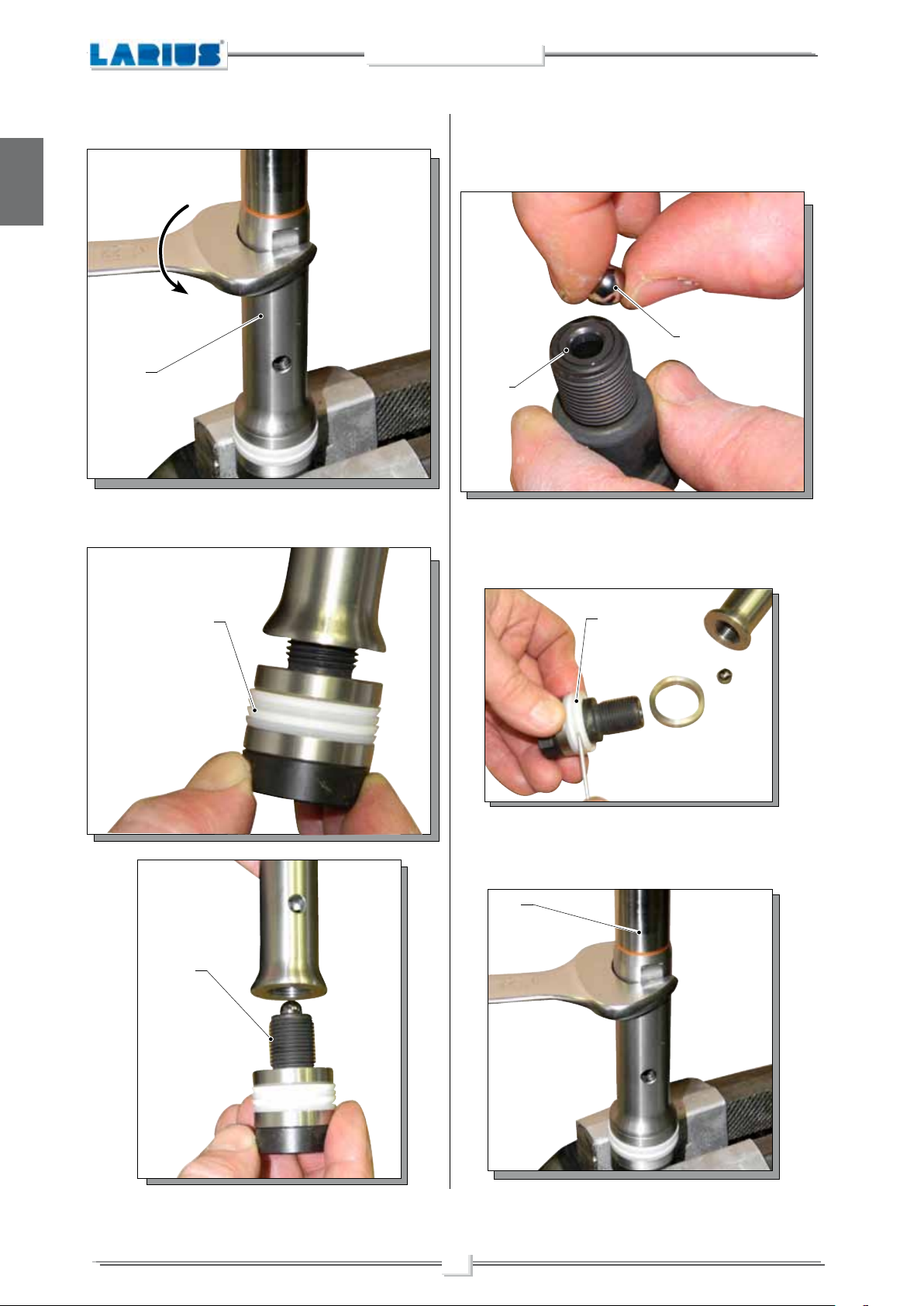
• Grip the stem valve (L13) in a vice;
L13
27
ZEUS
English
• Use a size 24 spanner to unscrew the lower stem (L14);
L14
• Use a screwdriver to remove the two open-ring guide bands
(L15) and replace them;
• Unscrew the stem valve (L16) altogether, check the surface
of the ball seating (L17) that comes into contact with the ball
(L18).
If worn, replace them;
L18
L17
• Use a screwdriver to remove the O-Ring (L19) and replace
it making sure it is aligned correctly (as illustrated);
L16
L15
L19
• Screw the valve stem (L16) (Ref. 20139) on again and tighten
fully, gripping the valve in a vice. To tighten, use a 22 mm
spanner; the use of a thread paste is recommended;
L16
28

ZEUS
Upper seal
• Remove the ring nut (L20);
• Remove the ring (L21) ;
L23
English
L20
• Using a screwdriver, extract the second band (L24) located
below the seal (L23) and insert a new band in the same
position;
L24
L21
• Remove the guide band (L21) with a screwdriver and replace
it with a new one;
L22
Channel
extraction
guide ring
The positioning of the seal (L23) equires special
care during assembly.
• Assist insertion by applying leverage to the outside of the ring
(L23), pushing from the outside inwards and helping the ring
to lodge in the seating, while being careful not to damage the
ring’s contact surfaces.
Lubricate with grease before fitting.
L23
• Remove the seal (L23) with a screwdriver;
29

English
Only if damaged
• Remove the OR (L25-L26-L28) from the body of the foot valve
(L29) and from the ball seat holder (L27) and, if necessary,
replace them.
Reassemble the components in their proper order (as indicated
in the diagram);
L25
L26
L27
ZEUS
• Screw the locking ring nut (L20) back onto the body of the
pump unit until it makes contact, then loosen it by one turn;
L20
L28
To facilitate fitting the O-ring (L28) it is advisable
to warm it slightly with a blast of hot air.
• Check the integrity of the surface area of the sphere in contact
with the ball (L17). If worn replace the complete detail.
• Remove the sleeve/cylinder seal (L30) and replace it with a
new one;
L18
L17
The ball seating (L17) is countersunk on one side,
where the ball (L18) must sit.
L29
30

• Check the wear status of the surfaces inside the jacket.
Replace it if necessary;
• Grease the sleeve (L31) using a paintbrush;
L30
ZEUS
English
L33
L32
Countersink on the jacket
• Insert the sleeve (L31) into the lower pump unit (L32);
L31
L30
Insert the complete piston stem (L33) after greasing
the gaskets (L34);
LUBRICATE
• Screw on the complete foot valve (L29) with the sleeve assembly (L30);
In order to guarantee a proper seal, tighten the foot
valve (L29) fully, using a 50 mm spanner.
L29
31
L28

ZEUS
English
• When refitting the pump unit on the machine, the stem must
be at its highest point possible.
• Insert the stem into the connecting rod and insert the fixing
pin (L8).
L8
• Tighten the pump casing all the way and, if the delivery pipe
is not correctly aligned, unscrew the pump casing until the
connection is in the correct position before tightening by using
the ring nut (N35) and the pin (N36) supplied (Ref. 20144).
• Lubricate the upper crown (L38) using oil (L39) (Ref. 16325);
Oil ring
L38
L39
Ref. 16325
• Refit the inspection barrier (L40);
L40
Closing/opening
L35
• Close the seal ring nut (L37) all the way.
L37
Ref. 20144
pin
L36
• To assemble all the parts in the correct sequence, see the
exploded diagram on page 36.
32

SPARE PARTS
SPARE PARTS
Electric motor
O
R
Page 43
Electrical control - exploded view
O
P
Page 40
Complete electro-mechanical Unit
O
M
Page 34
Basic hydraulic block
O
N
ref. 30400
Page 36
English
O
Q
O
O
Carriage
page 42
Complete
standard
pumping
element
Page 38
Complete short
O
O
pumping
element
Page 38

English
ZEUS
COMPLETE ELECTRO-MECHANICAL UNIT
OM
9
3
4
41
trolley
Mounted on a
36
32
Material supplied
(not installed on the machine)
38
42
5A
5B
5A
10
38
1
13
7A
7B
7A
1A
2
7
5
6
8
15
14
171618
17
23
30
34
23
35
19
44
Earth cable
25
ref.5010
12
33
26
22
20
21
43
ref.20213
Plug extractor
11
31
6
5
40
45
27
37
8
7
39
24
28
4
29
34

ZEUS
Pos.
-
.
-
.
1
.
1A
2
3
4
5
5A
5B
6
Code Description Q.ty
35144
.
35149.
.
35145
35146
-
30201
30669
34009
20250
20251
20252
20253
Complete electromechanical unit
model 220V 50Hz
Complete electromechanical unit
model 110V 60Hz
Electric motor 220V 50Hz
Electric motor 110V 60Hz
ACM Shaft motor
Flange motor
Screw M8X40
Washer Ø 8
INA Thrust bearing complete
Fifth wheel
Cage
INA Roller bearing
1
1
1
1
1
1
4
6
2
4
2
2
Pos.
19
20
.
21
22
.
23
24
25
26
27
28
29
30
31
32
Code Description Q.ty
30261
30262
30263
30210
20264
30665
30266
5378
30211
30212
69011
30202
35141
30270
INA Roller bearing
Complete connecting rod
Positioning spring
Pump unit pivot
Centring pin Ø 6X20
Guide bushing
Scraper
Screw M4X10
Inspection hatch
Tin plate door
Screw M8X20
Reduction unit cover
Cover assembly
Eyebolt M16
1
1
1
1
2
1
1
2
1
1
2
1
1
1
English
7
7A
7B
8
9
10
11
12
13
14
15
16
17
18
30254
30255
30256
30257
30271
20205
20204
20258
20207
30206
30259
30272
30208
30209
Thrust
Fifth wheel
Cage
INA Roller bearing
Screw M8X90
Toothed wheel court
Court toothed
Toothed driving assembly
Wheel
Shaft
Cam assembly
Spina distanziale Ø 6X10
Guide bushing
Connecting rod
2
35143
34
4
34020
35
2
21688
36
2
20245
37
2
30245
38
1
96211
39
1
30274
40
1
35152
41
1
18478
42
1
30666
43
1
30225
44
1
20278
45
2
1
Fixing ring
Front sticker
Rivet Ø 2 mm
Plug
Screw M4X10
Screw M8X60
Screw M6X10
Warning label
Plug
Threaded spacer
Tightening ring
Fixing ring
Pin cil.
1
1
6
1
1
4
1
1
1
1
1
1
1
30214
33
35

English
ZEUS
N
BASIC HYDRAULIC BLOCK REF. 35160
WARNING: Always indicate code and quantity for each part required.
41
529
57
55
56
51
49
54
4
50
48
Short
draft line
Ref.35161
14
13
Assembly
15
16
8
17
18
31
20
19
32
21
47
53
3
35
45
46
44
43
42
7
6
1
11
33
70
8
34
9
52
10
22
12
2
24
23
27
64
26
61
34
63
25
37
62
28
61
38
34
36
39
38
40
58
59
9
30
60
58
65
draft line
Standard
Assembly
66
67
68
69
Ref. 35164
36

ZEUS
Pos.
-
1
2
3,
4
5
6
7
8
9
10
11
12
13
14
Code Description Q.ty
35160
30401
5756
20457
20402
20450
34009
6151
33010
33006
95114
30451
32005
20436
96255
Hydraulic block complete
Block base
Self-locking nut
Digital pressure switch
Protection
Cable fastener
Washer Ø 8
Screw M8X50
Sealing washer
Nipple M16X1,5
Washer Ø12
Screw M12X55
Washer Ø6
Screw M6X60
Union 0 M-M Gc 1/2”
1
2
1
1
1
2
2
1
1
2
2
3
3
1
Pos.
-
36
37
38
39
40
41
42
43
44
45
46
47
48
49
50
Code Description Q.ty
20455
37261
18511
18509
18211
37440
8402
37447
301013
37284
37446
37281
37449
8026/1
37444
Discharge tube assembly
Rubber holder
3/8 Bushing tube
Pipe compensator 3/8
Union o tuboeGj 3/8
Recirculation valve compl.
OR 2087
Valve casing
OR 2025
O-Ring
Complete rod
Spring
Bush
Dowel M5X6
Positioning peg
1
1
2
1M
1
1
1
1
1
1
1
1
1
1
1
English
15
16.
17
18
19
20
21
22
23
24
25
26
27
28
29
30
20451
30430
3387
20557
18350
18351
18352
8071
96202
96201
37452
37454
53011
147
30439
30469
Elbow M-F Gc 1/2” - Gj 1/2”
Reduction F-F 1/2-3/8 cylindrical
Nipple M-M 3/8” - M20X2
Recirculation pipe compl.
Bell Splash
Bell
Scatter pin
1/2” sealing washer
Sieve spring
Filter tank
Ball seat
Gasket
Manometer
Complete pressure gauge
Warning stickers
Filter assembly
1
51
1
52
1
53
1
54
1
55
1
56
1
57
1
58
1
59
1
60
1
61
1
62
1
63
1
64
1
65
1
66
16405
11056
37283
7154
37441
4050
37445
96205
96206
96204
37453
96203
96207
95218
5656
16131
Handle
Ø 2,5 mm rivet
Sealing washer
Ball seat
Valve casing
Ø6 ball
Rod stem
Dowel Gc 1/4X10
Nipple M-M 1/4” - M16X1.5
Base filter
Union
OR
Sieve holder
Filter sieve
Reduction Gc 1/2 M -Gj 1/4 F
Union Gj 1/4 M-M14X1M
1
1
1
1
1
1
1
2
1
1
2
1
1
1
1
1
31
32
33
34
35
20556
37216
34109
33007
20421
Induction pipe
Drum filter
Union M-M Gc-Gj 3/8
Washer 22X16.2 SP. 15
O-Ring
1
67
1
68
1
69
3
70
1
35166
20460
35168
35158
Standard recirculation coupling
Blocking coupling
Recirculation tube
Label Technical Data
1
1
1
1
37

English
ZEUS
O COMPLETE PUMP UNIT
WARNING: Always indicate code and quantity for each part required.
27
CORRECT
FITTING
LIP
38
21
26
25
40
24
23
22
20
19
ZEUS
Tightening pin
Ref.20144
Complete intake tube
and recirculation
Ref. 35161
39
9
31
32
33
37
42
11
10
CORRECT
FITTING
18
17
16
41
15
14
13
12
8
7
6
5
30
29
28
35
36
4
3
2
34
1
38

ZEUS
Pos.
-
-
-
-
-
-
-
-
-
-
1
2
3
4
5
Code Description Q.ty Code Description Q.ty
35100
35102
35150
35155
35110
35111
35112
35113
35114
35161
37216
35118
37229
35115
35116
Zeus standard 220 V
Zeus short 220 V
Zeus standard 110 V
Zeus short 110 V
Complete standard pump unit
Complete pumping with suction hose
Foot valve seal kit
Complete seal kit
Jacket+piston kit
Suction hose kit + recirculation
Suction filter
Hard suction hose
Connection
Foot valve
Assembled at Ball
Pos.
37180
17
-
35131
18
-
35133
19
-
35134
20
-
95230/1
21
-
35135
22
-
30142
23
-
30139
24
-
30138
25
-
30114
26
-
30113
27
1
35162
28
1
35119
29
1
96836/2
30
1
98374
31
1
O-Ring
Upper stem
Sleeve
Seal
Adapter 3/8 AP M-M
Pump unit casing
67806-X0220-56Z
EAR 148856-02
67806-X0220-A22Z
Tightening ring nut
Stuffing nut
OR 3087
Accommodation ball seat
See ball
Elbow joint F-F Gj 3 / 4
1
1
1
1
1
1
1
1
1
1
1
1
1
1
1
English
6
7
8
9
10
11
12
13
14
15
16
35163
35138
35121
35122
35124
7062
35125
7071
35151
35154
35157
35129
Ball Ø 3/4”
Ball guide
OR 3156
OR 3206
Valve stem
See ball
Valve stem comp.
Ball Ø 9
Ring female lower
Polyethylene gasket
PTFE gasket
Lower stem
1
96099
33
1
35139
34
1
35117
35
1
35123
36
1
35132
37
1
35136
38
1
35137
39
1
30122
40
1
35142
41
2
35159
42
2
1
Suction fitting Jas M-M 3 / 4 - M36x2
Seal sleeve
Assembly float rigid
Assembly the valve seat F
Assembly the group see fund
Assembly the stem
Assembly cylinder
Suction hose Assembly kit
Ring seal top awards
Ring male
Pack lower packing
lower
1
1
1
1
1
98376
32
39

English
ZEUS
OP
ELECTRICAL CONTROL - EXPLODED VIEW
WARNING: Always indicate code and quantity for each part required.
4
Complete
220V - 50Hz
110V - 60Hz
Ref.20350/110
box Ref.20350
12
2
7
13
1
14
6
3
6
5
8
40
9
11
12

ZEUS
Pos.
-
-
1
2
3
4
5
6
Code Description Q.ty Code Description Q.ty
Electronic box A C.
30350
30357
5933
20355
20354
96028
20365
18483
- Model 220V - 50Hz
- Model 110V - 60Hz
Switch
Panel
Electronic box
Screw
Electronic board
Short rubber seal
Pos.
18493
7
20352
8
-
8011
9
-
10
1
11
1
12
1
13
6
14
1
2
34009
34008
20340
20349
30280
Tightening plate
Dissipator
Anti-vibration washers
Washer
Screw
Transparent sheet
Knob
Technical data label
English
1
1
3
3
3
1
1
1
41

ZEUS
O
CARRIAGE
Q
WARNING: Always indicate code and quantity for each part required.
English
Carriage in compact position
Carriage in extended position
1
2
3
4
Pos.
-
1
2
3
4
5
7
6
8
Code Description Q.ty Code Description Q.ty
30300
30301
95159
18914
30302
Complete carriage
Carrying handle
Pipe cap
Bushing
Carriage
Pos.
18902
5
-
20305
6
1
37238
7
2
30304
8
2
1
Split pin
Wheel stop washer
Wheel Ø260 mm
Pipe cap
2
2
2
2
42

ZEUS
ELECTRIC MOTOR
R
DISCONNECT THE POWER SUPPLY BEFORE CHECKING OR REPLACING THE BRUSHES.
• Periodically check on the wear of the pinion (at least every
1000 working hours).
• Periodically check the perfect connection among all the
electrical components (at least every 200 working hours).
• The length of the brush contact must be higher than 9 mm
to guarantee a good working of the rotary group.
English
Code
20280
20281
20282
24 mm*
*Length of new brush **Minimum length of the brush
Brush 220V 50Hz
Brush 110V 60Hz
Brush holder plug
Replace
Description
9 mm**
Q.ty
4
4
4
43

English
ZEUS
ACCESSORIES
S
WARNING: Always indicate code and quantity for each part required.
Art. 11000: AT 300 M16x1,5
Art. 11090: AT 300 1/4”
PISTON GUNSTOCK FILTERS
Code 11039: Green (30M) - Code 11038: White (60M)
Code 11037: Yellow (100M) - Code 11019: Red (200M)
HIGH PRESSURE HOSE 3/8" - M16x1,5 max pressure 425 bar
Code
18063: 7,5 mt
Code
18064: 10 mt
Code
18065: 15 mt
ANTIPULSATIONS 1/4" - M16x1,5 max pressure 250 bar
Code
35013: 5 mt
Code
35014: 7,5 mt
Code
35017: 10 mt
Code
18026: 15 mt
ANTISTATIC HOSE 3/16" - M16x1,5 max pressure 210 bar
Code
6164: 5 mt
Code
55050: 7,5 mt
Code
35018: 10 mt
Code
18510: COMPENSATION HOSE Ø3/8” Lenght 15mt
44

SUPER FAST-CLEAN
ZEUS
SUPER FAST-CLEAN TIP
SFC07-20
SFC07-40
SFC09-20
SFC09-40
SFC11-20
SFC11-40
SFC13-20
SFC13-40
SFC13-60
SFC15-20
SFC15-40
SFC15-60
SFC17-20
SFC17-40
SFC17-60
SFC19-20
SFC19-40
Nozzles code
SFC19-60
SFC21-20
SFC21-40
SFC21-60
SFC23-20
SFC23-40
SFC23-60
SFC25-20
SFC25-40
SFC25-60
SFC27-20
SFC27-40
SFC27-60
SFC27-80
SFC29-20
SFC29-40
SFC29-60
SFC29-80
SFC31-40
SFC31-60
SFC31-80
SFC33-40
SFC33-60
SFC33-80
SFC39-40
SFC39-60
SFC39-80
SFC43-40
SFC43-60
SFC43-80
SFC51-40
SFC51-60
SFC51-80
English
Code 18280: GASKET
Code
147: HIGH PRESSURE GAUGE M16X1,5
Code
150: HIGH PRESSURE GAUGE GJ 1/4”
Code 18270: SUPER FAST-CLEAN base UE 11/16x16
Code
10156: SWIVEL CONNECTION FOR PLA 1/4"
Code
10159: SWIVEL CONNECTION FOR PLA M16x1,5
Code 35185: PUMPING UNIT COMPLETE REPAIRING KIT
45

English
ZEUS
GUN EXTENSION
Art. 153: cm 30 -Art. 153: cm 40
Art. 155: cm 60 - Art. 158: cm 80 - Art. 156: cm 100
PLA
Code K11446:
Code K11445:
Code K11441:
Code K11440:
Code K11436:
Code K11435:
PLA 450 bar cm 240 1/4” + base SFC
PLA 450 bar cm 240 16 x 1,5 + base SFC
PLA 450 bar cm 180 1/4” + base SFC
PLA 450 bar cm 180 16 x 1,5 + base SFC
PLA 450 bar cm 130 1/4” + base SFC
PLA 450 bar cm 130 16 x 1,5 + base SFC
Art. 16780: TELESCOPIC PAINT ROLLER
complete with:
n. 1 Roller with extra-long fiber
n. 1 Roller with long fiber
n. 1 Roller with medium fiber
Flexible hose mt. 2 3/16 " M16x1,5
Code
217550: MX 850 - Art. 217560: MX 1000 -
MX 850
MX 1100
MX 1100 ER
Code
217570: MX 1100 ER
46

L’innovazione.
PAINT SPRAYING EQUIPMENT
Quella vera.
English

ELECTRIC PISTON PUMP
NEW EXCALIBUR top finish Rif. 18783
NEW EXCALIBUR on carriage Rif. 18776
DRAGON Rif. 30184
JOLLY Rif. 56501
THOR 220V/50Hz long pump unit Rif. 20705
THOR 220V/50Hz short pump unit Rif. 20700
MANUFACTURER:
23801 CALOLZIOCORTE - LECCO - ITALY - Via Antonio Stoppani, 21
Tel . (39) 0341/62.11.52 - Fax (39) 0341/62.12.43
E-mail: larius@larius.com - Internet http://www.larius.com
DIRECT LINE
CUSTOMERS TECHNICAL SERVICE
Tel. (39) 0341/621256
Fax (39) 0341/621234
 Loading...