

ENGLISH
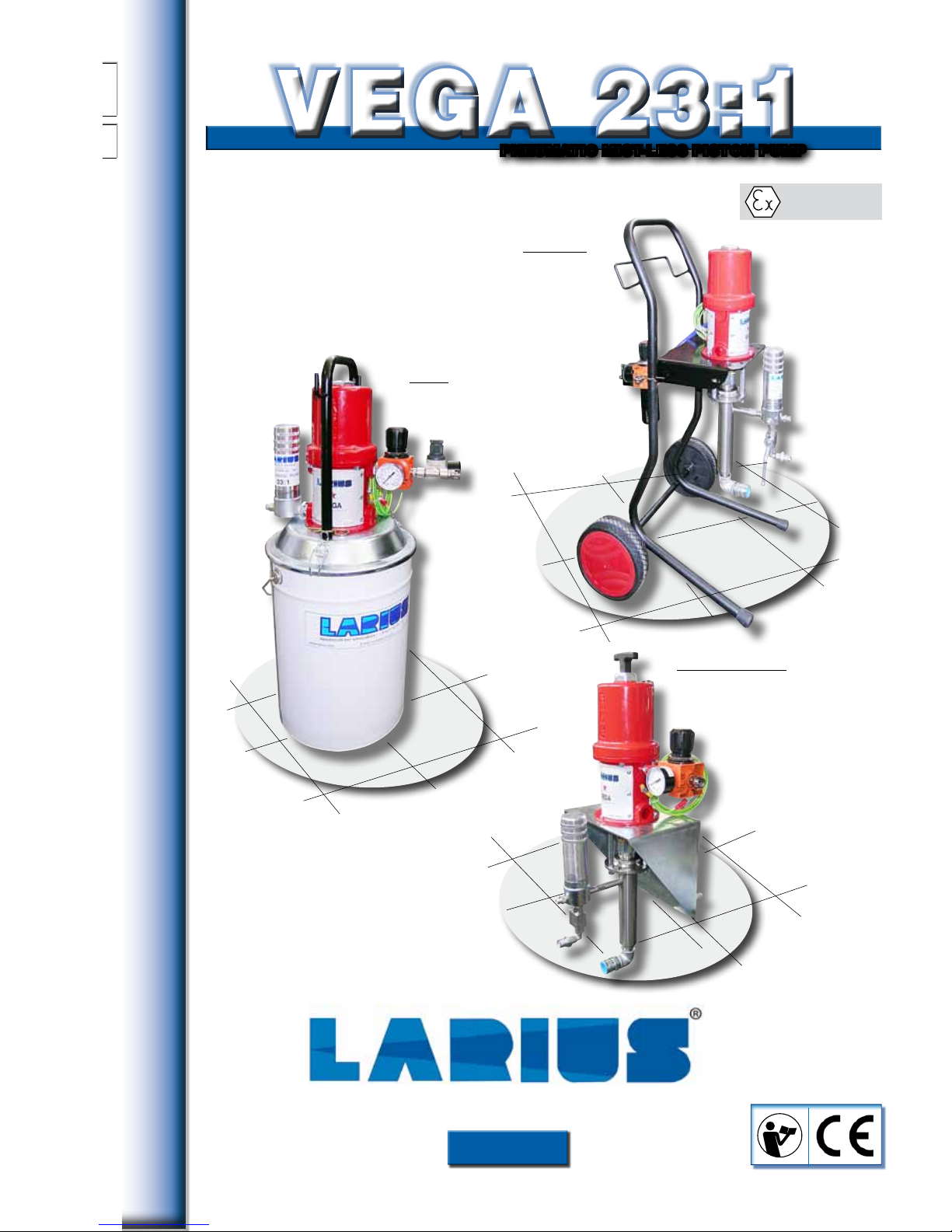
VEGA 23:1VEGA 23:1
PNEUMATIC MIST-LESS PISTON PUMP
II 2 G c IIB T4
A t e x C e r t i f i e d
WALL BRACKET
Version
Version
on TANK
TROLLEY
Version
OPERATING AND
MAINTENANCE INSTRUCTION
OPERATING AND
MAINTENANCE INSTRUCTION
Ed.
003
10 - 11
P A I N T S P R A Y I N G E Q U I P M E N T

WE RECOMMEND THE USE OF THIS EQUIPMENT ONLY BY PROFESSIONAL OPERATORS.
USE THIS MACHINE FOR PURPOSES SPECIFICALLY MENTIONED IN THIS MANUAL, ONLY.
Thank you for choosing a LARIUS S.R.L. product. As well as the purchased product, you
will receive a range of support services enabling you to achieve the results desired in a
quick and professional way.
Due to a constant product improvement programme, the factory reserves the right to modify technical details
mentioned in this manual without prior notice.
This manual is to be considered as an English language translation of the original manual in Italian. The
manufacturer shall bear no responsibility for any damages or inconveniences that may arise due to the incorrect
translation of the instructions contained within the original manual in Italian.
1
VEGA 23:1
English
AA
BBCCDD
EE
FF
GG
HH
II
JJ
KK
NN
OO
PP
QQ
RR
SS
TT
UU
VVWWXX
YYZZAAAA
ABAB
ACAC
ADAD
AEAE
AFAF
LL
MM
INDEX ................................................................... p. 1
WARNINGS .......................................................... p. 2
WORKING PRINCIPLE ........................................ p. 3
TECHNICAL DATA ................................................ p. 4
DESCRIPTION OF THE EQUIPMENT ................. p. 7
CARRIAGE AND UNPACKING ............................ p.10
SAFETY INSTRUCTIONS .................................... p.10
CONNECTIONS ................................................... p.11
Connect the suction and recirculation hoses ... p.11
Connect the gun hose ...................................... p.11
Washing the new equipment ............................ p.12
Preparation of the paint .................................... p.13
OPERATION ......................................................... p.13
Start spraying operations ................................. p.13
Adjusting the spraying jet ................................. p.14
CLEANING AT THE END OF THE WORK ........... p.15
ROUTINE MAINTENANCE .................................. p.16
Lubricating the gaskets ring nut ....................... p.16
Cleaning the suction filter ................................. p.16
Cleaning the product suction filter .................... p.16
REPLACEMENT OF THE PUMPING
UNIT GASKETS ................................................... p.17
CLEANING AND REPAIRING THE
SUCTION VALVE .................................................. p.19
MANUAL SERVICING OF THE
PNEUMATIC MOTOR ........................................... p.19
DISASSEMBLING THE MOTOR .......................... p.20
TROUBLESHOOTING .......................................... p.23
SPARE PARTS
VEGA PUMP 23:1 - RIF. 9100 COMPLETE
PNEUMATIC MOTOR ........................................... p.26
STAINLESS STEEL SPLIT VEGA PUMP 23:1 -
COMPLETE PUMPING UNIT
................................. p.28
VEGA SPLIT PUMP 23:1 COMPLETE
PUMPING UNIT ................................................. p.30
VEGA SPLIT PUMP ON TANK 23:1 COMPLETE
PUMPING UNIT ................................................. p.32
VEGA SPLIT PUMP 23:1 ON TANK
RIF. 91700 ............................................................. p.34
COMPLETE TROLLEY ......................................... p.36
AIRLESS VERSION RIF. 96250 AIR
REGULATION UNIT ............................................. p.37
MISTLESS VERSION RIF. 96262 AIR
REGULATION UNIT ............................................. p.38
PAINT SUCTION SYSTEM .................................. p.39
AT 250 HIGH PRESSURE GUN ........................... p.40
ACCESSORIES .................................................... p.42
VERSIONS ........................................................... p.44
ATEX CERTIFICATION ......................................... p.47
TECHNICAL FEATURES ..................................... p.47
MARKING ............................................................. p.48
SAFETY INSTRUCTIONS .................................... p.48
EXAMPLE OF INSTALLATION ............................. p.49
DECLARATION OF CONFORMTY ...................... p.49
PNEUMATIC PISTON PUMP
PNEUMATIC PISTON PUMP
2
VEGA 23:1
English
Read this operator’s manual carefully before using the equipment.
An improper use of this machine can cause injuries to people or things.
Do not use this machine when under the influence of drugs or alcohol.
Never modify the equipment.
Use products and thinners compatible with the various parts of the equipment and read the manufacturer’s warnings carefully.
Always refer to the equipment technical data reported in the Manual.
Daily check the equipment for worn parts. If any worn parts are found, replace them using ONLY original spare parts.
Keep children and animals away from work area.
Comply with all safety standards.
WARNINGS
The table below provides the meaning of the symbols used in this manual in relation to using, grounding,
operating, maintaining and repairing of this equipment.
0
0 BAR 0 PSI
It indicates a risk for accident or serious damage to equipment if this warning is not followed.
It indicates important warnings and suggestions about disposal and recycling of the product in accordance with the environmental
regulations.
FIRE AND EXPLOSION DANGER
Flammable fumes, such as thinners or painting fumes could ignite or explode.
In order to prevent fire or explosion risks:
- Use the equipment ONLY in a well ventilated area. Keep the working area free from scrap materials.
- Remove all ignition sources such as pilot lights, cigarettes, portable electric lamps and plastic drop cloths (potential static span)
- Ground the equipment and all conductive items located in the work area.
- Use only conductive airless tubes, duly grounded.
- Never use trichloroethane, methylene cloride, any halogenated hydrocarbon thinners or fluids containing such thinners with aluminium
equipment under pressure. This use could cause a dangerous chemical reaction with expolsion risk.
- Do not connect or switch lights on or off if the air contains flammable fumes.
In case of electrical shocks, immediately stop the operation being carried out on the equipment.
Keep a fire extinguisher near the working area.
It indicates the risk of finger injury or crushing due to movable parts in the equipment.
Keep far from movable parts.
Do not use the equipment without the suitable protections.
Before any inspection or maintenance of the equipment, carry out the decompression procedure explained in this manual preventing
any risk of the equipment starting unexpectedly.
They report the risk of chemical reaction or explosion.
There is a risk of injury or serious damage related to contact with the jet from the spray gun. If this should occur, IMMEDIATELY contact
a doctor, indicating the type of product injected.
Do not spray before placing the guard over the nozzle and the trigger on the spray gun.
Do not put your fingers in the spray gun nozzle.
Once work has been completed, before carrying out any maintenance, complete the decompression procedure explained in this manual.
It indicates the presence of a clamp with grounding cable.
Use ONLY 3-wire extension cords and grounded electrical plugs.
Before starting work, make sure that the electrical system is grounded and complying with safety standards.
The high pressure product spraying out of the gun or from any lacks could cause body injury. To prevent any fire or injury risk:
- Use the safety block on the gun trigger when you are not spraying.
- Do not put hands or fingers on the gun nozzle. Never try to stop any lack with your hands or body.
- Do not direct the gun towards yourself or anyone else.
- Never spray without the suitable nozzle protection.
- Decompress the system at the end of the spraying process and before any maintenance operation.
- Do not use any components having an operating pressure lower than the system max pressure.
- Do not let the children use the equipment.
- Pay attention to the possible recoil when you trig the gun.
Should the high pressure fluid penetrate through the skin, the wound could appear similiar to a “simple cut” even if the damage is more
serious. Immediately contact a doctor to medically treat the wound part.
They indicate the obligation to wear suitable clothing as gloves, goggles and face shield.
Wear clothing that complies with the safety standards in force in the country in which the equipment is used.
Do not wear bracelets, earrings, rings, chains, or anything else that may hinder the operator’s work.
Do not wear clothing with wide sleeves, scarves, ties, or any other piece of clothing that could get tangled up in moving parts of the
equipment during the work, inspection, or maintenance cycles.
3
VEGA 23:1
English
AA
Wood
Carpentry
Handcraft
Small and medium industry
for limited productions
Fields of application
Paints for wood in general
Very well ground enamels and rust preventers
Primers
Polyurethan paints
Lakes
Main application products
Degreasers
Detergents
Oils
etc...
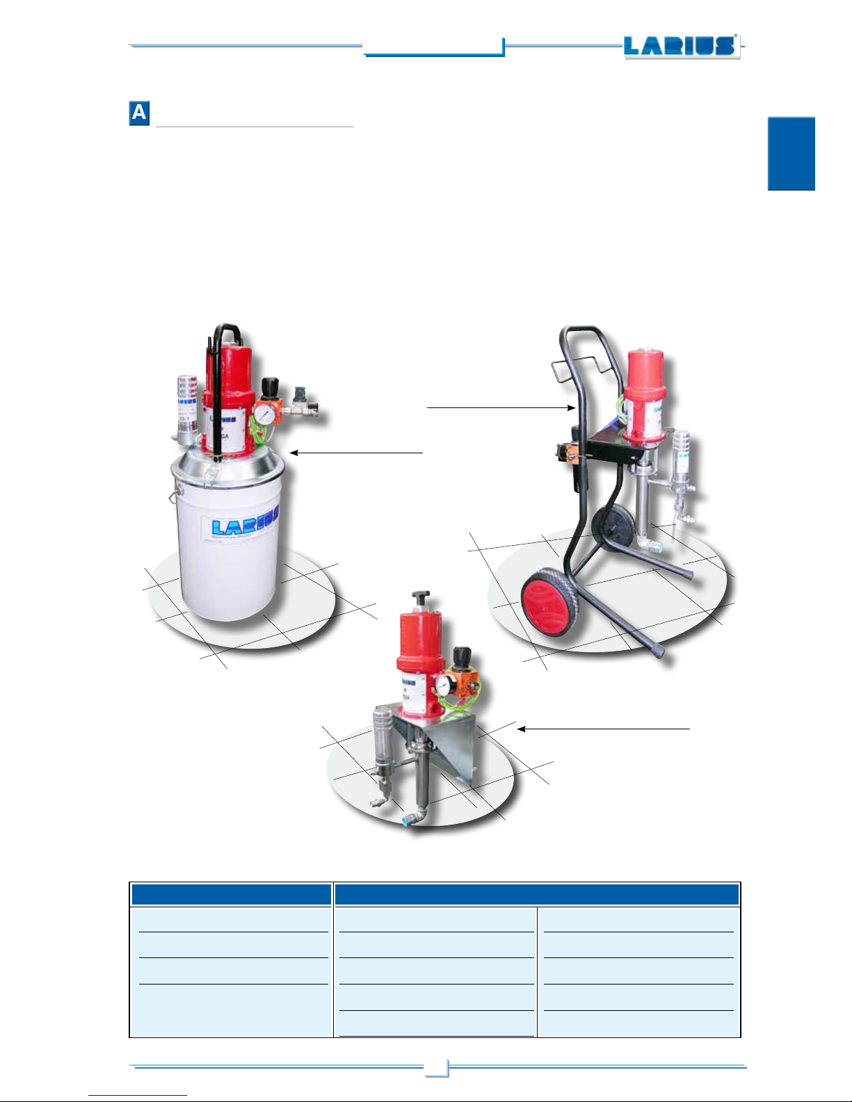
WORKING PRINCIPLE
VEGA 23:1 pump is a pneumatic pump for high pressure painting
without the use of compressed air (AIRLESS). The stainless steel
version is particularly suitable for use with water-based paints.
The pump is essentially composed of an air motor and a structure
known as “Product Pumping Unit”, or simply the “Pumping Unit”.
In the pneumatic motor, the compressed air causes the vertical
reciprocating movement of the motor piston; this movement is
transmitted through a connecting rod to the product pumping piston.
This allows the pump to suck the product and to feed it towards
the outlet.
The ratio 23:1 means that the outlet pressure of the product is 23
times higher than the pump feed air pressure.
The unit comes complete with a transportation trolley, a highpressure product filter, an air supply regulator for the pump, a
product suction tube (complete with filter) and a recirculation tube.
Our spray guns are tested and controlled in our factory and are
derivered to the customer in perfect working conditions.
For this rason, in order not to alter the characteristics of these
units, it is advisable to carefully read these instructions and to
follow them accordingly.
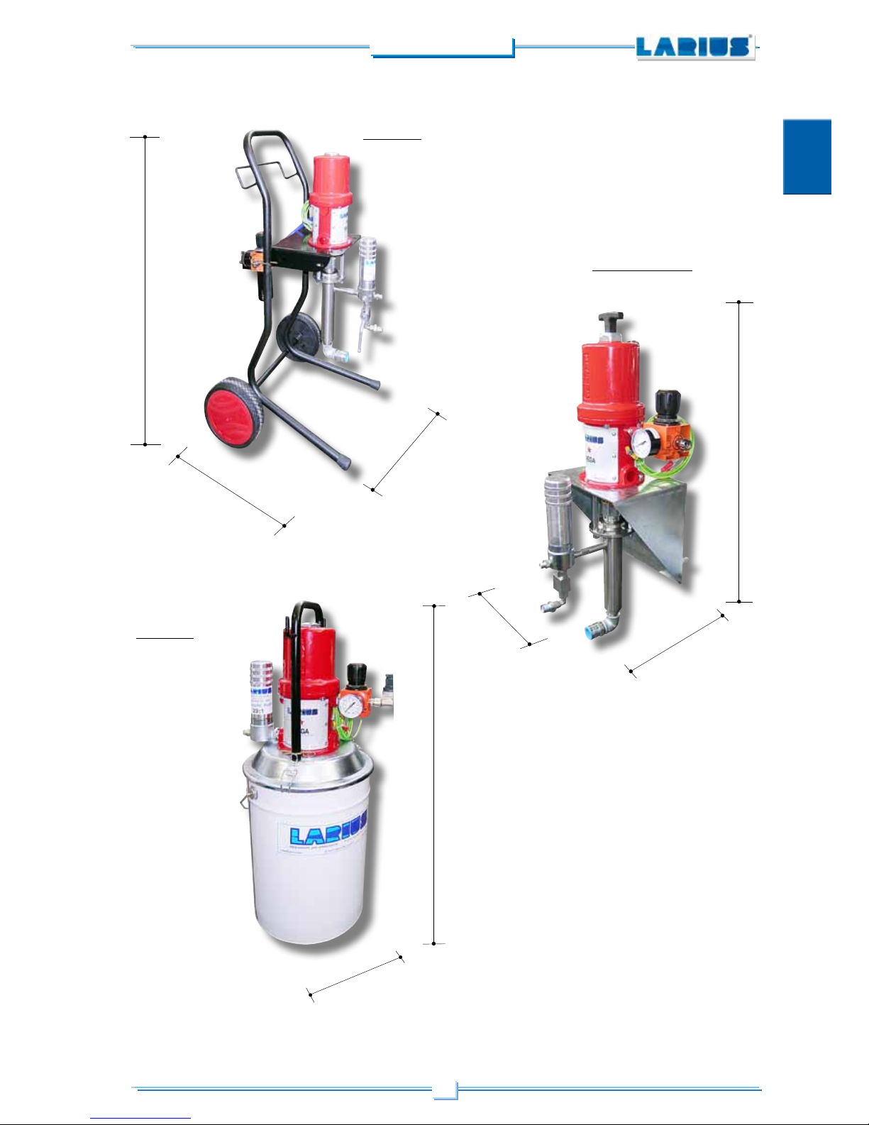
Version on tank
Trolley version
Wall bracket version
4
VEGA 23:1
English
BB
VEGA 23:1
MAXIMUM RATE
PUMP FEEDING AIR PRESSURE
AIR CONSUMPTION
AT 3 BAR
AT 5 BAR
AT 7 BAR
AIR INLET
PRODUCT INPUT
PRODUCT OUTPUT
TOTAL LENGHT
PUMPING UNIT LENGHT
WEIGHT
GASKETS
OVERALL DIMENSIONS
Trolley version A HEIGHT
B WIDTH
C DEPTH
OVERALL DIMENSIONS version on tank
D HEIGHT
E DIAMETER
OVERALL DIMENSIONS wall bracket version
F HEIGHT
G WIDTH
H DEPTH
SOUND PRESSURE LEVEL
2,6l/min (0.7 gpm)
3-8 bar (40-120 psi)
180 l/min (6.5 cfm at 40 psi)
380 l/min (13.5 cfm at 70 psi)
550 l/min (19.5 cfm at 100 psi)
3/8” GAS (F)
3/4” GAS (M)
3/8” GAS C (F)
710 mm
410 mm
16 Kg
UPPER.: teflon LOWER.: teflon
930 mm
450 mm
450 mm
780 mm
340 mm
800 mm
250 mm
290 mm
<80 dB (A)
TECHNICAL DATA
Parts of the pumpt in contact with the product
Pumping group: galvanized steel and aluminium or stainless
steel (according to versions)
Sealing balls: stainless steel AISI 420B
Gaskets: Teflon
Other parts of the pump
Motor body and motor piston: aluminium
Pneumatic motor piston rod: stainless steel
Trolley frame: painted metal sheet
These notes shall be kept in consideration in case you need
to evaluate the compatibility of a product
to be used or when you need to dispose
one or more components of the pump,
in order to schedule a suitable reciclying
of the single component according to
environment standards.
Note. The pump is supplied with bayonet coupling.
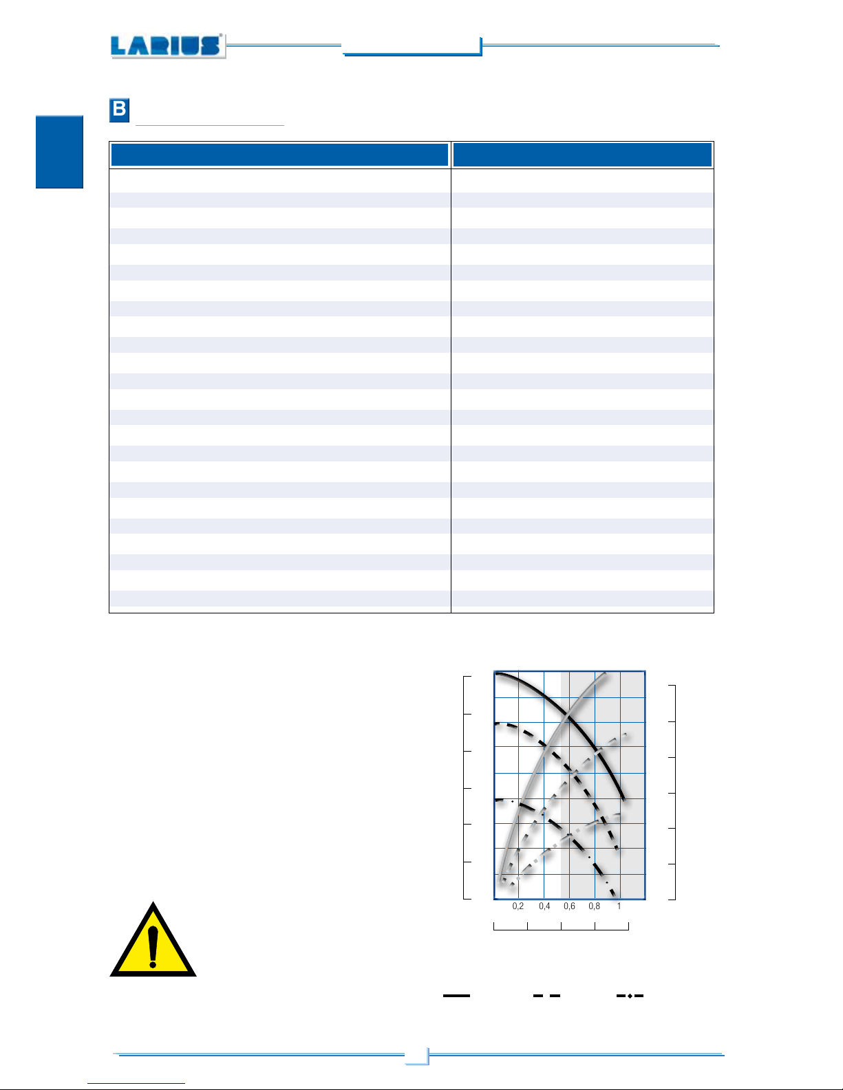
O 0,2 0,4 0,6 0,8 1 GPM 0
O 1 2 3 4 L/MIN.
PUMP RATE
PRODUCT EXIT PRESSURE
BAR
125
100
75
50
25
0
PSI
2000
1750
1500
1250
1000
750
500
250
AIR CONSUMPTION
L/MIN.
500
400
300
200
100
0
CFM
20
17,5
15
12,5
10
7,5
5
2,5
BLACK CURVE: PRODUCT EXIT PRESSURE
GREY CURVE: AIR CONSUMPTION
7 bar (100 psi) 5 bar (70 psi) 3 bar (40 psi)
The pump can operate in continuous mode when the rate is limited to
the white area. Outside this area, the speed shall be intermittent.
5
VEGA 23:1
English
H
G
F
WALL BRACKET
Version
D
E
ON TANK
Version
TROLLEY
Version
B
C
A
6
VEGA 23:1
English
7
VEGA 23:1
English
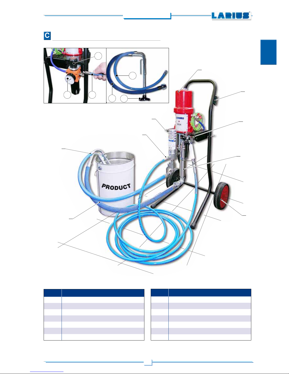
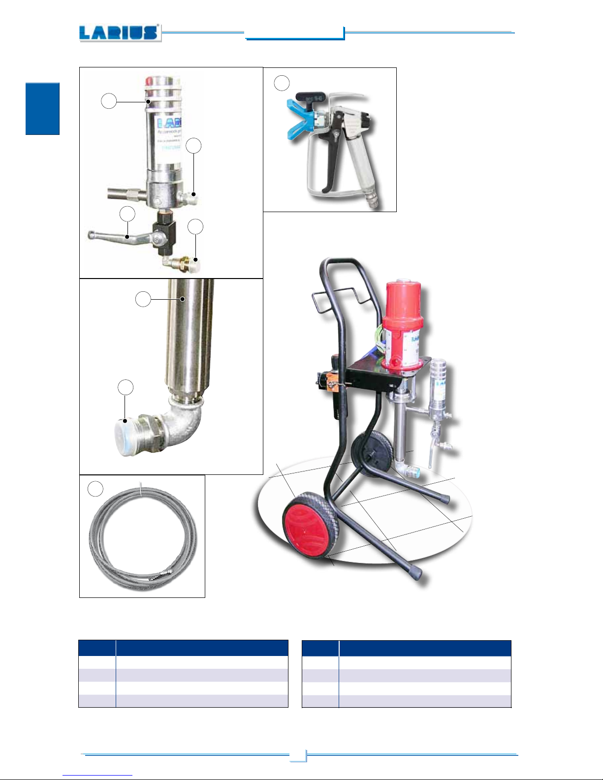
CC
POS. Description
1
Motor unit
2
Pumping unit
3
Filter unit
4
Suction hose
5
Recirculation tube
6
High pressure tube
7
Product suction filter
POS. Description
8
Wheels
9
Manual gun
10
Compressed air inlet
11
Pump feeding air pressure gauge
12
Pump feeding air pressure regulator
13
Equipment transport trolley
7
12
10
5
4
1
9
13
3
5
4
6
2
8
DESCRIPTION OF THE EQUIPMENT
11
8
VEGA 23:1
English
18
14
15
17
19
16
21
20
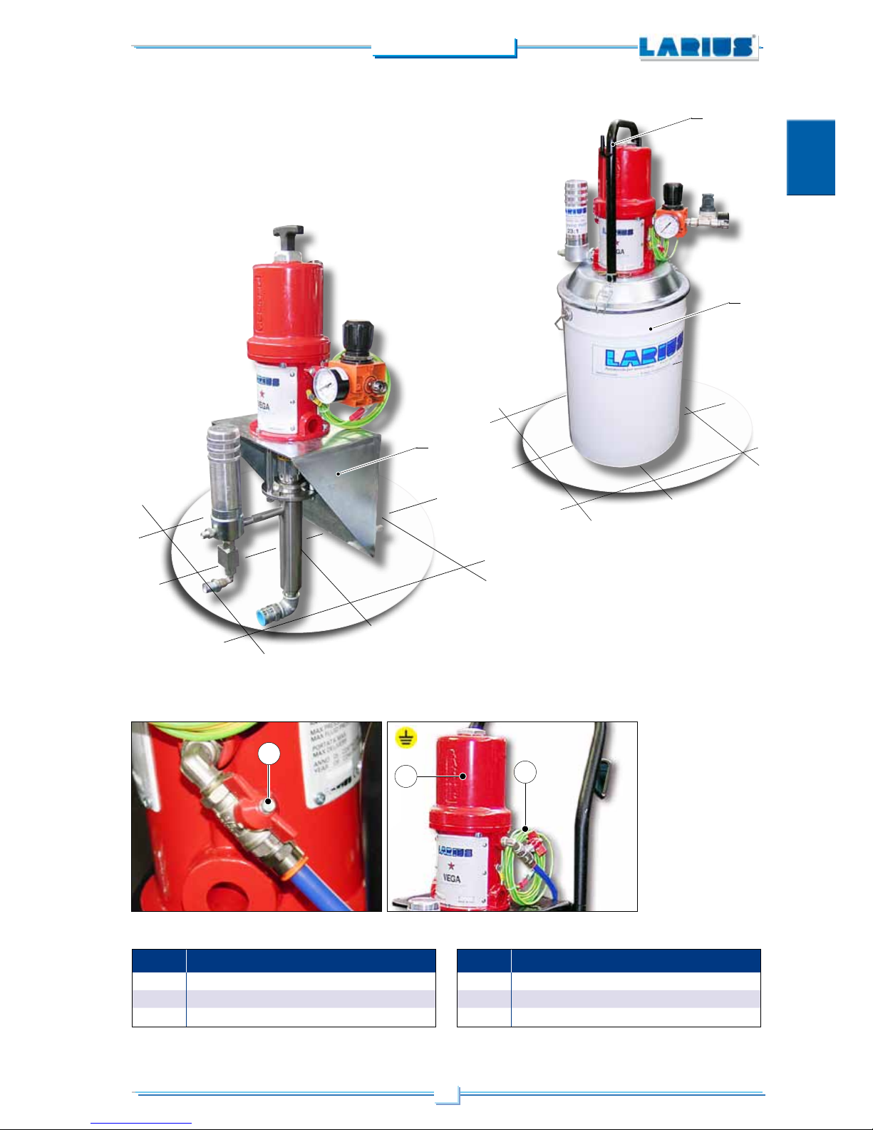
POS. Description
14
Product exit high pressure filter
15
Product exit fitting
16
Recirculation tap
17
Recirculation tube fitting
POS. Description
18
Suction hose fitting
19
Product pumping unit
20
Flexible hose air-product
21
AT250 Gun
9
VEGA 23:1
English
24
23
22
27
26
POS. Description
22
Pump air feeding opening-closing valve
23
Pump pneumatic motor
24
Grounding cable
POS. Description
25
Wall bracket
26
Lifting handle
27
Container
25
10
VEGA 23:1
English
DD
EE
• Strictly respect the orientation of the package indicated
externally by labels or symbols.
• Before installing the equipment, prepare an environment
suitable in terms of space, proper lighting, clean and
smooth floor.
•
The manufacturer declines any liability relevant to the unload
and carriage of the equipment to the workplace.
• Check the integrity of the package upon receipt. Remove
the equipment from the packaging and check that no
damage has occured during transport.
Should any damaged components be found, promptly
contact LARIUS and the shipping agent. The maximum
deadline to notify the damage is 8 days from the date of
equipment receipt. The communication must be made
by registered mail with acknowledgement addressed to
LARIUS and to the carrier.
SAFETY INSTRUCTIONS
•
THE EMPLOYER SHALL PROVIDE TO DULY TRAIN THE
PERSONNEL REGARDING THE RISKS OF ACCIDENTS,
THE SAFETY DEVICES AND THE GENERAL ACCIDENT
PREVENTION GUIDELINES PROVIDED BY THE INTERNATIONAL DIRECTIVES AND BY THE LAW IN FORCE IN THE
COUNTRY WHERE THE UNIT IS INSTALLED, IN ADDITION
TO THE STANDARDS RELEVANT TO ENVIRONMENTAL
POLLUTION.
• PERSONNEL STAFF SHALL CAREFULLY RESPECT THE
ACCIDENT PREVENTION STANDARDS IN FORCE I
N THE
COUNTRY WHERE THE UNIT IS INSTALLED, IN ADDITION
TO THE RULES RELEVANT TO ENVIRONMENTAL POLLUTION.
Carefully read the following instructions before using
the equipment.
Keep these instructions with care.
Tampering or unauthorized replacement of one or
more parts composing the equipment, the use of
accessories, tools, consumables other than those
recommended by the manufacturer, might represent
a risk of injury and raise the manufacturer from any
liability and penalty.
• KEEP THE WORKING AREA IN GOOD ORDER.
FAILURE IN RESPECTING THIS MAY CAUSE
RISK OF ACCIDENTS.
• ALWAYS KEEP A GOOD BALANCE AVOIDING
UNSAFE POSITIONS.
• BEFORE STARTING OPERATION, CAREFULLY CHECK THAT THERE ARE NO DAMAGED
COMPONENTS AND THAT THE EQUIPMENT
IS ABLE TO OPERATE CORRECTLY.
• ALWAYS FOLLOW THE SAFETY INSTRUCTIONS AND REGULATIONS IN FORCE.
• KEEP UNAUTHORIZED PERSONNEL AWAY
FROM THE WORKING AREA.
• NEVER EXCEED THE MAXIMUM OPERATING
PRESSURE
• NEV E R DIRE C T TH E G UN TOWAR D S
YOURSELF OR ANYONE ELSE. GETTING
IN TOUCH WITH THE JET MIGHT CAUSE
SERIOUS WOUNDS. IN CASE OF WOUNDS
DERIVED BY THE GUN JET, IMMEDIATELY
PROVIDE FOR MEDICAL ASSISTANCE SPECIFYING THE PRODUCT YOU WERE USING.
NEVER UNDERESTIMATE THE WOUND CAUSED BY THE INJECTION OF A FLUID.
• ALWAYS DISCONNECT THE POWER SUPPLY
AND DISCHARGE THE PRESSURE IN THE
CIRCUIT BEFORE PERFORMING ANY CONTROL OR REPLACEMENT OF EQUIPMENT
COMPONENTS.
• NEVER MODIFY ANY EQUIPMENT COMPONENT. PERIODICALLY CHECK THE COMPONENTS OF THE SYSTEM. REPLACE DAMAGED
OR WORN COMPONENTS, IF ANY.
• CHECK AND TIGHTEN ALL FITTINGS BETWEEN THE PUMP, THE FLEXIBLE HOSE AND THE
GUN BEFORE USING THE EQUIPMENT.
CARRIAGE AND UNPACKING
All unloading and handling operations of the
equipment are at User’s care who should pay the
utmost attention in order to avoid any damage to
people or things.
The unloading operations shall be carried out by
skilled and trained personnel (truck, crane ope-
rators, etc..) with suitable hoisting means able to
bear the weight of the package and to meet all
safey standards.
The personnel must be equipped with suitable
protective devices.
The disposal of packaging materials, at user’s care,
shall be performed in compliance with applicable regulations in force in the country where the equipment
is installed.
It is however good practise to dispose the packaging
materials in the most environment-friendly way.
11
VEGA 23:1
English
FF
• NEVER SPRAY FLAMMABLE PRODUCTS OR
THINNERS IN CLOSED ROOMS.
• NEVER USE THE EQUIPMENT IN PRESENCE
OF POTENTIALLY EXPLOSIVE GASES.
The high speed of the product flowing in the flexible hose may cause statical electricity showing
short sparks. It is recommended to provide a
suitable grounding for the equipment. The pump
is connected to the ground cable of the electric
supply. The gun is grounded by means of the high
pressure flexible hose. Each conductive parts near
the workplace shall be duly grounded .
Always check the compatibility of the product with
the materials composing the equipment (pump, gun,
hose and accessories) with which it can come into
contact. Do not use paint or thinners containing halogenated hydrocarbon (such as methylene chloride).
These products, when in contact with equipment
aluminum parts, can cause dangerous chemical
reactions thus representing a risk of explosion.
IF THE PRODUCT TO BE USED IS TOXIC
AVOID INHALATION AND CONTACT, BY
USING PROTECTIVE GLOVES, GOGGLES AND SUITABLE FACE SHIELDS.
ADOPT SUITABLE HEARING PROTECTION MEASURES WHEN WORKING NEAR THE EQUIPMENT.
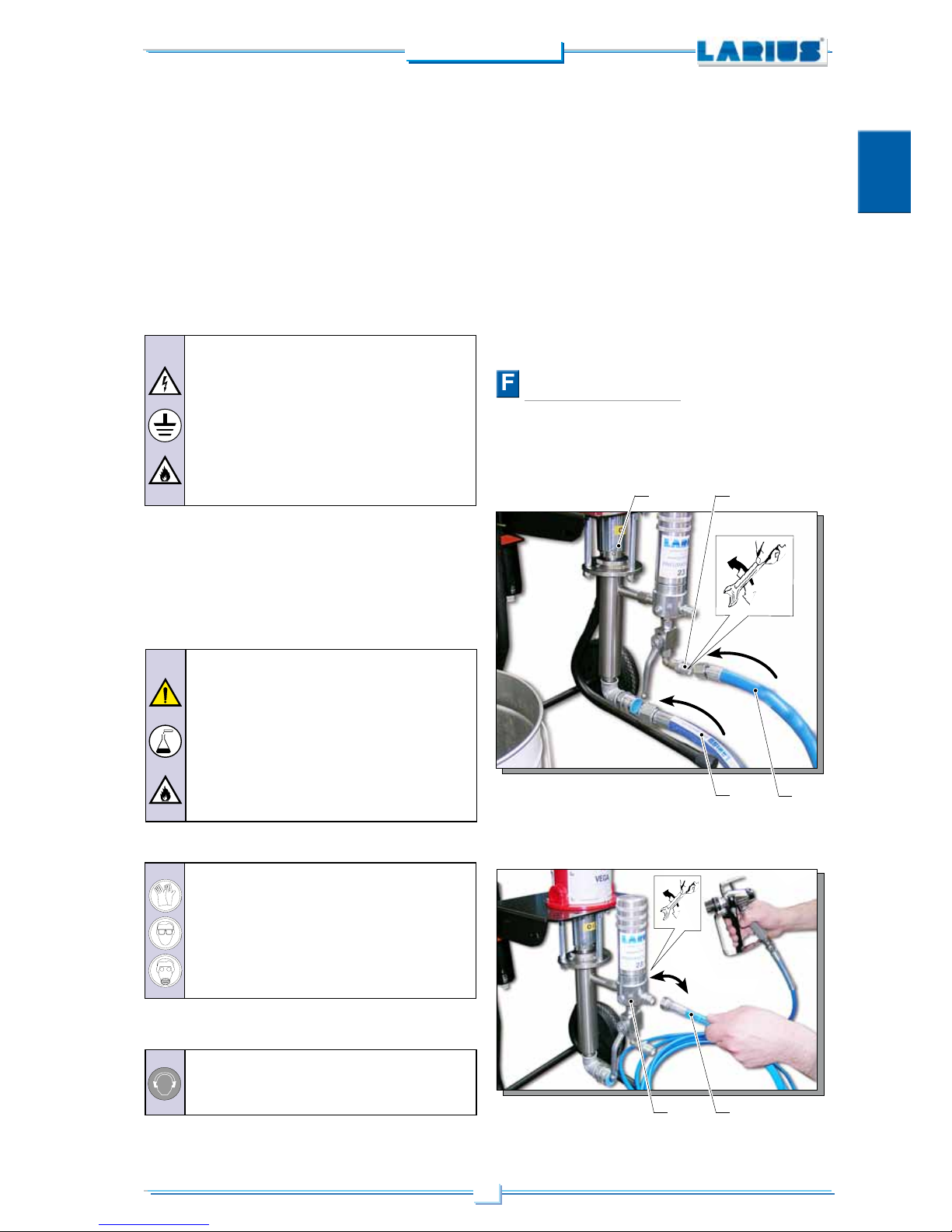
CONNECTIONS
CONNECT THE SUCTION AND RECIRCULATION HOSES
•
Connect the suction (F1) and the recirculation hoses (F2) to
the pumping unit (F3) and to the filter (F4) as indicated in the
picture.
CONNECT THE GUN HOSE
•
Connect the product feeding hose (F5) to the filter unit (F6).
•
MAKE SURE YOU KNOW HOW TO STOP THE EQUIPMENT
WHEN NEEDED. IT IS ALSO RECOMMENDED TO TRAIN
THE USERS ON THE SAFE AND CORRECT USE OF THE
EQUIPMENT BEFORE STARTING OPERATIONS.
• KEEP UNAUTHORIZED PERSONNEL FAR FROM THE
EQUIPMENT, ESPECIALLY IF THE PRODUCT TO BE USED
IS TOXIC .
• IF NECESSARY, USE WARNING SIGNALS TO KEEP ANY
UNAUTHORIZED PERSON AT A SAFE DISTANCE.
• MAKE SURE THAT THERE IS SOMEONE HEARING YOU IN
THE UNLIKELY EVENT OF AN ACCIDENT.
• ALWAYS USE THE HOSE PROVIDED IN THE
STANDARD KIT. USE OF EQUIPMENT OR
ACCESSORIES OTHER THAN THOSE RECOMMENDED IN THIS MANUAL MAY CAUSE
ACCIDENTS.
• THE FLUID CONTAINED IN THE FLEXIBLE
HOSE CAN BE VERY DANGEROUS. HANDLE
THE HOSE WITH CARE. DO NOT PULL THE
HOSE TO MOVE THE EQUIPMENT. NEVER
USE A DAMAGED OR REPAIRED HOSE.
F1
F2
F3
F5F6
F4
12
VEGA 23:1
English
NEVER use thread adhesive products on the fittings.
We recommend the use of the hose included in the
standard kit.
NEVER use a damaged or repaired flexible hose.
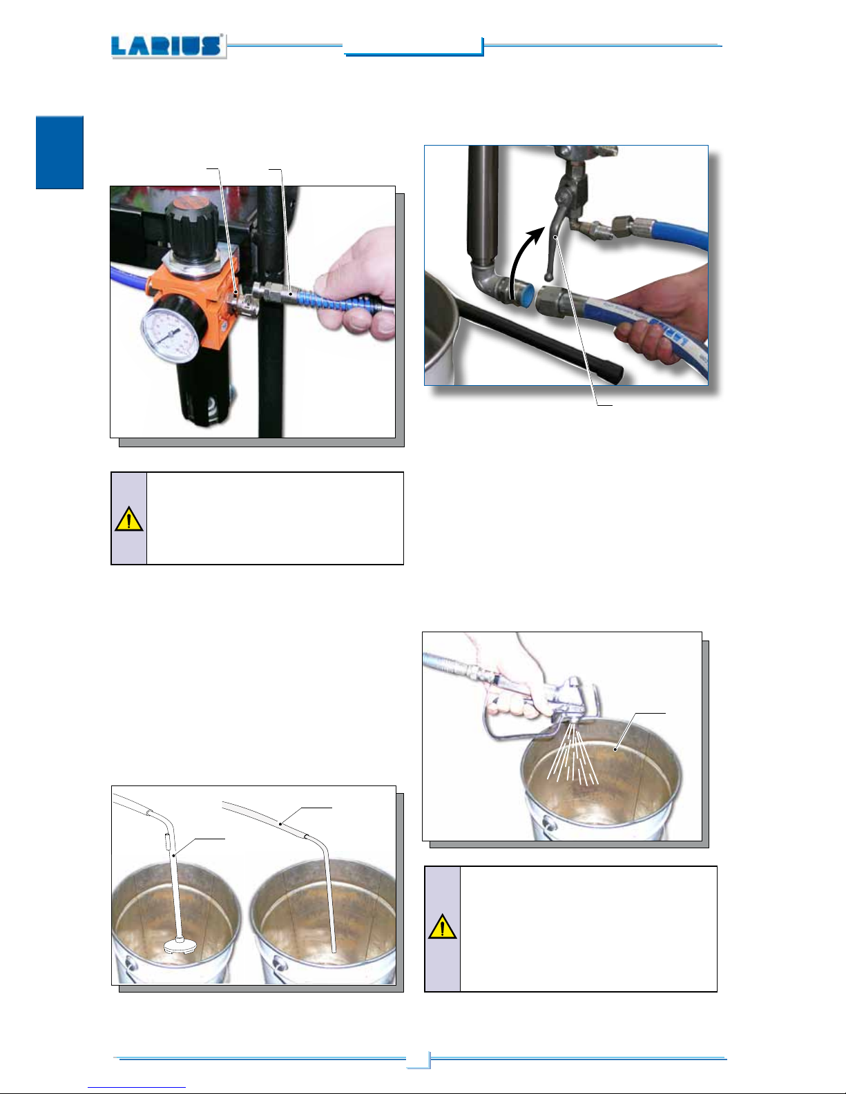
CONNECT THE FEEDING AIR HOSE
• Connect the adjustment group (F7) to the compressed air
fitting (F8).
Never operate the pump without the product, in order
to prevent the gaskets to be damaged.
Never spray cleaning liquids in close rooms. It is also
recommented to place yourself far from the pump in
order to avoid the contact with the cleaning liquids
vapours.
WASHING THE NEW EQUIPMENT
• Our equipment has been tested in our factory with a light mineral
oil which is being left inside the unit for protection. Before sucking
the product, it is necessary to duly wash with a thinner.
• Plunge the suction hose (F9) in the container of the washing
thinner.
• Plunge the recirculation hose (F10) in a collector (a metal con-
tainer is recommended).
• Open the recirculation tap (F11).
• Set the pump feeding pressure at about 3 bar and open the
air valve.
F10
F9
F11
• The pump will start and will discharge the oil for the recirculation
hose. Close the recirculation tap as soon as the clean thinner
begins to flow.
• Take the suction hose out of the product container.
• At this point place the gun against the collector (F12) and press
the trigger in order to discharge the residual oil. Release the trigger
as soon as the clean thinner begins to flow.
• Direct the gun against the thinner container and press the trigger
in order to recover the clean thinner left inside the pump.
• As soon as the pump begins to work in an accelerated way
(“vacuum") close the air valve.
F12
F7
F8

13
VEGA 23:1
English
Paints and products without pigments and
charges. Very fine and with low viscosity
paints and lakes, enamels, primers, polyesters, oils, degreasers amd detergents,
polyurethan paints.
Normal lakes or having higher viscosity,
fillers, produts with a coarse grinding, rust
preventers, vinyl produts for coverings, etc.
Same products with a high yield, epossidic
resins, dispersion for the building industry,
applications with high thickness.
NOZZLE Ø
PRODUCT
mm
0,18 ÷ 0,28
inch
0,007” ÷ 0,011”
mm
0,33 ÷ 0,62
inch
0,013” ÷ 0,025”
mm
0,68 ÷ 0,94
inch
0,027” ÷ 0,037”
NOZZLE SIZE
ACCORDING TO THE PRODUCT
• At this point the unit is ready. Should water paints be used,
it is advisable to wash with soap water and then with clean
water, besides the washing with cleaning liquid.
PREPARATION OF THE PAINT
• Make sure that the product is suitable to be sprayed.
• Duly mix and filter the product before use. We recommend the
use of LARIUS METEX filters with fine-mesh (Rif. 214) or large
mesh (Rif. 215).
Make sure that the product is suitable to be
used with the materials employed for the unit
manufacturing. For this purpose, refer to the
product supplier.
• Rotate clockwise the pressure adjustment knob (F10) so that
the pump starts to work.
• When the product has been duly mixed, the product will flow
from the recirculation hose. (F2)
If the product does not flow, this means it is too thick and it
is necessary to dilute it again until a correct flow is achieved.
Let the product flow for a short time. At this point, the machine
is ready to work.
OPERATION
F10
PRODUCT PREPARATION
• Make sure that the product and the thinner are suitable to
be sprayed. Make sure that the thinner is suitable to be used
with the product to be sprayed. Make sure that the product
has been duly filtered and mixed.
NOZZLE AND FILTERS
• The nozzle and the filter shall be suitable for the gun, according to the product to be sprayed and to the operation to be
carried out (refer to the assembly tables and instructions).
• This table is for indication only. The adapatability of a certain
product to a determined nozzle changes according to different
aspects. If previous experiences are lacking, a practical test
is always necessary. A nozzle, which has been duly chosen,
will give as result a neat jet without pulsations and gives a
perfect praying of the product.
• An inconstant spray, slightly marked on the sides, might
indicate a too low pressure. If the maximum pressure has
already been reached, it is then necessary to choose a smaller
nozzle. With the exclusion of some products, which can be
atomized at high pressures only, it is advisable not to exceed
the value of 140-170 Atm (high pressure could cause mist).
• Considering an equal speed of application, a
nozzle with a spraying angle of 20° lays down a
film having a thickness which is averagely double
in respect to the one which can be obtained with
the same nozzle with an angle of 60°.
• An excessive diameter of the angle could result
in an anomalous pressure drop.
• When ordering a nozzle, choose accurately the
reference number on the list of the nozzles.
START SPRAYING OPERATIONS
• Use the equipment only after having completed all the
adjustment operations described in the previous paragraph.
Before using the equipment, check all the
connection fittings on the various components
(pump, flexible hose, gun, etc.)
GG

14
VEGA 23:1
English
• Use the provided lubricant (G1) (rif. 16325) in order to make
the sliding of the piston easier inside the sealing pack and
interpose oil to air.
G1
Daily check that the ring nut is covered with hydraulic oil (rif. 16325); the oil improves the sliding of
the piston and prevent the product, coming out
from sealing gaskets, to dry once the equipment
is stopped.
• Fix the spraying nozzle on the gun, choosing the suitable
nozzle according to the characteristics of the product to be
used and the kind of operation to be performed.
Plunge the suction hose (G1) and the recirculation hose (G2) in the product container (G3).
G1
G2
G3
• Open the recirculation tap.
• When the air tap (G4) is closed, make the air flow from the
compressed air supply.
Check on the pressure gauge (G5) that the pressure does not
exceed 2-3 Atm [adjust it with the knob (G6) of the regulator].
With an empty pump, a higher pressure might
cause a quick and violent movement of the piston,
which could be dangerous. Beside this, starting
with the max pressure (6-8 bar) the pump will not
be able to fill the chamber considering the high
speed of the cycle.
• Open the air tap (G4).
G4
G6
G4
G5

15
VEGA 23:1
English
• Should the cycle speed be too high, decrease the feeding
pressure or slightly close the air tap (G4). Set the minimum
pressure necessary for the operation.
At the end of the work, stop the pump in the lower position
in order to prevent the product to dry on the piston and to
damage the gaskets.
ADJUSTING THE SPRAYING JET
• Slowly turn clockwise the pressure adjustment knob until
the suitable value able to grant a proper atomization of the
product is reached.
• An inconstant spray, slightly marked on the sides, might indicate a too low pressure. On the contrary a too high pressure
might cause mist (overspray) and product dispersion.
• Do not spray without the contemporaneous advancement of
the gun (right-left) in order to avoid an anomalous thickness
of the paint.
• Always proceed with regular and parallel passages.
• Keep a constant distance (25/30 cm) between the nozzle and
the support to be sprayed and keep yourself perpendicular
to it.
• Avoid to work with maximum pressure.
• Let the product flow for a few seconds. Then close the recirculation tap. The pump will continue to work until the product
will fill the high pressure flexible hose up to the gun, then it
will stop.
NEVER direct the gun towards yourself or anyone
else.
Getting in touch with the jet might cause serious
wounds. In case of wounds derived by the gun jet,
immediatly provide for medical assistance specifying the product you were using.
Recirculation-safety valve: during the operation
at the maximum pressure availble, when releasing
the gun trigger, you can assist to brisk pressure
increasings. In this case the recirculation-safety
valve automatically opens, discharging part of the
product from the recirculation hose. It then closes
in oder to set the previous working conditions.
H4
CLEANING AT THE END OF
THE WORK
• Remove the suction (H1) and the recirculation hoses (H2)
from the product container (H3) by going on spraying (H4),
until the pump is completely empty.
H3
H2
H1
• Plunge the suction (H5) and the recirculation hoses (H6)
in the thinner container (H7). Set pressure to the mimimum
and by keeping the nozzle below the thinner level in the
container, spray until the thinner has been recycled during
three or five minutes.
HH

16
VEGA 23:1
English
• By going on spraying, lift the suction (H8) and the recirculation
hoses (H2), in order to drain out all the thinner. Then stop the
pump, by closing the air tap.
H2
H1
H7
H8
• After washing, in case a long period of downtime is foreseen
or if a water-based product has been used, it is advisable
to lubricate the inner parts (pumping group), by sucking the
hydraulic oil with the pump, without discharging it.
Before using the equipment, make sure to follow
the cleaning procedure.
ROUTINE MAINTENANCE
Periodically check the air supply line to the pump.
Make sure that the air is always clean and lubricated.
I1
Before carrying out any control or maintenance
operation on the pump, always close the compressed air supply and discharge the pressure
in the circuit.
Rif. 16325
LUBRICATING THE GASKETS RING NUT
• Periodically check (and in any case each time the pump
is started after a long period of downtime) that the
gaskets ring nut is tight in order to avoid any product
leak.
• Weekly check that the gaskets ring nut (I1) is tight.
To tighten the gaskets ring nut (I1) use the provided
wrench (I2). The ring nut shall be duly tightened so
that to prevent any leak but this shall not be excessive
in order to avoid the blocking of the pumping piston
and the wear of the sealing gaskets. Should the product leak, provide to replace the upper gaskets. This
adjustment shall be carried out after having removed
the air feeding tube and having discharged the pressure.
I2
OIL
II

17
VEGA 23:1
English
PRODUCT SUCTION FILTER
I3
CLEANING THE SUCTION FILTER
• Disassemble and clean the product suction filter (I3).
PRODUCT OUTPUT FILTER
I4
CLEANING THE PRODUCT SUCTION FILTER
• Disassemble and clean the high pressure filter for product
output (I4).
Daily check that the ring nut is covered with hydraulic oil (rif. 16325); the oil improves the sliding of
the piston and prevent the product, coming out
from sealing gaskets, to dry once the equipment
is stopped.
REPLACEMENT OF THE
PUMPING UNIT GASKETS
• Unscrew the filter group (J1) from the pump housing (J2).
•
Unscrew the three self-locking nuts (J3) and remove the
pumping unit (J4), by unscrewing it from the motor piston rod.
J1
J2
J3J4
JJ

18
VEGA 23:1
English
• Remove the split pin (J6).
J6
• Unscrew the gaskets ring nut (J7) form the pump housing.
Unscrew the group of the suction valve (J8) .
When reassembling the seat of the valve (J12) in
the piston (J9) the thread shall be covered with
threads braking adhesive.
• Remove the piston (J9) from the pump housing and replace
the gaskets upper set (J10) or lower set (J11) respecting
the assembly order of the same.
J10
J11
J12
J9
J8
J7

19
VEGA 23:1
English
CLEANING AND REPAIRING
THE SUCTION VALVE
• If the suction valve is seized in the housing of the pump, inject
oil around the thread and knock slightly around the body of
the pump by means of a wooden mallet. Unscrew the valve
from the pump body.
Remove the pin (K1) holding the ball, as well as the ring
stop (K2), the O-ring (K3), the ball (K4). Clean all the parts,
inspect them and reassemble all the parts in the same order,
by screwing the valve in its seat.
MANUAL SERVICING OF THE
PNEUMATIC MOTOR
• The pump feeding air pressure shall never be higher than the
maximum value provided by the technical data sheet. Failure
in respecting this value could cause the blocking of the valves
of the pneumatic motor in the cycle inversion position.
• In order to restart a blocked motor, close the air feeding valve
and release the air pressure in the circuit. This should allow
the return of the valves in the correct position.
• Should the motor be blocked, proceed as follows:
- close the air supply to the pump and discharge the residual
pressure in the circuit;
K1
K2
K3
K4
KK
LL

20
VEGA 23:1
English
L1
L2
DISASSEMBLING THE
MOTOR
• Place the piston to the upper point of its run and unscrew
the plug (M1). Block the guide rod (M2) with clamping pliers
and replace the plug (M1) with a M8 nut (M3).
- unsprew the plug (L1) and pull it upwards together with the
guide rod (L2), by making thus manually trig the run inversion
group.
- screw the plug.
• Remove the screws (M4).
M2
M3
M4
M1
MM

21
VEGA 23:1
English
•
Take out the cylinder (M5) with the utmost care from the piston,
without inclining it in order to avoid damages to the inner walls
of the same.
•
By keeping the hands far from the cross piece (M6), press
on the rocker arm (M7) so that the cross piece (M6) trigs
downwards (drain valves closed).
• Unscrew the two counternuts (M8) which block the valve screws.
• Remove the valve screws (M9) and check the wear condition
of the gaskets (M10).
M5
M6 M7
M8
M8
M10
M9

22
VEGA 23:1
English
A
3,5 mm
•
Block the roller (M11) with the pliers and by pressing on the
spring (M12), remove it from its seat. In this way, it will be
possible to remove all the run inversion group.
•
Check the condition of each piece, in particular of the gaskets
(M13) and the O-ring (M14), (M15) and (M16).
Control that the inner walls of the cylinder are not scratched.
Before reassembling all parts, lubricate them with light and
water proof grease.
•
Adjust then the distance (A) between the gaskets and the
surface of the piston. This adjustment shall be done with the
cross piece (M7) down and it can be better done by using our
special metering device.
After having reassembled all parts, before connecting the
group to the pump, test it by feeding a small quantity of air
(3-4 bar).
• For a correct reassembly, refer to the pumping group detailed
drawing, by following the disassembly instructions in reverse
order.
M11
M13
M12
M13
M16
M15
M14

23
VEGA 23:1
English
TROUBLESHOOTING
• The pump does not work
• The operation of the pump is ac-
celerated and without pressure
• The pump works but it does not
stop when the chamber is full (the
pumping unit slowly moves up
and/or down)
• By pressing the gun trigger, the
pressure of the product highly
decreases
• Feeding air is not sufficient.
• Product outlet line is clogged;
• Product inlet line is clogged;
• Pneumatic motor is blocked in the
position of cycle inversion;
• Some components of the pneumatic
motor are damaged ;
• The product is lacking;
• The pump is sucking air;
• The gaskets of the pumping rod are
worn;
• The suction valve is worn or partially
clogged;
• The suction filter is clogged;
• The suction filter is too thin;
• The gaskets of the pumping shaft are
worn;
• The suction valve is worn or partially
clogged;
• The feeding valve is worn or partially
clogged;
• Upper gaskets are worn;
• Gun nozzle is too big or worn
• Gun filter and the filter sieve for product
outlet are too thin
• Check the air supply line. Increase
the diameter of the feeding air pipe;
• Open the recirculation nozzle and
check that the pump starts. Unscrew
the high pressure filter and clean and/
or replace the filter sieve. Clean and/
or replace the gun filter;
• Clean the suction filter;
• Decrease the feeding pressure;
• Manually service the pneumatic
motor;
• Disassemble the motor and inspect
it;
• Add product;
• Check the flexible suction hose;
• Replace the lower gaskets;
• Disassemble the suction valve. Clean
and/or replace any worn component.
• Clean and/or replace the two discs
of the suction filter;
• Remove the fine-mesh filter disc and
leave only the large-mesh filter disc.
• Replace the lower gaskets
• Disassemble the suction valve and
clean and/or replace any worn detail
• Disassemble the feeding valve and
clean and/or replace any worn detail
• Tighten the gaskets ring nut
• Replace it with a smaller one
• Replace them with larger-mesh filters
Solution
Possible cause
Faults
Before performing any inspection or replacement of the pump components, make always
sure to close the compressed air supply and discharge the residual pressure in the circuit.
NN

24
VEGA 23:1
English

25
VEGA 23:1
English
SPARE PARTS
SPARE PARTS
Complete trolley
page 36
Paints suction system
page 39
Air regulation unit
AIRLESS - MISTLESS
version page 37-38
Complete pneumatic motor Rif. 9100
page 26
Vega stainless steel split
pump complete pumping
unit page 28
Vega split pump complete
pumping unit
page 30
Vega split pump on tank
complete pumping unit
page 32
Vega split pump on tank
page 34
High pressure gun AT 250
page 40
OO
PPQQSS
XX
WWRRTT
U-VU-V

26
VEGA 23:1
English
VEGA PUMP 23:RIF. 9100 COMPLETE PNEUMATIC MOTOR
ATTENTION: always indicate code and quantity of each requested detail
L A R I U S
V E G A
1
2
3
9
9
10
10
11
11
12
13
17
18
4
5
6
7
8
14
15
16
21
22
23
19
24
25
27
32
29
30
26
31
33
34
35
29
28
36
38
37
20B
20
20A
OO

27
VEGA 23:1
English
* Kit 40040: motor gaskets kit
** Kit 40401: cross piece screws kit
Pos.
Complete pneumatic motor
Vega pump 23:1
Plug
O-Ring
Cylinder motor
Roller
Spring
Fork
Fork gudgeon
Rocker lever
M8 Nut **
Washer **
Gasket
Bushing **
Cross piece
O-Ring *
Guide
Rubber valve
M3 screw
Cross piece guide spring
Motor piston
Complete valve screw
1
2
3
4
5
6
7
8
9
10
11
12
13
14
15
16
17
18
19
20
1
1
1
2
2
2
2
1
4
4
4
2
1
1
1
2
2
2
1
1
Pos.
20A
20B
21
22
23
24
25
26
27
28
29
30
31
32
33
34
35
36
37
38
Rubber valve
Valve screw
Washer
Piston rod
Complete washer
O-ring *
O-ring
Motor support
Grounding plate
M6 screw
Felt gasket
M8 screw
Front label
Upper label
M4 screw
Tie rod
M10 Nut
Elbow 3/8”
Ball valve
Quick coupling 3/8” ø 12
1
1
1
1
1
1
1
1
1
1
2
4
1
1
12
3
3
1
1
1
91000
,
96001
95075
91028
96005
96006
96007
96024
96008
4108
32024
96111
96112
91029
91034
91033
96009
91030
91032
91035
96027
96014
96015
91036
91043
96017
91037
91038
91042
96210
96211
96340
34008
91039
91040
96028
91006
96080
96214
91101
96215
Code Description Q.ty Code Description Q.ty
*
**
*
**
*
**
*
**

28
VEGA 23:1
English
STAINLESS STEEL SPLIT VEGA PUMP 23:1
COMPLETE PUMPING UNIT
ATTENTION: always indicate code and quantity of each requested detail.
Complete line filter Complete pumping unit
10
12
14
15
16
17
18
19
20
13
21
22
23
24
25
26
27
28
30
29
32
31
33
34
35
36
11
37
38
15A
23A
1
2
3
4
5
6
7
8
9
10
11
12
13
10
PP

29
VEGA 23:1
English
Pos.
Complete pumping unit
Oil cup
O-ring
Gaskets ring nut
Complete cup
Female V ring
Ptfe gasket
Polyethylene gasket
Male V ring
Pumping unit housing
O-ring
Split pin
Piston rod
Washer
Male V ring
Ptfe gasket
Code Description
,
10
11
12
13
*14
*15
*15A
*16
17
18
*19
20
21
*22
*23
Q.ty
1
1
1
1
1
2
2
1
1
1
1
1
1
1
2
Pos. Code Description Q.ty
*23A
*24
*25
26
27
28
29
*30
*31
32
33
34
35
36
37
38
Polyethilene gasket
Female V ring
Ø5/16* Ball
Pumping unit piston
Ball guide
Ring
Ball locking pin
O-ring
Ø1/2* Ball
Suction valve
Elbow
Suction hose fitting
Bushing
Filter fitting
Gasket
Liner
2
1
1
1
1
1
1
1
1
1
1
1
1
1
1
1
98440
91001/1
3429
98506
91001
98454
91031
91048
98456
98455
91008
3323
98452
98458
98460
91022
91049
98462
96090
98463
98466
98368
98370
96093
96094
98373
98374
98376
96099
98378
96083
91512
* Kit 40045: spare kit
Pos.
Complete line filter
3/8” gas plug
Filter tank
Sieve spring
Filter sieve 200m
Filter sieve 100m
Filter sieve 60m
Sieve support
Code Description
1
2
3
4
5
Q.ty
1
1
1
1
1
1
1
Pos. Code Description Q.ty
6
7
8
9
10
11
12
13
O-ring
1/4” gas-16x1,5 nipple
Filter base
Adapter 1/4” con-cil
Copper gasket 1/4”
Ball valve 1/4”
Elbow MF 1/4”
Adapter 1/4” - M20x2
1
1
1
1
2
1
1
2
98387
98385
98384
96202
95221
95220
95219
96207
96203
98383
98380
3110
32012
98325
98377
96065

30
VEGA 23:1
English
VEGA SPLIT PUMP 23:1 COMPLETE PUMPING UNIT
ATTENTION: always indicate code and quantity of each requested detail.
10
12
14
15
16
17
18
19
20
13
21
22
23
24
25
26
27
28
30
29
32
31
33
34
35
36
11
37
38
15A
23A
1
2
3
4
5
6
7
8
9
10
11
12
13
10
Complete line filter Complete pumping unit
QQ

31
VEGA 23:1
English
Pos.
Complete pumping unit
Oil cup
O-ring
Gaskets ring nut
Complete cup
Female V ring
Teflon gasket
Polyethilene gasket
Male V ring
Pumping unit housing
O-ring
Split pin
Piston rod
Washer
Male V ring
Teflon gasket
Code Description
,
10
11
12
13
*14
*15
*15A
*16
17
18
*19
20
21
*22
*23
Q.ty
1
1
1
1
1
2
2
1
1
1
1
1
1
1
2
Pos. Code Description Q.ty
*23A
*24
*25
26
27
28
29
*30
*31
32
33
34
35
36
37
38
Polyethilene gasket
Female V gasket
Ø5/16* ball
Pumping unit piston
Ball guide
Ring
Ball locking pin
O-ring
Ø1/2* ball
Suction valve
Elbow
Suction hose fitting
Entry liner
Filter fitting
Gasket
Liner
2
1
1
1
1
1
1
1
1
1
1
1
1
1
1
1
91027
91001/1
3429
98506
91001
98454
91031
91048
98456
98455
91008
3323
98452
98458
98460
91022
91049
98462
96090
98463
91714
96092
98370
96093
96094
98373
95089
96098
96099
98378
96083
91512
* Kit 40045: spare kit
Pos.
Complete line filter
3/8” gas plug
Filter tank
Sieve spring
Filter sieve 200m
Filter sieve100m
Filter sieve 60m
Sieve support
Code Description
1
2
3
4
5
Q.ty
1
1
1
1
1
1
1
Pos. Code Description Q.ty
6
7
8
9
10
11
12
13
O-ring
1/4” gas-16x1,5 nipple
Filter base
Adapter 1/4” con-cil
Copper gasket 1/4”
Ball valve 1/4”
Elbow MF 1/4”
Adapter 1/4” - M20x2
1
1
1
1
2
1
1
2
96200
95214
96201
96202
95221
95220
95219
96207
96203
96206
96204
96208
33012
33013
5255
33015

32
VEGA 23:1
English
VEGA SPLIT PUMP ON TANK 23:1 COMPLETE
PUMPING UNIT
L A R I U S
V E G A
10
11
12
13
14
15
16
17
18
19
20
21
22
23
24
25
26
27
28
29
30
36
32
33
34
35
32
34
33
31
37
1
2
3
4
5
6
8
7 9
Complete line filter
Complete pumping unit
ATTENTION: always indicate code and quantity of each requested detail.
RR

33
VEGA 23:1
English
Pos. Code Description Q.ty
Complete line filter
3/8” gas plug
Filter tank
Sieve spring
Filter sieve 200m
Filter sieve100m
Filter sieve 60m
Sieve support
O-ring
1/4” gas-16x1,5 nipple
Filter base
1/4” gas plug
,
1
2
3
4
5
6
7
8
9
1
1
1
1
1
1
1
1
1
1
2
96200
95214
96201
96202
95221
95220
95219
96207
96203
96206
96204
96205
Pos.
Complete pumping unit
Filter fitting
Gaskets ring nut
Female V ring
Teflon gasket (standard)
Leather gasket
Male V ring
Pumping unit housing
O-ring
Split pin
Piston rod
Washer
Male V ring
Teflon and glass gasket
(standard)
Pure Teflon gasket
Leather gasket
Code Description
,
10
11
12
*13
13A
14
15
16
*17
18
19
20
*21
21A
21B
Q.ty
1
1
1
4
1
1
1
1
1
1
1
1
4
1
1
Pos. Code Description Q.ty
22
*23
24
25
26
*27
28
*29
30
31
32
33
34
35
36
37
Female V ring
Ø5/16* ball
Pumping unit piston
Ball guide
Ring
O-ring
Ball locking pin
Ø1/2* ball
Suction valve
Fitting
Fitting
Hub
Hub nut
Product tube
Fitting
(3 leather 1 teflon)
Complete pneumatic motor
1
1
1
1
1
1
1
1
1
1
2
2
2
1
1
91710
91730
91001/2
91002
91003
91004
91005
91007
91008
3323
91009
91011
91012
91014
91022
91015
91013
96090
91017
91714
96092
96093
96096
96094
91713
91712
91715
91716
91717
91718
91719
91000
* Kit 40045: spare kit

34
VEGA 23:1
English
VEGA SPLIT PUMP 23:1 ON TANK RIF. 91700
L A R I U S
V E G A
14
2
13
8
7
6
4
5
1
15
4
18
17
16
10
9
11
12
19
3
ATTENTION: always indicate code and quantity of each requested detail.
SS

35
VEGA 23:1
English
Pos.
Complete pneumatic motor
Complete line filter
Complete pumping unit
Code Description
1
2
3
Q.ty
1
1
1
91000
96200
91710
Pos.
Complete air regulation unit
3/8” gas C nipple
3/8” gas tap
Pressure regulator
Bajonet coupling
Pressure gauge
Code Description
4
5
6
7
8
Q.ty
2
1
1
1
1
91735
91020
91101
91736
10103
96259
Pos.
Complete tank filter
Filter tank
Fine-mesh filter disc
Large-mesh filter disc
Spring
Code Description
9
10
11
12
Q.ty
1
1
1
1
91725
91726
35006
35007
35008
Pos.
Complete container
Container handle
Split pin
M6 screw
Container cover
Washer
M6 Nut
Container
Code Description
13
14
15
16
17
18
19
Q.ty
1
2
3
1
3
3
1
91740
91741
84007
91062
91742
54003
91026
91743

36
VEGA 23:1
English
COMPLETE TROLLEY
7
2
3
4
5
6
1
6
8
9
Pos.
Complete trolley
Trolley handle
Trolley frame
Trolley plate
Wheel
Feet
Code Description
1.
2
3
4
5
Q.ty
1
1
1
2
2
Pos. Code Description Q.ty
6
7
8
9
10
Wheel washer
Screw
Washer
Nut
Split pin
6
2
2
2
2
96320
16271
16272
16954
91023
37403
91047
8047
95063
91026
84007
10
10
7
8
9
6
4
6
5
ATTENTION: always indicate code and quantity of each requested detail.
TT

37
VEGA 23:1
English
Pos.
Complete unit
3/8 tube Ø 12 quick coupling
FR group
UNI 5588 M6 Nut
Ø 6 washer
Code Description
1.
2
3
4
Q.ty
-
1
1
2
2
Pos. Code Description
5
6
7
8
TCE UNI 5931 M6x22 screw
Bajonet coupling
Pressure gauge
Rilsan tube
2
1
1
1
96250
96015
91107
91026
95063
8047
10103
96259
96217
AIRLESS VERSION Rif. 96250 AIR REGULATION UNIT
Q.ty
ATTENTION: always indicate code and quantity of each requested detail
1
2
3
4
5
6
7
8
UU

38
VEGA 23:1
English
Pos.
Complete unit
3/8 tube Ø 12 quick coupling
Pressure gauge
Group RL 3/8 + bracket
3/8 mm conic adapter
3/8 “T” female fitting
Bajoinet coupling
3/8 1/4 mm CON-CON adapter
Pressure gauge
Code Description
1
2
3
4
5,
6
7,
8
Q.ty
-
1
1
1
1
1
1
1
1
Pos. Code Description Q.ty
9
10
11
12
13
14
15
16
17
Air regulator
1/4 MF adapter
MF 1/4 elbow
1/4 cupper gasket
1/4 mm adapter
Pressure gauge bracket
UNI 5588 M6 nut
Ø 6 washer
TCE UNI5931 M6x22 screw
1
1
1
1
1
1
2
2
2
96262
96216
96259
91107
91020
3379
10103
3560
8167
3344
8055/1
5255
33012
3289
510510
91026
95063
8047
MISTLESS VERSION Rif. 96262 AIR REGULATION UNIT
9
1
2
3
4
5
6
10
7
11
8
12
13
15
16
17
14
17
16
15
ATTENTION: always indicate code and quantity of each requested detail.
VV

39
VEGA 23:1
English
Pos.
Paints suction system with split
suction tubes
Filter assembly
Suction hose complete with filter
with split suction unit
Filter tank
Thin filter disc (80 mesh)
Thick filter disc (25 mesh)
Spring
Split recirculation tube
Code Description
1
2
3
4
5
6
7
Q.ty
1
1
1
1
1
1
1
Pos. Code Description Q.ty
1
2
3
4
5
6
7
Paints suction system with stain-
less steel suction tubes
Asssieme filtro di fondo
Suction hose complete with filter
with split suction unit
Filter tank
Thin filter disc (80 mesh)
Thick filter disc (25 mesh)
Spring
Split recirculation tube
1
1
1
1
1
1
1
16110
35020
16608
35005/1
35006
35007/1
35008
16609
16111
35020
16612
35005/1
35006
35007/1
35008
16613
PAINTS SUCTION SYSTEM
7
2
3
4
5
6
1
ATTENTION: always indicate code and quantity of each requested detail.
WW

40
VEGA 23:1
English
ATTENTION: always indicate code and quantity of each requested detail.
A
1
2
3
4
6
12
5
11
6a
6b
6c
6d
6e
7
8
9
10
13
14
15
6h
6a
6h
6b
6f
6g
6g
6
AT 250 HIGH PRESSURE GUN
XX

41
VEGA 23:1
English
Components Pos. 5 - 11023 - Linkage
11005/3 Ball
11204/1 Ball housing
11205/2 Spring
11205/4 Linkage
11205/5 Sleeve
11205/6 Ring sleeve
11205/7 Bushing
Pos
.
Pos
Nozzle Super Fast Clean
Body Super Fast Clean
Gasket Super Fast Clean
Sleeve
Safety for hand +
3 screws TSP 3x8
Complete linkage
Trigger gun
Safety lever
Brake washer
Trigger
Pin
Pin
Pin
Nut M3
Washer
Gun body
Spinet
Plate
Self-locking nut M5
Copper gasket
Filter
Handgrip
Spring
Copper gasket
Articulated joints M16x1,5
Articulated joints 1/4”
See table*
18270
18280
11004
11006 +
11032
11203
11008
11010
11011
11009
11012
11013
11034/1
11027
11016
11206
11207
11208
11209
11020
-
11018
11017
32010
11015
11155
A
1
2
3
4
5
6
6a
6b
6c
6d
6e
6f
6g
6h
7
8
9
10
11
12
13
14
15
16
Code Description Code Description

42
VEGA 23:1
English
ACCESSORIES
Art. 11250: AT 250 1/4"
Art. 11200: AT 250 M16x1,5
GUN FILTERS
Art.
11039: Green (30M) -
Art.
11038: White (60M)
Art.
11037: Yellow (100M) -
Art.
11019: Red (200M)
FILTER
Art. 95218: SIEVE 30M
Art. 95219: SIEVE 60M
Art. 95220: SIEVE 100M
Art. 95221: SIEVE 200M
FITTING WITH PRESSURE GAUGE
Art.
147: M16x1,5
Art.
150: 1/4"
Art.
18270: SUPER FAST-CLEAN
base
UE 11/16x16
Art.
18280: GASKET
SUPER FAST-CLEAN NOZZLE
SUPER FAST-CLEAN
Nozzles codes
SFC07-20
SFC07-40
SFC09-20
SFC09-40
SFC11-20
SFC11-40
SFC13-20
SFC13-40
SFC13-60
SFC15-20
SFC15-40
SFC15-60
SFC17-20
SFC17-40
SFC17-60
SFC19-20
SFC19-40
SFC19-60
SFC21-20
SFC21-40
SFC21-60
SFC23-20
SFC23-40
SFC23-60
SFC25-20
SFC25-40
SFC25-60
SFC27-20
SFC27-40
SFC27-60
SFC27-80
SFC29-20
SFC29-40
SFC29-60
SFC29-80
SFC31-40
SFC31-60
SFC31-80
SFC33-40
SFC33-60
SFC33-80
SFC39-40
SFC39-60
SFC39-80
SFC43-40
SFC43-60
SFC43-80
SFC51-40
SFC51-60
SFC51-80
YY

43
VEGA 23:1
English
Art. 16610: SUCTION SYSTEM
Art. 16611: SUCTION SYSTEM stainless steel
HIGH PRESSURE TUBE 3/8" - M16x1,5 max pressure 425 bar
Art.
18063: 7,5 mt
Art.
18064: 10 mt
Art.
18065: 15 mt
ANTISTATIC TUBE 3/16" - M16x1,5 max pressure 210 bar
Art.
6164: 5 mt
Art.
55050: 7,5 mt
Art.
35018: 10 mt
ANTI-PULSE TUBE 1/4" - M16x1,5 max pressure 250 bar
Art.
35013: 5 mt
Art.
35014: 7,5 mt
Art.
35017: 10 mt
Art.
18026: 15 mt
Art. 96200: LINE FILTER galvanized
Art. 98387: LINE FILTER stainless steel
GUN EXTENSION
Art. 153: cm 30 -Art. 153: cm 40
Art. 155: cm 60 - Art. 158: cm 80 - Art. 156: cm 100

44
VEGA 23:1
English
Vega 23:1 on trolley
Vega 23:1 stainless steel on trolley
Vega 23:1 on tank
Vega 23:1 on wall bracket
Vega 23:1 stainless steel on wall bracket
Code DESCRIPTION
91500
91504
91700
91900
91905
Vega ratio 23:1 without working kit
Pump complete with line filter, discharge valve,
suction, recirculation system.
Rif. 91700: VERSION ON TANK
Rif. 91500: VERSION ON TROLLEY
Rif. 91900: VERSION ON WALL BRACKET
VERSIONS
ZZ

45
VEGA 23:1
English
High pressure tube Ø 3/16” coupled M16X1,5 mt 7,5
Airless gun AT 250 revolving coupling M16X1,5 including Super fast clean base Rif. 18270
as option: Rif. 11250 airless gun AT250 revolving coupling ¼” including Super fast clean base Rif. 18270
Super fast clean base
“Super fast clean nozzle from 0.007” to 0,051”
Vega 23:1 Version on trolley + accessories complete with FRL and drain valve
Vega with line filter, suction-recirculation system
High pressure tube Ø 3/16” coupled M16X1,5 mt 7,5
Airless gun AT250 revolving coupling m16x1,5
Super fast clean base
Vega 23:1 stainless steel Version on trolley + accessories complete with FRL and drain valve
Vega with line filter, suction-recirculation system
High pressure tube Ø 3/16” coupled M16X1,5 mt 7,5
Airless gun AT250 revolving coupling m16x1,5
Super fast clean base
Vega 23:1 Version on tank + accessories complete with FRL and drain valve
Vega with line filter, suction-recirculation system
High pressure tube Ø 3/16” coupled M16X1,5 mt 7,5
Airless gun AT250 revolving coupling m16x1,5
Super fast clean base
AT 250 Airless gun kit
AT 250 Airless gun filters
AT 250 Trigger kit
Vega 23:1 gaskets kit
Vega 23:1 motor kit
Vega 23:1 bar screws kit
Code
Code
Code
DESCRIPTION
DESCRIPTION
DESCRIPTION
55050
11200
18270
SFC
k91506
91500
55050
11200
18270
K91508
91504
55050
11200
18270
K91510
91700
55050
11200
18270
40005
40400
40026
40045
40040
40401
Working kit
Vega ratio 23:1 complete with working kit. Nozzle not included.
KIT
It is possible to use standard nozzles.

46
VEGA 23:1
English
This safety instructions refer to the installation, use and maintenance of LARIUS piston pneumatic transfer pumps VEGA series for the
use in potentially explosive areas in presence of gas or vapours.
These instructions should be followed in addition to the instructions provided in the use and
maintenance manual.
The main characteristics of piston pneumatic transfer pumps
VEGA serie are indicated in the table below:
LARIUS piston pneumatic transfer pumps VEGA series are
mechanical equipment belonging to group II, for
the use in areas in presence of gas which are
classified as IIB (category 2 G). They have been
designed and manufactured in compliance with
the directive ATEX 94/9/CE, according to european standards
EN 1127-1, EN 13463-1ed EN 13463-5.
Max number of cycles per minute: 60
Room temperature: -20°C÷ +60°C
Fluid max temperature: [°C]: 60°C
SAFETEY INSTRUCTIONS FOR THE USE OF
PISTON PNEUMATIC TRANSFER PUMPS VEGA SERIES
IN POTENTIALLY EXPLOSIVE ENVIRONMENTS
IN PRESENCE OF GAS OR VAPOURS.
91360 91362 5:1 3 ÷ 8 bar GC 3/8" Ball valve GC 3/4" 40 bar 10 l/min
91365 91361 5:1 3 ÷ 8 bar GC 3/8" Ball valve GC 3/4” 40 bar 10 l/min
91368 91363 5:1 3 ÷ 8 bar GC 3/8" Ball valve GC 3/4” 40 bar 10 l/min
91501 91503 23:1 3 ÷ 8 bar GC 3/8" Ball valve GC 3/8" 184 bar 2,6 l/min
91910 - 45:1 3 ÷ 8 bar GC 3/8" Washer GC 3/8" 360 bar 1 l/min
91911 - 45:1 3 ÷ 8 bar GC 3/8" Washer GC 3/8" 360 bar 1 l/min
91912 - 45:1 3 ÷ 8 bar GC 3/8" Washer GC 3/8" 360 bar 1 l/min
Type Ratio Supplied Ø Air Ø product Ø product max operat. max
Standard
St. steel
pressure inlet feeding outlet pressure rate
ATEX CERTIFICATION
ATEX CERTIFICATION
AAAA
DESCRIPTION
ABAB
TECHNICAL FEATURES

47
VEGA 23:1
English
3
X
II 2 G c IIB T6 T
amb
: -20°C ÷ + 60°C T
max.
fluid: 60°C Tech. File: VEGA/ATX/08
II
2
G
c
T6
- 20°C ÷ + 60°C
60°C
xxxxx/AA
Group II ( surface)
Grade 2 (zone 1)
Explosive environment with gas, vapour or mist
Constructive safety "c"
Class of temperature T6
Room temperature
Max temperature of process fluid
Series number or lot number
(xxxxx = PROGRESSIVE / year = AA)
Correspondence between dangerous areas, substances and grade
GRADE ACCORDING TO
DIRECTIVE 94/9/CE
Gas, vapour or mist
Gas, vapour or mist
Gas, vapour or mist
1G
2G or 1G
3G, 2G or 1G
DANGEROUS AREA
Area 0
Area 1
Area 2
Before installation please read carefully the use and main-
tenance manual. All maintenance operations
must be carried out as reported in the manual.
• The grounding cable of these pumps must be connected
by means of suitable electrical connector.
• The feeding and suction hoses should be metal pipes, or
plastic pipes with metal braid or plastic pipes with textile
braid equipped with a suitable grounding conductor.
• Pumps must be installed on containers made of metal or
antistatic material,duly grounded.
• Gas or vapour rising from flammable liquids shall belong
to the group IIB.
• The user must periodically control the presence of foulings, the cleaning and wear conditions and the proper
operation of the pump, according to the type and use of
the product
• The user should periodically clean the suction filter in
order to prevent foreign matters entering into the pump.
The air used to supply power to the pump must be filtered
and come from a safe area (SAFE AREA).
The pneumatic piston pumps VEGA series
must not run dry.
All installation and maintenance operations
must be performed by qualified personnel.
ACAC
MARKING
ADAD
SAFETY INSTRUCTIONS
FOR THE INSTALLATION IN
DANGEROUS AREAS

48
VEGA 23:1
English
The picture shows a typical example of installation of a piston
transfer pneumatic pump.
We Larius S.r.l.
Via Stoppani, 21
23801 Calolziocorte (LC)
declare under our sole responsibility that the product:
Piston transfer pneumatic pumps VEGA series.
,this declaration is referred to, complies to the following directive:
- Directive 94/9/EC (ATEX)
3
X
Compliance has been verified on the basis of the
requirements provided by the following rules and
documents:
- EN 1127-1 - EN 13463-5
- EN 13463-1
Marking
II 2 G c IIB T6 Tamb.: - 20°C ÷ 60°C Tmax. fluid: 60°C
Technical dossier: VEGA/ATX/08
Technical dossier c/o: INERIS (0080)
Calolziocorte- LC, 15/12/2008
Signature (LARIUS)
AEAE
EXAMPLE OF
INSTALLATION
AFAF
DECLARATION OF
CONFORMITY

49
PAINT SPRAYING EQUIPMENT
L’innovazione.
Quella vera.

23801 CALOLZIOCORTE - LECCO - ITALY - Via Antonio Stoppani, 21
Tel. ( 39) 03 41/62 .11.5 2 - Fax (39) 0 341/6 2 .12. 4 3
E-mail: larius@larius.com - Internet http://www.larius.com
DIRECT LINE
Tel. (39) 0341/621256
Fax (39) 0341/621234
CUSTOMERS TECHNICAL SERVICE
AIRLESS PNEUMATIC PUMPS
MANUFACTURER:
GHIBLI 30:1 Art.-Nr. 96000
NOVA Rif. 95040
GHIBLI ZINC Rif. 96900
OMEGA ZINC Rif. 7430
OMEGA AIRLESS Art.-Nr. 7300
OMEGA MISTLESS Art.-Nr. 7340
SUPER NOVA 45:1 Rif. 65100
SUPER NOVA 68:1 Rif. 65102
SUPER NOVA 80:1 Rif. 65104
GHIBLI MIX 2K 40:1 INOX: Rif. 24561
 Loading...