

Larius TORNADO 2, TORNADO2 on trolley, TORNADO2 on frame Operating And Operating And Maintenance Instructions
Page 1
OPERATING AND
OPERATING AND
MAINTENANCE INSTRUCTION
MAINTENANCE INSTRUCTION
ENGLISH
Page 2

Page 3
TORNADO 2
ELECTRIC PISTON PUMP
ELECTRIC PISTON PUMP
English
INTRODUCTION ...........................................................p.1
WORKING PRINCIPLE ...................................... p.2
A
TECHNICAL DATA .............................................. p.2
B
DESCRIPTION OF THE EQUIPMENT ............... p.3
C
TRANSPORT AND UNPACKING ....................... p.4
D
SAFETY RULES .................................................p.4
E
SETTING-UP ...................................................... p.5
F
WORKING .......................................................... p.8
G
CLEANING AT THE END OF THE WORK ......... p.9
H
ROUTINE MAINTENANCE ................................p.9
I
PROBLEMS AND SOLUTIONS .........................p.10
L
CORRECT PROCEDURE OF DECOMPRESSION ......
M
REPLACEMENT OF THE PUMPING
N
GROUP'S GASKETS ......................................... p.12
p.11
WARNING PLATE ..............................................p.12
O
CLEANING AND/OR REPLACEMENT OF
P
THE PRESSURE TRANSMITTER ..................... p.13
Q
COMPLETE PRESSURE CONTROL
DEVICE REF. 16350 ...........................................p.14
COMPLETE PUMPING GROUP TORNADO2
R
REF. 16100 ........................................................ p.16
S
FILTER GROUP ................................................. p.18
T
RECIRCULATING-SAFETY VALVE
GROUP REF. 16400 ........................................... p.19
U
DRIVE ASSEMBLY ............................................. p.20
V
ELECTRIC MOTOR ............................................ p.22
W
COMPLETE FRAME ..........................................p.23
Z
ACCESSORIES .................................................. p.24
Read this operator’s manual
carefully before using the
equipment.
An improper use of this
machine can cause injuries
to people or things.
It indicates an
accident risk or
serious damage to
equipment if this
warning is
not followed.
WE ADVISE THE USE OF THIS EQUIPMENT ONLY BY PROFESSIONAL OPERATORS.
ONLY USE THIS MACHINE FOR USAGE SPECIFICALLY MENTIONED IN THIS MANUAL.
Thank you for choosing a LARIUS S.R.L. product.
It indicates a fire
or explosion risk if
this warning is not
followed.
As well as the product purchased,
you will receive a range of support services
enabling you to achieve the results desired,
quickly and professionally.
It is obligatory to wear suitable clothing as gloves,
goggles and face shield.
1
It indicates important
recommendations
about disposal
andrecycling
process of products
in accordance with
the environmental
regulations.
Page 4
A
WORKING PRINCIPLE
TORNADO 2
English
The LARIUS TORNADO2 unit is defined “electric piston pump”.
An electric piston pump is used for high pressure painting without
air (from this process derives the term ”airless”).
The pump is controlled by an electric motor coupled with a
reduction gear.
A cam shaft and a connecting rod allow to obtain the reciprocating
motion necessary to the working of the “pumping group” piston.
The piston movement produces a “vacuum”.
The product is sucked, pushed towards the pump outlet and then
B
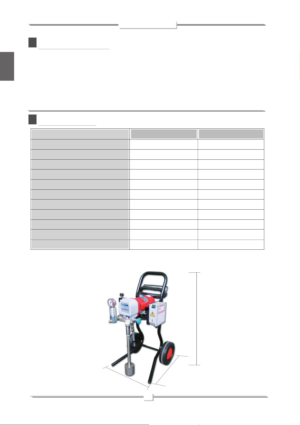
TECHNICAL DATA
SUPPLY (single-phase)*
MOTOR POWER
MAX. WORKING PRESSURE
MAX. DELIVERY
MATERIAL OUTLET
WEIGHT
sent to the gun through the flexible hose.
A mechanical device on the side of the reduction gear casing,
allows to adjust and control the pressure of the material coming
out of the pump.
When the pump reaches the set value, the motor stops and starts
again when the value decreases.
A safety valve avoiding overpressure, guarantees the total reliability
of the equipment.
TORNADO2 on trolley
220V C.A. 50H
2 kW (S2)
2,2 L/min
M16 x 1,5 (M)
210 bar
25 Kg
TORNADO2 on frame
220V C.A. 50H
2 kW (S2)
210 bar
2,2 L/min
M16 x 1,5 (M)
21 Kg
LEVEL OF THE SOUND PRESSURE
LENGTH
WIDTH
TOTAL HEIGHT
HEIGHT WITHOUT HANDLE
*Available on request with special voltages
PARTS OF THE PUMP IN CONTACT WITH THE MATERIAL Stainless Steel AISI 420B, Teflon; Aluminium
≥80dB(A)
(A) 650 mm
(B) 520 mm
(C) 965 mm
C
≥80dB(A)
(A) 500 mm
(B) 300 mm
(C) 500 mm
450 mm
A
B
2
Page 5
TORNADO 2
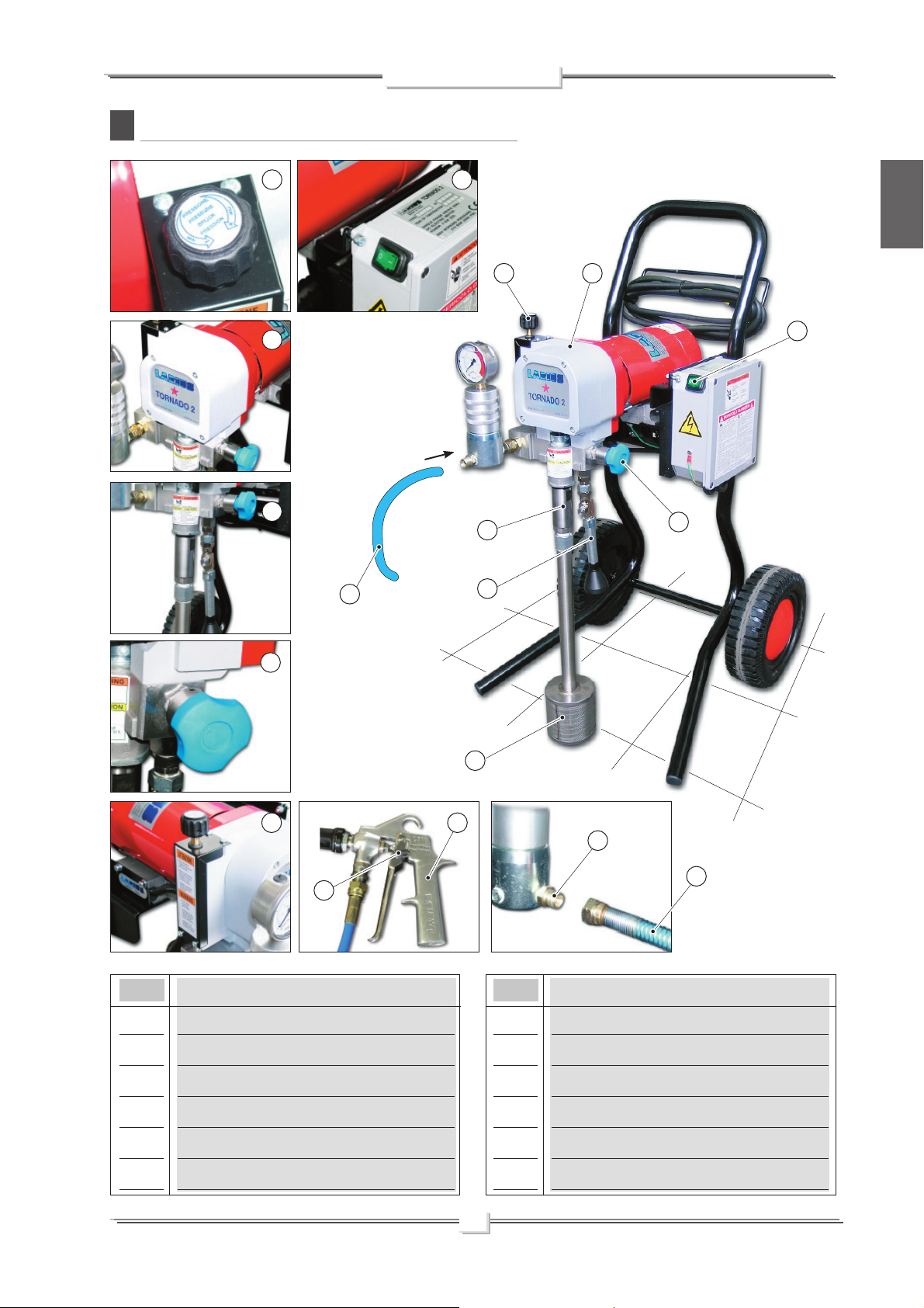
DESCRIPTION OF THE EQUIPMENT
C
2
3
4
5
1
2
4
7
3
1
8
English
POS.
1
2
3
8
9
Description
ON/OFF switch
Pressure control knob
Reduction casting
11
10
6
12
5
POS.
7
8
9
Recirculation tube
Drain valve
Pressure transmitter
Description
4
Pumping group
5
High pressure fl exible hose of compensation
6
Suction fi lter
10
Airless manual gun
11
Trigger safety clamp
12
Product fl exible pipe connection
3
Page 6
TRANSPORT
D
AND UNPACKING
TORNADO 2
English
•
The packed parts should be handled as indicated
in the symbols and markings on the outside of the
packing.
•
Before installing the equipment, ensure that the area to
be used is large enough for such purposes, is properly
lit and has a clean, smooth fl oor surface.
•
The user is responsible for the operations of unloading
and handling and should use the maximum care so as
not to damage the individual parts or injure anyone.
To perform the unloading operation, use only qualified
and trained personnel (truck and crane operators, etc.)
and also suitable hoisting equipment for the weight of
the installation or its parts.
Follow carefully all the safety rules.
The personnel must be equipped with the necessary
safety clothing.
•
The manufacturer will not be responsible for the
unloading operations and transport to the workplace
of the machine.
•
Check the packing is undamaged on receipt of the
equipment. Unpack the machine and verify if there
has been any damage due to transportation.
In case of damage, call immediately LARIUS and the
Shipping Agent. All the notices about possible damage
or anomalies must arrive timely within 8 days at least
from the date of receipt of the plant through Registered
Letter to the Shipping Agent and to LARIUS.
•
The disposal of packaging materials is a customer’s
competence and must be performed in accordance with
the regulations in force in the country where the plant is
installed and used.It is nevertheless sound practice to
recycle packaging materials in an environment-friendly
manner as much as possible.
SAFETY RULES
E
• THE EMPLOYER SHALL TRAIN ITS EMPLOYEES
ABOUT ALL THOSE RISKS STEMMING FROM ACCIDENTS, ABOUT THE USE OF SAFETY DEVICES FOR
THEIR OWN SAFETY AND ABOUT THE GENERAL
RULES FOR ACCIDENT PREVENTION IN COMPLIANCE WITH INTERNATIONAL REGULATIONS AND WITH
THE LAWS OF THE COUNTRY WHERE THE PLANT
IS USED.
THE BEHAVIOUR OF THE EMPLOYEES SHALL
STRICTLY COMPLY WITH THE ACCIDENT PREVENTION AND ALSO ENVIRONMENTAL REGULATIONS
IN FORCE IN THE COUNTRY WHERE THE PLANT
IS INSTALLED AND USED.
Read carefully and entirely the following
instructions before using the product. Please
save these instructions in a safe place.
The unauthorised tampering/replacement of
one or more parts composing the machine,
the use of accessories, tools, expendable
materials other than those recommended by
the manufacturer can be a danger of accident.
The manufacturer will be relieved from tort and criminal
liability.
• KEEP YOUR WORK PLACE CLEAN AND TIDY. DISORDER
WHERE YOU ARE WORKING CREATES A POTENTIAL
RISK OF ACCIDENTS.
• ALWAYS KEEP PROPER BALANCE AVOIDING UNUSUAL
STANCE.
• BEFORE USING THE TOOL, ENSURE THERE ARE NOT
DAMAGED PARTS AND THE MACHINE CAN WORK PROPERLY.
• ALWAYS FOLLOW THE INSTRUCTIONS ABOUT SAFETY
AND THE REGULATIONS IN FORCE.
• KEEP THOSE WHO ARE NOT RESPONSIBLE FOR THE
EQUIPMENT OUT OF THE WORK AREA.
• NEVER EXCEED THE MAXIMUM WORKING PRESSURE
INDICATED.
• NEVER POINT THE SPRAY GUN AT YOURSELVES OR AT
OTHER PEOPLE. THE CONTACT WITH THE CASTING CAN
CAUSE SERIOUS INJURIES.
• IN CASE OF INJURIES CAUSED BY THE GUN CASTING,
SEEK IMMEDIATE MEDICAL ADVICE SPECIFYING THE
TYPE OF THE PRODUCT INJECTED. NEVER UNDER-
VALUE A WOUND CAUSED BY THE INJECTION OF A
FLUID.
• ALWAYS DISCONNECT THE SUPPLY AND RELEASE THE
PRESSURE IN THE CIRCUIT BEFORE PERFORMING
ANY CHECK OR PART REPLACEMENT OF THE EQUIPMENT.
• NEVER MODIFY ANY PART IN THE EQUIPMENT. CHECK
REGULARLY THE COMPONENTS OF THE SYSTEM.
REPLACE THE PARTS DAMAGED OR WORN.
• TIGHTEN AND CHECK ALL THE FITTINGS FOR CONNECTION BETWEEN PUMP, FLEXIBLE HOSE AND SPRAY
4
Page 7

TORNADO 2
GUN BEFORE USING THE EQUIPMENT.
• ALWAYS USE THE FLEXIBLE HOSE SUPPLIED WITH
STANDARD KIT. THE USE OF ANY ACCESSORIES OR
TOOLING OTHER THAN THOSE RECOMMENDED IN
THIS MANUAL, MAY CAUSE DAMAGE OR INJURE THE
OPERATOR.
• THE FLUID CONTAINED IN THE FLEXIBLE HOSE CAN
BE VERY DANGEROUS. HANDLE THE FLEXIBLE HOSE
CAREFULLY. DO NOT PULL THE FLEXIBLE HOSE TO
MOVE THE EQUIPMENT. NEVER USE A DAMAGED OR
A REPAIRED FLEXIBLE HOSE.
The high speed of travel of the product in the
hose can create static electricity through discharges and sparks. It is suggested to earth
the equipment. The pump is earthed through
the earth cable of the supply.
The gun is earthed through the high pressure
flexible hose.
All the conductors near the work area must be earthed.
• NEVER SPRAY OVER FLAMMABLE PRODUCTS OR
SOLVENTS IN CLOSED PLACES.
Electrical safety precautions
• Check the switch is on the "OFF" position before connecting
• Never carry a plugged-in equipment.
• Disconnect the equipment before storing it and before
• Do not carry the equipment neither unplug it by pulling the
Protect the cable from heat, oil and sharp edges.
• When the tool is used outdoors, use only an extension cable
• Take care when the pumping rod is moving.
Stop the machine whenever someone is within its vicinity.
• Repairs of the electrical equipment should only be carried
the cable to the mains.
performing any maintenance operation or replacing of accessories.
electric cable.
suited for outdoor use and so marked.
Never attempt to tamper with the calibre of
instruments.
out by skilled personnel, otherwise considerabledanger to
the user may result.
English
• NEVER USE THE TOOLING IN PRESENCE OF POTEN-
TIALLY EXPLOSIVE GAS.
Always check the product is compatible with
the materials composing the equipment (pump,
spray gun, flexible hose and accessories) with
which it can come into contact. Never use paints
or solvents containing halogen hydrocarbons
(as the methylene chloride).
If these products come into contact with aluminium parts can
provoke dangerous chemical reactions with risk of corrosion
and explosion.
IF THE PRODUCT TO BE USED IS TOXIC, AVOID INHALATION AND CONTACT BY USING PROTECTION GLOVES,
GOGGLES AND PROPER FACE SHIELDS.
SETTING-UP
F
CONNECTION OF THE FLEXIBLE HOSE TO THE GUN
• Connect the high pressure fl exible hose push-button
the pump and to the gun
(the use of two wrenches is suggested).
NEVER use sealants on fi ttings’ threads.
(F2)
ensuring to tighten the fi ttings
F2
F1
(F1)
to
TAKE PROPER SAFETY MEASURES FOR THE PROTECTION OF HEARING IN CASE OF WORK NEAR THE
PLANT.
F2
5
Page 8
English
Voltaggio
TORNADO 2
It is ADVISED to mount a high pressure manometer at the
pump outlet (see on page “Accessories”) to read the product
pressure.
• It is recommended to use the hose provided with the standard
kit (ref.18036).
NEVER use a damaged or a repaired fl exible hose.
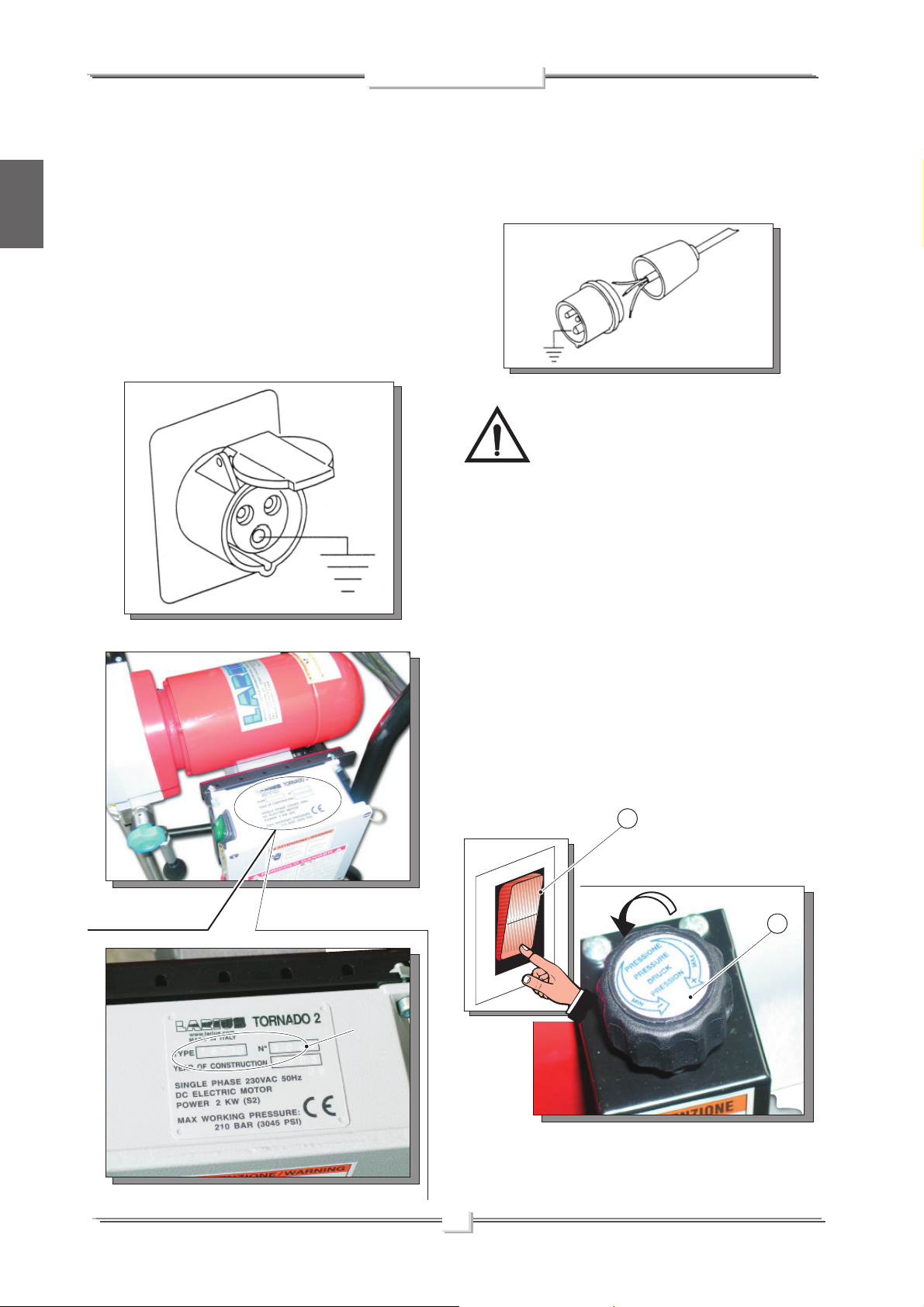
CHECK ON POWER SUPPLY
• Check the plant is earthed.
• Check the mains voltage corresponds to the equipment’s
rating.
• The supply cable is provided without plug.
Use a plug which guarantees the plant earthing.
Only a technician or a skilled person should perform the
connection of the plug to the electric cable.
Should anyone use an extension cable between
the tooling and the socket, it must have the same
characteristics as the cable supplied (minimum
diameter of the wire 2.5 mm
2
) with a maximum
length of 50 mt. Higher lengths and lower diameters can
provoke excessive voltage falls and also an anomalous
working of the equipment.
Voltaggio
CONNECTION OF THE TOOLING TO THE POWER SUPPLY
• Check the switch (F3) is on the "OFF"(0) position before
connecting the cable to the mains.
• Place the pressure control knob (F4) on the “MIN” position
(turn counterclockwise).
F3
ON (I)
F4
OFF (0)OFF (0)
6
Page 9
TORNADO 2
WASHING OF THE NEW EQUIPMENT
• The equipment has already been adjusted at our factory with
light mineral oil left inside the pumping group as protection.
Therefore, wash with diluent before sucking the product.
• Remove the suction pipe and take away the solvent tank.
English
• Lift the suction pipe and dip it into the solvent tank.
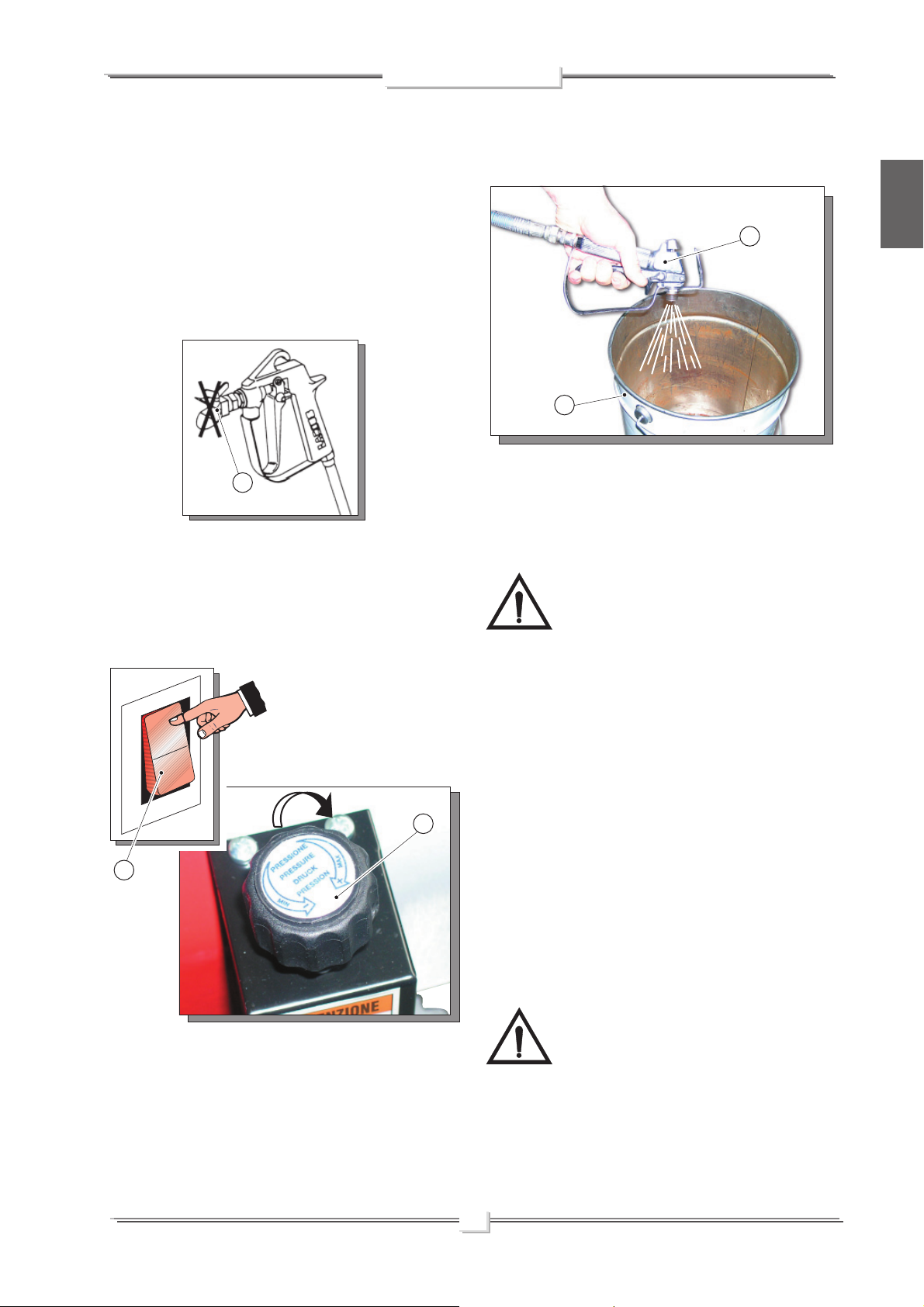
• Ensure the gun is without nozzle (F5).
F5
• Press the switch (F6) of the equipment ON (I).
• Turn clockwise the pressure control knob (F7) so as the
machine works at idle speed.
F8
F9
• Point the gun at the solvent tank and press the trigger so as
to recover the residual solvent.
• As the pump idles, press the OFF (0) switch to stop the
tooling.
Absolutely avoid to spray solvents indoors. In
addition, it is recommended to keep away from
the pump in order to avoid the contact between
the solvent fumes and the electric motor.
• Now the machine is ready. Should you use water paints,
besides the solvent wash, a wash with soapy and then clean
water is suggested.
ON (I)
OFF (0)
F7
F6
• Point the gun (F8) at a container (F9) keeping the trigger
pressed ( so as to drain the oil inside) till a clean solvent
comes out. Now, release the trigger.
• Insert the gun trigger lock and assemble the nozzle.
PREPARATION OF THE PAINT
• Make sure the product is suitable to be used with a spray
gun.
• Mix and fi lter the product before using it. For fi ltration, use
CLOSE-MESH (ref. 214) and LARGE-MESH (ref.215) LA-
RIUS METEX braids.
Make sure the product to be used is compatible
with the materials employed for manufacturing the
equipment (stainless steel and aluminium). Because
of that, please contact the supplier of the product
Never use products containing halogen hydrocarbons (as methylene chloride). If these products come into contact with aluminium
parts of the equipment, can provoke dangerous chemical reactions
with risk of explosion.
.
7
Page 10
WORKING
G
TORNADO 2
English
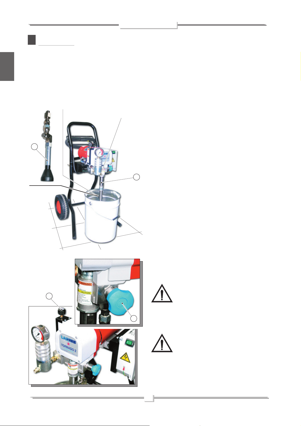
START OF THE PAINTING OPERATIONS
• Use the tooling after performing all the SETTING UP operations above described.
• Dip the suction pipe (G1) into the product tank.
Delivery pipe connection
G4
G1
• Open the safety- relief valve (G2) (turn clockwise so as the
pin slides on the cam track).
• Press the switch ON (I) of the equipment and turn a little the
pressure control knob (G3) clockwise, so as the machine
works at the idle speed.
• Make sure the product recycles from the return tube (G4).
• Close the drain valve (turn clockwise till the valve has relea-
sed).
• Now the machine carries on sucking the product till the fl exible
hose is full, up to the gun. Then it will stop automatically.
SPRAY ADJUSTMENT
• Slowly turn clockwise the pressure control knob to reach the
pressure value in order to ensure a good atomization of the
product.
G3
G2
• An irregular and marked spray on the sides indicates a low
working pressure. On the contrary, a too high pressure causes
a high fog (“overspray”) and waste of product.
• In order to avoid overthickness of paint, let the gun advance
sideways (right-left) when spraying.
• Always paint with regular parallel bands coats.
• Keep a safety and constant distance between the gun and the
support to be painted and also keep yourselves perpendicular
to it.
NEVER point the spray gun at yourselves or at
other people. The contact with the casting can
cause serious injuries.
In case of injuries caused by the gun casting,
seek immediate medical advice specifying the type of the
product injected.
The drain valve is a safety valve too. When
working at the maximum pressure available,
releasing the gun trigger sudden increases of
pressure can occur. In this case, the drain valve
opens automatically eliminating part of the product from the
recirculating tube. Then it closes so as to go back to the first
working conditions.
8
Page 11

TORNADO 2
CLEANING AT THE END
H
OF THE WORK
• Reduce pressure to the minimum (turn counterclockwise the
pressure control knob (H1)).
• Press the switch (H2) placed on the box of the electric motor,
to stop the equipment.
H2
ON (I)
OFF (0)OFF (0)
H1
Follow the washing procedure before using again
the equipment.
I
ROUTINE MAINTENANCE
CHECK ON THE PACKING NUT
Daily check the packing nut is tight in order to avoid wastes but
not excessively to prevent the piston from seizing and the
gaskets from wearing.
• For tightening, use the wrench (I1) supplied (ref. 11503).
ALWAYS DISCONNECT THE POWER SUPPLY
AND RELEASE THE PRESSURE IN THE PUM-
PING GROUP (open the drain valve) BEFORE
TIGHTENING THE PACKING NUT.
English
• Use the lubricant (I2) supplied (rif. 16325) to allow an easy
sliding of the piston inside the gasket group.
• Open the safety valve to release the pressure in the circuit.
• Lift the suction pipe and replace the product tank with that
of the solvent (ensure it is compatible with the product being
used).
• Unscrew the gun nozzle (do not forget to clean it with sol-
vent).
• Press the switch (H2) ON (I) and turn a little the pressure
control knob (H1) clockwise so as the machine works till
the motor starts.
• Make sure the solvent recycles the washing fl uid from the
return tube.
• Close the safety valve.
• Point the gun at the product tank and, keeping the trigger
pressed, release the remaining product till a clean solvent
comes out. Now, release the trigger.
• Lift again the suction pipe and remove the solvent tank.
• Now point the gun at the solvent tank and press the trigger
so as to recover the residual solvent.
Daily top up the packing nut.
I2
• As the pump starts idling, press the switch OFF (0) to
stop the equipment.
• In case of long storage, we recommend you to suck and
to leave light mineral oil inside the pumping group and the
fl exible hose.
Oil ring
I1
9
Page 12

TORNADO 2
L PROBLEMS AND SOLUTIONS
English
Problem
• The equipment does not start
• The equipment does not suck the
product
Cause
• Lack of voltage;
• Considerable drops in mains voltage;
• On/Off switch disconnected;
• Breakdown of pressure transmitter;
•
Breakdown of motor electric control box;
• The line of material coming out of the
pump is already under pressure;
• The product is solidified inside the
pump;
• Suction filter clogged;
• Suction ilter too fine;
• The equipment sucks air;
• Check the correct connection to the
power supply;
• Check the extension cable;
• Ensure the On/Off switch is on the
“on” position and turn clockwise the
pressure control knob;
• Verify and replace it, if necessary;
• Verify and replace it, if necessary;
• Open the drain valve to release
pressure in the circuit;
• Open the drain valve to release
pressure in the circuit and stop the
machine. Disassemble the pumping
group and the pressure transmitter
and clean;
• Clean or replace it;
• Replace it with a larger-mesh filter
(with very dense products, remove
the filter);
• Check the suction pipe;
Solution
• The equipment sucks but does not
reach the pressure desired
• When pressing the trigger, the
pressure lowers considerably
• The pressure is normal but the
product is not atomized
• The atomization is imperfect
•
When releasing the trigger of the
gun, the equipment does not stop
(the motor runs slowly and the
piston rod keeps on going up and
down)
• Lack of product;
• The equipment sucks air;
• The drain valve is open;
• The gaskets of the pumping group are
worn;
• Suction or delivery val ve dirty;
• Nozzle too big or worn;
• The product is too dense;
• The filter of the gun-butt is too fine;
• The nozzle is partially clogged;
• The product is too dense;
• The filter of the gun-butt is too fine;
• The nozzle is worn;
• The gaskets of the pumping group are
worn;
• Suction or delivery val ve dirty;
• Drain valve defective;
• Add the product;
• Check the suction pipe;
• Close the drain valve;
• Replace the gaskets;
• Disassemble the pumping group;
• Replace it with a smaller one;
• Dilute the product, if possible;
• Replace it with a larger-mesh filter;
• Clean or replace it;
• Dilute the product, if possible;
• Replace it with a larger-mesh filter;
• Replace it;
• Replace the gaskets;
• Disassemble the pumping group and
clean;
• Verify and replace it, if necessary;
Always close the air compressed supply and unload the plant pressure before performing any check or replacement of pump parts (see "correct procedure of decompression").
10
Page 13

TORNADO 2
M CORRECT PROCEDURE OF DECOMPRESSION
• Insert the gun clamp (M1).
• Move the switch (M2) to the OFF (0) position to stop the
equipment.
M1
• Disconnect the power supply cable (M3).
English
M2
ON (I)
OFF (0)OFF (0)
M3
• Release the gun clamp (M4), point the gun at the tank of the
product and press the trigger to release pressure. At the end
of the operation, insert the gun clamp.
• Open the drain valve (M5) to release the residual pressure
always clockwise.
WARNING:
If the equipment is still under pressure after performing the operations above described
because of the nozzle or the flexible hose clogged, proceed as follows:
• Loosen very slowly the gun nozzle.
• Release the clamp.
• Point the gun at the container of the product and press the trigger to release
pressure.
• Loosen very slowly the fi tting of connection from the fl exible hose to the gun.
• Clean or replace the fl exible hose and the nozzle.
M4
M5
11
Page 14

TORNADO 2
N REPLACEMENT OF THE PUMPING GROUP’S GASKETS
English
• Carry out this operation after cleaning the tooling.
Always disconnect the power supply and release
pressure before going on with the operations (fol-
low the “correct procedure of decompression).
• Disconnect the pumping group by unscrewing the two fastening
screws.
• Using a screwdriver, turn the motor till the piston rod is on
its stroke lowest point.
• Extract the pumping group from the housing paying attention
to the dowel pins.
• Unscrew the rigid suction pipe from the pumping group by
• Unscrew the upper packing nut;
• Unscrew the suction valve and clean and/or replace its parts,
• Extract the piston rod from the bottom;
• Disassemble the piston rod and replace the gaskets group
• If necessary, remove the upper gaskets for their replace-
• See the exploded view of the pumping group for the correct
loosening the locknut;
if necessary;
if worn;
ment;
assembly.
Dowel pins
WARNING PLATE
O
Apparecchi per verniciatura
UTILIZZARE GRUPPI ELETTROGENI
CON ALTERNATORE ASINCRONO
http: www.larius.com
ATTENZIONE
Clamping screws
Lock nut
Paint spraying units
WARNING
USE POWER UNITS WITH
ASYNCHRONOUS ALTERNATOR
e-mail larius@larius.com
12
Page 15

CLEANING AND/OR RE-
P
TORNADO 2
PLACEMENT OF THE PRESSURE TRANSMITTER
CHECK ON THE PRESSURE TRANSMITTER
Before evaluating if the cause of the malfunction is due to the
pressure transmitter or to the electric control box, proceed as
follow:
• Check the correct connection to the power supply.
• Ensure the ON/OFF switch (P1) is on the ON (I) position.
• Turn a little the pressure control knob (P2) clockwise till the
electric motor starts.
• In case, after these checks, the tooling does not start, verify
the pressure transmitter.
• Make sure the equipment does not suck materials (remove
the product tank).
• Open the drain valve (P3).
• Disassemble the pumping group as shown on the previous
chapter.
• Remove the pressure sensor from its housing and chek if
the pin can move. If necessary, clean thoroughly.
• Check the seals (O-ring and tefl on ring): if worn or "pinched",
replace them.
• Disassemble the supporting block and check the microswitch
operates properly by using a tester. If damaged, replace it.
• Reassemble the whole unit centering the block with the
fastening screws.
• Reassemble the whole unit and start again the machine
following the procedure indicating.
• If the machine does not start, check the electrical connections
and the motor electric control box: if damaged, replace it.
English
P1
P2
ON (I)
OFF (0)
Pressure
sensor
Pressure pin
P3
13
Page 16

English
TORNADO 2
Q COMPLETE PRESSURE CONTROL DEVICE
REF. 16350
WARNING: always indicate code and quantity for each part required.
11
27
11
13
29
12
30
23
28
11
11
10
9
8
7
6
5
4
26
3
18
25
2
1
24
14
22
19
20
17
18
15
15
16
14
Page 17

TORNADO 2
Pos. Pos.
1
2
3
4
5
6
7
8
9
10
11
12
13
14
Co de Description Co de Description
16336
16335
11955
16334
9287
16333
16331
16332
4077
96090
96028
16037
16042
16280
Elastic ring
Washer
Gasket
Pin
O-ring
Antiextrusion ring
Sensor
Gas-ring
O-ring
Ball
Screws
Gasket
Cover
Cable fastener
16
17
18
19
20
21
22
23
24
25
26
27
28
29
16307
22059
16310
16313
16311
16306
16304
81017
4060
16303
16309
16315
16301
95210
Bush
Dowel
Screws
Microswitch
Support box
Control rod
Quill
Elastic ring
Ball
Spring
Pin
Adjusting pin
Knob
Dowel
English
15
16312
Screws
30
16308
Label
15
Page 18

English
TORNADO 2
COMPLETE PUMPING GROUP TORNADO2 REF.16100
R
WARNING: always indicate code and quantity for each part required.
1
2
3
5
6
7
8
9
13
10
11
12
4
4
8
14
15
16
Pos.
1
*
2
**
3
4
5
6
7
8
9
10
11**
12
*
13
**
14
15
16**
Co de Description
16109
16105
96205
16033
16101
33007
33006
16111
16110
91010
16130
16113
16115
16128
16127
16126
Packing nut
Complete upper seals
Dowel
Assembly pins
Pumping case
Screws
Piston rod
Screws
Piston rod
Elastic pin
Ball
Nut
Complete lower seals
Union
Lock nut
O-ring
21
17
18
19
20
22
17
18
19**
20**
21
22
* Complete gasket kit cod. 16555
** Pumping maintenance kit cod. 40116
16112
98466
16120
16121
16129
16122
Pumping cylinder
Ball guide
Ball
O-ring
Foot valve
Pin
16
Page 19

TORNADO 2
Steel female ring
cod. 16106
White cod. 16124
Red cod. 16104
Leather cod.16155
Red cod. 16104
White cod. 16124
Steel male ring
cod. 16108
System of assemblage
cod.
16132
English
cod.
16105
Upper seals
Steel male ring
cod. 16116
White cod. 16136
Red cod. 16114
White cod. 16136
Red cod. 16114
Steel female ring
cod. 16118
cod.
16133
17
cod.
16115
Lower seals
Page 20

TORNADO 2
S
FILTER GROUP
WARNING: always indicate code and quantity for each part required.
English
Manometer 0-400 bar code 33008
1
2
3B
3A
3C
4
Pos.
1
5
6
8
8
8
2
3A
3B
3C
4
5
6
7
8
Co de Description
16201
96202
16205
16204
16203
16202
96203
96204
96206
96205
Filter tank
Spring
Standard sieve
Standard sieve 100
Standard sieve 200
Sieve support
Gasket
Filter base
Union
Dowel
18
Page 21

TORNADO 2
T RECIRCULATING-SAFETY VALVE GROUP REF. 16400
WARNING: always indicate code and quantity for each part required.
5
4
3
2
English
9
8
7
6
10
1
Pos.
1
2
3
4
5
6
7
8
9
10
Co de Description
4033
16415
53007/3
16419
16420
16410
46409
16408
16405
90018
O-ring
Valve housing
O-ring
Antiextrusion ring
Material rod
Spring
Bush
Dowel
Knob
Dowel
19
Page 22

U DRIVE ASSEMBLY
TORNADO 2
English
26
1B
10
11
12
14
25
13
22
21
15
23
16
23
24
21
20
19
18
1A
9
17
8
6
3
5
4
2
5
7
2
4
1
20
Page 23

TORNADO 2
Pos. Pos.
1
1A
1B
2
3
4
5
6
7
8
9
Co de Description Co de Description
16724
16723
37485
16012
16016
91915
37147
16021
16015
16020
16022
Complete electric motor 110V Tornado2
Complete electric motor - Tornado2
Electronic box - Tornado
Bearing
Bearing
Thrust-bearing ball
Pin
Thrust-bearing
Driving gear
Gear
Thrust-bearing
13
14
15
16
17
18
19
20
21
22
23
16026
16028
16019
8029
16029
95623
16027
16030
81032
16031
16036
Pin
Pad
Bearing
Screw
Gearcase
Screw
Bushing
Closing bracket
Screws
Cover
Screw
English
10
11
12
16024
16025
16040
Bearing
Connecting rod
Bush
24B
25
26
16045
16023
18053
Tornado label
Dowel
Motor cover
21
Page 24

English
TORNADO 2
V ELECTRIC MOTOR
WARNING: Always indicate code and quantity for each part required.
DISCONNECT THE POWER SUPPLY BEFORE
CHECKING OR REPLACING THE BRUSHES
• Periodically check on the wear of the pinion (at least every
1000 working hours).
• Periodically check the perfect connection among all the
electrical components (at least every 200 working hours).
• The length of the brush contact must be higher than 9 mm
to guarantee a good working of the rotary group.
9 mm*
Pos.
1
2
2
Co de Description
16727
16728
Brush
Brush holder plug
1
*Minimum lenght of the brush
22
Page 25

W COMPLETE FRAME
TORNADO 2
WARNING: always indicate code and quantity for each part required.
TROLLEY MOUNTED MODEL
2
11
8
7
10
12
9
13
English
14
1
5
4
Co de Description
16270
1
2
3
4
5
6
7
16272
16271
16792
34005
34004
37238
16060
6
Complete trolley
Trolley frame
Handle
Feet
Split pin
Washer
Wheel
Bracket
3
Pos.
8
9
10
11
12
13
14
Co de DescriptionPos.
16240
8042
84007
31104
54003
91026
18043
Screw
Nut
Split pin
Screw
Washer
Nut
Electric box plate
23
Page 26

CHASSIS MOUNTED MODEL
TORNADO 2
English
7
9
7
1
5
2
10
6
Z ACCESSORIES
Pos.
1
4
3
1
2
3
4
5
6
7
9
10
Co de Description
Complete trolley
16/34
16240
18050
16232
16233
34011
16231
16235
8042
Screw
Screw
Bracket
Right frame
Left frame
Feet
Shaped handle
Knob
Nut
WARNING: always indicate code and quantity for each part required.
TROLLEY MOUNTED MODEL
1
2
Pos.
3
4
Co de Description
1
2
3
16602
16601
37216
Pipe fi tting
Suction pipe
Filter
24
4
37600
Complete fi tting
Page 27

CHASSIS MOUNTED MODEL
TORNADO 2
English
8
Pos.
4
2
1
3
Co de Description Pos.
5
7
6
Co de Description
1
2
3
4
5
16802
18351
18352
18353
18608
Filter
Dispersion bell
Breaker fl ux
Bell pipe
Pipe fi tting with spring
6
7
8
22028
16058
18026
Female extension 3/8" - male 1/4"
Pipe fi tting
Delivery compensation hose length
15 mt
25
Page 28

English
TORNADO 2
Code 11250: AT 250 1/4"
Code 11200: AT 250 M16x1,5
Code 85014: FILTER 40 MESH - Code 85012: FILTER 20 MESH
Code 37215: FILTER 40 MESH inox - Code 37216: FILTER 20 MESH inox
Code 270: FILTER 100 MESH
Code 271: FILTER 60 MESH
Code 16205: FILTRO 60 MESH
Code 16204: FILTRO 100 MESH
Code16203: FILTRO 200 MESH
PISTON GUNSTOCK FILTERS
Code 11039: Green (30M) - Code 11038: White (60M)
Code 11037: Yellow (100M) - Code 11019: Red (200M)
MX 750
MX 1000 E
MX 1100 E
Code 217550: MX 750 - Code 217560: MX 1000 E - Code 217570: MX 1100 E
Code 18026: 1/4" - 15 mt
ANTIPULSATION HOSE
MANUAL GUN LX-T
Code 14310: NOZZLE 4 mm
Code 14311: NOZZLE 6 mm
Code 14312: NOZZLE 8 mm
26
Page 29

FAST-CLEAN
TORNADO 2
FAST-CLEAN TIP
07-20
07-40
09-20
09-40
11-20
11-40
13-20
13-40
13-60
15-20
15-40
15-60
17-20
17-40
17-60
19-20
19-40
Nozzles code
19-60
21-20
21-40
21-60
23-20
23-40
23-60
25-20
25-40
25-60
27-20
27-40
27-60
27-80
29-20
29-40
29-60
29-80
31-40
31-60
31-80
33-40
33-60
33-80
39-40
39-60
39-80
43-40
43-60
43-80
51-40
51-60
51-80
English
SUPER FAST-CLEAN
Code 303: GASKET
Code 300: FAST-CLEAN base UE 11/16x16
SUPER FAST-CLEAN TIP
SFC07-20
SFC07-40
SFC09-20
SFC09-40
SFC11-20
SFC11-40
SFC13-20
SFC13-40
SFC13-60
SFC15-20
SFC15-40
SFC15-60
SFC17-20
SFC17-40
SFC17-60
SFC19-20
SFC19-40
Nozzles code
SFC19-60
SFC21-20
SFC21-40
SFC21-60
SFC23-20
SFC23-40
SFC23-60
SFC25-20
SFC25-40
SFC25-60
SFC27-20
SFC27-40
SFC27-60
SFC27-80
SFC29-20
SFC29-40
SFC29-60
SFC29-80
SFC31-40
SFC31-60
SFC31-80
SFC33-40
SFC33-60
SFC33-80
SFC39-40
SFC39-60
SFC39-80
SFC43-40
SFC43-60
SFC43-80
SFC51-40
SFC51-60
SFC51-80
Code 18280: GASKET
Code 18270: SUPER FAST-CLEAN base UE 11/16x16
27
Page 30

English
TORNADO 2
PLA 1/4”
+ FAST-CLEAN REVERSIBLE
TIP INCLUDED
Code 11420-11425-11430: cm 130-180-240
PLA M16x1,5
+ FAST-CLEAN REVERSIBLE TIP INCLUDED
Code 11421-11426-11431: cm 130-180-240
PAINT ROLLER TELESCOPIC
Code 16988: Roller cover for
rough surfaces
Code 16997: Roller cover for
smooth surfaces
Code 16998: Roller cover for
very smooth surfaces
Code 16999: Roller cover for
semi-rough surface
Code 16780: Extension 120 - 195 cm
28
Page 31

TORNADO2 VERSIONS
Ref. 16720 Ref. 16730
Due to a constant product improvement programme, the factory reserves the right to modify
technical details mentioned in this manual without prior notice.
Page 32

AIRLESS PISTON PUMPS
STORM 4 Ref. 37400 STORM 4 Ref. 37520
EXCALIBUR Ref. 18600 EXCALIBUR Ref. 18601
STORM 5 Ref. 38400
MANUFACTURER:
23801 CALOLZIOCORTE - LECCO - ITALY - Via Stoppani, 21
Tel. (39) 0341/62.11.52 - Fax (39) 0341/62.12.43
E-mail: larius@larius.com - Internet http://www.larius.com
DIRECT LINE
CUSTOMERS TECHNICAL SERVICE
Tel. (39) 0341/621256
Fax (39) 0341/621234
 Loading...