

ITALIANO
Ediz. 006 - 12/2017
www.larius.eu
INSTRUCTION MANUAL
Sirio
27:1
32:1

SIRIO
Ediz. 006 - 12/2017
www.larius.eu
2
Due to a constant product improvement programme, the factory reserves the right to modify technical
details mentioned in this manual without prior notice.
This manual is to be considered as an English language translation of the original manual in Italian. The
manufacturer shall bear no responsibility for any damages or inconveniences that may arise due to the
incorrect translation of the instructions contained within the original manual in Italian.
SIRIO
Ediz. 006 - 12/2017
www.larius.eu
3
SPARE PARTS
COMPLETE PNEUMATIC MOTOR .................... p.35
PNEUMATIC REGULATOR UNIT ASSEMBLY. ... p.37
PUMPING 155 CC (32:1) ..................................... p.38
PUMPING 180 CC (27:1) ..................................... p.39
FILTER ASSEMBLY ............................................p.40
STANDARD COMPLETE TROLLEY .................... p.41
PAINT SUCTION SYSTEM ................................. P. 42
PUMPING UNIT COUPLING KIT ........................ p.43
ACCESSORIES .................................................. p.44
INDEX ................................................................. P. 3
WARNINGS ........................................................P. 5
WORKING PRINCIPLE ....................................... p. 6
TECHNICAL DATA ............................................. p. 6
DESCRIPTION OF THE EQUIPMENT ............... p. 8
TRANSPORT AND UNPACKING ....................... p.10
SAFETY RULES ................................................. p.11
SETTING-UP ...................................................... p.12
WORKING ......................................................... p.14
CLEANING AT THE END OF THE WORK .......... p.14
ROUTINE MAINTENANCE ................................. p.15
DISASSEMBLY AND REASSEMBLY
OF THE PUMPING UNIT .................................... p.16
RIPRISTINO MANUALE DEL MOTORE
PNEUMATICO ................................................... p.24
DISASSEMBLY AND REASSEMBLY
OF THE PNEUMATIC MOTOR ........................... p.25
PROBLEMS AND SOLUTION ............................ p.33
Q
R
S
N
O
P
A
B
C
D
E
F
G
H
J
K
L
M
I
T
U
V
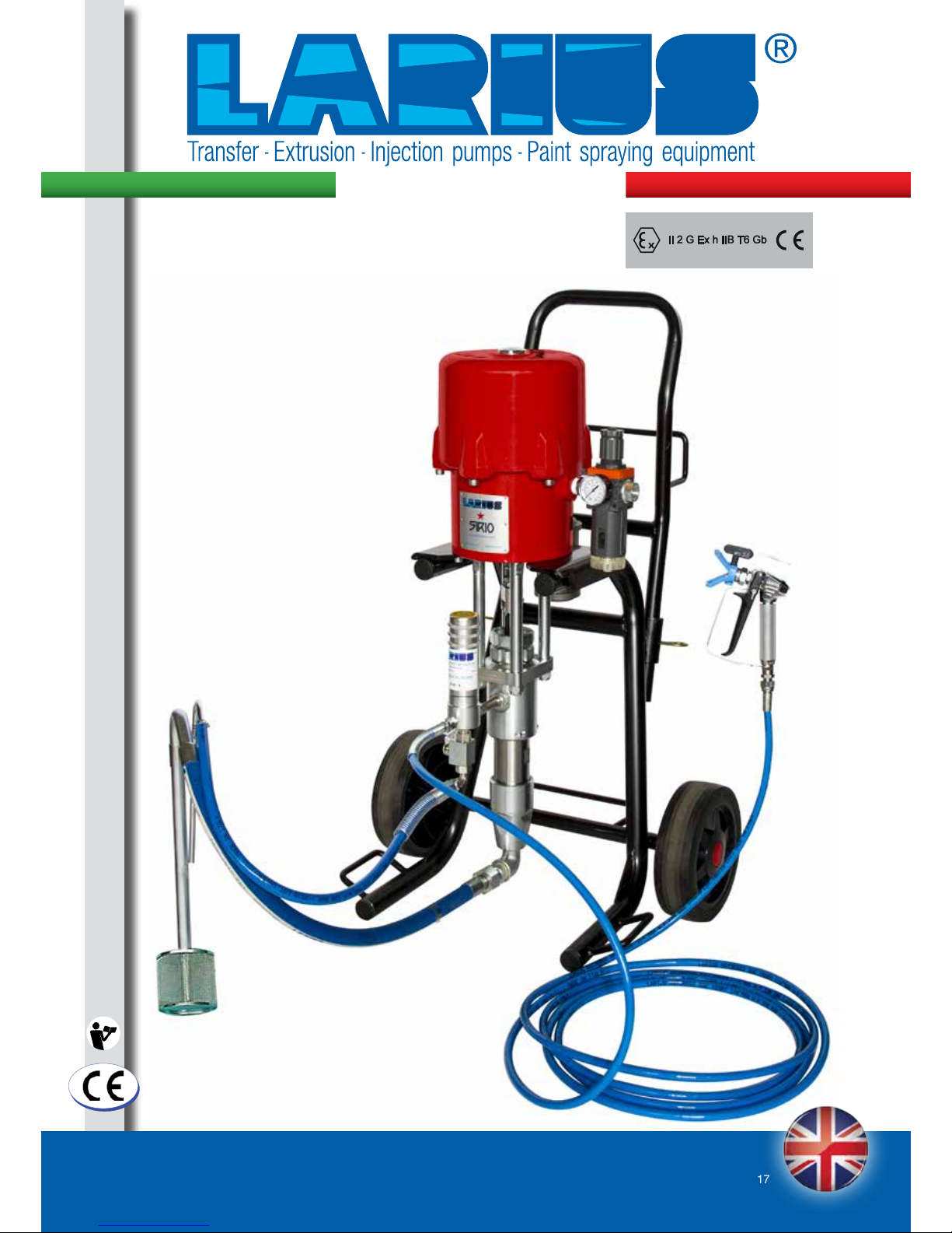
AIRLESS PNEUMATIC PUMPS FOR SPRAY PAINTING
WE ADVISE THE USE OF THIS EQUIPMENT ONLY BY PROFESSIONAL OPERATORS.
ONLY USE THIS MACHINE FOR USAGE SPECIFICALLY MENTIONED IN THIS MANUAL.
Thank you for choosing a LARIUS S.R.L. product. As well as the product
purchased, you will receive a range of support services
enabling you to achieve the results desired, quickly and professionally.
SIRIO
Ediz. 006 - 12/2017
www.larius.eu
4
White page
intentionally
SIRIO
Ediz. 006 - 12/2017
www.larius.eu
5
Read this operator’s manual carefully before using the equipment.
An improper use of this machine can cause injuries to people or things.
Do not use this machine when under the influence of drugs or alcohol.
Do not modify the equipment under any circumstances.
Use products and solvents that are compatible with the various parts of the equipment, and read the manufacturer’s warnings
carefully.
See the Technical Details for the equipment given in the Manual.
Check the equipment for worn parts once a day. If any worn parts are found, replace them using ONLY original spare parts.
Keep children and animals away from work area.
Comply with all safety standards.
It indicates an accident risk or serious damage to equipment if this warning is not followed.
It indicates important recommendations about disposal and recycling process of products in accordance with the environmental
regulations.
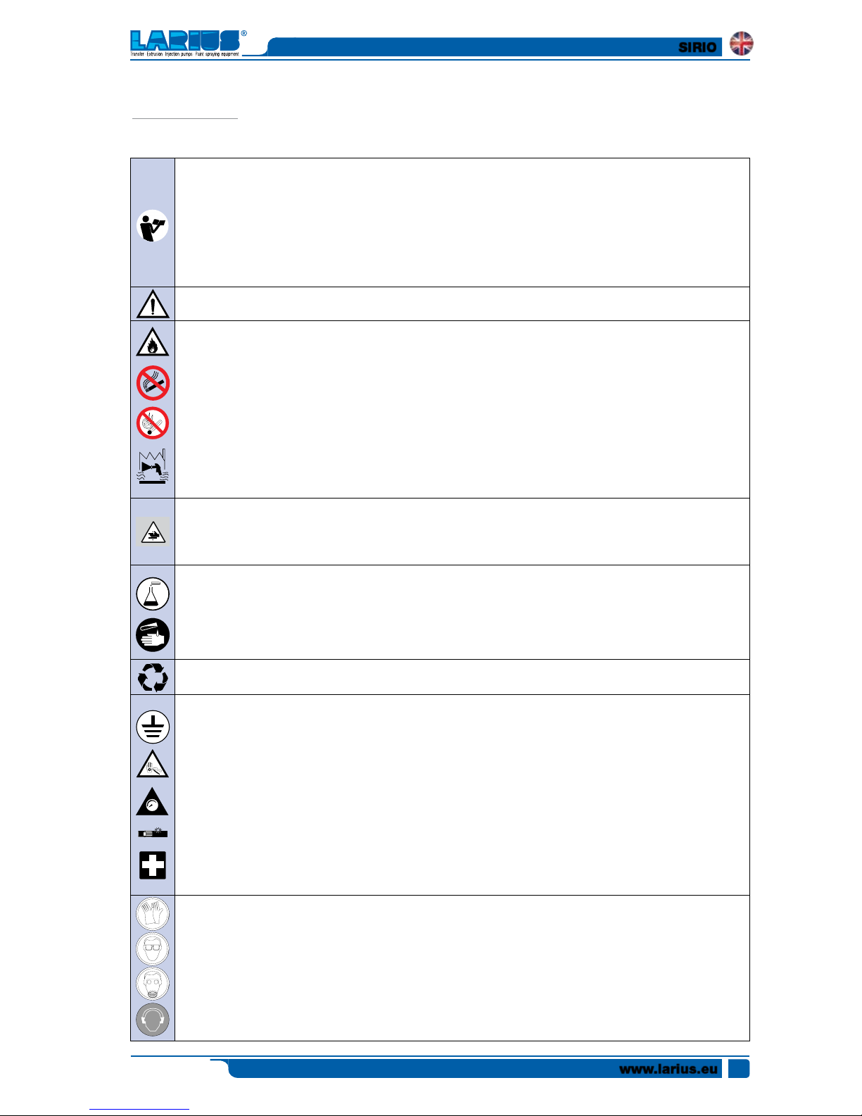
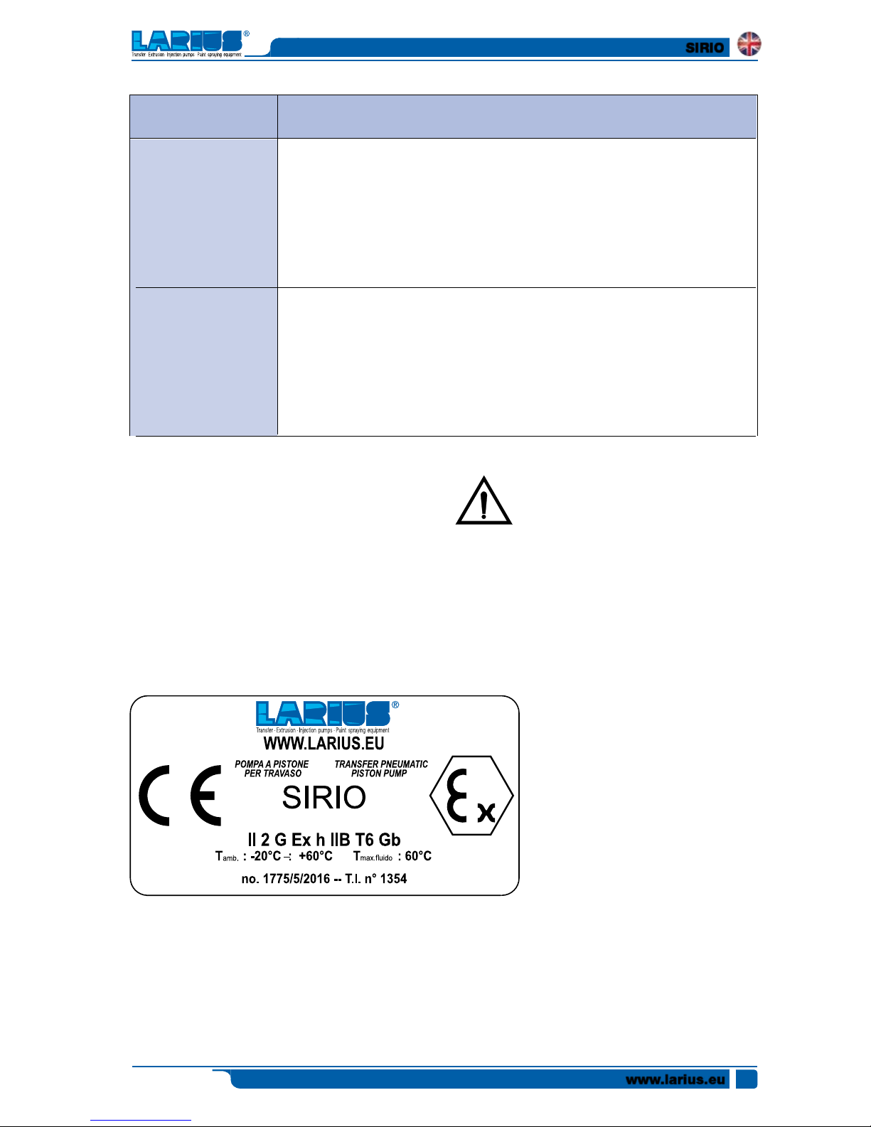
WARNINGS
The table below provides the meaning of the symbols used in this manual in relation to using, earthing,
operating, maintaining, and repairing of this equipment.
It indicates wound and finger squashing risk due to movable parts in the equipment.
Tenersi lontano dalle parti in movimento.
Do not use the equipment without the proper protection.
Before any inspection or maintenance of the equipment, carry out the decompression procedure explained in this manual, and
prevent any risk of the equipment starting unexpectedly.
Report any risk of chemical reaction or explosion if this warning has not been given.
There is a risk of injury or serious lesion related to contact with the jet from the spray gun. If this should occur, IMMEDIATELY
contact a doctor, indicating the type of product injected.
Do not spray before the guard has been placed over the nozzle and the trigger on the spray gun.
Do not put your fingers in the spray gun nozzle.
Once work has been completed, before carrying out any maintenance, complete the decompression procedure explained in
this manual.
This symbol signals the presence of a terminal with a grounding cable.
Use ONLY three-wire extensions and electrical outlets with grounding connections.
Before beginning work, make sure the electrical system is equipped with a grounding connection and that it complies with the safety
regulations.
High-pressure fluid from gun, hose leaks, or ruptured components will pierce skin.
To help prevent injection, always:
- Engage trigger lock when not spraying.
- Do not put your hand over the spray tip. Do not stop or deflect leaks with your hand, body or other.
- Do not point gun at anyone or at any part of the body.
- Never spray without tip guard.
- Ensure the trigger is locked at the end of spraying procedure.
- Do pressure relief at the end of spraying procedure and before any service operation.
- NEVER use components whose operating pressure is below the Maximum Working Pressure.
- Never allow children use this unit.
- Pay close attention to the possible recoil during gun triggering.
If high pressure fluid pierces your skin, the injury might look like “just a cut”, but it is a serious wound! Get immediate medical attention.
It is obligatory to wear suitable clothing as gloves, goggles and face shield.
Wear clothing that complies with the safety standards in force in the country in which the equipment is used.
Do not wear bracelets, earrings, rings, chains, or anything else that may hinder the operator’s work.
Do not wear clothing with wide sleeves, scarves, ties, or any other piece of clothing that could get tangled up in moving parts of
the equipment during the work, inspection, or maintenance cycles.
FIRE AND EXPLOSION HAZARD
Solvent and paint fumes in working area can ignite or explode.
To help prevent fire and explosion:
• Use equipment ONLY in well ventilated area.
• Eliminate all ignition sources, such as pilot lights, cigarettes and plastic drop cloths (potential static arc).
• Ground equipment and conductive objects.
• Use only grounded airless conductive hoses.
• Do not use trichloroethane, methylene chloride, other halogenated hydrocarbon solvents or fluids containing such
solvents in pressurized aluminium equipment. Such use can cause serious chemical reaction and explosion.
• Never clean when the electrostatic parts of the gun are ON. Turn on the electrostatic parts of the gun only after having
removed any solvent from the circuit.
• Use cleaning solvents with a flash point as high as possible, preferably higher than ambient temperature
If electrical shocks or discharges are encountered, immediately stop the operation of the equipment.
Keep a fire extinguisher at hand close to the working area.
0
SIRIO
Ediz. 006 - 12/2017
www.larius.eu
6
A
B
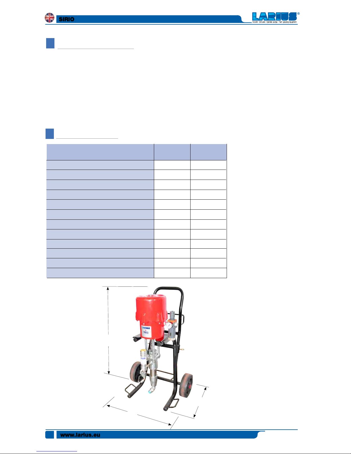
Sirio pumps are pneumatic pumps for high pressure painting
without the use of compressed air (AIRLESS). The stainless steel
version is particularly suitable for use with water-based paints.
The Sirio pump is essentially comprised of an air motor and
a structure known as the “Material Pumping Unit”, or simply
the “Pumping Unit”.
In the pneumatic motor, compressed air causes the vertical
reciprocating movement of the motor piston; this movement
is transmitted through a connecting rod to the material pum-
ping piston.
This allows for the material to be aspirated and pushed towards
the outlet. The unit comes complete with a transportation
trolley, a high-pressure material filter, an air supply regulator
for the pump, a material suction tube (complete with filter)
and a recirculation tube.
The ratio (27:1-30:1-32:1-45:1) means that the outlet pressure
of material is (27-30-32-45) times higher than the pump feed
air pressure.
TECHNICAL DATA
27:1
3-7 bar
189 bar
1/2" GAS (F)
3/4" GAS C (M)
3/8" GAS C (F)
9.2 l/min
153
58 Kg
<80 dB (A)
930
450
450
PUMP FEED AIR PRESSUREA
MAXIMUM PRESSURE OF THE PRODUCT
*FEED AIR INLET
MATERIAL ENTRY
MATERIAL EXIT
MAXIMUM DELIVERY
CC/CYCLE
WEIGHT
NOISE PRESSURE LEVEL
DIMENSIONS
A
B
C
32:1
3-7 bar
224 bar
1/2" GAS (F)
3/4" GAS C (M)
3/8" GAS C (F)
8.2 l/min
137
58 Kg
<80 dB (A)
930
450
450
SIRIO
WORKING PRINCIPLE
a
c
b
SIRIO
Ediz. 006 - 12/2017
www.larius.eu
7
Parts of the pump in contact with the material
Pumping group: galvanised carbon steel and aluminium or
stainless steel (based on the versions)
Sealing balls: stainless steel AISI 420B
Gaskets: Teflon
Other parts of the pump
Motor casing and motor piston: aluminium
Pneumatic motor piston rod: stainless steel
Trolley structure: painted sheet metal
Always observe these instructions carefully when evaluating the product compatibility and in case of disposal of some
parts of the pump no more usable, in order
to meet the environmental regulations on
recycling process.
ATEX plate
Code
Sirio 27:1 Stainless steel - Trolley version + accessories
99000 Sirio 27:1 Stainless steel complete with FRL unit, line filter, drain valve,
suction-recirculation system
35014 High pressure hose ø¼” 7.5 m M16x1.5 fitting
11200 AT250 airless spray gun with M16x1.5 revolving fitting
18270 Super Fast Base Clean
SFC Airless nozzle (choice of size)
17200 Toolbox
Sirio 32:1 Stainless steel - Trolley version + accessories
99002 Sirio 32:1 Stainless steel complete with FRL unit, line filter, drain valve,
suction-recirculation system
35014 High pressure hose ø¼” 7.5 m M16x1.5 fitting
11200 AT250 airless spray gun with M16x1.5 revolving fitting
18270 Super Fast Base Clean
SFC Airless nozzle (choice of size)
17200 Toolbox
K99000
K99002
Description
SIRIO
Ediz. 006 - 12/2017
www.larius.eu
8
C
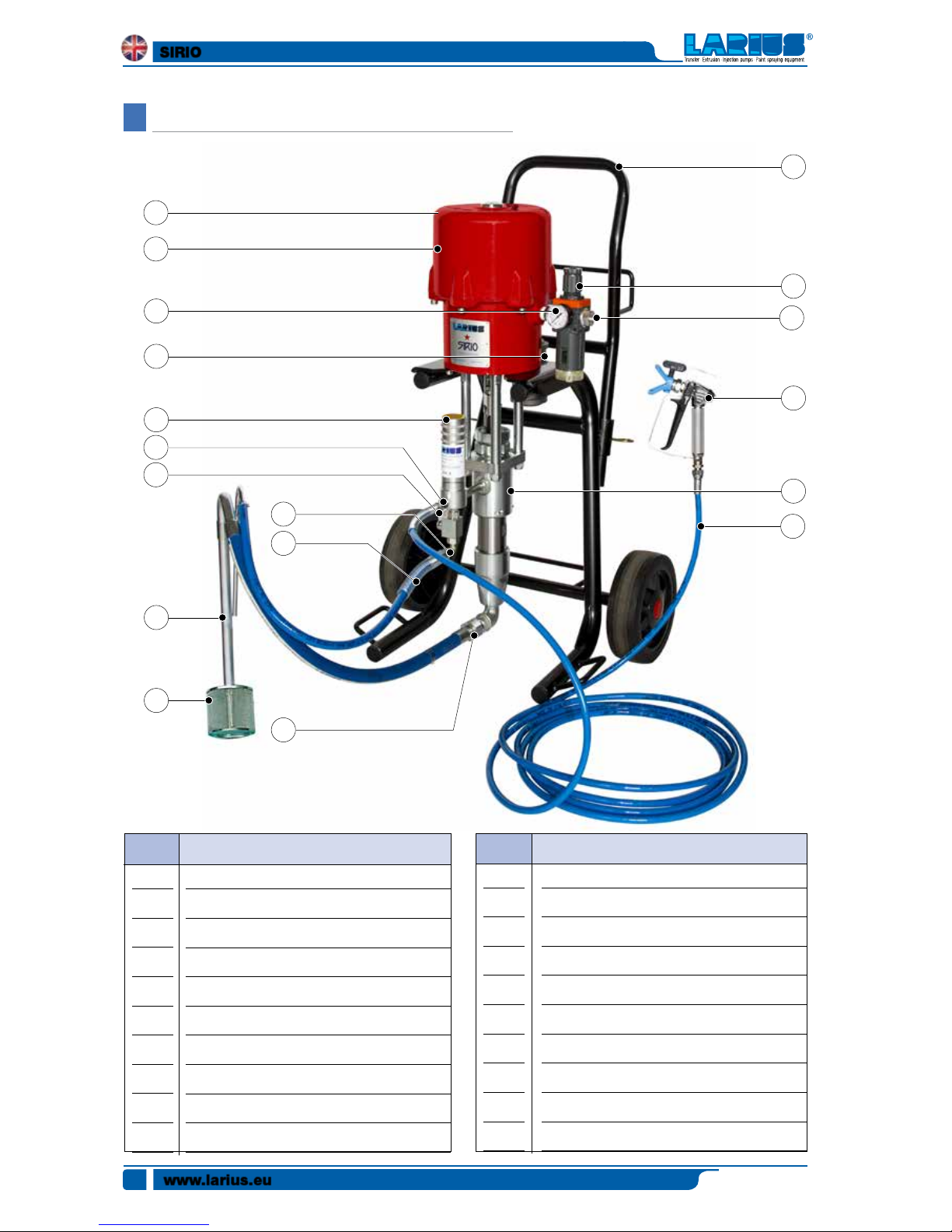
DESCRIPTION OF THE EQUIPMENT
POS.
1
2
3
4
5
6
7
8
9
10
Compressed air inlet
Manometer reading air pressure alim. pump
Feed air pressure regulator. pump
Trolley transport equipment
Sound absorbing filter
Pneumatic motor pump
Filtro alta pressione uscita materiale
High pressure filter out material
Recirculating cock
Recirculation pipe fitting fixing
Description POS. Description
11
12
13
14
15
16
17
18
19
20
Fluid recirculation pipe
Material suction pipe
Material suction filter
Fitting pipe fitting intake
Material pumping group
Material flexible pipe
Spray technology
Cable grounding with gripper
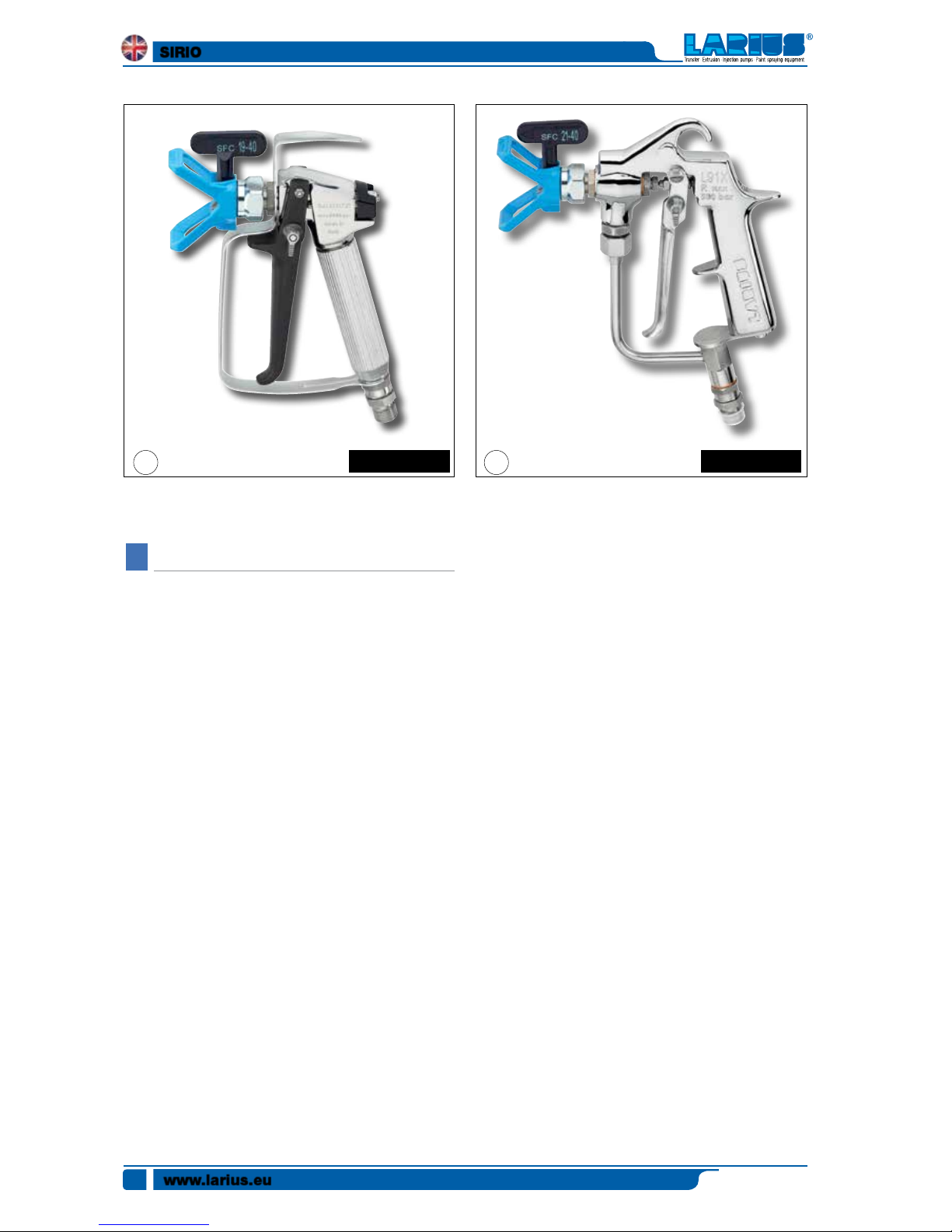
Gun AT250 - OPTIONAL
Gun L91 - OPTIONAL
1
3
2
4
6
7
8
9
10
11
12
13
14
15
16
17
18
5
SIRIO
Ediz. 006 - 12/2017
www.larius.eu
9
18
3
1
9
7
8
10
6
2
air
5
16
13
12
11
SIRIO
Ediz. 006 - 12/2017
www.larius.eu
10
D
19
Gun AT250
20
Gun L91
TRANSPORT AND UNPACKING
• Thepackedpartsshouldbehandledasindicatedinthe
symbols and markings on the outside of the packing.
• Beforeinstallingtheequipment,ensurethattheareato
be used is large enough for such purposes, is properly
lit and has a clean, smooth floor surface.
• Theuserisresponsiblefortheoperationsofunloading
and handling and should use the maximum care so as
not to damage the individual parts or injure anyone.
To perform the unloading operation, use only qualified
and trained personnel (truck and crane operators, etc.)
and also suitable hoisting equipment for the weight of
the installation or its parts.
Follow carefully all the safety rules.
The personnel must be equipped with the necessary
safety clothing.
• The manufacturer will not be responsible for the unlo-
ading operations and transport to the workplace of the
machine.
• Checkthepacking is undamaged on receipt of the
equipment. Unpack the machine and verify if there has
been any damage due to transportation.
In case of damage, call immediately LARIUS and the
Shipping Agent. All the notices about possible damage
or anomalies must arrive timely within 8 days at least
from the date of receipt of the plant through Registered
Letter to the Shipping Agent and to LARIUS.
• Thedisposal ofpackaging materialsisa customer’s
competence and must be performed in accordance with
the regulations in force in the country where the plant is
installed and used.It is nevertheless sound practice to
recycle packaging materials in an environment-friendly
manner as much as possible.
OPTIONAL OPTIONAL
SIRIO
Ediz. 006 - 12/2017
www.larius.eu
11
E
SAFETY RULES
•
THE EMPLOYER SHALL TRAIN ITS EMPLOYEES
ABOUT ALL THOSE RISKS STEMMING FROM ACCI
DENTS, ABOUT THE USE OF SAFETY DEVICES FOR
THEIR OWN SAFETY AND ABOUT THE GENERAL
RULES FOR ACCIDENT PREVENTION IN COMPLIANCE
WITH INTERNATIONAL REGULATIONS AND WITH THE
LAWS OF THE COUNTRY WHERE THE PLANT IS USED.
THE BEHAVIOUR OF THE EMPLOYEES SHALL STRICTLY
COMPLY WITH THE ACCIDENT PREVENTION AND ALSO
ENVIRONMENTAL REGULATIONS IN FORCE IN THE
COUNTRY WHERE THE PLANT IS INSTALLED AND USED.
Read carefully and entirely the following
instructions before using the product. Please
save these instructions in a safe place.
The unauthorised tampering/replacement of
one or more parts composing the machine,
the use of accessories, tools, expendable
materials other than those recommended
by the Manufacturer can be a danger of
accident.
The Manufacturer will be relieved from tort
and criminal liability.
• KEEP YOUR WORK PLACE CLEAN AND TIDY. DISORDER
WHERE YOU ARE WORKING CREATES A POTENTIAL
RISK OF ACCIDENTS.
• ALWAYS KEEP PROPER BALANCE AVOIDING UNUSUAL
STANCE.
• BEFORE USING THE TOOL, ENSURE THERE ARE NOT
DAMAGED PARTS AND THE MACHINE CAN WORK PROPERLY.
• ALWAYS FOLLOW THE INSTRUCTIONS ABOUT SAFETY
AND THE REGULATIONS IN FORCE.
• KEEP THOSE WHO ARE NOT RESPONSIBLE FOR THE
EQUIPMENT OUT OF THE WORK AREA.
• NEVER EXCEED THE MAXIMUM WORKING PRESSURE
INDICATED.
• NEVER POINT THE SPRAY GUN AT YOURSELVES OR
AT OTHER PEOPLE. THE CONTACT WITH THE CASTING
CAN CAUSE SERIOUS INJURIES.
• IN CASE OF INJURIES CAUSED BY THE GUN CASTING,
SEEK IMMEDIATE MEDICAL ADVICE SPECIFYING THE
TYPE OF THE PRODUCT INJECTED. NEVER UNDERVALUE
A WOUND CAUSED BY THE INJECTION OF A FLUID.
• ALWAYS DISCONNECT THE SUPPLY AND RELEASE THE
PRESSURE IN THE CIRCUIT BEFORE PERFORMING
ANY CHECK OR PART REPLACEMENT OF THE EQUIPMENT.
• NEVER MODIFY ANY PART IN THE EQUIPMENT. CHECK
REGULARLY THE COMPONENTS OF THE SYSTEM.
REPLACE THE PARTS DAMAGED OR WORN.
•
TIGHTEN AND CHECK ALL THE FITTINGS FOR
CONNECTION BETWEEN PUMP, FLEXIBLE HOSE
AND SPRAY GUN BEFORE USING THE EQUIPMENT.
• ALWAYS USE THE FLEXIBLE HOSE SUPPLIED WITH
STANDARD KIT.
• THE USE OF ANY ACCESSORIES OR TOOLING OTHER
THAN THOSE RECOMMENDED IN THIS MANUAL, MAY
CAUSE DAMAGE OR INJURE THE OPERATOR.
• THE FLUID CONTAINED IN THE FLEXIBLE HOSE CAN
BE VERY DANGEROUS. HANDLE THE FLEXIBLE HOSE
CAREFULLY. DO NOT PULL THE FLEXIBLE HOSE TO
MOVE THE EQUIPMENT. NEVER USE A DAMAGED OR A
REPAIRED FLEXIBLE HOSE.
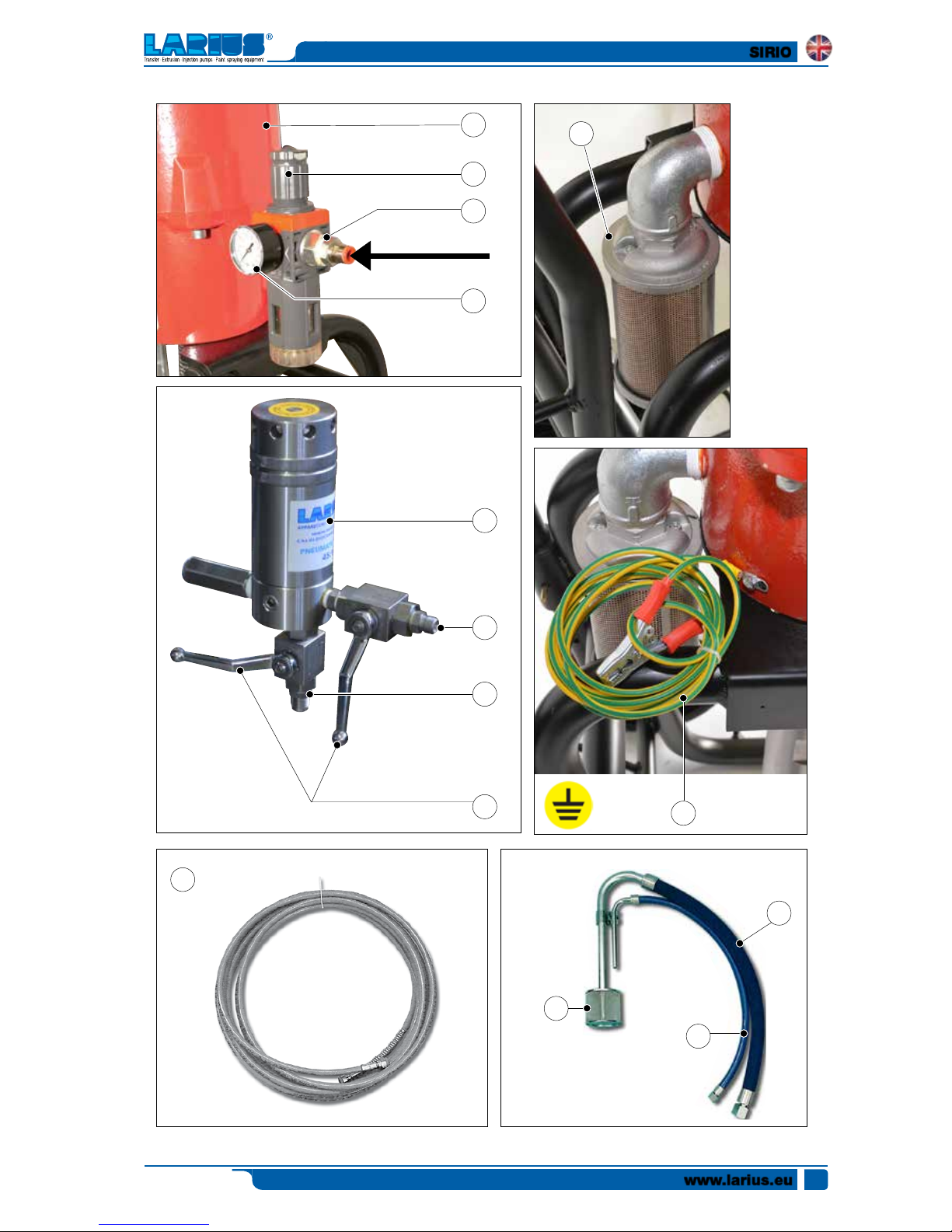
The high speed of travel of the product in the
hose can create static electricity through
discharges and sparks. It is suggested to earth
the equipment. The pump is earthed through
the earth cable of the supply.
The gun is earthed through the high pressure flexible hose.
All the conductors near the work area must be earthed.
• NEVER SPRAY OVER FLAMMABLE PRODUCTS OR SOL-
VENTS IN CLOSED PLACES.
• NEVER USE THE TOOLING IN PRESENCE OF POTEN-
TIALLY EXPLOSIVE GAS.
Always check that the product is compatible
with the materials composing the equipment
(pump, spray gun, flexible hose and accessories)
with which it can come into contact. Never
use paints or solvents containing Halogen
Hydrocarbons (as the Methylene Chloride). If these products
come into contact with aluminium parts can provoke
dangerous chemical reactions with risk of corrosion and
explosion.
Avoid approaching too much to the pump pi-
ston rod when the pump is working or under
pressure. A sudden movement of the piston
rod can cause wounds or finger squashing.
SIRIO
Ediz. 006 - 12/2017
www.larius.eu
12
TAKE PROPER SAFETY MEASURES FOR THE PROTECTION
OF HEARING IN CASE OF WORK NEAR THE PLANT.
F
SETTING-UP
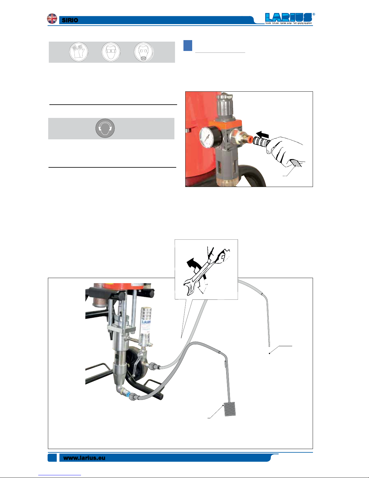
CONNECTION TO THE FEED AIR
For pump feed use a hose (F1) with an internal diameter no
lower than 10 mm.
CONNECTION OF SUCTION AND RECIRCULATING PIPES
•Connect the suction and recirculating pipes to the pump.
The suction hose can be locked finger tight (F1). Use a spanner
to tighten the recirculating pipe (F2). In both cases do not use
sealant agents for fitting threads.
IF THE PRODUCT TO BE USED IS TOXIC, AVOID INHALATION
AND CONTACT BY USING PROTECTION GLOVES, GOGGLES
AND PROPER FACE SHIELDS.
F1
F2
F1
SIRIO
Ediz. 006 - 12/2017
www.larius.eu
13
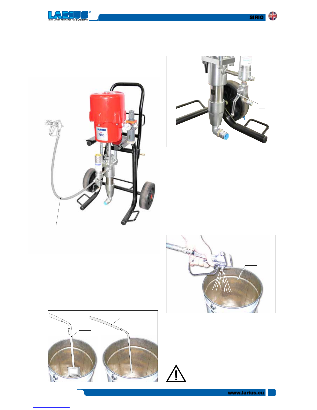
PREPARATION OF THE PAINT
•Ensure the product is suitable to be used with a spray gun.
•Mix and filter the product before using it. For filtration, the
use of close-mesh (Ref. 214) and large-mesh (Ref. 215) LARIUS
METEX braids is suggested.
Make sure the product to be used is compatible
with the materials employed for manufacturing
the equipment. For this reason, please contact
the supplier of the product.
CONNECTION OF SUCTION AND RECIRCULATING PIPES
AIRLESS version
•Connect the high pressure flexible hose (F3) to the pump
and to the spray gun, paying attention to tighten the fittings
strongly (the use of two spanners is suggested). Do not use
sealant agents for fitting threads.
•Makesurethesprayguniswithouttheatomizationnozzle.
WASHING OF THE BRAND-NEW EQUIPMENT
•The equipment has been tested at our plant with light mineral
oil left inside of the pumping element as protection. Therefore,
before sucking the product, carry out a washing using a diluent.
•Dip the suction hose (F4) into the tank of the washing.
•Insert the recirculating pipe (F5) into a container (a metal
container is suggested).
•Open the recirculating cock (F6).
F5
F4
•Set the pump feed pressure at about 3 bar and open the air
passage valve.
•The pump will start working and will drain oil from the recirculating pipe. Close the recirculating cock (F6) as soon as the
clean solvent has come out.
•Lift the solvent tank’s suction tube.
•Lean the spray gun against the rim of the container (F7) and
drain the residual oil pressing the trigger. Release the trigger
as soon as the clean solvent comes out.
•Point the spray gun at the tank of the solvent and press the
trigger so as to recover the clean solvent left inside the pump.
•As an accelerated working of the pump (the pump “idles”)
appears, close the air passage valve.
F7
F3
F6
SIRIO
Ediz. 006 - 12/2017
www.larius.eu
14
sideways (right-left) when spraying.
• Always paint with regular parallel bands coats.
• Keep a safety and constant distance between the spray
gun and the support to be painted and keep yourselves
perpendicular to it.
Never point the spray gun at your selves or at
other people. The contact with the cating can
cause serious injuries.
H
CLEANING AT THE END OF
THE WORK
• Lift the suction hose from the tank of the product.
• Reduce the pump feed pressure to about 3-4 bar and
open te recirculating cock so as to recover the product
left inside the equipment.
• Close the air passage valve for pump feed.
• Point the spray gun at the tank of the solvent and press
the trigger so as to recover the clean solvent left inside
the pump.
• Remove the nozzle from the spray gun (Do not forget to
clean it using a solvent!).
• Dip the suction hose into the tank of the washing solvent
(ensure it is compatibile with the product being used).
• Insert the recirculating hose into a container (a metal con-
tainer is recommended).
• Open the recirculating cock.
• Open the air passage valve in order to start up the pump.
• Close the recirculating cock as soon as a clean solvent
comes out.
• Lift the solvent tank’s suction tube.
• Point the spray gun at the tank of the solvent and press
the trigger so as to recover the clean solvent left inside
the pump.
• As an accelerated working of the pump (the pump “idles”)
appears, close the air passage valve .
•
In case of long storage, we recommend you to suck and to leave
light mineral oil inside the pumping group and the flexible hose.
• In this case, please follow the washing procedure described
on page 8 before using the tooling.
Store possible dangerous fluids in proper
containers. Their disposal must be performed
in accordance with the regulations in force
about the industrial waste goods.
G
WORKING
• Use the machine after carrying out all the setting-up operations described in the previous paragraph.
Check all the fittings for connection of the
different components (pump, flexible hose,
spray gun, etc.) before using the equipment.
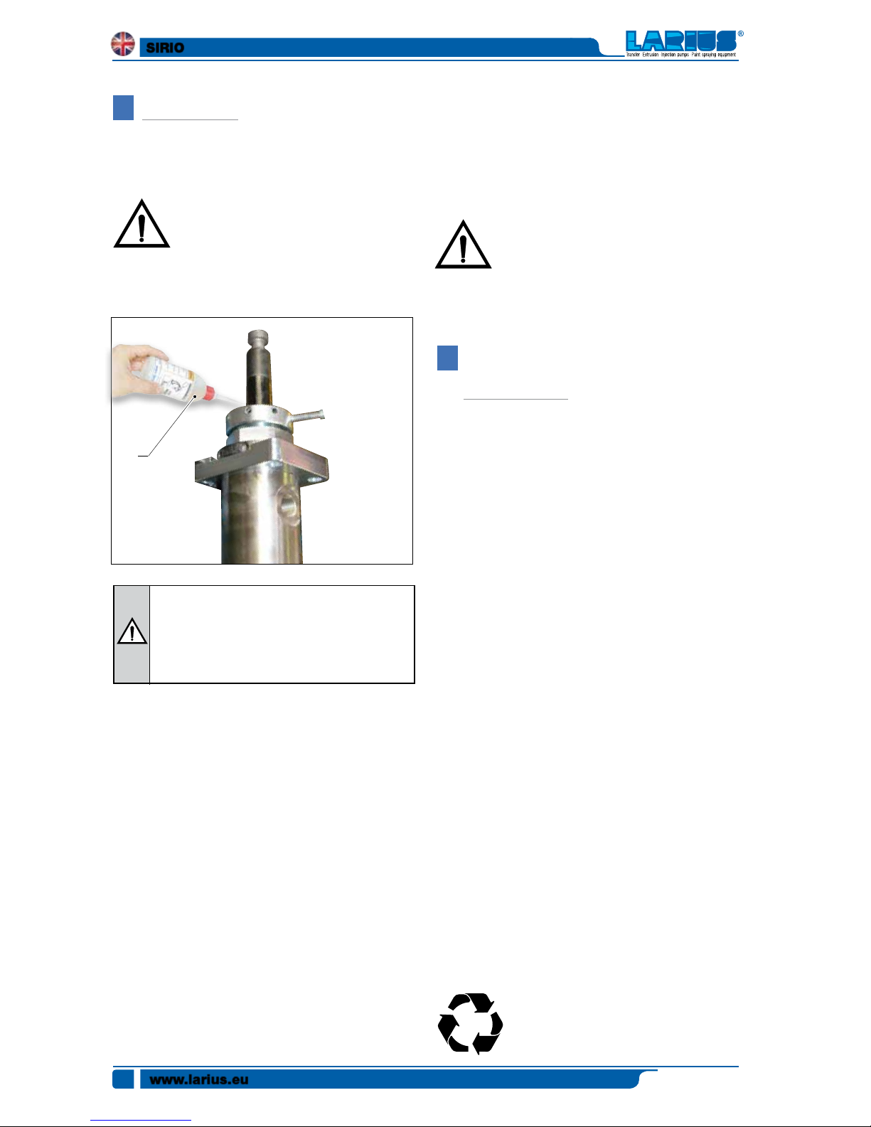
• Use the supplied lubricant (G1 - ref. 16325)
to facilitate the sliding of the piston inside the seal packing
and to interpose the oil within the air.
At the start of each working day, make sure that the
ring nut is filled with hydraulic oil (ref. 16325); the
oil facilitates the sliding of the piston and prevents
any material which may have leaked out of the seals
from drying once the equipment has been shut off.
• Fix the atomization nozzle on the spray gun. Select the
right nozzle according to the characteristics of the material
to be used and to the type of work to be performed.
• Dip the suction and recirculating pipes into the tank of the
product.
• Open the recirculating cock.
• Set the pump feed pressure at about 3-4 bar and open
the air passage valve.
• Allow the product to circulate for a few seconds. Then
close the recirculating cock. The pump will keep on working
until the high pressure flexible hose is full of product up
to the spray gun. Then the pump will stop automatically.
• Increase pump feed pressure so as to reach a pressure
value to guarantee a good atomization of the product.
• An irregular and marked spray on the sides indicates a
low working pressure. On the contrary, a too high pressure
causes a high fog (“overspray”) and waste of product.
• In order to avoid overthick ness of paint, let the gun advance
G1
SIRIO
Ediz. 006 - 12/2017
www.larius.eu
15
I
ROUTINE MAINTENANCE
Always close the compressed air supply and release the pressure in the plant before performing
any check or maintenance of the pump.
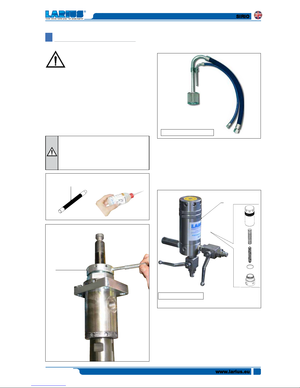
RING NUT CHECK
• Check periodically (and every time the pump is operated
after a long storage) the packing nut is not loosened, cau-
sing otherwise the coming out of the product.
To tighten the packing nut (I1) use wrench supplied
(I2). The packing nut must be tightened so as to avoid
wastes of product, but not excessively to avoid the
seizure of the pumping piston and the wear of seals.
In case of persistent coming out of product, replace
the seals.
MATERIAL SUCTION FILTER
• Remove and clean the material suction filter (I3).
HIGH PRESSURE FILTER CLEANING
• Remove and clean the high pressure filter for material
outlet (I4).
• Check periodically the air supply to the pump. Ensure the
air is always clean and lubricated.
At the start of each working day, make sure that the
ring (I1) nut is filled with hydraulic oil (ref. 16340); the
oil facilitates the sliding of the piston and prevents
any material which may have leaked out of the seals
from drying once the equipment has been shut off.
MATERIAL SUCTION FILTER
MATERIAL OUTPUT FILTER
I3
I4
I2
Rif. 16340
I1

SIRIO
Ediz. 006 - 12/2017
www.larius.eu
16
J
DISMANTLING AND REASSEMBLING THE PUMPING UNIT
2a
Necessary tools and equipment
Procedure
1.1 Remove the high pressure filter unit from the pump
Procedure
3.1 Unscrew and remove the
bottom valve body (3a)
1
Necessary tools and equipment
Procedure
2.1 Remove nuts (2a)
2
2a
Necessary tools and equipment
3
3a
3a

SIRIO
Ediz. 006 - 12/2017
www.larius.eu
17
Necessary tools and equipment
Necessary tools and equipment
Necessary tools and equipment
Procedure
4.1 Remove the gasket (4a)
4.2 Remove the components (4b, 4c, 4d)
4.3 Clean and lubricate the gasket housing and replace it with
a spare part
4.4 Reassemble the components (4a,
4b, 4c, 4d)
Procedure
5.1 Loosen the ring nut (5a) without removing it
Procedure
6.1 Unscrew and remove the component (6a)
4
5
6
4b 4c
5a
4d
6a
6a
CLEANER
4a
4a
4b
4d
4c

SIRIO
Ediz. 006 - 12/2017
www.larius.eu
18
Necessary tools and equipment
Procedure
8.1 Using a rubber mallet (8a),
slide off the component (8b)
8
Necessary tools and equipment
Procedure
9.1 Remove the gaskets (9a, 9b) clean and lubricate the gasket housing
and replace them with new spare parts
9
Procedure
7.1 Remove the gasket (7a)
7.2 Clean and lubricate the gasket housing
7.3 Replace the gasket with a spare part
7
8b
9a 9b
Necessary tools and equipment
7a
CLEANER
8a8b
CLEANER
9a 9b

SIRIO
Ediz. 006 - 12/2017
www.larius.eu
19
10
Procedure
10.1 Unscrew and remove the
component (10a)
Procedure
11.1 Remove the complete gasket pack (11a)
11
Procedure
12.1 Remove the component (12a)
12.2 Clean and lubricate the gasket
housing and replace it with the
new one (12b)
12.3 Reassemble the component (12a)
12
12a
10a
10a
Necessary tools and equipment
11a
CLEANER
12b
12a

SIRIO
Ediz. 006 - 12/2017
www.larius.eu
20
Procedure
13.1 Clean and lubricate the gasket housing
and replace it with the new spare
parts (13a)
A: Female STEEL ring
B: PTFE V seal ring
C: POLYPROPYLENE V seal ring
D: Male STEEL ring
E: Gasket housing
Follow the direction of rotation
of gaskets
NOTE
Direction
of assembly
13
Necessary tools and equipment
14
Procedure
14.1 Reassemble the component (14a)
14a
14a
CLEANER
13a
A
B
C
B
C
B
D
E

SIRIO
Ediz. 006 - 12/2017
www.larius.eu
21
Procedure
13.1 Using a 36mm wrench, un
screw and remove the
component (13a)
15
Necessary tools and equipment
Necessary tools and equipment
16
Procedure
14.1 Remove the complete gasket pack (14a)
14.2 Clean and lubricate the gasket housings and replace them
with new spare parts
A: Male STEEL ring
B: PTFE V gasket
C: POLYETHYLENE V gasket
D: Female STEEL ring
E: Ball
F: Piston valve
A: Anello maschio in ACCIAIO
B: guarnizione in PTFE V
C: guarnizione in POLYETHYLENE V
D: Anello femmina in ACCIAIO
E: Sfera
F: Valvola pistone
Direction
of assembly
Direction
of assembly
Follow the direction of
rotation
of gaskets
Follow the direction of
rotation
of gaskets
NOTE NOTE
155 cc 180 cc
13a
CLEANER
14a
A
B
C
B
C
B
C
B
D
E
F
A
B
C
B
C
B
D
E
F

SIRIO
Ediz. 006 - 12/2017
www.larius.eu
22
Procedure
17.1 Clean and lubricate the threaded area
17.2 Using a 36mm wrench,
reassemble the component (17a)
17
Necessary tools and equipment
Procedure
18.1 Reassemble the
component
(18a) as shown
in the figure (18b)
18
Necessary tools and equipment
Procedure
19.1 Insert the component (19a) inside the
component (19b)
19.1 Using a wrench, screw in the component (19a)
19
19b
17a
CLEANER
18a
18b
19a
19a
CLEANER

SIRIO
Ediz. 006 - 12/2017
www.larius.eu
23
Necessary tools and equipment
Procedure
20.1 Tighten the ring nut (20a)
20
Procedure
21.1 Reassemble the bottom valve body (21a)
Necessary tools and equipment
21
Necessary tools and equipment
Procedure
22.1 Reassemble the nuts (22a)
22
20a
21a
21a
CLEANER
22a
22a

SIRIO
Ediz. 006 - 12/2017
www.larius.eu
24
K
MANUAL RESET OF THE PNEUMATIC MOTOR
• The feed air pressure of the pump must never be higher
than the maximum value indicated in the technical data.
Exceed this value can block the valves of the pneumatic
motor in the intermediate position of the cycle reversal.
• Tostartagain ablockedmotor,close theairsupply and
release pressure in the plant. This operation should allow
the recovery of the valves.
• Incasethemotorisblocked,proceedasfollows:
- Close the air supply to the pump and release the residual
pressure in the plant;
- unscrew the motor cap (K1) and pull it upward along
with the guide rod (K2) so as to manually trigger the stroke
inversion unit;
- screw again the plug.
Necessary tools and equipment
Procedure
1.1 Reassemble the high pressure filter unit
on the pump
1
K1
K2

SIRIO
Ediz. 006 - 12/2017
www.larius.eu
25
L
DISMANTLING AND REASSEMBLING THE PNEUMATIC MOTOR
Procedure
1.1 Close the compressed air supply to the pump and release
the residual pressure in the plant.
1.2 Unscrew the motor cap (
1a
) and pull it upwards together
with the guide rod (1b) (1e)
1.3 Hold the guide rod (
1b
) and remove the plug (1a) (using
two wrenches).
1
Necessary tools and equipment
Replace immediately the plug with a usual M8 (1C) nut
before the guide rod (1B) slides into the cylinder (1D).
1e
1a
1a
1b
1c
1a
1b
1b
1c
1c
1d
1c

SIRIO
Ediz. 006 - 12/2017
www.larius.eu
26
2
Necessary tools and equipment
Procedure
2.1 Remove the screws (2a) and the washers (2b). (2c)(2d)
Procedure
3.1 Carefully extract the motor cylinder (3a) fom the pump.
3
3a
2c 2d
2b
2a

SIRIO
Ediz. 006 - 12/2017
www.larius.eu
27
Necessary tools and equipment
Procedure
4.1 Unscrew the nut (4a), holding the guide rod with a 7mm wrench.
Then reassemble the cap (4b).
4
Procedure
5.1 Press at the point (5a) to snap inside the rocker arm stud screw
Procedure
6.1 Unscrew and remove the two screws (6a, 6b) with 2 13mm wrenches as shown in figure (6c)
5
6
Necessary tools and equipment
4a
4b
5a
6a
6b
6c

SIRIO
Ediz. 006 - 12/2017
www.larius.eu
28
Necessary tools and equipment
Necessary tools and equipment
Procedure
8.1 Remove the two valve screws (8a, 8b)
Procedure
9.1 Proceed with disassembly and replace the 6 seal
sleeves (9a) with pliers
8
9
Necessary tools and equipment
Procedure
7.1 Use a screwdriver to lever the
lower part of the stud screw
(7a), keeping a hand over the
cap to accompany it. (7b)
7
7a
7b
8b
8a
9a
9a
9a

SIRIO
Ediz. 006 - 12/2017
www.larius.eu
29
Necessary tools and equipment
Procedure
10.1 Lubricate the springs (10a, 10b).
10
Procedure
12.1 Reassemble the two valve screws
(12a) as shown in the drawing
11
12
Necessary tools and equipment
Necessary tools and equipment
Procedure
11.1 Remove the OR gasket (11a) and replace it if necessary
with a spare part
CLEANER
12a
Follow the direction of rotation
of gaskets
NOTE
10a
10b
11a

SIRIO
Ediz. 006 - 12/2017
www.larius.eu
30
Procedure
12.2 Reassemble the two valve
screws, inserting a 3.5 mm
thickness gauge as shown
in the drawing and adjusting
the exact position of the
stud screw as shown in the
drawing, keeping a tolerance
distance of 3.5 mm
Make adjustments in the same way
on both valve screws
NOTE
Necessary tools and equipment
Procedure
13.1 Unscrew the cap (13a), holding the guide rod with a 7mm wrench.
Then reassemble the nut (13b).
13
3,5 mm
of the stud screw
valve screw
13b
13a

SIRIO
Ediz. 006 - 12/2017
www.larius.eu
31
15
Necessary tools and equipment
Procedure
15.1 Re-screw in the 6 screws (
15a
) and the washers (
15b
). (15c)(15d)
Procedure
14.1 Lubricate the gasket (14a)
14.2
Carefully reassemble the motor cylinder (14b) on the pump.
14
Necessary tools and equipment
14a
14a
15b
15a
15c 15d

SIRIO
Ediz. 006 - 12/2017
www.larius.eu
32
Procedure
16.1
Raise the central guide rod (16b) from inside the cylinder
(16d)
16.2
Remove the nut (16c)
16.3
Re-screw the cap (16a) onto the rod using 2 wrenches
and re-screw in the cap on the cover (16e)
16
Necessary tools and equipment
16a
16b
16c
16a
16b
16c
16c
16d
16c
16e

SIRIO
Ediz. 006 - 12/2017
www.larius.eu
33
M
PROBLEMS AND SOLUTION
Solution
Possible cause
Problem
• The pump does not start
• Accelerate working and no
pressure of the pump
• The pump functions, but doesn’t
stop when the chamber is full (the
pump continues slowly, increasing
and/or decreasing)
• The pressure of the material is
significantly reduced when the
trigger is pressed
• Feed air not sufficient;
• Outlet product line clogged;
• Clogged product intake line;
• Pneumatic motor blocked in the cycle
reversal position;
• Parts failure of the pneumatic motor;
• There is no product;
• The pump sucks air;
• Gaskets of the pumping rod worn;
• Suction valve worn or partially
clogged;
• Suction filter clogged;
• Suction filter too fine;
• Gaskets of the pumping rod worn;
• Suction valve worn or partially
clogged;
• Delivery valve worn or partially obstructed;
• Upper gaskets worn.
• The spray gun’s nozzle is too large
or worn
• Thespraygun’sfilterandthematerial
output filter’s sieve are too fine
• Check on the air supply line. Increase the diameter of the feed hose;
• Open the recirculation tap to
check whether the pump starts up.
Unscrew the high pressure filter
and clean/replace the filter sieve.
Clean/replace the spray gun’s filter.
• Cleanthesuctionfilter;
• Reduce feed air pressure;
• Disassemble the motor and verify;
• Add the product;
• Check the flexible suction tube;
• Replace the lower gaskets;
• Disassemble the suction valve.
Clean and/or replace, if possible,
the parts worn;
• Clean/replace the suction filter’s
two disks;
• Remove the fine disk, leaving only
the larger one inside;
• Replace the lower seals
• Disassemble the suction valve.
Clean and/or replace, if possible,
the parts worn;
• Remove the delivery valve and
clean/replace any worn parts;
• Tighten the packing nut.
• Replace it with a smaller one
• Replace them with filters of a larger
mesh size
Always close the compressed air supply and release the pressure in the plant before performing any check or
replacement of parts of the pump.

SIRIO
Ediz. 006 - 12/2017
www.larius.eu
34
White page
intentionally

SIRIO
Ediz. 006 - 12/2017
www.larius.eu
35
SPARE PARTS
N
Complete pneumatic motor
pag. 36
O
O
Pneumatic regulator
pag. 37
S
Complete trolley
pag. 41
T
U
pag. 42
Pumping unit coupling kit
pag. 43
Pumping 155cc (32:1)
pag. 38
Pumping 180cc (27:1)
pag. 39
Pumping unit: Filter Assembly
pag. 40
P
Q
R

SIRIO
Ediz. 006 - 12/2017
www.larius.eu
36
N
COMPLETE PNEUMATIC MOTOR
Ref. 99100
SCREW VALVE COMPLETA
RIF. 99068
COMPLETE ROCKER ARM
RIF. 99066
BUSH
RIF. 96017
40
39
38
31
29
28
27
37
26
25
24
23
19
18
17
16
15
14
13
4
1
5
7
6
3
2
9
10
NOT INCLUDED
IN THE MOTOR ASSEMBLY
11
12
8
34
33
32
30
22
21
20
35
36

SIRIO
Ediz. 006 - 12/2017
www.larius.eu
37
WARNING: always indicate code and quantity for each part required.
WARNING: always indicate code and quantity for each part
required.
Pos.
Complete motor
Motor base
Washer Ø 10
Screw
Elbow Fitting
Sound Absorbing Filter
Screw
Ground. Plate
Grounding Cable
ivet
Machine Plate
T. Sirio 32:1 Technical Data Plate
T. Sirio 27:1 Technical Data Plate
Shearing Plate
O-ring
O-ring
Seal Ring
Brass Bearing
Guide Bushing
Piston rod
Washer
Piston
Valve Screw
Valve Gasket
Code Description
,
1
2
3
4
5
6
7
8
9
10
11
11
12
13
14
15
16
17
18
19
20
21
22
23
24
25
26
27
28
29
30
31
32
33
34
35
36
37
38
39
40
41
Q.ty
-
1
6
6
1
1
1
1
1
12
1
1
1
1
1
1
1
1
1
1
1
1
2
2
99100
96050
33005
16111
99270
99054
96211
96210
5010
34020
99052
99064
99065
99069
99055
99056
96019
96017/1
96017/2
96016
33031
99051
99057
99058
PNEUMATIC REGULATOR UNIT ASSEMBLY Rif. 99291
Pos.
Guide Spring
Screw
O-ring
Seal Bushing
Exchange Spring
Roller
Fork
Rocker lever
Fork pin
Nut
Washer Ø 8
Gasket
Crosspiece
Guide Bushing
Guide Rod
Motor cylinder
O-ring
Cap
ATEX Plate
Code Description Q.ty
2
2
1
6
2
2
2
1
2
4
4
4
1
2
1
1
1
1
1
96011
96025
99059
96009
99061
99060
96007
96008
96024
4108
32024
96111
99062
96112
96010
99053
95075
96001
99041
NOT INCLUDED IN THE MOTOR ASSEMBLY
1
2
3
Pos.
Seal Washer
Nipple
Pneumatic Regulator
Code Description Q.ty
1
1
1
91622
95090
99290
3
2
1
O

SIRIO
Ediz. 006 - 12/2017
www.larius.eu
38
P
PUMPING 155 cc (32:1) Ref. 155050
11
12
4
3
3A
3A
2
13
14
15
16
17
18
1
2
3
4
5
6
7
8
9
10
8
WARNING: always indicate code and quantity for each part required.
Pos. Pos.Code CodeDescription DescriptionQ.ty Q.ty
Complete pumping 155cc (32:1)
Gaskets ring nut
Female ring
Gasket PTFE V
Polyethylene gasket V
Male ring
Gasket holder
O-ring
Pumping group
O-ring
Locking ring nut
Sleeve
Piston rod
Rondella pistone
Ball
Pumping piston
Ball guide
Ball locking pin
Ball
Bottom valve body
1
2
6
4
2
1
1
1
2
1
1
1
1
1
1
1
1
1
1
_
1
2
3
3A
4
5
6
7
8
9
10
11
12
13
14
15
16
17
18
155050
155011
155012
155007/1
155007/2
155006
155013
155014
155015
155016
155022
155017
155001
155005
35163
155010
155019
155018
20149
155021
PUMPING 155 cc (32:1)

SIRIO
Ediz. 006 - 12/2017
www.larius.eu
39
Q
PUMPING 180 cc (27:1) Ref. 180050
WARNING: always indicate code and quantity for each part required.
Pos. Pos.Code CodeDescription DescriptionQ.ty Q.ty
Complete pumping 180cc (27:1)
Gaskets ring nut
Female ring
Gasket PTFE V
Polyethylene gasket V
Male ring
Gasket holder
O-ring
Pumping group
O-ring
Locking ring nut
Sleeve
Piston rod
Ball
Pumping piston
Ball guide
Ball locking pin
Ball
Bottom valve body
1
2
6
4
2
1
1
1
2
1
1
1
1
1
1
1
1
1
-
1
2
3
3A
4
5
6
7
8
9
10
11
12
13
14
15
16
17
180050
180006
180004
180003/1
180003/2
180002
180007
155014
155015
155016
155022
180009
180001
35163
180005
155019
155018
20149
155021
PUMPING 180 cc (27:1)
11
4
3
3A
3A
2
12
13
14
15
16
17
1
2
3
4
5
6
7
8
9
10
8

SIRIO
Ediz. 006 - 12/2017
www.larius.eu
40
R
FILTER ASSEMBLY Ref. 99250
WARNING: always indicate code and quantity for each part required.
Pos. Code Description Q.ty
Filter assembly
Warning Label
Filter Tank
Filter Sieve
Filter Sieve Support
O-ring
Fitting
Ball valve
Fitting
Cap
Fitting
1
1
1
1
1
1
2
2
1
1
,
1
2
3
4
5
6
7
8
9
10
99250
10107
99252
95218
65078
65099
6148
33037
6149/1
95214
3385
Pos. Code Description Q.ty
Seal Washer
Filter Base
Filter Inlet Fitting
27:1 label
32:1 label
1
1
1
1
1
11
12
13
14
14
33010
99251
99253
99042
99043
FILTER ASSEMBLY Ref 99250
1
2
3
4
6
7
8
9
7
10
8
12
13
11
5

SIRIO
Ediz. 006 - 12/2017
www.larius.eu
41
S
STANDARD COMPLETE TROLLEY Rif. 99150
WARNING: always indicate code and quantity for each part required.
Pos. Code Description Q.ty
Standard complete trolley
Base Trolley
Washer Ø 10
Screw
Tube Cap
Wheel
Wheel Stop Washer
Ø 40 Tube Cap
Wall Support
Heater Holder
Screw
Split pin
Bushing
1
4
4
2
2
2
6
1
1
2
2
2
,
1
2
3
4
5
6
7
8
9
10
11
12
99150
99153
33005
4408
95159
37238
20305
95229
99156
99154
6130
18902
99155
1
2
7
2
9
10
11
12
3
4
5
6
7
7
8
Heater assembly kit (MOD. 6099)
Ref. 99151
Wall support
Ref. 99157

SIRIO
Ediz. 006 - 12/2017
www.larius.eu
42
T
PAINT SUCTION SYSTEM
SPLIT
Ref. 85026
1
2
3
4
WARNING: always indicate code and quantity for each part required.
Pos.
Intake system
Suction pipe complete
Recirculation hose
Locking spring
Intake filter
85026
18097
16613
18096
37216
1
2
3
4
Code Description

SIRIO
Ediz. 006 - 12/2017
www.larius.eu
43
U
PUMPING UNIT COUPLING KIT Ref. 99280
WARNING: always indicate code and quantity for each part required.
Pos. Code Description Q.ty
Complete kit
Tie rod
Nut
Split pin
Or 3050
Joint sleeve
Nut
Pumping shaft connection
4
4
1
1
1
2
1
,
1
2
3
4
5
6
7
99280
99281
95013
3323
96073
99282
99284
99283

SIRIO
Ediz. 006 - 12/2017
www.larius.eu
44
V
ACCESSORIES
Code 11250: AT 250 1/4"
Code 11200: AT 250 M16x1,5
Code 11090: AT 300 1/4"
Code 11000: AT 300 M16x1,5
PISTON GUNSTOCK FILTERS
Code
11039: Green (30M)
Code
11038: White (60M)
Code
11037: Yellow (100M)
Code
11019: Red (200M)
Code 11131: L91X 1/4"
Code 11130: L91X M16x1,5
FILTRO
Code 95218: TAMIS 30M
Code 95219: TAMIS 60M
Code 95220: TAMIS 100M
Code 95221: TAMIS 200M
FITTING WITH MANOMETER
Code 147: M16x1,5
Code 150: 1/4"
Code
91044: PNEUMATIC MIXER
Code 7030: HP FLOW REGULATOR Code 6099: HEATER

SIRIO
Ediz. 006 - 12/2017
www.larius.eu
45
Code 18270: SUPER FAST-CLEAN
base
UE 11/16x16
Code 18280: GASKET
UGELLO SUPER FAST-CLEAN
SUPER FAST-CLEAN
Nozzle code
SFC07-20
SFC07-40
SFC09-20
SFC09-40
SFC11-20
SFC11-40
SFC13-20
SFC13-40
SFC13-60
SFC15-20
SFC15-40
SFC15-60
SFC17-20
SFC17-40
SFC17-60
SFC19-20
SFC19-40
SFC19-60
SFC21-20
SFC21-40
SFC21-60
SFC23-20
SFC23-40
SFC23-60
SFC25-20
SFC25-40
SFC25-60
SFC27-20
SFC27-40
SFC27-60
SFC27-80
SFC29-20
SFC29-40
SFC29-60
SFC29-80
SFC31-40
SFC31-60
SFC31-80
SFC33-40
SFC33-60
SFC33-80
SFC39-40
SFC39-60
SFC39-80
SFC43-40
SFC43-60
SFC43-80
SFC51-40
SFC51-60
SFC51-80
GUN EXTENSION
Code 153: cm 30 -Code 153: cm 40
Code 155: cm 60 - Code 158: cm 80 - Code 156: cm 100

PAINT SPRAYING EQUIPMENT
Innovation.
The real kind.

SIRIO
Ediz. 006 - 12/2017
www.larius.eu
47
NOVA
45:1 - 60:1 - 68:1
GHIBLI ZINC
30:1
SIRIO
27:1 - 32:1
SIRIO
plunger piston
30:1 - 45:1
SUPER NOVA
45:1 - 68:1 - 80:1
OMEGA ZINC
30:1
GHIBLI
30:1 - 40:1
OMEGA
23:1 - 30:1 - 34:1
SUPER OMEGA ZINC
34:1
VEGA
23:1
SUPER OMEGA
23:1 - 34:1 - 40:1
SUPER NOVA ZINC
45:1
AIRLESS PNEUMATIC PUMPS

LARIUS srl
Via Antonio Stoppani 21 - 23801 Calolziocorte (LC) ITALY
TEL. +39 0341 621152 - Fax +39 0341 621243 - larius@larius.com
Made in Italy 1969
www.larius.eu
 Loading...