

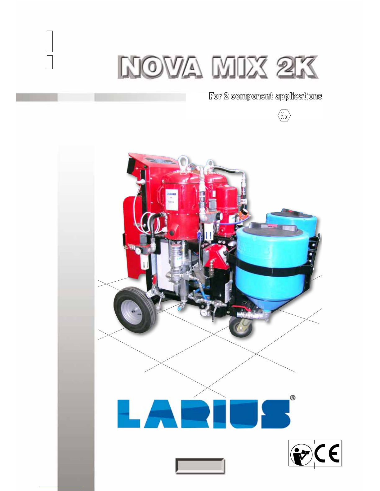
For 2 component applications
Certified stainless steel pump Atex II 2G c IIB T6
ENGLISH
OPERATING AND MAINTENANCE
INSTRUCTION
OPERATING AND MAINTENANCE
INSTRUCTION
PAINT SPRAYING EQUIPMENT
Ed.
010
11 - 11

Due to a constant product improvement programme, the factory reserves the right to modify technical details
mentioned in this manual without prior notice.
This manual is to be considered as an English language translation of the original manual in Italian. The
manufacturer shall bear no responsibility for any damages or inconveniences that may arise due to the incorrect
translation of the instructions contained within the original manual in Italian.
1
NOVA MIX 2K
English
START-UP PROCEDURES .................................. p.27
Manual mode ........................................................ p.27
Automatic mode .................................................... p.29
DESCRIPTION OF THE PANEL'S FUNCTIONS .. p.30
AUTOMATIC CYCLE ............................................ p.36
SPARE PARTS
MACHINE ASSEMBLY ......................................... p.40
CONTROL BOX ASSEMBLY ................................ p.41
PROTECTIVE CASING ASSEMBLY .................... p.42
ELECTRO-PNEUMATIC PANEL .......................... p.43
DOOR ASSEMBLY ............................................... p.44
GROUP FOR POWER MACHINE ........................ p.45
TANK ASSEMBLY KIT
........................................... p.46
PRESSURE EQUIPMENT ASSEMBLY
.................. p.47
LEFT BRAKE
.......................................................... p.48
RIGHT BRAKE ..................................................... p.49
MACHINE STEERING GEAR ASSEMBLY ........... p.50
AIR DISTRIBUTOR ASSEMBLY........................... p.51
PARTY WITH DRAIN ............................................ p.52
AIR DISTRIBUTOR ASSEMBLY........................... p.53
GROUP ASSEMBLY RL FOR NOVA PUMP ..... p.54
AIR SUPPLY TANK ............................................ p.55
AIR REGULATOR FOR WASH PUMP
...................... p.56
GHIBLI REDUCER ASSEMBLY ........................ p.57
ENCODER KIT FOR COMPONENT DOSAGE
.......... p.58
FLOWMETER KIT FOR GHIBLI MIX COMP. DOSAGE
.......... p.59
HEATER WITH A COMPONENT
............................. p.60
HEATER WITH B COMPONENT
............................. p.61
WHEELS ........................................................... p.62
MIXER + SPRAY GUNS .................................... p.63
SPRAY GUN EXPLODED LA 95 ....................... p.64
ACCESSORIES ................................................ p.66
INTRODUCTION .................................................. p.1
WARNINGS .......................................................... p.2
WORKING PRINCIPLE ........................................ p.3
TECHNICAL ......................................................... p.4
DESCRIPTION OF THE EQUIPMENT ................. p.5
TRANSPORT AND UNPACKING ......................... p.9
SAFETY RULES ................................................... p.10
CONDITIONS OF GUARANTEE .......................... p.11
SETTING-UP ........................................................ p.11
Product pump connection ................................ p.12
Check on power supply .................................... p.14
Connecting the equipment to the pneumatic
line ................................................................... p.15
Washing of the new equipment ........................ p.16
Preparing the product ...................................... p.16
WORKING ............................................................ p.17
Starting uo and charging the machine ............. p.17
Procedure for checking component dosage ..... p.19
Flow .................................................................. p.20
MAINTENANCE ................................................... p.21
Washing ........................................................... p.21
Decompression ................................................ p.22
Filter cleaning ................................................... p.23
Gasket pack regulation .................................... p.24
Cleaning afeter work activities ......................... p.25
Routine maintenance ....................................... p.25
Periodic maintenance (weekly) ........................ p.25
OPERATORE INTERFACE PANEL ...................... p.26
Operating panel................................................ p.26
Control panel .................................................... p.26
Alarm checks ................................................... p.26
Power status ..................................................... p.26
Locking selector ............................................... p.27
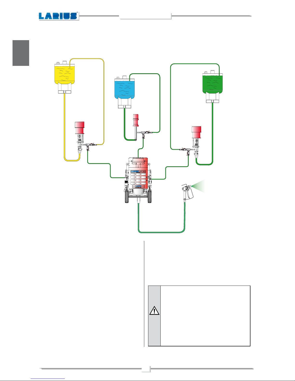
MULTICOMPONENT SYSTEM
MULTICOMPONENT SYSTEM
WE ADVISE THE USE OF THIS EQUIPMENT ONLY BY PROFESSIONAL OPERATORS.
ONLY USE THIS MACHINE FOR USAGE SPECIFICALLY MENTIONED IN THIS MANUAL.
Thank you for choosing a LARIUS S.R.L. product.
As well as the product purchased, you will receive a range of support services
enabling you to achieve the results desired, quickly and professionally.
A
B
C
D
E
F
G
H
M
N
O
P
Q
K
L
R
S
I
J
T
U
V
W
X
Y
Z
AA
AB
AC
AD
AE
AF
AG
AH
AI
AJ
AK
AL
2
NOVA MIX 2K
English
Read this operator’s manual carefully before using the equipment.
An improper use of this machine can cause injuries to people or things.
Do not use this machine when under the influence of drugs or alcohol.
Do not modify the equipment under any circumstances.
Use products and solvents that are compatible with the various parts of the equipment, and read the manufacturer’s warnings carefully.
See the Technical Details for the equipment given in the Manual.
Check the equipment for worn parts once a day. If any worn parts are found, replace them using ONLY original spare parts.
Keep children and animals away from work area.
Comply with all safety standards.
It indicates an accident risk or serious damage to equipment if this warning is not followed.
It indicates important recommendations about disposal and recycling process of products in accordance with the environmental
regulations.
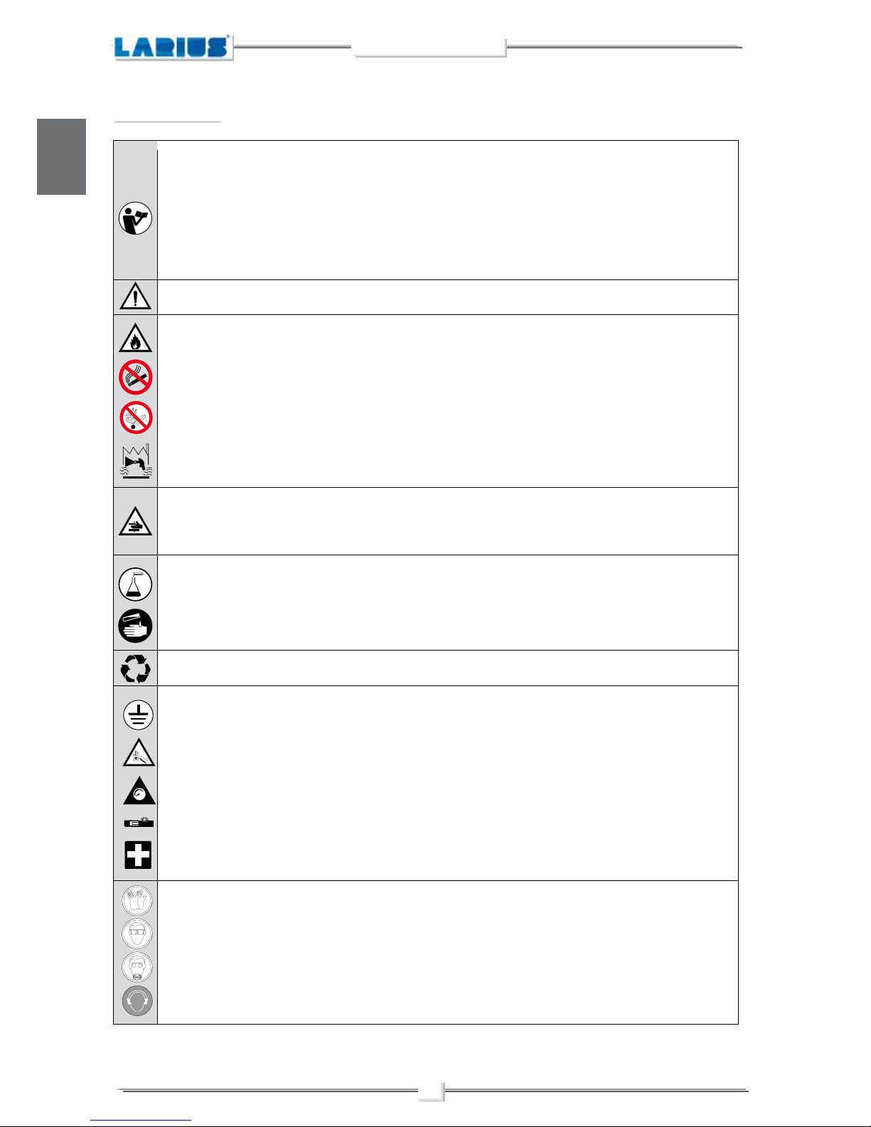
WARNINGS
The table below provides the meaning of the symbols used in this manual in relation to using, earthing,
operating, maintaining, and repairing of this equipment.
It indicates wound and finger squashing risk due to movable parts in the equipment.
Tenersi lontano dalle parti in movimento.
Do not use the equipment without the proper protection.
Before any inspection or maintenance of the equipment, carry out the decompression procedure explained in this manual, and prevent
any risk of the equipment starting unexpectedly.
Report any risk of chemical reaction or explosion if this warning has not been given.
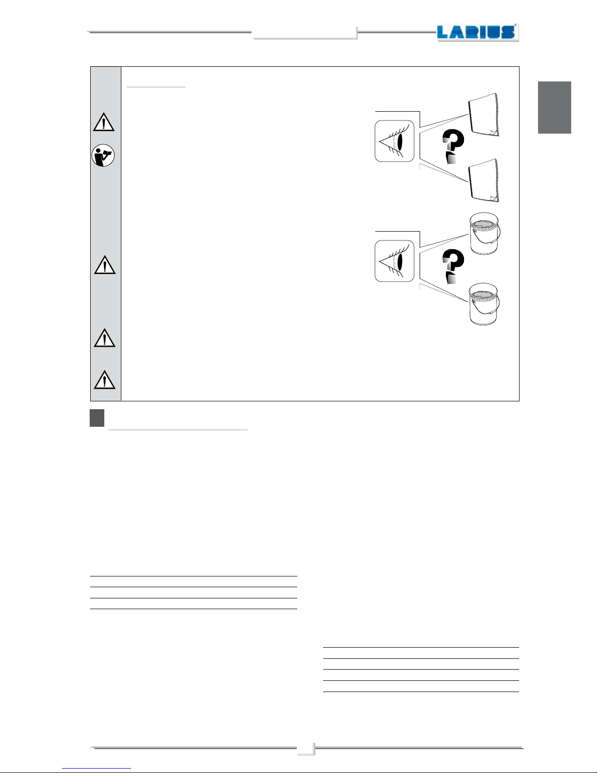
There is a risk of injury or serious lesion related to contact with the jet from the spray gun. If this should occur, IMMEDIATELY contact
a doctor, indicating the type of product injected.
Do not spray before the guard has been placed over the nozzle and the trigger on the spray gun.
Do not put your fingers in the spray gun nozzle.
Once work has been completed, before carrying out any maintenance, complete the decompression procedure explained in this manual.
Mark any clamps attached to earth cables.
Use ONLY 3-wire extension cords and grounded electrical outlets.
Before starting work make sure that the electrical system is earthed and that it complies with safety standards.
The high-pressure fluid that comes out of the gun or from possible leaks may cause injections into the body.
To prevent the risks of fire or injection:
- Use the safety lock of the gun trigger when you are not spraying.
- Do not place your hands or fingers on the gun nozzle. Do not attempt to stop leaks with your hands, body or anything else.
- Do not aim the gun at yourself or anyone else.
- Do not spray without the special nozzle protection.
- Release the system pressure after spraying and before any maintenance operation.
- Do not use components whose operating pressure is lower than the maximum system pressure.
- Do not allow children to use the equipment.
- Pay the utmost attention to possible recoil when pulling the gun trigger.
If the high-pressure fluid penetrates the skin, the wound may appear to be just a “simple cut”, but may actually be a very
serious injury. Immediately medicate the injured part.
It is obligatory to wear suitable clothing as gloves, goggles and face shield.
Wear clothing that complies with the safety standards in force in the country in which the equipment is used.
Do not wear bracelets, earrings, rings, chains, or anything else that may hinder the operator’s work.
Do not wear clothing with wide sleeves, scarves, ties, or any other piece of clothing that could get tangled up in moving parts of the
equipment during the work, inspection, or maintenance cycles.
0
0 BAR 0 PSI
FIRE AND DANGER OF EXPLOSIONS
Flammable fumes, such as solvent and paint fumes, may burst into flames or explode.
To prevent the risks of fire or explosion:
- ONLY use this equipment in a well ventilated area. Earth all the equipment located in the work area.
-
Eliminate all sources of sparks, such as pilot flames, cigarettes, portable electric torches, synthetic clothing (potential static arc) etc.
- Connect the equipment and all the conductive devices in the working area to ground.
- Use only conductive airless hoses and connect them to ground.
- Do not use tricloroethane, methylene chloride, other halogenated hydrocarbon solvents or fluids containing such solvents in pressurised aluminium equipment. Using these substances may cause a dangerous chemical reaction with the possibility of explosion.
- Do not form connections or switch light switches on or off if the air contains inflammable fumes.
If electrical shocks or discharges are encountered the operation being carried out using the equipment must be stopped immediately.
Keep a fire extinguisher at hand in the immediate vicinity of the work area.
3
NOVA MIX 2K
English
A
A
T
E
C
H
N
I
C
A
L
D
A
T
A
T
E
C
H
N
I
C
A
L
D
A
T
A
B
B
T
E
C
H
N
I
C
A
L
D
A
T
A
T
E
C
H
N
I
C
A
L
D
A
T
A
W
A
T
E
R
S
O
L
V
E
N
T
- The operator must possess and be familiar with the
data sheets of the 2 components (A and B).
- The operator must be familiar with the characteristics
of both the wash fluid to be used with the catalyser B,
and the wash fluid to be used with the product
A.
ATENTION
- The catalyser and its relative circuit must never be
cleaned with incompatible liquids.
- Make sure that: if the product to be used is water-based,
the relative circuit within the machine is cleaned using
water. If, on the other hand, the product to be used is
solvent-based, the relative circuit must be cleaned using
a solvent.
BEFORE USING THE LARIUS MIX 2K EQUIPMENT
LARIUS srl SHALL BEAR NO RESPONSIBILITY FOR ANY EVENTUAL DAMAGES DERIVING FROM THE USE OF
WASH FLUIDS INCOMPATIBLE WITH PRODUCTS A AND/OR B.
LARIUS srl SHALL BEAR NO RESPONSIBILITY FOR ACCIDENTS OR MALFUNCTIONS DERIVING FROM LACK
OF FAMILIARITY WITH THE DATA SHEETS AND THE PRODUCTS UTILISED OR RESULTING FROM THE USE OF
PRODUCTS WHICH ARE NOT COMPATIBLE WITH ONE ANOTHER.
A
WORKING PRINCIPLE
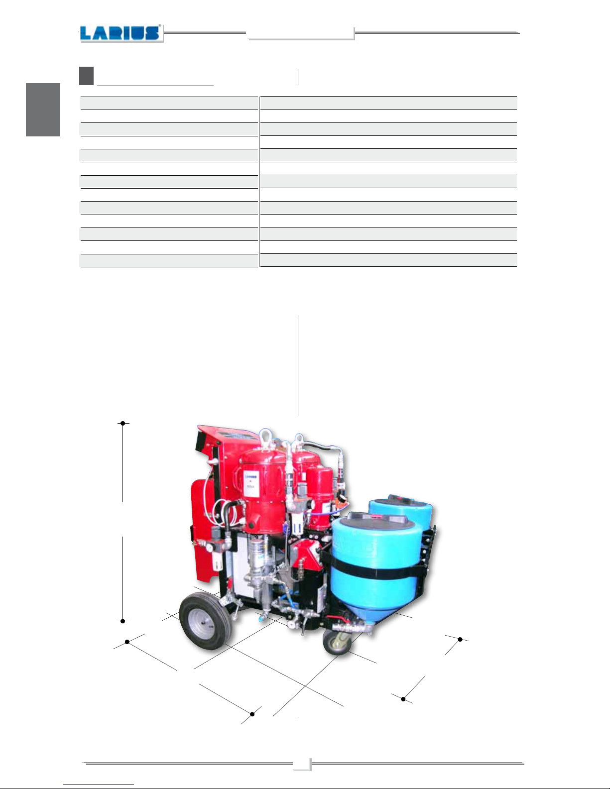
The LARIUS NOVA MIX 2K is a bi-component mixing machine.
It therefore provides for the dosage, mixture and application of
bi-component products.
This machine allows the user to work in high pressure with manual
or automatic spray-guns.
The dosing and the mixing of the components are regulated by
an electronic control system. The hydraulic unit contains two
flowmeters which regulate the input of the two components into
the mixing lines. It is here, thanks to a static mixer, that the mixing
of the products takes place.
The machine is made up of 4 main units:
•
The pump for the components unit
•
The hydraulic mixing unit
•
The command and control unit
•
Equipment supply
ADVANTAGES OF USING THE LARIUS MIX 2K
•
Increased product savings and consequent waste disposal
savings.
•
“Ecological” painting: performed in complete respect for the
working and external environment – Quick drying (even without
a drying oven).
•
High quality finish – Less use of paint thinners during cleaning
phases.
•
Increased resistance with respect to mono-component paints.
•
A product mixed at the moment is easier to lay.
•
Low solvent consumption for high dry residue of 2-component
paint.
•
Easy integration in workplace.
•
Alarm signals in the event of malfunction.
•
Easy and quick cleaning.
•
The operator manually mixes paints, catalysts, solvents.
•
Paint dries rapidly, even without oven.
•
Powers multiple manual-automatic guns simultaneously.
•
Only authorised personnel can set machine parameters.
Fields of application: Generic metalworking, Woodworking
and Furnishings, Aerospace industry, Plastics, Bicycles and motorcycles, Automobile components, Machines, Painting of furniture,
Varnishing, Emulsion painting.
Treatable products:
•
Low, medium and high viscosity products.
•
Water- and solvent-based products.
•
2-component epoxy paints and primers.
•
2-component polyurethane paints and primers.
•
2-component high solid
4
NOVA MIX 2K
English
B
•
Pot-Life time alarm.
•
Measuring and electronic control of flow and consumption.
•
Electronic control of dosage (the control system is not in contact
with the product).
•
Material in contact with the fluid in stainless steel or winc-coated
blows.
•
Trolley to facilitate movement.
•
50-litre gravity tank, equipped with an anti-splash cover. made
from non-stick materials ensuring quick and easy cleaning after
use.
•
Air Electric Generator allows operation with only the pneumatic
feed. Equipped with a battery buffer, the turbine works for 1/5
of the total operation time.
•
Larius heater up to 90°:increases the fluidity of the paint without
the use of solvents, increase the thickness of the protective film
and improves the finishing.
Bi-component water-soluble paints – bi-component solvent paints
Min 1:1 - Max 30:1 decimals included
Max 14 lt/min
400 bar
1%
7 bar
230 V 50 Hz
min. 5°C max. 50°C
74 dB
320 Kg
1000 mm
1300 mm
1480 mm
* Based on the characteristics of the paint to be used, the air-pressure supply and the mixing ratio.
** Temperatures refer to the machine, check the data sheets of the products as well.
TECHNICAL DATA
Varnish compatibility
Mixing ratio % in volume
Maximum capacity of mixed product (*)
Max working pressure
Measurement precision
Max intake pressure air
Electrical power supply
Machine working temperature (**)
Sound pressure level
Weight
Width (A)
Lenght (B)
Height (C)
B
A
C
5
NOVA MIX 2K
English
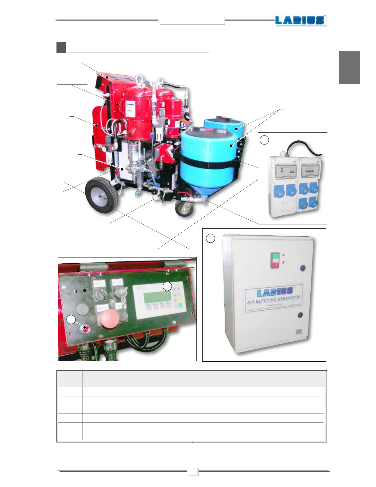
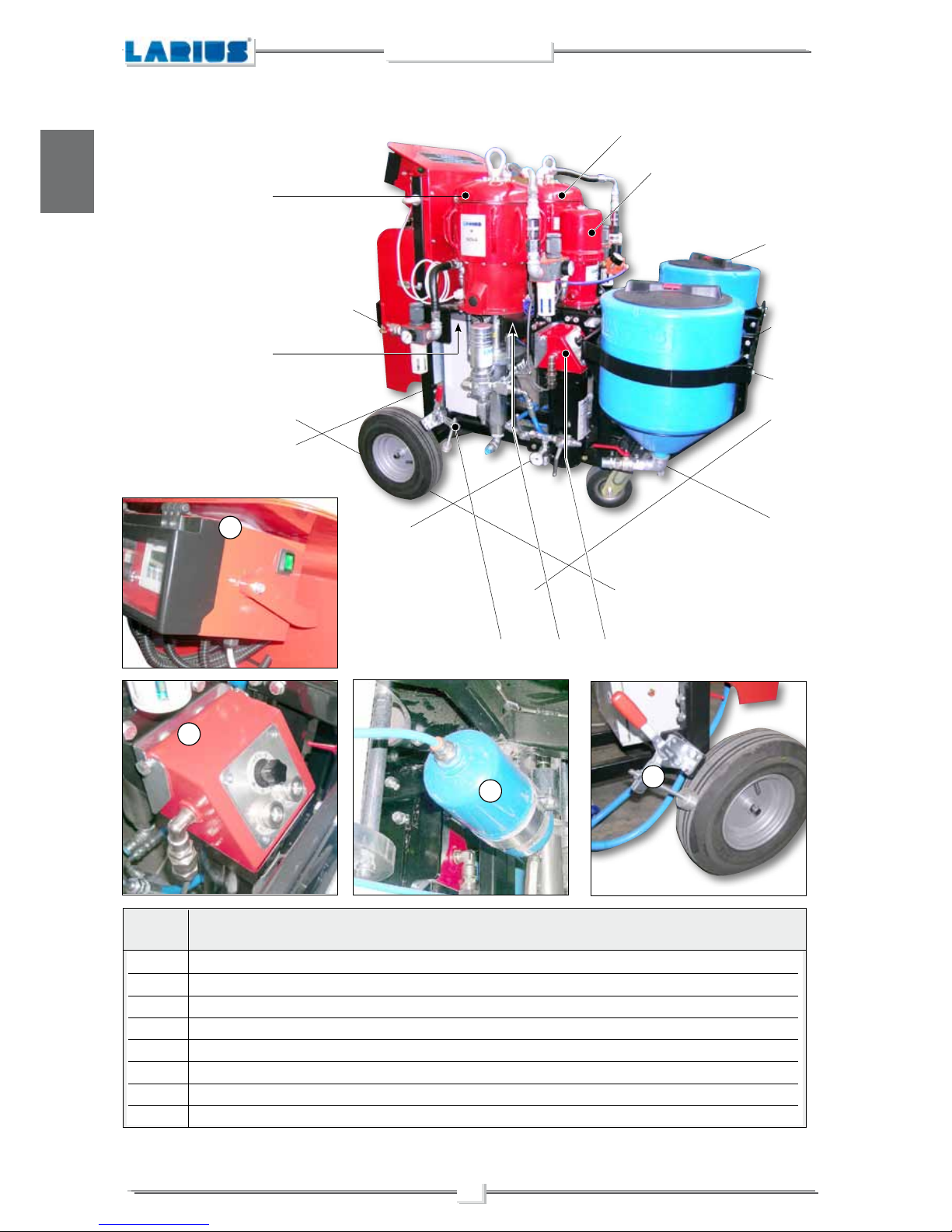
C
1
Electronic panel
2
Electro-pneumatic unit
3
A-B components tanks
4
Visual alarm device located on the control panel
5
Power supply panel, electric/pneumatic version
6
Electric generator for pneumatic only version
POS. DESCRIPTION
DESCRIPTION OF THE EQUIPMENT
ANTIFREEZE
SYSTEM
6
1
4
5
2
3
1 - 4
5 - 6
6
NOVA MIX 2K
English
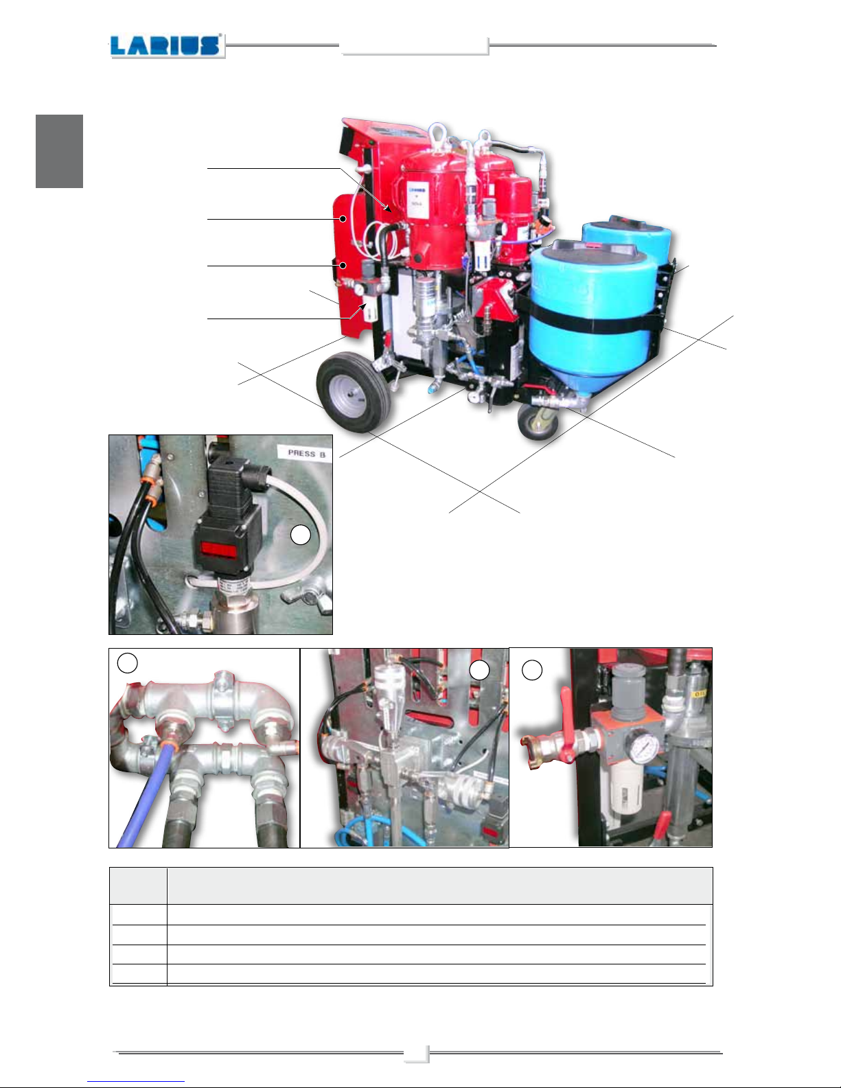
7
Mixing head
8
Pressure digital viewer
9
Air filter/regulator
10
Air distribution collectors
POS. DESCRIPTION
8
10
7 9
10
8
7
9
7
NOVA MIX 2K
English
11 Auxiliary air distribution group
12 Air regulators for pump supply
13 Eye bolts for lifting - Note: (Do not use the eye bolts of the pumps to lift the machine)
14 Product filter
POS. DESCRIPTION
1313
13
12
12
14
11
14
13
12 13 1113
8
NOVA MIX 2K
English
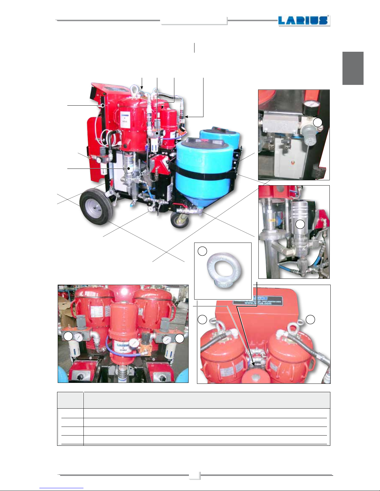
15
Wheel brake
16
Washing pump
17
Air accumulation lung for electro-pneumatic group
18
Component heater A-B
19
Encoder for dosage of components A-B
20
Component pump A
21
Component pump B
22 Comand box
POS. DESCRIPTION
22
18
17
15
19
21
15 17
18
20
16
9
NOVA MIX 2K
English
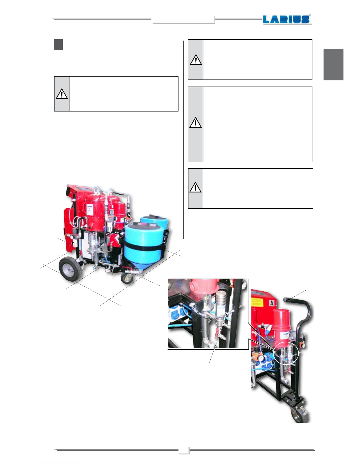
D
Before lifting the machine, check the position of
the handle (D1).
If necessary, remove the handle or secure it to the
structure of the machine (D2)
TRANSPORT AND UNPACKING
•
The packed parts should be handled as indicated in the
symbols and markings on the outside of the packing.
LIFTING POINTS
There are no precise lifting points for lifting the machine in its
entirety.
In order to determine the most appropriate lifting points, refer to
the geometric characteristics of the machine itself.
Make sure that the pull position of the
synthetic fibre belt does not interfere with
any of the machine’s fragile elements
which could be damaged from the tension
produced during lifting.
All of the operations described in this paragraph
must be performed by qualified technicians who
have been trained for the task required.
Before lifting and moving the machine, make sure
that the equipment being utilised is of an adequate
size to bear the weight of the machine and its
components.
Do not stand beneath or near the machine while
it is being lifted.
Lift the machine slowly and check that it is properly
balanced with respect to its centre of gravity.
While being moved, the machine should only be
lifted to the minimum necessary height.
•
Before installing the equipment, ensure that the area to
be used is large enough for such purposes, is properly
lit and has a clean, smooth floor surface.
D1
D2
10
NOVA MIX 2K
English
E
SAFETY RULES
•
THE EMPLOYER SHALL TRAIN ITS EMPLOYEES ABOUT
ALL THOSE RISKS STEMMING FROM ACCIDENTS, ABOUT
THE USE OF SAFETY DEVICES FOR THEIR OWN SAFETY
AND ABOUT THE GENERAL RULES FOR ACCIDENT
PREVENTION IN COMPLIANCE WITH INTERNATIONAL
REGULATIONS AND WITH THE LAWS OF THE COUNTRY
WHERE THE PLANT IS USED.
•
THE BEHAVIOUR OF THE EMPLOYEES SHALL STRICTLY
COMPLY WITH THE ACCIDENT PREVENTION AND ALSO
ENVIRONMENTAL REGULATIONS IN FORCE IN THE
COUNTRY WHERE THE PLANT IS INSTALLED AND USED.
The user is responsible for the operations of
unloading and handling and should use the
maximum care so as not to damage the individual
parts or injure anyone.
To perform the unloading operation, use only
qualified and trained personnel (truck and crane
operators, etc.) and also suitable hoisting equipment
for the weight of the installation or its parts. Follow
carefully all the safety rules.
The personnel must be equipped with the necessary
safety clothing.
•
The manufacturer will not be responsible for the unloading
operations and transport to the workplace of the machine.
•
Check the packing is undamaged on receipt of the equi-
pment. Unpack the machine and verify if there has been
any damage due to transportation.
In case of damage, call immediately LARIUS and the
Shipping Agent.
All the notices about possible damage or anomalies must
arrive timely within 8 days at least from the date of receipt
of the plant through Registered Letter to the Shipping
Agent and to LARIUS.
The disposal of packaging materials is a customer’s
competence and must be performed in accordance
with the regulations in force in the country where
the plant is installed and used
.
It is nevertheless sound practice to recycle packaging materials in an environment-friendly manner
as much as possible.
•
KEEP YOUR WORK PLACE CLEAN AND TIDY. DISORDER
WHERE YOU ARE WORKING CREATES A POTENTIAL
RISK OF ACCIDENTS.
•
ALWAYS KEEP PROPER BALANCE AVOIDING UNUSUAL
STANCE.
•
BEFORE USING THE TOOL, ENSURE THERE ARE NOT
DAMAGED PARTS AND THE MACHINE CAN WORK PROPERLY.
•
ALWAYS FOLLOW THE INSTRUCTIONS ABOUT SAFETY
AND THE REGULATIONS IN FORCE.
•
KEEP THOSE WHO ARE NOT RESPONSIBLE FOR THE
EQUIPMENT OUT OF THE WORK AREA..
•
NEVER EXCEED THE MAXIMUM WORKING PRESSURE
INDICATED.
•
NEVER POINT THE SPRAY GUN AT YOURSELVES OR AT
OTHER PEOPLE. THE CONTACT WITH THE CASTING CAN
CAUSE SERIOUS INJURIES.
•
IN CASE OF INJURIES CAUSED BY THE GUN CASTING,
SEEK IMMEDIATE MEDICAL ADVICE SPECIFYING THE
TYPE OF THE PRODUCT INJECTED. NEVER UNDERVALUE A WOUND CAUSED BY THE INJECTION OF A FLUID.
•
ALWAYS DISCONNECT THE SUPPLY AND RELEASE THE
PRESSURE IN THE CIRCUIT BEFORE PERFORMING ANY
CHECK OR PART REPLACEMENT OF THE EQUIPMENT.
•
NEVER MODIFY ANY PART IN THE EQUIPMENT. CHECK
REGULARLY THE COMPONENTS OF THE SYSTEM.
REPLACE THE PARTS DAMAGED OR WORN.
•
TIGHTEN AND CHECK ALL THE FITTINGS FOR CONNEC-
TION BETWEEN PUMP, FLEXIBLE HOSE AND SPRAY GUN
BEFORE USING THE EQUIPMENT.
•
ALWAYS USE THE FLEXIBLE HOSE SUPPLIED WITH
STANDARD KIT. THE USE OF ANY ACCESSORIES OR
TOOLING OTHER THAN THOSE RECOMMENDED IN
THIS MANUAL, MAY CAUSE DAMAGE OR INJURE THE
OPERATOR.
•
THE FLUID CONTAINED IN THE FLEXIBLE HOSE CAN
BE VERY DANGEROUS. HANDLE THE FLEXIBLE HOSE
CAREFULLY. DO NOT PULL THE FLEXIBLE HOSE TO
MOVE THE EQUIPMENT. NEVER USE A DAMAGED OR
A REPAIRED FLEXIBLE HOSE.
Read carefully and entirely the following instructions before using the product.
Please save these instructions in a safe place.
The unauthorised tampering/replacement of one
or more parts composing the machine, the use
of accessories, tools, expendable materials other
than those recommended by the manufacturer can
be a danger of accident.
The manufacturer will be relieved from tort and
criminal liability.
•
NEVER SPRAY OVER FLAMMABLE PRODUCTS OR SOL-
VENTS IN CLOSED PLACES.
•
NEVER USE THE TOOLING IN PRESENCE OF POTEN-
TIALLY EXPLOSIVE GAS.
The high speed of travel of the product in the hose
can create static electricity through discharges
and sparks. The pump is earthed through the earth
with sliding chain.
11
NOVA MIX 2K
English
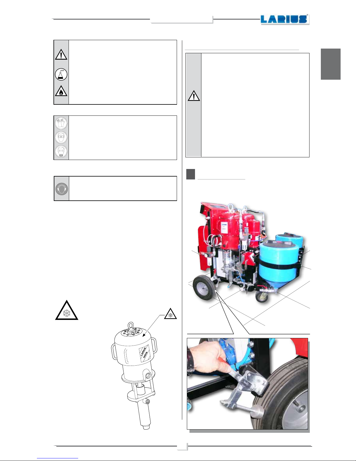
F
Stop the machine as shown in the picture below.
Always check the product is compatible with
the materials composing the equipment (pump,
spray gun, flexible hose and accessories) with
which it can come into contact. Never use paints
or solvents containing halogen hydrocarbons (as
the methylene chloride).
If these products come into contact with aluminium
parts can provoke dangerous chemical reactions
with risk of corrosion and explosion.
IF THE PRODUCT TO BE USED IS TOXIC,
AVOID INHALATION AND CONTACT BY USING
PROTE CTIO N GL OV ES, GOGG LES AND
PROPER FACE SHIELDS.
TAKE PROPER SAFETY MEASURES FOR THE
PROTECTION OF HEARING IN CASE OF WORK
NEAR THE PLANT.
•
MAKE SURE YOU KNOW HOW TO SHUT OFF THE
EQUIPMENT IF NECESSARY. INEXPERIENCED USERS
SHOULD BE TRAINED TO SAFELY AND PROPERLY USE
THE MACHINE BEFORE OPERATING IT.
•
KEEP UNAUTHORISED PERSONNEL AWAY FROM THE
MACHINE, ABOVE ALL IF A TOXIC PRODUCT IS BEING
UTILISED.
•
IF NECESSARY, USE WARNING SIGNS TO KEEP ANYONE
PRESENT AT A SAFE DISTANCE.
•
MAKE SURE THAT THERE IS ALWAYS SOMEONE WITHIN
SHOUTING DISTANCE IN CASE AN ACCIDENT SHOULD
OCCUR.
SETTING-UP
The machine is equipped with
an anti-freeze system
that allows it
to work even at very low
te mperatu re s. H ow ev er,
after a few mi nu tes of
operati o n , t h e upper
metal outer surface cools
dramatically.
Avoid touching the area
indicated.
Co ntact of th e sk in with
th e low-t em peratur e ar ea
may cause frostbite. Common
working clothes and leather
gloves p rovide a d e q u ate
protection.
The conditions of guarantee do not apply in the
following situations:
- improper washing and cleaning of components
causing malfunction, wear or damage to the
equipment or any of its parts;
- improper use of the equipment;
- use that does not conform with applicable national
legislation;
- incorrect or faulty installation;
- modifications, interventions and maintenance that
have not been authorised by the manufacturer;
- use of non-original spare parts or parts that do
not correspond to the specific model;
- total or partial non-compliance with the instructions provided.
CONDITIONS OF GUARANTEE
12
NOVA MIX 2K
English
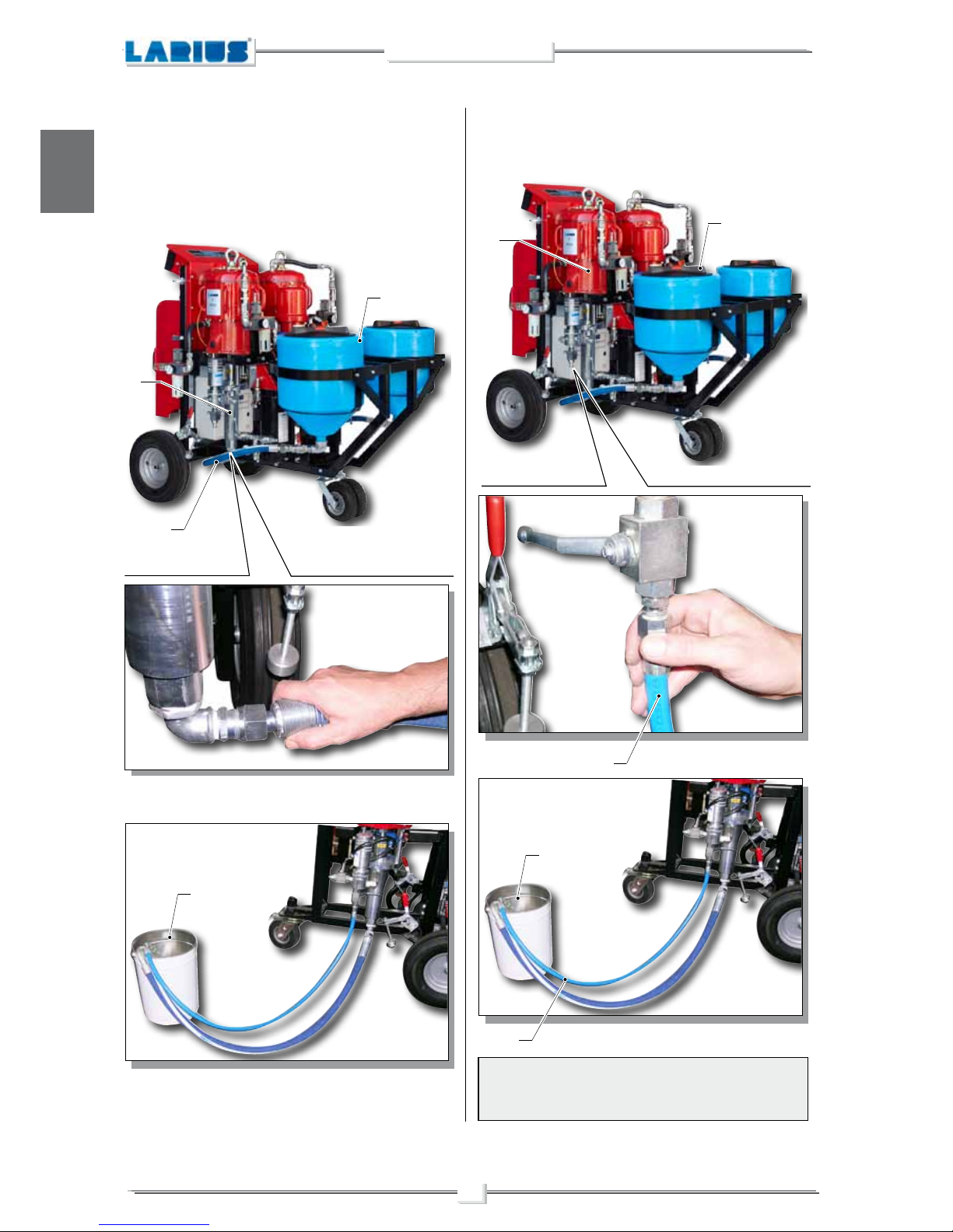
PRODUCT PIPING CONNECTION
•
A Product suction
Connect the flexible product suction tube (F1) to the pump
(F2) and the tank (F3), or to your product container (F4).
•
B Recirculation
Connect the flexible recirculation tube (F5) between the pump
(F6) and the upper part of the tank (F7), or to your product
container (F4).
NOTE
The procedures A and B must be carried out on both the pumps
and tanks.
F7
F5
F6
F5
F3
F1
F2
F4
F4
13
NOVA MIX 2K
English
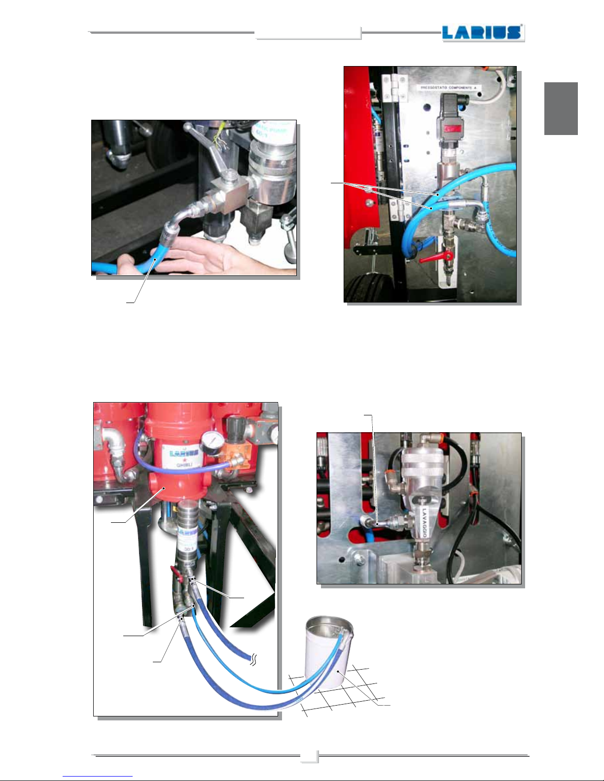
•
C Pump/Pressure switch control
Check the two flexible product delivery hoses (F8) between
the pump of component (A) and the pump of component (B)
and the related mixing group (A) and (B)
F8
•
D Washing connection
Connect the suction tube (F11) to the pump (F13).
Connect the recirculation tube (F9) to the pump (F13).
Immerse the two tubes (F11) (F9) into the container (F12) of
washing liquid.
Connect the delivery hose (F14) to the mixing group (F10) for
washing.
F10
F11
F9
F12
F13
F14
F8
14
NOVA MIX 2K
English
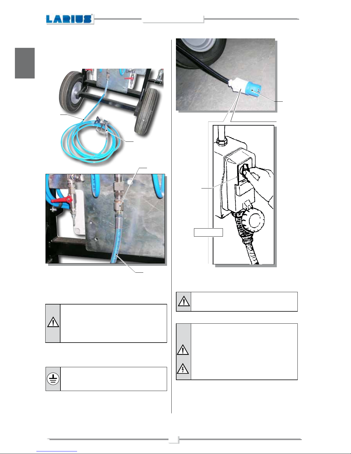
•
E Gun piping connection
Connect the tube (F15) of the gun (F16) to the connector of
the mixing group (F17).
F15
F16
F15
F17
Make sure that the connections are tightly sealed. It is recommended to use two wrenches to tighten them.
The machine is equipped with a connection plug (F18) that is to
be connected to the main switch (F19).
F18
F19
220V - 50Hz
CHECK ON POWER SUPPLY
Make sure that the system is properly grounded.
Use an electrical plug which guarantees the proper
grounding of the system.
DO NOT use thread pastes upon the connections.
It is recommended to use the tubes which have been
supplied along with the machine.
NEVER use a damaged or repaired flexible tube.
The machine requires a 220V alternating current
power supply.
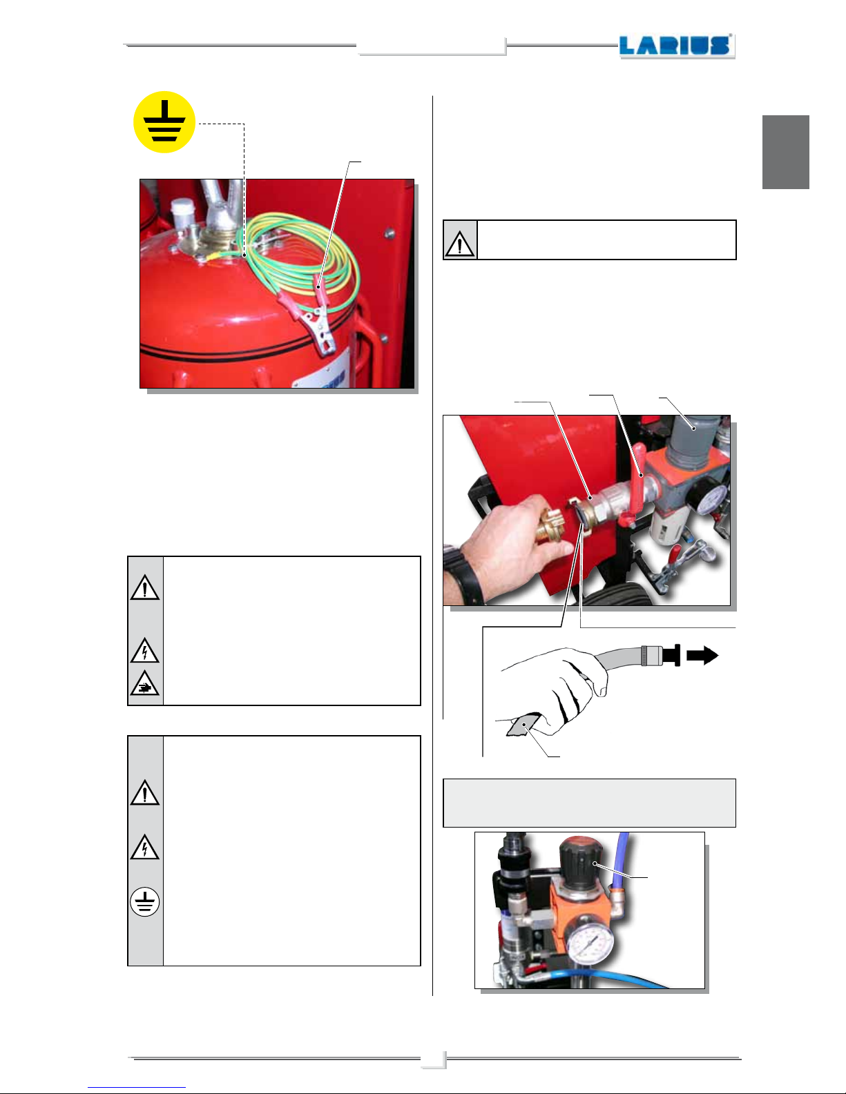
LARIUS NOVA MIX 2K equipment is fitted with an additional
external earth cable that is connected to the stem on the pump
unit be means of a specific clamp (F20), in order to protect the
operator against any risk of static or electric shock.
Should anyone use an extension cable between
the tooling and the socket, it must have the same
characteristics as the cable supplied (minimum
diameter of the wire 4 mm
2
) with a maximum length of 50 mt. Higher lengths and lower diameters
can provoke excessive voltage falls and also an
anomalous working of the equipment.
15
NOVA MIX 2K
English
CONNECTING THE EQUIPMENT TO THE PNEUMATIC LINE
☞
NOTE
Adjust all regulators to the working pressure (F25).
To avoid electric shock when disassembling or checking the electronic equipment, wait 5 minutes after having disconnected the
power supply cable, so that the electricity stored in the condensers
while working can be dissipated.
Also check the condition of the earth cable to avoid any risk of shock.
Before carrying out any checks on the machine
(maintenance, cleaning, or replacing parts) switch
off the machine and wait until it has stopped
altogether.
While checking stay away from electrical or moving
parts to avoid any risk of shock or crushing of hands.
WARNING :
•
DO NOT modify the plug for the earth socket
in any way.
•
ONLY use electrical connections that are
earthed.
•
Make sure that any earth extension cords are
in good condition.
•
ONLY use three-core extension cables.
•
Avoid direct contact with the rain. Keep the
equipment in a dry place.
The machine must be connected to the compressed air feeding
system, which is necessary for the pneumatic interlocking.
The connection must be carried out in the following way:
•
Connect the air feeding pipe (F21) to the joint (F22).
It is advisable to install an on-off valve on the frontal
part of the machine
Make sure that the air line to be connected to the machine is
capable of constantly providing pressure at 7 bar.
Before opening the air line, turn the ball valve (F23) on the general
regulator (F24) to its closed position.
After having opened the machine's air supply, open the ball valve
completely (F23) and set the regulator to maximum (F24).
F20
F24
F23
F21
F22
F25
16
NOVA MIX 2K
English
WASHING OF THE NEW EQUIPMENT
•
The machine has been tested at the manufacturer’s facilities.
Perform a wash cycle with the paint thinner before suctioning
any product.
•
Place the suction tubes in the solvent containers or else pour
solvent into the gravity tanks.
•
Open only the recirculation valves.
•
Circulate the solvent within the output pumps.
•
Close recirculation valve.
•
Open the delivery valves, leaving the related discharges
closed.
•
start an automatic working cycle and to circulate the solvent
until it emerges clean machine.
•
Stop the automatic work cycle and activate a wash cycle.
☞
NOTE
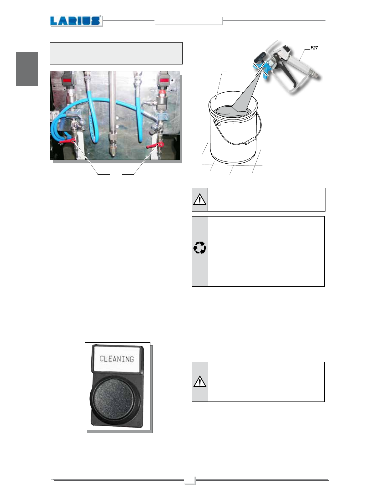
Close the discharge valves (F26).
PREPARING THE PRODUCT
Make sure the product to be used is compatible
with the materials employed for manufacturing the
equipment (stainless steel and aluminium).
Because of that, please contact the supplier of the
product
.
Never use products containing halogen hydrocarbons (as
methylene chloride). If these products come into contact with
aluminium parts of the equipment, can provoke dangerous
chemical reactions with risk of explosion.
In order to prepare the products (i.e. for dilution), refer to the
supplier’s data sheets.
Absolutely avoid to spray solvents indoors.
For disposing of the washing liquid, see the
requirements laid down in the Standards in force
in the country in which the equipment is used and
act accordingly.
The Client is solely responsible for any irregular
action taken before, during, or after disposing of
washing liquid, or in interpreting and applying the
current Standards in this regard.
•
Now the machine is ready.
When water-based paint has been used, in addition to washing
using the cleaning liquid, we recommend washing with soapy
water and then clean water.
•
During the wash cycle, hold the spray-gun (F27) over a
container (F28) and keep the trigger pulled.
F26
F27
F28
17
NOVA MIX 2K
English
G1
G2
G3
G5
G5
G7
G8
OPEN
G7
- G8
CLOSE
G9
G10
G7 - G8
G9 - G10
OPEN
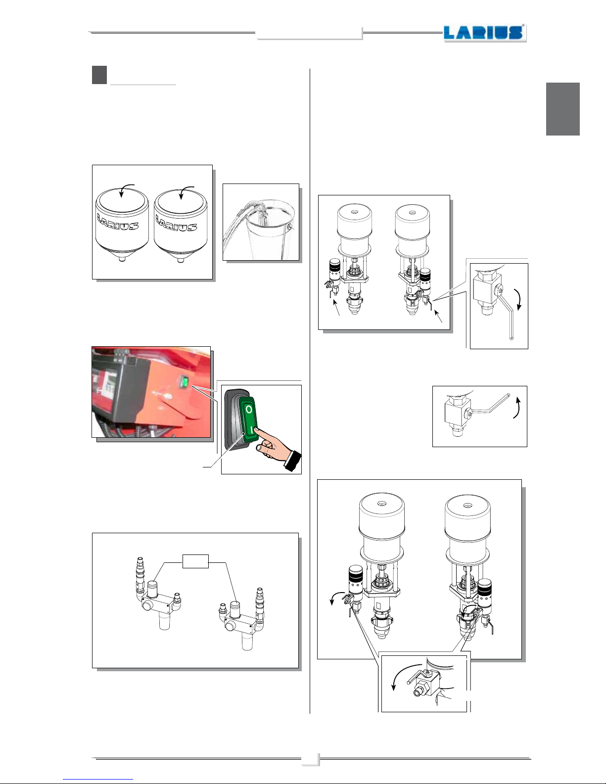
STARTING UP AND CHARGING THE MACHINE
1. Fill the tanks (G1) and (G2) with the materials necessary
for processing. For versions without tanks, directly introduce
floaters into the containers (G3).
G
2. After connecting the machine to the power, press the side
switch (G4) located on the control panel in position “I".
3. Power the pumps with compressed air and set the two regu-
lators to minimum (G5) and (G6).
4. Open the recirculation valves (G7) and (G8) allowing the
product to begin recirculation.
☞
NOTE
If you are not sure that the first part of the product is properly
cleaned, discharge the first part, which starts to recirculate outside
the tanks, to avoid contaminating the clean product.
5. Close the recirculation valves (G7) and (G8).
WORKING
6. Open the delivery valves (G9) and (G10).
G4
MIN
18
NOVA MIX 2K
English
G12
G12
OK
Make sure that the values are equal, within a certain tolerance
(the tolerance may vary in relation to the working pressure with
which the machine will normally be used).
Check for any machine alarms (visible on page F4). If present,
consult the “alarms” page where the various modes of resolving
alarm states are listed.
If the machine does not have any alarms active, proceed with the
setting of the machine’s parameters (see the relative chapter).
Turn the selector (G15) to the AUTOMATIC position.
7. Open the manual discharge valves (G11) and wait for the
clean product to come out.
This operation allows for the elimination of any eventual air
bubbles within the circuit.
8. Close the manual discharge valves (G11).
9. Bring the pumps to the desired pressure and begin working
(G12).
Wait for the flexible spray-gun tube to load (wait for the valves
(G11) to shut off automatically).
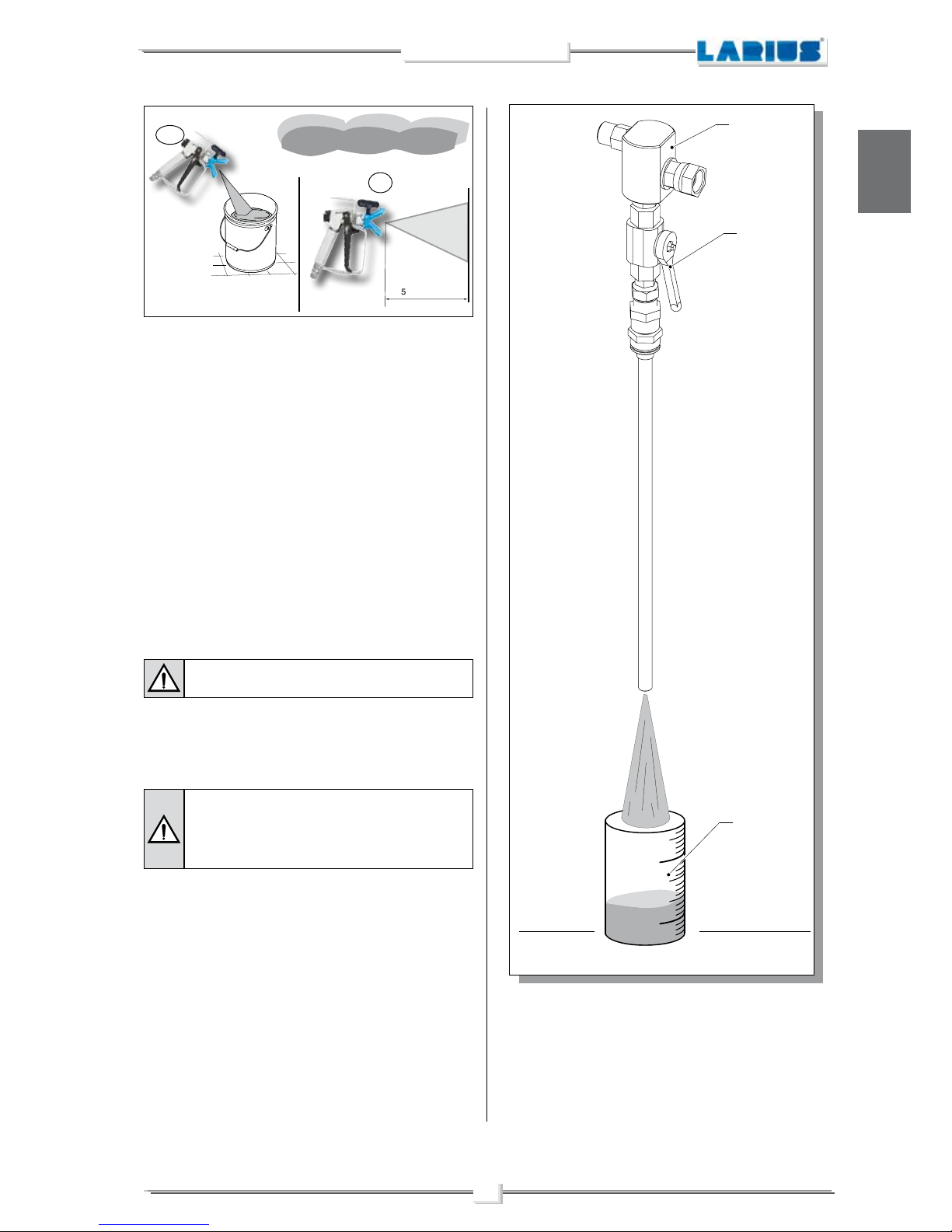
Before painting, spray the product into a container (G16) or into
a part of the cab (G17) dedicated to purging, while keeping the
spray-gun at a constant distance from the surface (500-700mm).
Use this same distance for all other applications.
This procedure will allow the user to perform any necessary
adjustmen ts, such as: widening the spray, atomising-air
adjustment, adjustment of the various working pressures, etc.
Check the circuit’s internal pressure by checking the values indicated on the two displays (G13) located above the flowmeters (G14).
G11
G11
G15
G14
G13
G11
G11
19
NOVA MIX 2K
English
500-700 mm
Once this purging phase has been completed, the operator can
proceed with normal working operations.
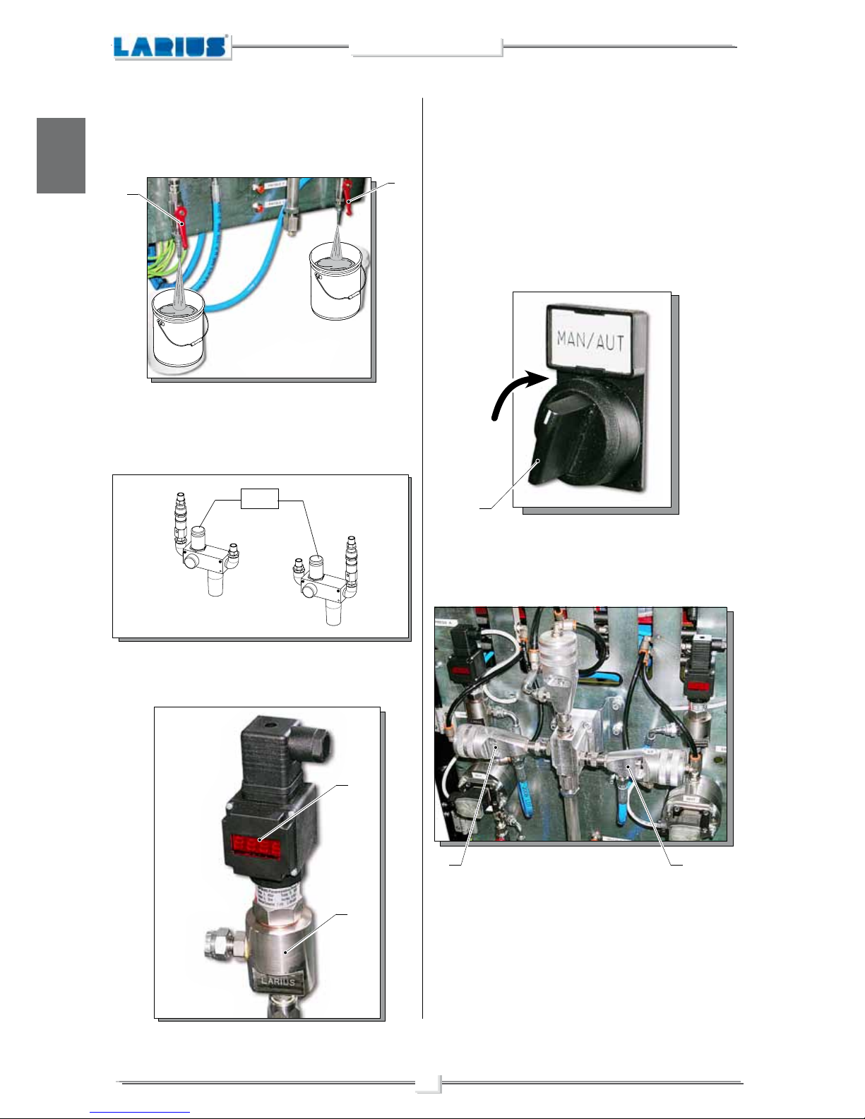
PROCEDURE FOR CHECKING COMPONENT
DOSAGE
These mixing blocks have been designed to allow the operator
using the LARIUS NOVA MIX 2K to check that the mixing ratio
of the two components is correct.
The operator must perform the following procedure in order to
check the quantities of the two components just before they are
mixed:
•
Mount the component tapping blocks (G18).
•
Open the valves (G19) and set the tapping cycle in order to
check the dosage of the components.
The machine must not be pressurized.
•
By positioning the 2 containers (G20) in correspondence
to the 2 outlets, the operator can check the actual amounts
dispensed by the machine.
During the normal tapping phase, the valves (G19)
must always be open.
During the normal working phase, the two blocks
(G18) must not be mounted.
G18
G19
G20
G16
G17
20
NOVA MIX 2K
English
recirculation
recirculation
A
LARIUS NOVA MIX
OUTPUT GUN
PRODUCT A
CATALYSER B
GHIBLI
WASH
recirculation
B
L
A
B
L
FLOW
Flow diagram for the 2 components
Flow diagram for the wash fluid
•
The fluid is drawn into the system by the wash pump.
•
This pump ( GHIBLI ) filters the wash fluid before sending it
into the machine.
•
The wash fluid through the nozzle located on the mixing block.
From there, they proceed to clean out the mixing line as well
as the tube containing the mixture of the 2 components.
Product tank
Wash fluid tank
Catalyser tank
Pump
Pump
Pump
Flow diagram for the 2 components
•
The components are drawn from either external tanks or from
gravity tanks.
•
The 2 pumps ( NOVA ) send the components to the NOVA
MIX 2K machine.
•
In the NOVA MIX, the components flow through the pressure
gauge and the mixing group.
•
The components then enter their respective nozzles located
on the mixing block. Based on the settings provided by the
machine, these regulate the passage of the materials in order
to obtain a proper mixture.
• Along the length of the block and of the mixing tube, the 2
components are mixed together until they arrive perfectly
mixed at the spray-gun’s outlet.
- It is recommended to ALWAYS keep the catalyser in part B of the circuit, both in the machine
as well as in the flow pump, and to use part A
exclusively for the product.
- Make sure that the wash fluid, whether water
or solvent based, is compatible with the two
components being utilized.
- If one or both of the components is changed,
perform a “complete” washing cycle in the NOVA
MIX 2K system.

21
NOVA MIX 2K
English
H7
H7
H4
H
WASHING
Empty any product present inside the machine.
For example, after complete washing (the machine has sucked
up solvent).
•
Remove the floaters (H1) from the drums (H2) or unscrew and
detach the supply tube (H3) from the pumps, to be sure that the
pumps can no longer suck up the products.
H2
H1
•
Set the pressure of the pumps (H4) to the minimum for them to
work, using the regulators on the pumps themselves.
•
Leave the delivery valves open (H5) and open the recirculation
valves as well (H6).
H5
H6
•
Open the two relief valves located under the digital pressure
gauges (H7).
H3
MAINTENANCE

22
NOVA MIX 2K
English
H8
H9
H10
H13
H13
H13
•
In "manual" mode (H8) open the 3 solenoid valves and “spray”
with the gun to release the entire product inside (H9).
DECOMPRESSION
Discharge all pressure before servicing the machine as indicated:
•
close the ball valve (H10) located at the machine inlet
•
open the 3 recirculation valves (H11) (Pump A and B, washing)
H11
H12
H12
•
Open the two relief valves located under the 2 digital pressure
gauges (H12)
•
manually open the three solenoid valves (Ev A, Ev B, Ev L) and
spray in such a way as to ensure that the residual pressure is
released
•
discharge and reset all the regulators (H13) present on the
machine (make sure that the pressures shown on the related
pressure gauges are at "0").

23
NOVA MIX 2K
English
H14
H17
H18
H19
H15
FILTER CLEANING
In case of obstruction or spraying difficulty, inspect the filter during
the work phase:
•
open the slide valve (H14) of the pump you want to inspect to
cut the air supply and discharge the pressure.
•
if it is a "Nova pump", close the delivery valve (H15)
H16
Slowly open the recirculation valve (H16).
•
Wait for the filter tank to empty (H17)
•
Open the filter tank to inspect it as indicated below:
- unscrew the filter (H18) using a suitable spanner (H19)
H20
- remove the cover (H20)

24
NOVA MIX 2K
English
H24
•
check periodically (and whenever the pump is started after
a long period of inactivity) that the press ring seals not come
loose, causing the leakage.
Use the key provided (Ref. 11504). The nut must be tightened to
prevent leaks but not too much in order not to cause the seizure
of the pump piston and the wear of the seals. If it persists loss
of product to replace the seals.
Crown
oil filler
Cup grease port
Key
Ref. 11504
Always close the compressed air supply and
discharge the pressure in the system before
inspecting or carrying out any maintenance
work on the pump.
H21
- unscrew the filter (H21) with the spanner (H22)
H22
H23
- remove the filter (H23) and proceed to cleaning with the wa-
shing liquid.
GASKET PACK REGULATION
When necessary, pull the gasket pack on the pump as indicated:
•
open the slide valve (H24) to cut and release the air supply
- open the recirculation valve (H25)
H25

25
NOVA MIX 2K
English
•
Keep the bucket of lubricant liquid full (compatible with the
product being used) in order to prevent the product from drying
on the gun shaft.
H26
H27
H27
•
open the two relief valves located on the 2 digital pressure
gauges (H27) and open the recirculation valves (H28).
H28
Close the machine’s intake taps (H26).
CLEANING AFTER WORK ACTIVITIES
Make sure that the machine is not pressurised
before performing any operations which require
the closure or the connection of any machine
component (filter checks, seal closure, etc.).
In “MANUAL OPERATING MODE”, use the electrovalves on the
operator’s panel to make sure that there is no pressure inside
the mixing block. Open and close the three valves on the mixing
block a few times (see the page regarding “manual controls” in
the manual).
ROUTINE MAINTENANCE
Remember to perform a wash cycle before any lengthy periods
of disuse. Periods of disuse can be judged according to the POT
LIFE of the components which are being utilised.
The manufacturer recommends for a wash cycle to be performed
at the end of every working day.
PERIODIC MAINTENANCE (weekly)
Check the machine’s intake filters.
Perform this same check upon all of the filters.
Before opening the filter, remove the filter's tank
(H29) in accordance with the following indications:
- Close the delivery tap (H30);
- Open the filter's drain tap (H28);
This operation will drain any pressure contained
within the filter.
Inspect the unit and make sure that the filter is
not clogged.
H30
H29
H28

26
NOVA MIX 2K
English
SIEMENS
HELP
ESC
ACK
ENTER
SHIFT
TAB
INSDEL
+ / -
SIMATIC PANEL
F3
F4
F2
F1
TAB
+ / -
TAB
INSDEL
ENTER
ENTER
I
OPERATOR PANEL
The explanations provided must be read by any personnel who
will operate the system.
If the system functions in a different manner with
respect to the information which has been inserted,
the user is advised to communicate the event to
the manufacturer so that a technician may verify
the program which has been loaded onto the PLC.
Use the 4 arrow buttons to the right of the display to navigate
within the selected screen.
Procedure for selecting a field to modify:
•
use the arrow buttons to select the desired field ;
•
activate the field by pressing ;
•
modify the set value with the and arrows;
•
press the button to confirm the entry.
OPERATING PANEL
The operating panel is connected to the system and is used for:
•
inserting and viewing process variables
;
•
viewing alarms and signals in order for the operator to easily
identify them while the system is in function
;
•
selecting the desired function in manual mode
.
CONTROL PANEL
The Control panel (I1) is used in conjunction with the Operating
Panel by the user to control machine function, to select the cycles
(manual, automatic) and functionalities, as well as for immediately
viewing the system’s functional status.
The light on the panel indicates whether any alarms are active.
ALARM CHECKS
The PLC reacts in the following manner to every alarm event:
•
The red light (I2) installed upon the control panel flashes;
•
The operating panel displays the text which corresponds to the
alarm.
The functionality in question which has generated the alarm is
blocked until the anomaly has been fixed.
To cancel the alarm, do the following:
•
resolve the situation which caused the alarm;
•
press the F4 button on the alarm screen to reset the alarm
;
•
press the ACK alarms button to remove the alarm from the panel;
The system will not allow an alarm to be reset if the situation which
caused the alarm has not been resolved.
Some alarms are automatically reset once the situation which
caused the alarm has been resolved.
POWER STATUS
The power status is indicated
by a green light located on the
system’s ON/OFF selector.
I1
I2

27
NOVA MIX 2K
English
J
LOCKING SELECTOR
In order to prevent unauthorised personnel from modifying the
machine’s settings, a locking safety selector (I3) has been installed
upon the panel.
The selector can be turned:
•
to the right in order to allow for the machine’s settings to be
modified.
•
to the left in order to protect the machine’s settings with a secret
password.
The machine is furnished with two keys (one spare key for use in
the event that the regular key is lost).
The safety keys should be entrusted to a person who is authorised
to modify the machine’s settings and data.
Before activating any functions in manual mode,
the operator must make sure that the workplace
is free of obstacles in order to avoid damage to
people, property and/or parts of the machine.
The manual controls must only be utilised by
authorised personnel who are familiar with the
system’s functionalities.
The manual cycle keeps most of the interlocking
parts disabled. It is therefore the operator who
must activate or deactivate each single function.
The operator will be responsible for the correct use
the system’s functions in order to avoid damaging
or blocking the lines.
During automatic function, the selection of the
manual cycle will provoke the arrest of all of the
system's functions and the cancellation of the
manual cycle.
The operator can activate manual cycle functionality in the
following manner:
•
make sure that nobody is within the working area;
•
turn the manual-automatic selector (J1) to the manual position.
MANUAL MODE
Manual operating mode allows the user to control all of the
system’s available functionalities as well as the wash function:
•
manual controls
•
wash cycle
•
tapping cycle (when necessary)
START-UP PROCEDURES
The system has two operating modes:
•
MANUAL MODE
•
AUTOMATIC MODE
The operating mode can be selected using the 2-point selector
(J1) located on the control panel.
In order to activate the manual operating mode, the user must
turn the selector (J1) to the manual position.
I3
J1
J1

28
NOVA MIX 2K
English
SIEMENS
HELP
ESC
ACK
ENTER
SHIFT
TAB
INSDEL
+ / -
SIMATIC PANEL
F3
F4
F2
F1
Washing
T1 000
Manuals: Ev L 0
Ev A 0 Ev B 0
SIEMENS
HELP
ESC
ACK
ENTER
SHIFT
TAB
INSDEL
+ / -
SIMATIC PANEL
F3
F4
F2
F1
Washing
T1 000
Manuals: Ev L 0
Ev A 0 Ev B 0
SIEMENS
HELP
ESC
ACK
ENTER
SHIFT
TAB
INSDEL
+ / -
SIMATIC PANEL
F3
F4
F2
F1
Control settings
Pot life (min) 00
Enable tapping cycle 0
Number of tapping cycles
000 000
F2
The wash cycle can be activated while the selector is in the manual
position. In order to activate it, press the wash button located on
the control panel.
T1 000
Time "T1” must be set, opening the page with the F2 key. The
base of the time is in seconds.
Tapping cycle (when necessary)
Manual controls
Press the F2 button on the operating panel to access the manual
controls screen. Select the field for the desired valve and set the
value to 1. The valve will open automatically.
The valves are defined as follows:
- Ev L: wash electrovalve manual control
- Ev A: component A electrovalve manual control
- Ev B: component B electrovalve manual control
These three fields can be used to switch over/open every single
electrovalve while the selector
(J1)
is set to Manual.
Modify the field’s value to 0 or 1 in order to activate or deactivate
the relative electrovalve and to allow the selected component to
flow within the machine.
This function is necessary for performing a
complete wash of the entire system when the
two pumps have to be washed using two different
wash fluids (i.e. component A requires water to be
used as a wash fluid and the catalyser B requires
the use of a solvent).
This operation must also be performed when releasing pressure.
When a valve is opened in the absence of product, the pressure
contained within the mixing block is released.
Perform this operation for component A, component B and the
wash fluid as well (Ev A, Ev B, Ev L).
Wash cycle
J1
J1

29
NOVA MIX 2K
English
J2
SIEMENS
HELP
ESC
ACK
ENTER
SHIFT
TAB
INSDEL
+ / -
SIMATIC PANEL
F3
F4
F2
F1
General settings
Impulse count frequency 000
A/B Ratio 00 /00
AUTOMATIC MODE
The automatic cycle is used for regular working functionality.
In order to activate automatic mode functionality, the operator
must turn the selector(J1) to the automatic position.
The tapping cycle can be activated while the selector is in the
manual position. In order to activate it, set the "Enable tapping
cycle" value to "1" and set the Number of control cycles field to
the "number of tapping cycles" to be performed.
Once these values have been set, just turn the selector to the
automatic position and then back to the manual position. The
machine will perform the number of cycles requested.
To deactivate automatic mode functionality, just turn the selector
(J1) to the manual position.
When the automatic cycle is active, the program controls the
sequence of the valves for the two components and doses them
based on the requested ratio and based on the “impulse count
frequency” settings.
Just press the F1 button to access the “General Settings” screen.
The adjustment of the “impulse count frequency”
must be done in such a way so as to avoid high
frequencies which may not be supported by the
components.
TOTAL SHUTDOWN OF THE CONTROL PANEL
The system shutdown procedure requires the main switch (J2)
to be turned to the "O" position.
This operation completely arrests all of the system’s functionalities.
The “impulse count frequency" setting affects the frequency
of the valve sequence.
Example:
Let us suppose we are selecting a volume ratio of 3/1 (3 parts A
and 1 part B) and setting a pulse frequency of 1. The programme
will control the valve opening, counting 30 pulses of the A supply
measurer and 10 pulses of the B supply measurer.
If a pulse frequency of 2 were set, the machine would count 60
pulses of A and 20 pulses of B.
J1

30
NOVA MIX 2K
English
SIEMENS
HELP
ESC
ACK
ENTER
SHIFT
TAB
INSDEL
+ / -
SIMATIC PANEL
F3
F4
F2
F1
F1
F2F3F4
PAGE 2PAGE 3
K
START-UP SCREEN
LARIUS painting system
Tel. +39 0341621152
http://www.larius.com
PAGE 1PAGE 2PAGE 3
DESCRIPTION OF THE
PANEL’S FUNCTIONS
The OP73 panel is used by the operator to view and modify system
process variables.
This interface allows the operator to configure some of the
parameters which are necessary for working. This panel also
displays any anomaly messages and/or alarms during the work
cycle.
OP73 SCREN
Description of the function buttons:
Button
General settings
> Impulse count frequency
> A/B ratio
> Impulses to count A
> Count actual A
> Impulse to count B
> Actual count B
> Current impulse frequency
> Current A/B ratio
> Current Pot life (min.)
PAGE 1
Button
Wash
> T1 000
> Manuals: Ev L ...
Ev A ... Ev B ...
PAGE 1
Button
Control settings
> Pof life (min)
> % ratio error:
> Ratio control cycle number
> Min. Max peak
> ..... ........ .....
CONSUMPTION
> Consumption A (dl)
> Consumption B (dl)
> Impulses/litre A-B
LANGUAGE
> Press F3 to change language
> Current language Italian
LITRE COUNTER CONTROL PARAMETERS
> Press F3 to reset consumption
> Rit.-Int. control (dec)
> Ev opening time (dec)
> Impulse threshold
PAGE 4
PAGE 5
Button
Alarms

31
NOVA MIX 2K
English
SIEMENS
HELP
ESC
ACK
ENTER
SHIFT
TAB
INSDEL
+ / -
SIMATIC PANEL
F3
F4
F2
F1
Washing
T1 000
Manuals: Ev L 0
Ev A 0 Ev B 0
SIEMENS
HELP
ESC
ACK
ENTER
SHIFT
TAB
INSDEL
+ / -
SIMATIC PANEL
F3
F4
F2
F1
F1
SIEMENS
HELP
ESC
ACK
ENTER
SHIFT
TAB
INSDEL
+ / -
SIMATIC PANEL
F3
F4
F2
F1
F2
• In case of high viscosity and low working pressures 1 must be
inserted.
• However, in case of low viscosity and high working pressures 5
must be inserted.
SIEMENS
HELP
ESC
ACK
ENTER
SHIFT
TAB
INSDEL
+ / -
SIMATIC PANEL
F3
F4
F2
F1
Current impu lse fr equency 000
Current A/B ratio 000
Current Pot life (min.) 000
GENERAL SETTINGS PAGE (3)
List of fields:
- Current impulse frequency
- Current A/B ratio
- Current Pot life (min.)
GENERAL SETTINGS SCREEN (1)
TAB
+ / -
TAB
In order to access the second part of the screen, press the
arrow button on the control panel. To return to the previous page,
press the arrow button.
IMPULSE COUNT FREQUENCY:
When setting the IMPULSE FREQUENCY, keep in mind that the
value inserted in inversely proportional to the mixing speed. The
higher the value inserted, the slower the mixing speed.
General settings
Impulse count frequency 000
A/B Ratio 00 /00
Values which are excessively low may not guarantee
the proper mixing of the components and may
damage the electrovalves. This number must be set
in accordance with the viscosity of the materials
as well as the pressure with which the machine is
working.
High pressure, low viscosity and a low IMPULSE
FREQUENCY may cause excessive stress to the
equipment and lead to non-homogeneous mixtures.
Impulses to count A 000
Actual count A 000
Impulses to count B 000
Actual count B 000
A/B RATIO:
The volumetric mixing ratio with which product A and catalyser B
are dosed in order to obtain a proper mixture
.
GENERAL SETTINGS SCREEN (2)
List of fields:
•
Impulses/to count A: base impulses for parts of A.
•
Actual count A: indicates the actual count of A.
•
Impulses/to count B: base impulses for parts of B.
•
Actual count B: indicates the actual count of B.
WASH SCREEN
The F1 screen is divided into two parts:
•
The first, for setting the IMPULSE FREQUNCY (impulse mul-
tiplication factor) and the A/B RATIO (the volumetric mixing
ratio with which product A and catalyser B are dosed in order
to obtain a proper mixture);
•
The second, where the machine displays the information regar-
ding the passage of the components through the two flowmeters.
TAB
+ / -
TAB
In order to access the second part of the screen, press the
arrow button on the control panel. To return to the previous page,
press the arrow button.
TAB
+ / -
TAB
In order to access the second part of the screen, press the
arrow button on the control panel. To return to the previous page,
press the arrow button.

32
NOVA MIX 2K
English
SIEMENS
HELP
ESC
ACK
ENTER
SHIFT
TAB
INSDEL
+ / -
SIMATIC PANEL
F3
F4
F2
F1
K1
recirculation
recirculation
A
LARIUS NOVA MIX
OUTPUT GUN
PRODUCT A
CATALYSER B
GHIBLI
WASH
recirculation
B
L
A
B
L
Control settings
Pot life (min) 00
Enable tapping cycle 0
Number of tapping cycles 000 000
F3
List of fields:
•
T1: 1° thinner time washing.
•
EV L: wash electrovalve manual control.
•
EV A: material A electrovalve manual control.
•
EV B: material B electrovalve manual control.
POT LIFE
The proper setting of the wash cycle guarantees
the cleanliness of the mixing lines and prevents
probl ems due to the so lid ificatio n of the
components within the machine.
Tturn the selector
(K1)
to MAN and press the WASH button
(K2)
in order to activate the wash cycle.The machine will start the
wash cycle.
The operator must keep the spray-gun open until the cycle has
completed.
During the wash cycle, the message WASH IN PROGRESS will
appear on the display. Once the cycle has completed the message
WASH TERMINATED will appear.
If the operator notices that the equipment has not
been thoroughly washed, the settings must be
corrected and the wash cycle must be repeated.
This wash cycle must be performed whenever
work has been completed and the machine is not
expected to be used for a number of hours. This
down time can be judged based on the pot life of
the components being used (i.e. at the end of the
working day or before lengthy pauses).
If one or both of the components is changed, perform a complete
washing cycle in the entire LARIUS NOVA MIX 2K system,
starting from the flow pumps. The wash fluid must be drawn into
the system directly from the pumps and circulated throughout
the entire system.
If component A requires a different wash fluid than catalyser B, the
manual controls must be used in order to allow specific lines to be
left open while others are kept closed. This will prevent unwanted
reactions between the different components.
When cleaning the machine, make sure that the
wash fluid is compatible with the data sheets of
the products (A and B) being utilised.
List of fields:
•
Pot life: safety time for wash alarm.
Only upon request:
•
Enable tapping cycle: enables the control cycle.
•
Number of control cycles: allows the user to set the number
of desired tappng cycles.
CONTROL SETTINGS SCREEN (1)
Before initiating any work activities, always make
sure that this field is set properly in relation to
that which is specified in the data sheets of the
products being utilised.
Incorrect settings could lead to the solidification
of the mixed product within the mixing lines.
tapping
K2

33
NOVA MIX 2K
English
SIEMENS
HELP
ESC
ACK
ENTER
SHIFT
TAB
INSDEL
+ / -
SIMATIC PANEL
F3
F4
F2
F1
Consumption
Consumption A (dl)
0000.0
Consumption B (dl) 0000.0
Impulses/litres
A-B
0000 0000
In the event of an interruption in the electric power
supply, a washing must be carried out manually
using Screw Y on the vertical solenoid valve :
leave the air supply open.
When the power is restored and once washing is
complete, reposition the Screw on the horizontal
solenoid valve .
CONTROL SETTINGS SCREEN (3)
CONTROL SETTINGS SCREEN (2)
SIEMENS
HELP
ESC
ACK
ENTER
SHIFT
TAB
INSDEL
+ / -
SIMATIC PANEL
F3
F4
F2
F1
% ratio error 000
Ratio control cycle number
000
Min. Last Max.
000 000 000
List of fields:
• % ratio error:
% error ratio setting.
• Ratio control cycle number
: number of cycles to calculate the
error of the report
• Min. Max peak
: indicates the minimum, last and maximum ratio
calculated based on the percentage.
The pot life is the value which indicates the reaction time (in
minutes) of product A with catalyser B.
Once the set time has passed, the machine displays a message
and a relative alarm indicating that a wash cycle is required.
If the data sheets indicate a value of X as the reaction time, the
machine must be set to a value inferior to X.
Since, in this case, the wash cycle cannot be
initiated from the control panel, the valve will
have to be switched manually using a flathead
screwdriver. Alternate valve opening between
the wash fluid and the air, thereby simulating an
automatic wash cycle.
ENABLING CONTROL CYCLES AND SPECIFYING THE NUMBER OF CONTROL CYCLES
(Only for machines which are properly equipped for verifying
component dosage)
These two fields allow the user to setup the cycle for checking
the dosage of the two components and, therefore, the mixing
ratio as well. In order to verify the mixing ratio, the relative mixing
block is required.
Set the MANUAL/AUTOMATIC selector to its MANUAL position.
In order to activate this component tapping cycle, the ENABLE
CONTROL CYCLE field must be set to 1.
The NUMBER OF CONTROL CYCLES field establishes the
number of cycles for which the test will last. During the verification,
this same field will indicate the number of cycles that the machine
is performing.
Once these two fields have been properly setup, turn selector
(K1)
to AUTOMATIC and then turn it back to MANUAL.
The machine will perform the requested number of cycles and
will then stop.
CONSUMPTION
TAB
+ / -
TAB
In order to access the second part of the screen, press the
arrow button on the control panel. To return to the previous page,
press the arrow button.
TAB
+ / -
TAB
In order to access the second part of the screen, press the
arrow button on the control panel. To return to the previous page,
press the arrow button.
K1
K1
Y

34
NOVA MIX 2K
English
SIEMENS
HELP
ESC
ACK
ENTER
SHIFT
TAB
INSDEL
+ / -
SIMATIC PANEL
F3
F4
F2
F1
YES NO
SIEMENS
HELP
ESC
ACK
ENTER
SHIFT
TAB
INSDEL
+ / -
SIMATIC PANEL
F3
F4
F2
F1
Language
Push F3 to change language
Actual language English
SIEMENS
HELP
ESC
ACK
ENTER
SHIFT
TAB
INSDEL
+ / -
SIMATIC PANEL
F3
F4
F2
F1
Liter counter control parameters
Rit.-Int. control (dec)
000
Ev opening time
(dec) 000
Impulse threshold
000
SIEMENS
HELP
ESC
ACK
ENTER
SHIFT
TAB
INSDEL
+ / -
SIMATIC PANEL
F3
F4
F2
F1
SIEMENS
HELP
ESC
ACK
ENTER
SHIFT
TAB
INSDEL
+ / -
SIMATIC PANEL
F3
F4
F2
F1
F4
CONTROL SETTINGS SCREEN (5)
LITER COUNTER CONTROL PARAMETERS
CONTROL SETTINGS SCREEN (4)
LANGUAGE
List of fields:
• Rit.-Int. control
: is the time interval between checks and the
other on the meter.
• Ev opening time
: is the opening time of the component in working
to control the fluid passage.
• Impulse threshold
: is the impulse threshold beyond which will
an error on the liter-counter will be detected.
Reset counters???
INSDEL
ENTER
Press the F3 button from the consumption screen to reset the
consumption values. The program will ask for the user to confirm
the operation.
Use the RIGHT and LEFT arrow buttons
to select YES
or NO.
Press the
button to reset the values.
Press the F3 button to set the panel’s menu language.
ALARMS
Notice text... Text
Notice.. Text
ALARMS
Air pressure missing! alarm
!
ALARMS SCREEN
•
System in emergency status alarm: indicates that the mu-
shroom emergency push-button on the control panel has been
pressed.
Reset: reset the emergency button and press F4.
Remove text: takes place automatically by pressing F4.
•
Air pressure missing alarm: indicates that the air pressure
has dropped beneath its minimum limit.
Reset: check, adjust the air pressure and press F4.
Remove text: takes place automatically by pressing F4.
The second part of screen F3 displays, in dl, the consumption of
the two components:
CONSUMPTION
A (dl) =
indicates the quantity of product A
consumed, expressed in decilitres.
CONSUMPTION
B (dl) =
indicates the quantity of product B
consumed, expressed in decilitres.
IMPULSI / LITRI A-B =
indicates the number of impulses per litre
of the linear transducers. The value is different depending on the
supply pump model on the machine.
TAB
+ / -
TAB
In order to access the second part of the screen, press the
arrow button on the control panel. To return to the previous page,
press the arrow button.
TAB
+ / -
TAB
In order to access the second part of the screen, press the
arrow button on the control panel. To return to the previous page,
press the arrow button.

35
NOVA MIX 2K
English
SIEMENS
HELP
ESC
ACK
ENTER
SHIFT
TAB
INSDEL
+ / -
SIMATIC PANEL
F3
F4
F2
F1
SIEMENS
HELP
ESC
ACK
ENTER
SHIFT
TAB
INSDEL
+ / -
SIMATIC PANEL
F3
F4
F2
F1
SIEMENS
HELP
ESC
ACK
ENTER
SHIFT
TAB
INSDEL
+ / -
SIMATIC PANEL
F3
F4
F2
F1
SIEMENS
HELP
ESC
ACK
ENTER
SHIFT
TAB
INSDEL
+ / -
SIMATIC PANEL
F3
F4
F2
F1
SIEMENS
HELP
ESC
ACK
ENTER
SHIFT
TAB
INSDEL
+ / -
SIMATIC PANEL
F3
F4
F2
F1
SIEMENS
HELP
ESC
ACK
ENTER
SHIFT
TAB
INSDEL
+ / -
SIMATIC PANEL
F3
F4
F2
F1
ALARMS
POT LIFE time alarm
ALARMS
Component A
pressure alarm
ALARMS
Component A
circuit alarm
ALARMS
Component B
circuit alarm
•
Wash not performed alarm: indicates that the wash cycle was
not performed before the power was turned off.
Reset: perform a wash cycle or press the mushroom emergency
push-button if a wash cycle is not required then press F4.
Remove text: takes place automatically by pressing F4.
ALARMS
Wash not performed alarm
•
POT LIFE time alarm: indicates that a wash cycle was not
performed before the POT LIFE time expired.
Reset: perform a wash cycle or spray and press F4.
Remove text: takes place automatically by pressing F4.
•
Component A pressure alarm: indicates that the pressure of
component A is not within the proper range.
Reset: check the pressure and pump circuit and press F4.
Remove text: takes place automatically by pressing F4.
•
Component B pressure alarm: indicates that the pressure of
component B is not within the proper range.
Reset: check the pressure and pump circuit and press F4.
Remove text: takes place automatically by pressing F4.
ALARMS
Component B
pressure alarm
•
Component A circuit alarm: indicates possible leakage from
valve A located on the mixing block or the possible leakage of
material into the pumping unit of the supply pump.
Reset: start an automatic work cycle (in a purging zone) and
check that the mixing valve functions properly.
When valve A is closed, the led indicator on the flowmeter should
not flash. If the led flashes, replace or repair the valve.
Remove text: turn the selector to its manual position, turn it
back to automatic and then press F4.
•
Component B circuit alarm: indicates possible leakage from
valve B located on the mixing block or the possible leakage of

36
NOVA MIX 2K
English
SIEMENS
HELP
ESC
ACK
ENTER
SHIFT
TAB
INSDEL
+ / -
SIMATIC PANEL
F3
F4
F2
F1
L
SIEMENS
HELP
ESC
ACK
ENTER
SHIFT
TAB
INSDEL
+ / -
SIMATIC PANEL
F3
F4
F2
F1
ALARMS
Liter counter A alarm
SIEMENS
HELP
ESC
ACK
ENTER
SHIFT
TAB
INSDEL
+ / -
SIMATIC PANEL
F3
F4
F2
F1
ALARMS
Liter counter B alarm
•
Litre counter A alarm: indicates that litre counter A (linear
sensor) is not counting correctly.
Reset: press the F4 key.
Remove text: occurs automatically pressing F4.
•
Litre counter B alarm: indicates that litre counter B (linear
sensor) is not counting correctly.
Reset: press the F4 key.
Remove text: occurs automatically pressing F4.
Reset: start an automatic work cycle (in a purging zone) and
check that the mixing valve functions properly.
When valve B is closed, the led indicator on the flowmeter should
not flash. If the led flashes, replace or repair the valve.
Remove text: turn the selector to its manual position, turn it
back to automatic and then press F4.
AUTOMATIC CYCLE
When the automatic cycle is active, the program controls the
sequence of the valves for the two components and doses them
based on the requested ratio and based on the “impulse count
frequency” settings.
Press the F1 button to access the “General Settings” screen.
The “base impulse count" setting affects the frequency of the
valve sequence.
Example:
If a volume ratio of 3/1 has been selected (3 parts A and 1 part
B) and a base impulse of 1 has been inserted, the program will
check the opening of the valves by counting 30 impulses from the
A flowmeter and 10 impulses from the B flowmeter.
The adjustment of the “base impulse count”
must be done in such a way so as to avoid high
frequencies which may not be supported by the
components.
General settings
Impulse count frequency 000
A/B Ratio 00 /00
material into the pumping unit of the supply pump.

PAINT SPRAYING EQUIPMENT
L’innovazione.
Quella vera.

38
NOVA MIX 2K
English
SPARE PARTS
SPARE PARTS
O
P
Electro-pneumatic
Rif.24408 - pag. 43
O
O
O
R
Group for power machine
Rif.24411 - pag. 45
O
S
Tank assembly kit 50 Lt.
Rif.24412 - pag. 46
Protective casing assembly
Rif.24404 - 24405
pag. 42
AC
Air regulator for wash
pump
Rif.24484 - pag. 56
AD
Ghibli reducer assembly
Rif.24487 - pag. 57
AA
Group assembly RL for
Nova Pump
Rif.24478 - pag. 54
O
X
Air distributor assembly
Rif.24418 - pag. 51
O
Y
Party with drain
-Rif. 24476 - pag. 52
O
Z
Air distribut or ass embly
Rif.24477 - pag. 53
AB
Air supply tank
Rif.24479 - pag. 55
AE
Encoder kit for component dosage
Rif.24488 - pag. 58
AG
Heater with A component
Ref.24493 page 60
Heater with B component
Ref.23494 page 61
AH
AF
Flowmeter kit for Ghibli
mix comp. dosage
Rif.24489 - pag. 59
AI
Wheels
Rif.24496 - pag. 62
O
W
Machine steering gear assembly
Ref.24417 - page 50
OPERATING AND
MAINTENANCE
INSTRUCTION
OPERATING AND
MAINTENANCE
INSTRUCTION
APPARECCHI PER VERNICIATURA
ITALIANO
MANUALE USO
E MANUTENZIONE
MANUALE USO
E MANUTENZIONE
II 2 G c IIB T4
Ce rt if iC at a a te x
Ed.
001
05 - 11
MANUALE USO
E MANUTENZIONE
ITALIANO
MANUALE USO
E MANUTENZIONE
II 2 G c IIB T6
Ed.
006
03 - 10
NOVA 45:1
NOVA 68:1
NOVA 80:1
GHIBLI

39
NOVA MIX 2K
English
SPARE PARTS
SPARE PARTS
M
Machine assembly
pag. 40
O
N
Control box assembly
Rif.24403 - pag. 41
O
Q
Door assembly
Rif.24410 - pag. 44
O
U
Left brake
Rif.24415 - pag. 48
O
T
Pressure equipment assembly
Rif.24414 - pag.47
O
V
Right brake
Rif.24416 - pag. 49
AI
Wheels
Rif.24496 - pag. 62
Spray gun expl.
Rif.23340 pag.64
AK
Mix + Spray
guns
Rif.23320 pag.63
AJ

40
NOVA MIX 2K
English
1
2
3
4
5
6
7
99
10
11
12
12
13
13
15
16
16
17
18
19
20
20
9
8
14
M
MACHINE ASSEMBLY
Pos.
Machine frame
Electro-pneumatic panel
Door
Comand box
Protection panel
Air distributor
Protection panel
Box for pneumatic power supply
Eyebolts
Air intake filtre
1.
2
3
4
5
6
7
8
9
10
1.
1
1
1
1
1
1
1
3
1
Pos.
11
12
13
14
15
16
17
18
19
20
Air control machine
Rear wheels
Brake DX + Brake SX
Machine steering gear
Front wheels
Group RL
Spare air tank
Washing pump regulator
Washing pump
Component pump A/B
1
1
1+1
1
1
2
1
1
1
2
24409
24408
24210
24403
24405
24418
24404
24411
24420
24476
24477
24496
24416/5
24417
24496/1
24478
24479
24484
-
-
Code Description
Q.ty
Code Description
Q.ty
WARNING: Always indicate code and quantity for each part required.

41
NOVA MIX 2K
English
1
5
2
3
3
3
3
4
3 4
4
4
4
6
6
6
6
6
7
7
8
N
CONTROL BOX ASSEMBLY REF. 24403
Pos.
Control box
Control box door
Washer UNI 6595 d8
Screw UNI 5961 TCE M8x16
1.
2
3
4
1
1
5
5
Pos.
5
6
7
8
Transparent panel
Screw UNI 6109 TSP M4x10
Hinges
Bracket
1
8
2
1
24475
24453
32024
32004
24455
5534
24486
24454
Code Description Q.ty Code Description Q.ty
WARNING: Always indicate code and quantity for each part required.

42
NOVA MIX 2K
English
Pos.
Protective casing
Washer UNI 6592 d.6 Zn
Screw TCE UNI 5931 M6x10
Protection panel
1.
2
3
4
1
4
4
1
Pos.
5
6
7
Washer UNI 6592 d.6
Screw TCE UNI 5931 M6x50
Label LARIUS
6
6
1
24457
95063
6136
24456
510068
95623
24472
1
2
2
2
2
3
3
3
3
4
5
5
5
5
5
5
6
6
6
6
6
6
7
RIF. 24404
RIF. 24405
Code Description Q.ty Code Description Q.ty
WARNING: Always indicate code and quantity for each part required.
O
PROTECTIVE CASING ASSEMBLY

43
NOVA MIX 2K
English
P
ELECTRO-PNEUMATIC PANEL REF. 24408
Pos.
Component fixing panel
Electrovalves
Self-tightening nut M5
Washer d.5
Hinges
Washer d.8
1
2
3
4
5,
6
1
3
6
6
3
8
Pos.
7,
8
9
10
11
12
Self-tightening nut M8
Mixing head
Butterfly screw
Manostat group
Screw TCE UNI5931 M8x35
Power generator unit
4
1
1
2
4
1
24460
23304/1
33024
33023
23302
32024
3637
23320
23305
24414
39405
24411
1
2
34
5
67
8
9
10
10
6
11
12
Code Description Q.ty Code Description Q.ty
WARNING: Always indicate code and quantity for each part required.

44
NOVA MIX 2K
English
Q
DOOR ASSEMBLY REF. 24410
Pos.
Door
Transparent panel
Washer d6
Self-tightening nut M6
Handle
Screw UNI 5931 TCE M8x20
Label machine name
1
2
3
4
5,
6
7,
1
1
4
4
1
2
1
Pos.
8
9
10
11
12
13
Working pressure label
Screw UNI 5931 TCE M5x12
Washer UNI 6592 d5 Zn
Hinges
Nut UNI7473 Autobl. M8
Washer UNI 6592 d.8 Zn
1
8
8
2
2
2
23202
23214
95063
8042
32003
34008
24470
24473
32032
33023
24183
3637
32024
1
2
3
4
5
6
8
7
9
10
11
910
11
3
3
3
4
4
4
12
13
Code Description Q.ty Code Description Q.ty
WARNING: Always indicate code and quantity for each part required.

45
NOVA MIX 2K
English
1
2
3
4
5
6
7
7
7
7
8
8
8
8
R
GROUP FOR POWER MACHINE REF. 24411
Pos.
Housing for power supply box
Electrovalves
Pair of batteries
Regulator
1.
2
3
4
1
1
1
1
Pos.
5
6
7
8
Board + dissipator
Current generator
Washer d10
Screw UNI 5931 TCE M10x16
1
1
4
4
24425
24422
24421
24480
24426
24424
81033
95068
Code Description Q.ty Code Description Q.ty
WARNING: Always indicate code and quantity for each part required.

46
NOVA MIX 2K
English
S
TANK ASSEMBLY KIT 50 LT. REF. 24412
Pos.
Tank complete 50 lt.
Tank door comp. A
Tank door comp. B
Base cross beam
Upper cross beam
Screw TE M8x40
Screw TE M8x50
Screw TE M10x70
Washer d.8
1.
2
3
4
5
6
7
8
9
2
1
1
1
1
8
8
8
24
Pos.
10
11
12
13
14
15
16
-
Self-tightening nut M8
Washer d.10
Nut M10
Elbow connector 1" 1/2-1"
1" Nipple
1" Ball valve
1" - M36x2 Adapter
Connecting pipe material
12
16
8
2
2
2
2
2
18241
24425
24426
24427
24428
69012
69016
20539
32024
3637
95096
95158
18251
8375
30532
95032
24498
1
1
2
3
4
5
6
6
6
7
7
7
7
8
8
8
9
9
99
9
9
9
11
9
9
9
9 9
99
10
10
12
12
10
10
10
10
11
11
11
11
11
11
11
12
8
9
10
13
14
15
16
13 14
15 16
12
Code Description Q.ty Code Description Q.ty
WARNING: Always indicate code and quantity for each part required.

47
NOVA MIX 2K
English
T
PRESSURE EQUIPMENT ASSEMBLY REF. 24414
Pos.
Pressure switch with +
display
Collar PFC d22
Screw UNI 5931 TCE M6x40
Hinge spacer
T-connector
Adapter 3/8-1/4 conical-conical
mm
1
2
3
4
5,
6
1+1+1
1
2
2
1
1
Pos.
7
8
9
10
11
12
13
T-connector 3/8" FFF
Ball valve 1/4"
T-connector 1/4"
Gun 1/4"
Adapter 3/8" conical
Seal 3/8" seal
Connector 3/8"
1
1
1
1
1
1
2
20457
20421
23133
4866
8037
23353/1
23128/1
23402
23409
98325
3110
18206
23134/1
33010
6149
Code Description Q.ty Code Description Q.ty
WARNING: Always indicate code and quantity for each part required.
1
2
3
3
4
4
5
11
7
6
8
9
13
13
10
12

48
NOVA MIX 2K
English
U
LEFT BRAKE REF. 24415
Pos.
Bracket for left brake
Washer UNI 6592 d.10
Screw TE M8x20
Washer Grower d.10
Brake
Head brake
1
2
3
4
5,
6
1
2
4
2
1
1
Pos.
7,
8
9
10
11
M10 threaded rod for brake 160mm
Screw TE M10x25
Washer Grower d.8
Plain washer d.8
Nut M10
1
2
4
4
2
24458
81033
69011
95096
4465
4443
-
4409
96030
32024
95158
1
285
93
10
4
6711
Code Description Q.ty Code Description Q.ty
WARNING: Always indicate code and quantity for each part required.

49
NOVA MIX 2K
English
V
RIGHT BRAKE REF. 24416
Pos.
Bracket for right brake
Washer UNI 6592 d.10
Screw TE M8x20
Washer Grower d.10
Brake
Head brake
1
2
3
4
5,
6
1
2
4
2
1
1
Pos.
7,
8
9
10
11
M10 threaded rod for brake 160mm Zn
Screw TE M10x25
Washer Grower d.8
Plain washer d.8
Nut M10
1
2
4
4
2
24459
81033
69011
95096
4465
4443
-
4409
96030
32024
95158
1
4 28
67
5
9
10
3
11
Code Description Q.ty Code Description Q.ty
WARNING: Always indicate code and quantity for each part required.

50
NOVA MIX 2K
English
1
2
2
3
4
W
MACHINE STEERING GEAR ASSEMBLY REF. 24417
Pos.
Machine steering gear
Washer UNI 6592 d.10
1.
2
1
1
Pos.
3
4
Self-tightening nut M10
Screw TE UNI5737 M10x75
2
1
24417/1
81033
96080
20539
Code Description Q.ty Code Description Q.ty
WARNING: Always indicate code and quantity for each part required.

51
NOVA MIX 2K
English
X
AIR DISTRIBUTOR ASSEMBLY REF. 24418
Pos.
Connector 90° FF 1"
1" Collar
1" - 3/4" Reduction
T-connector FFF 1"
Connector mm 1" conical
1
2
3
4
5,
3
2
3
3
5
Pos.
6
7,
8
9
Con.mm 3/4" conical-cylindrical gasket
3/8"
quick attachment for diam.12 tube
90° 3/8 quick attachment for diam.12 tube
1" - 3/8" Reduction
3
1
1
2
20816
1000506
95313
30534
8375
95090
96215
96216
24485
1
1
1
2
2
3
4
4
4
5
5
5
5
9
9
3
3
5
6
6
6
7
8
Code Description Q.ty Code Description Q.ty
WARNING: Always indicate code and quantity for each part required.

52
NOVA MIX 2K
English
1 2 3
74
5
6
8
Y
PARTY WITH DRAIN REF. 24476
Pos.
Air inlet fitting
1" Ball valve
1" Nipple
1" Group filtre air
1.
2
3
4
1
1
1
1
Pos.
5
6
7
8
90° M-F 1" Connector
M-F 1"-3/4" Reduction
3/4" Nipple
Screw TCE UNI 5931 M5x70
1
1
1
4
95392
30532
8375
24483
95031
95313
95090
37221
Code Description Q.ty Code Description Q.ty
WARNING: Always indicate code and quantity for each part required.
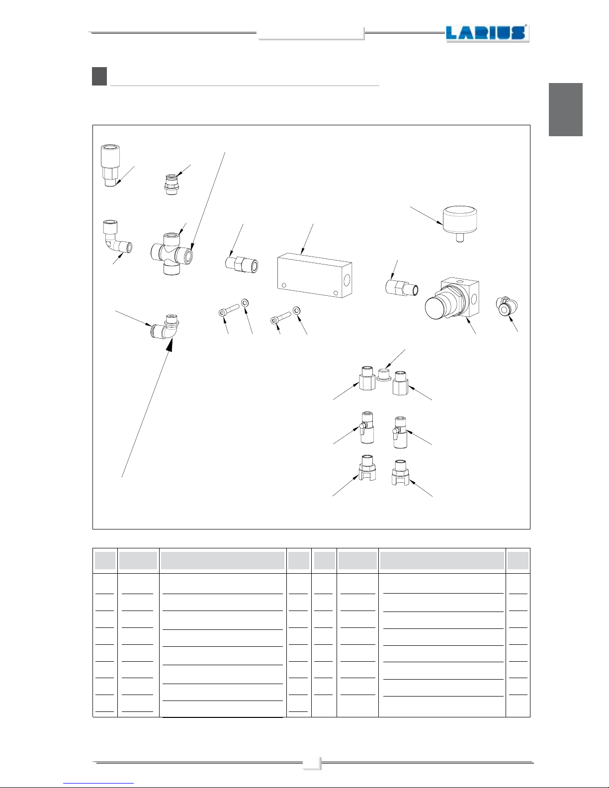
53
NOVA MIX 2K
English
Z
AIR DISTRIBUTOR ASSEMBLY REF. 24477
Pos.
Slide quick coupling
90° M-F 1/4 Connector
1/4"
quick attachment for diam.8 tube
1/4 cross connection
90°1/4"quick attachment for diam.8 tube
3/8-1/4" Nipple
conical-conical
Air distributor
Regulator
1.
2
3
4
5
6
7
8
1
1
1
4
2
2
1
1
Pos.
9
10
11
12
13
14
15
0-8 bar manometer
Tap 1/4
3/8-1/4 M-F Reduction
1/4 Ball valve
Bayonet attachment
Washer d.5
Screw TCE UNI5931 M5x35
1
1
2
2
2
2
2
95319
5255
4006
23533
8063
3560
24480
3344
8167
8083
22027
4004
10103
33023
510067
Code Description Q.ty Code Description Q.ty
WARNING: Always indicate code and quantity for each part required.
1
2
3
4
5
5
6
6
7
8
9
15 14 15 14
fornito solo con
L'AIR ELECTRIC GENERATOR
10
1111
12 12
13 13
fornito solo con
L'AIR ELECTRIC GENERATOR
Only provided witd
AIR ELECTRIC GENERATOR
Only provided witd
AIR ELECTRIC GENERATOR

54
NOVA MIX 2K
English
AA
GROUP ASSEMBLY RL FOR NOVA PUMP REF. 24478 RIGHT
FOR COMPONENT
"A"
Pos.
1" Nipple
conical-cylindrical gasket
1"-3/4" Reduction
Slide valve
1"-3/4" M-F Reduction
1" M-F Elbow
1
2
3
4
5,
3
1
1
1
2
Pos.
6
7
7,
8
9
Manometer
RL 1" Group right
RL 1" Group left
Screw TCE M5X70 UNI 5931
NIPPLO 1" CON-CIL
1
1
1
2
1
8375
510109
95323
95313
95031
96259
24482
24482/1
37221
8375
Code Description Q.ty Code Description Q.ty
WARNING: Always indicate code and quantity for each part required.
IN
OUT
1
2
3
9
5
7
6
5
4
1
8
8
NOTE: GROUP ASSEMBLY RL FOR NOVA PUMP REF. 24478/SX LEFT
FOR COMPONENT "B".

55
NOVA MIX 2K
English
1
2
3
3
4
5
7
8
6
AB
AIR SUPPLY TANK REF. 24479
Pos.
Air supply tank
Collar 3"
1/2"-1/4" MF Reduction
1/4" MF Adapter elbow
1.
2
3
4
1
1
2
1
Pos.
5
6
7
8
1/4" mm Adapter
conical
1/4"
quick attachment for diam.8 tube
Check valve
1
1
1
23546
4413
5356
5255
23383
4006
23403
Code Description Q.ty Code Description Q.ty
WARNING: Always indicate code and quantity for each part required.

56
NOVA MIX 2K
English
AC
AIR REGULATOR FOR WASH PUMP REF. 24484
Pos.
1/2" M.F.Connector elbow
1/2" Adapter
conical-cylindrical gasket
Rotating connector 3/8"-1/2" MF
Air regulator 3/8"
1.
2
3
4
1
1
1
1
Pos.
5
6
7
8
3/8"
quick attachment for diam.12 tube
Adapter 1/8 M.F.
1/8" M.F. Adapter elbow
Manometer BP
1
2
1
1
20451
96255
8069
91736
96215
3343
3341
96259
Code Description Q.ty Code Description Q.ty
WARNING: Always indicate code and quantity for each part required.
1
2
3 4
5
6
6
7
8
Rif. 24484/1
Pos. Codice
3
4
5
6
7
8
24484 / 1

57
NOVA MIX 2K
English
1
2
3
3
3
3
4
4
4
4
AD
GHIBLI REDUCER ASSEMBLY REF. 24487
Pos.
Ghibli 40:1 Div. Inox pump
Reduction plate
1.
2
1
1
Pos.
3
4
Washer UNI 6592 d.10
Screw UNI 5931 TCE M10x25
4
4
96057
24467
81033
6656
Code Description Q.ty Code Description Q.ty
WARNING: Always indicate code and quantity for each part required.

58
NOVA MIX 2K
English
1 2 3 4
4
3
5 6
7
AE
ENCODER KIT FOR COMPONENT DOSAGE REF. 24488
Pos.
Encoder wire
Bracket 1 for encoder
Washer d.4 UNI 6592 Zn
Screw TCE UNI 5931 M4x10
1.
2
3
4
1
1
3
3
Pos.
5
6
7
Washer d.6 UNI 6592 Zn
Screw TCE UNI 5931 M6x20
Bracket 2 for mounting on pump Nova
2
2
1
24490
24491
5339
5378
95068
91062
24492
Code Description Q.ty Code Description Q.ty
WARNING: Always indicate code and quantity for each part required.

59
NOVA MIX 2K
English
1
2
2
3
3
4
AF
FLOWMETER KIT FOR GHIBLI MIX COMP. DOSAGE REF. 24489
Pos.
3/8" Adapter
conical-cylindrical gasket
MF 3/8" Revolving adapter
1.
2
1
2
Pos.
3
4
3/8" Seal
Flowmeter unit
2
1
6149
23161
33010
23401
Code Description Q.ty Code Description Q.ty
WARNING: Always indicate code and quantity for each part required.

60
NOVA MIX 2K
English
1
2
2
3
3
3
3
4
6
6
5
7
8
10
11
12
9
13
AG
HEATER WITH A COMPONENT REF. 24493
Pos.
Heater
Elbow c
onnector
3/8" MF
Adapter 3/8"
conical
Termometer + connector 3/8"
T-connector 3/8"
3/8" Ball valve
3/8" Seal
Code
Ref. 24493
1
2
3
4
5,
6
7,
1
2
4
1+1
1
2
1
Q.ty
8
9
10
11
12
13
Adapter 3/8" cil-M20x2
M16x1.5 MF Revolving conn. elbow
Adapter 3/8"
conical-cyl. gasket
Elbow
connector 3/8" MF bp
Adapter M16x1.5
Elbow c
onnector 1/2" MF bp
1
1
1
1
1
1
6099
8078
6149/1
6139+6164
8078/1
33034
33010
3387
4709
95230
3121
6148
20811
Code
Ref. 24493/1
vers. INOX
6099
8074
6149/1
6139+6164
3379
33037
33010
Code
Ref. 24493
Description
Code
Ref. 24493/1
vers. INOX
Pos.
3385
4709
6149
3121
95284
20811
WARNING: Always indicate code and quantity for each part required.
Description Q.ty

61
NOVA MIX 2K
English
1
11
9
12
3
3
4
2
8
7
6
3
5
3
6
10
AH
HEATER WITH B COMPONENT REF. 23494
Pos.
Heater
Elbow c
onnector
3/8" MF
Adapter 3/8"
conical
Termometer + connector 3/8"
T-connector 3/8"
Ball valve 3/8" ap
Code
Ref. 24494
1
2
3
4
5,
6
1
2
4
1+1
1
2
7,
8
9
10
11
12
3/8" seal
Adapter 3/8" cil-M20x2
M16x1.5 MF Revolving conn. elbow
Adapter 3/8"
conical-cyl. gasket
Adapter M16x1.5
Elbow c
onnector 1/2" MF bp
1
1
1
1
1
1
6099
8078
6149/1
6139+6164
8078/1
33034
33010
3387
4709
95230
95284
20811
Code
Ref. 24494/1
vers. INOX
6099
8074
6149/1
6139+6164
3379
33037
Code
Ref. 24494
Code
Ref. 24494/1
vers. INOX
Pos.
33010
3385
4709
6149
6148
20811
WARNING: Always indicate code and quantity for each part required.
Q.ty
Description
Q.ty
Description

62
NOVA MIX 2K
English
RIF. 24496/1
RIF. 24496
123 4
5
6
7
7
8
AI
WHEEL REF. 24496
Pos.
Self-tightening nut M12
Washer d.12
Screw TCE UNI 5931 M12x35
Washer d.8
1.
2
3
4
2
2
2
2
Pos.
5
6
7
8
Full front wheel
Screw TCE UNI 5931 M12x35
Washer d.12
Self-tightening nut M12
1
4
8
4
4493/1
24495
34008
95153
24497
7112
95066
5756
Code Description Q.ty Code Description Q.ty
WARNING: Always indicate code and quantity for each part required.
WHEEL LEFT AND RIGHT

63
NOVA MIX 2K
English
1
14
2
14
3
3
4
4
4
5
6
7
7
8
9
10
11
12
12
13
13
Pos.
1
2
3
4
5,
6
7,
1
1
2
3
1
1
2
Pos.
8
9
10
11
12
13
14
1
1
1
1
2
2
2
23320
23321
23340/4
37406
23161
8071
23323
3637
23324
23325/1
23329
23327
96753
23328
23340
AJ
Code Description
Q.ty Code Description
Q.ty
WARNING: Always indicate code and quantity for each part required.
Complete mixer + spray guns kit
Mixer body
Wash gun unit
Screw
Rotating connector
Gasket d. 1/2"
Support plate
Self-tightening nut
Intake connector
Mixing tube
Outlet connector
Spiral mixer
Washer
Locking nut
Material gun unit
MIXER + SPRAY GUNS (REF. 23320) EXPLODED VIEW

64
NOVA MIX 2K
English
Pos.
18
19
1
1
33012
3110
Pos.
18
19
20
21
1
2
1
1
33012
37107
23412
95230
AK
Code Description Q.ty
WARNING: Always indicate code and quantity for each part required.
Code Description Q.ty
SPRAY GUN EXPLODED VIEW LA 95 REF. 23340/4
1/4 Gasket
1/4-1/4 CIL-CON Adapter
1/4 Gasket
1/4-3/8 CIL-CON Adapter
Check valve
3/8-3/8 CON-CIL Adapter
Components for wash gun on Larius Mix 2K Ref. 23340/2
Components for wash gun on Larius Mix 2K Ref.23340/1
1
2
3
4
5
6
7
8
9
15
16
16
11
10
17
18
14
13
13
14
12
19
20
21
5A
5B
6A
6B
6C

65
NOVA MIX 2K
English
Pos.
18
19
20
21
1
1
1
1
33012
3110
23403
3110
Code Description Q.ty
1/4 Gasket
1/4-3/8 CIL-CON Adapter
Check valve
3/8-3/8 CON-CIL Adapter
Components for wash gun on Larius Mix 2K Ref.23340/3
Pos.
Kit pistola completo
Housing
Piston
Rear spray gun stopper
Gasket
Sleeve complete
Sleeve
Ball seat
Rod complete
Ball 0 5
Prick punck
Rod
Seal holder ring
Gasket
Seal holder screw
OR 2043
OR 3131
Nut
Ball 0 4
Self-tightening nut
Spring
1/4” rotating elbow
OR 3162
Codice Descrizione
1
2
3
4
5
5A
5B
6
6A
6B
6C
7,
8
9
10
11
12
13
14
15
16
17
Q.tà
1
1
1
1
1
1
1
1
1
1
1
1
1
1
1
1
1
2
2
1
2
1
23340/4
23341
23342
23343
33007
23336
11216/1
11004/2
23330
11005/3
23331
23332
23333
23334
23335
23338
23339
5114
5339
4043
11814
8063
23348

66
NOVA MIX 2K
English
A-B
ACCESSORIES
Art. 11250: AT 250 1/4"
Art. 11200: AT 250 M16X1,5
Art. 11131: L91X 1/4"
Art. 11130: L91X M16X1,5
AUTOMATIC SPRAY-GUN LA95
Art. 11700
LOW PRESSURE SPRAY-GUN MA98L
Art. 11300
MANUAL MIST-LESS SPRAY-GUN 07
Art. 19950
MANUAL MIST-LESS SPRAY-GUN
Version with MIST-CLEAN nozzle Art. 19960
AUTOMATIC MIST-LESS SPRAY-GUN High finish
Art. 11820
MANUALE LOW PRESSION SPRAY-GUN V71

67
NOVA MIX 2K
English
PISTON GUNSTOCK FILTERS
Art.
11039: Green (30M) -
Art.
11038: White (60M)
Art.
11037: Yellow (100M) -
Art.
11019: Red (200M)
FILTER
Art. 95218: MESH 30M
Art. 95219: MESH 60M
Art. 95220: MESH 100M
Art. 95221: MESH 200M
Art.
7030: AP FLOW REGULATOR
STAR 2001 SERIES SPRAY-GUN (MANUAL AND AUTOMATIC)
PAIR OF FILTERS FOR COMPONENT INTAKE
Art. 23250/1
OUTPUT FOR TWO GUNS
Art. 11000: AT 300 M16x1,5
Art. 11090: AT 300 1/4"

68
NOVA MIX 2K
English
KIT FOR COMPONENT DOSAGE CONTROL
Art. 23140:
LOW PRESSURE STAINLESS STEEL PRESSURE GAUGE
Art. 150/1:
EXTENSION
Art. 153: cm 30 -Art. 153: cm 40
Art. 155: cm 60 - Art. 158: cm 80 - Art. 156: cm 100
Art.
6099: HEATER
HIGH PRESSURE STAINLESS STEEL PRESSURE GAUGE
Code 150: 1/4"

69
NOVA MIX 2K
English
Code 18280: GASKET
Code 18270: SUPER FAST-CLEAN base UE 11/16x16
SUPER FAST-CLEAN TIP
SUPER FAST-CLEAN
Nozzles code
SFC07-20
SFC07-40
SFC09-20
SFC09-40
SFC11-20
SFC11-40
SFC13-20
SFC13-40
SFC13-60
SFC15-20
SFC15-40
SFC15-60
SFC17-20
SFC17-40
SFC17-60
SFC19-20
SFC19-40
SFC19-60
SFC21-20
SFC21-40
SFC21-60
SFC23-20
SFC23-40
SFC23-60
SFC25-20
SFC25-40
SFC25-60
SFC27-20
SFC27-40
SFC27-60
SFC27-80
SFC29-20
SFC29-40
SFC29-60
SFC29-80
SFC31-40
SFC31-60
SFC31-80
SFC33-40
SFC33-60
SFC33-80
SFC39-40
SFC39-60
SFC39-80
SFC43-40
SFC43-60
SFC43-80
SFC51-40
SFC51-60
SFC51-80

23801 CALOLZIOCORTE - LECCO - ITALY - Via Antonio Stoppani, 21
Tel. (39) 0341/ 62. 11.52 - Fax (39) 0341/62.12.4 3
E-mail: larius@larius.com - Internet http://www.larius.com
MANUFACTURER
:
DIRECT LINE
Tel. (39) 0341/621256
Fax (39) 0341/621234
CUSTOMERS TECHNICAL SERVICE
ELECTRONIC DOSING BI-COMPONENT SYSTEMS
GHIBLI MIX 2K 40:1 INOX con air
electric generator - Cod. 24566
VEGA MIX 2K 5:1 INOX
Cod. 24571
LARIUS MINI MIX su carrello
Cod. 24001
MIX 2K - Cod. 23000
 Loading...