

www.larius.eu
CH 200 AD
OPERATING AND MAINTENANCE INSTRUCTION
ITALIANO
Ediz. 03 - 06/2019

WE ADVISE THE USE OF THIS EQUIPMENT ONLY BY PROFESSIONAL OPERATORS.
ONLY USE THIS MACHINE FOR USAGE SPECIFICALLY MENTIONED IN THIS MANUAL.
Thank you for choosing a LARIUS S.R.L. product.
As well as the product purchased, you will receive a range of support services
enabling you to achieve the results desired, quickly and professionally.
Due to a constant product improvement programme, the factory reserves the right to modify technical
details mentioned in this manual without prior notice.
This manual is to be considered as an English language translation of the original manual in Italian.
The manufacturer shall bear no responsibility for any damages or inconveniences that may arise due
to the incorrect translation of the instructions contained within the original manual in Italian.
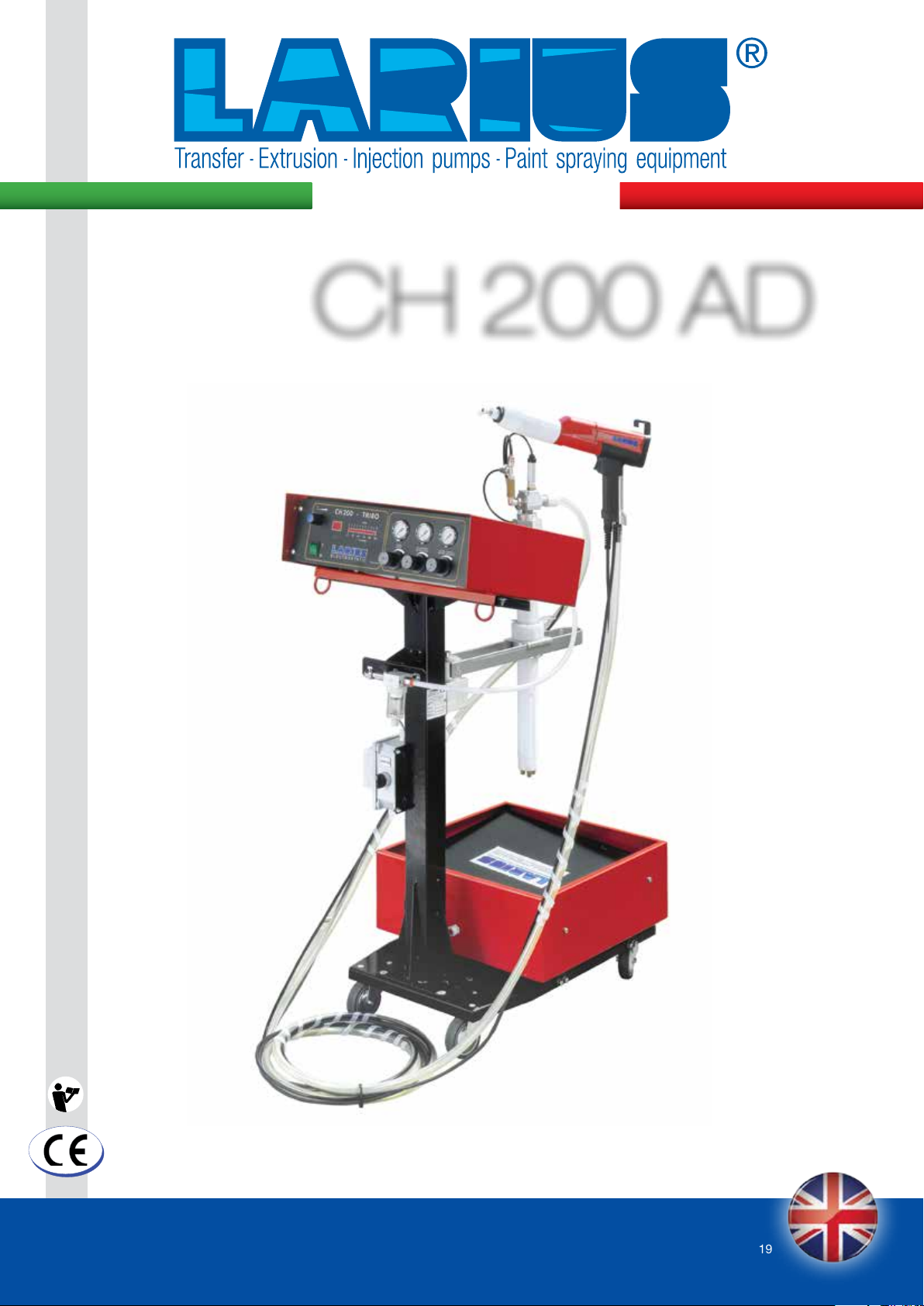
POWDER COATING SYSTEM
POWDER COATING SYSTEM
CH 200 AD
INTRODUCTION .................................................. p.1
WARNINGS .......................................................... p.2
A
PRINCIPLE OF OPERATION ............................... p.3
TECHNICAL DATA ............................................... p.4
B
DESCRIPTION OF THE EQUIPMENT ................. p.5
C
D
TRANSPORT AND UNPACKING ......................... p.6
E
SAFETY REGULATIONS ...................................... p.6
Electrical safety regulations ........................... p.7
Precautions during work ................................. p.7
CONDITIONS OF GUARANTEE .......................... p.6
F
CORRECT USE OF THE SYSTEM ....................... p.8
G
INCORRECT USE OF THE SYSTEM
H
CONTROL PANEL ................................................ p.9
Operating controls
Current output adjustment µa
Connections .................................................... p.11
Operation ......................................................... p.13
Use with CH spray gun (corona effect) .......... p.13
Use with triboelectric spraying gun ............... p.15
I
CYCLICAL ROUTINE MAINTENANCE ................ p.16
J
COLOR CHANGE ................................................. p.18
J
K
PROBLEMS AND SOLUTIONS ........................... p.19
............................................... p.9
.....................p.9
........................... p.11
SPARE PARTS
SHAKING TABLE CH-200-AD ............................. p.24
L
M
FRAME SPARE PARTS CH-200-AD .................... p.24
N
ELECTROPNEUMATIC GENERATOR ................. p.28
O
CH 200 MANUAL GUN REF.9700 ........................ p.30
P
SPARE PARTS FOR AUTOMATIC GUN
CH 200 REF.9705 ................................................. p.32
Q
SPARE PARTS FOR AUTOMATIC AND MANUAL
TRIBO SPRAY GUN ............................................. p.34
CONE JET NOZZLE SPRAY GUN FOR CH 200
R
SPARE PARTS FOR CONE JET NOZZLE WITH
S
EXTENSION FOR CH 200
FAN NOZZLE SPARE PARTS FOR CH 200
T
HIGH PERFORMACE NOZZLE SPARE PARTS
U
FOR CH 200
V
MULTI-DIFFUSION NOZZLE SPARE PARTS
FOR CH 200
Z
POWDER DELIVERY PUMP SPARE PARTS
REF.5505
Y
ACCESSORIES .................................................... p.42
.......................................................... p.39
.......................................................... p.40
............................................................... p.41
...................................... p.37
..... p.36
............ p.38
Edit. 03 - 06/2019
www.larius.eu
1
CH 200 AD
WARNINGS
Carefully read this manual before using the machine.
Improper use may cause damage to persons or property.
Do not use the spray gun if you are under the influence of drugs or alcohol.
Do not modify the spray gun for any reason.
Use products and solvents that are compatible with the different parts of the spray gun, carefully reading the manufacturer's warnings.
Refer to the Technical Data of the spray gun in this manual.
Check the spray gun daily; if worn parts are noted, replace them using ONLY original spare parts.
Keep children and animals away from the work area.
Observe all safety regulations.
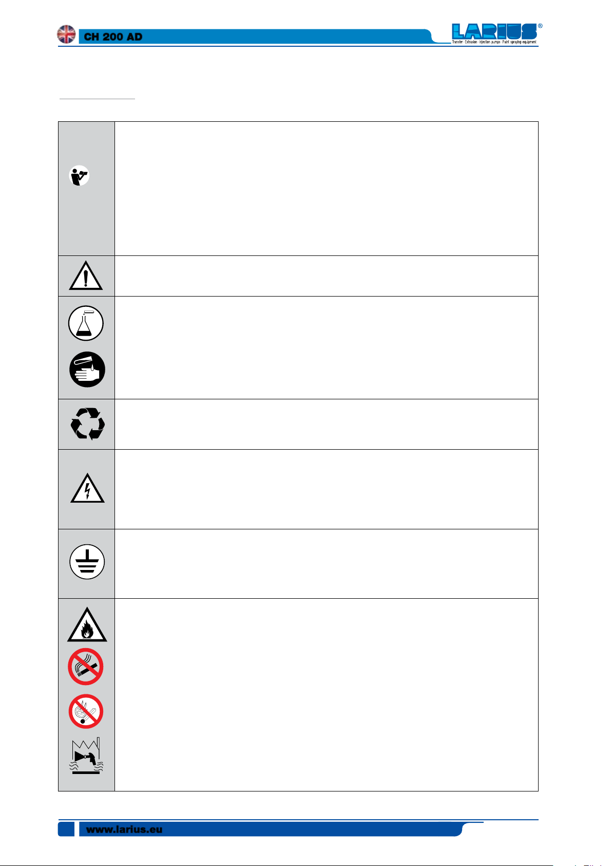
This symbol signals the risk of injury or serious damage to the machine if the warning is not heeded.
These symbols signal the risk of chemical reactions and the risk of explosion if the warning is not heeded.
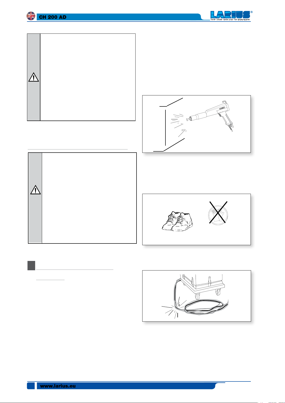
There is a danger of serious injury caused by contact with the spray gun jet, if injury occurs IMMEDIATELY seek
medical care, specifying the type of product injected.
Do not spray without having installed the nozzle guard and the spray gun trigger guard.
Do not place fingers on the spray gun nozzle.
At the end of the work cycle and before performing any maintenance operation, follow the pressure relief procedure
included in this manual.
The meanings of the symbols used in the manual that concern use as well as use, maintenance and
repair operations of this machine are described in the following table.
This symbol signals important instructions and recommendations for the environmentally-friendly disposal or re
cycling of a product.
This symbol signals the risk of electric shock if the warning is not heeded and the presence of electric voltage.
Store in a place with no humidity and do not expose to rain.
Check to make sure the cables are intact.
Switch off the machine and discharge any residual voltage supply before performing cleaning and maintenance
operations.
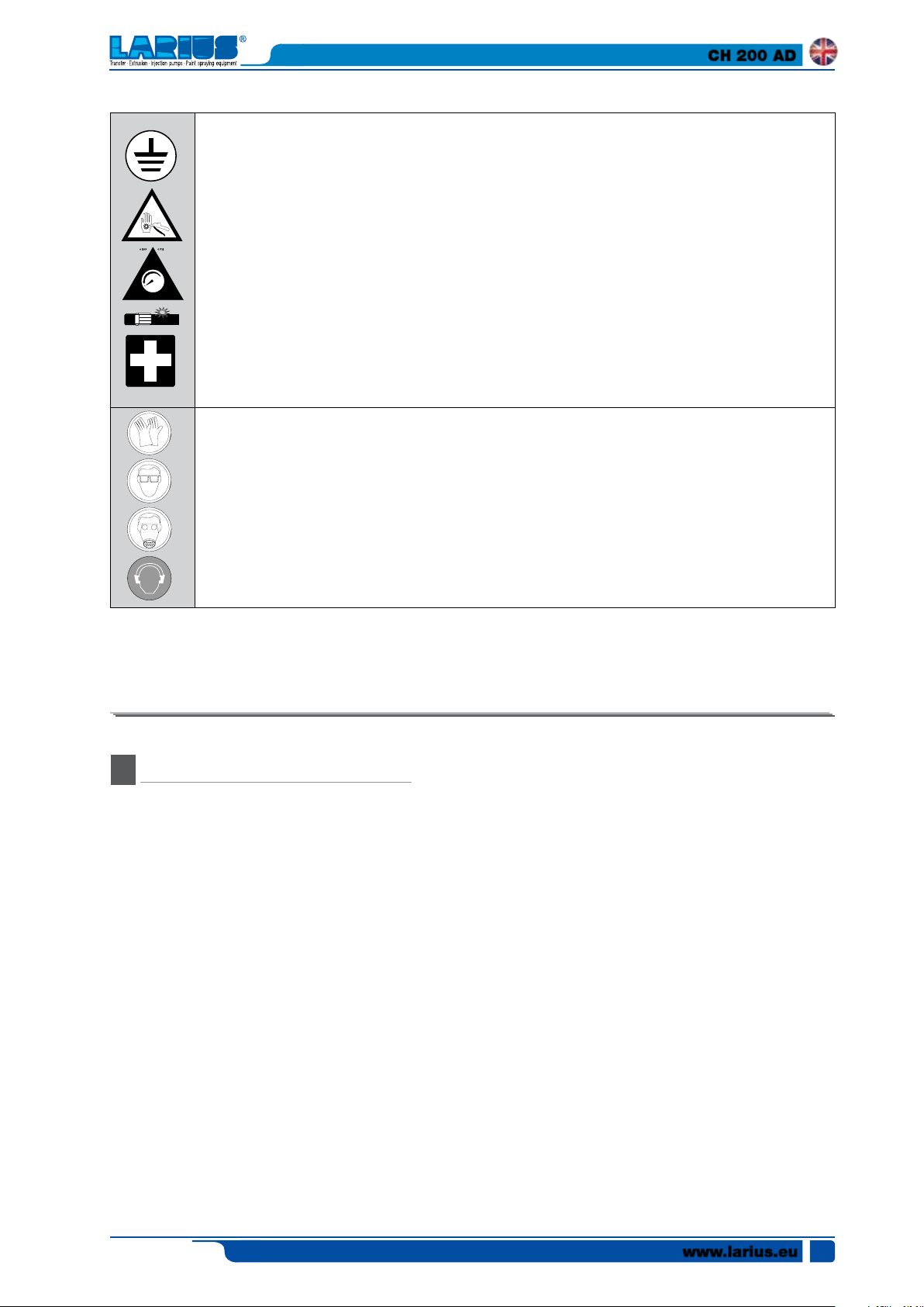
This symbol signals the presence of a terminal with a grounding cable.
Use ONLY three-wire extensions and electrical outlets with grounding connections.
Before beginning work, make sure the electrical system is equipped with a grounding connection and that it complies
with the safety regulations.
FIRE AND EXPLOSION HAZARD
Flammable fumes, like solvent and paint fumes can ignite and may explode.
To prevent fire or explosion:
- Use the machine ONLY in well-ventilated areas.
Eliminate all possible sources of ignition; such as pilot lights, cigarettes, flashlights, synthetic clothing (potential static
arc), etc.
- Ground the machine and all conductive objects in the work area.
- Only use airless conductive tubes that are grounded.
- Do not use trichloroethane, methylene chloride, other halogenated hydrocarbon solvents or fluids containing such
solvents in aluminium devices that are under pressure. This may cause a dangerous chemical reaction that may
could result in an explosion.
If electric charges or shocks are detected immediately interrupt the operation you are performing with the machine.
Keep a fire extinguisher in the immediate vicinity of the work area.
-
www.larius.eu
2
Edit. 03 - 06/2019
CH 200 AD
DANGER OF HIGH PRESSURE FLUID INJECTION
The high pressure fluid that comes out of the spray gun or from any leaks may penetrate the skin and cause lacerations.
To prevent fire or fluid injection:
- Enable the spray gun's trigger safety lock when not spraying.
- Do not place hands or fingers on the nozzle of the spray gun. Do not try and stop leaks with your hands, body or
other.
- Do not point the spray gun towards yourself or anyone else.
- Do not spray without the special nozzle guard.
-
Discharge the pressure of the system after spraying and before performing any maintenance operations.
- Do not use components whose operating pressure is less than the maximum pressure of the system.
- Do not allow children to use this machine.
- Be careful of the possible backlash when you pull the spray gun trigger.
If the high pressure fluid penetrates the skin, the wound may seem like a "simple
cut" but, in reality, it could
affected area.
These symbols signal the obligation to wear protective gloves, goggles and masks.
Wear clothing that complies with safety regulations in force in the country of the user.
Do not wear bracelets, earrings, rings, chains or other objects that may obstruct the operator's work.
Do not wear clothing with large sleeves, scarves, ties or any other item that can become tangled in the moving parts
of the machine during the operating cycle and inspection and maintenance operations.
be a very serious injury. Immediately provide medical treatment to the
PRINCIPLE OF OPERATION
A
This type of machine constitutes a complete and independent
unit for the application of powder coatings.
LARIUS has created this AD CH 200-TRIBO unit which allows
the use of corona effect spray guns (the powder is charged by
electrodes), and triboelectric spray guns (the charge occurs
via friction).
Therefore the same machine can be used as an electrostatic
generator for CH 200 series spray guns, or as a control unit
for the electrostatic charge for LARIUS TRIBO manual and
automatic spray guns.
The conversion from one system to the other occurs via the
simple touch of a switch.
The AD version is the ideal solution when frequent colour
changes are required. As a matter of fact, the powder is sucked
up directly by the original package. If necessary just replace
the box with the powder and clean the suction tube.
Edit. 03 - 06/2019
www.larius.eu
3
CH 200 AD
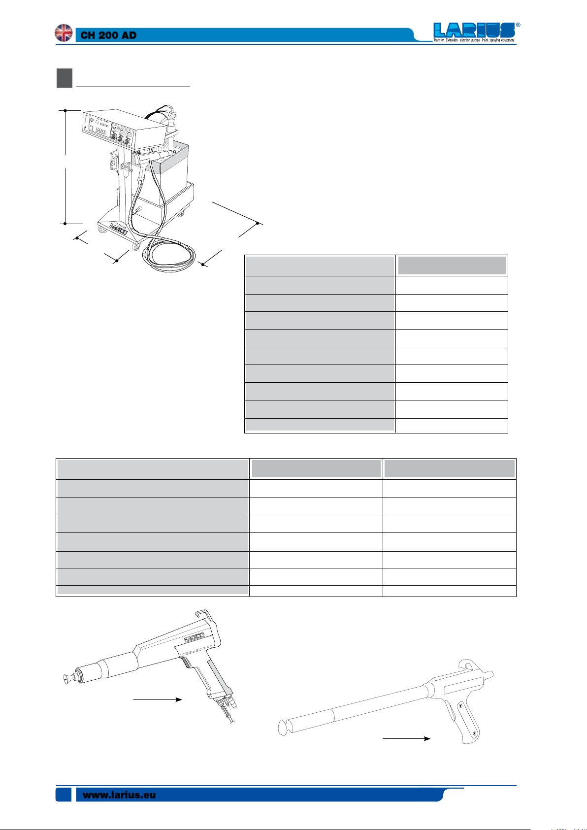
TECHNICAL DATA
B
C
B
SUPPLY VOLTAGE
OUTPUT VOLTAGE
NOMINAL CURRENT
POLARITY
WEIGHT
LENGTH
A
SUPPLY VOLTAGE
INSTALLED POWER
FREQUENCY
POWDER FLOW
WEIGHT
LENGTH
WIDTH
HEIGHT
approx. 12 V
0-120 KV c.c.
µA
0-190
Negative
690 g
360 mm
CH 200 - TRIBO /AD
120-220 Vca
60 W
50 Hz
3-20 kg/h
55 Kg
(A) 490 mm
(B) 800 mm
(C) 1100 mm
SPRAY GUN TRIBOSPRAY GUN CH 200
-
-
-
Positive
590 g
450 mm
www.larius.eu
4
CH 200 Spray gun
TRIBO Spray gun
Edit. 03 - 06/2019
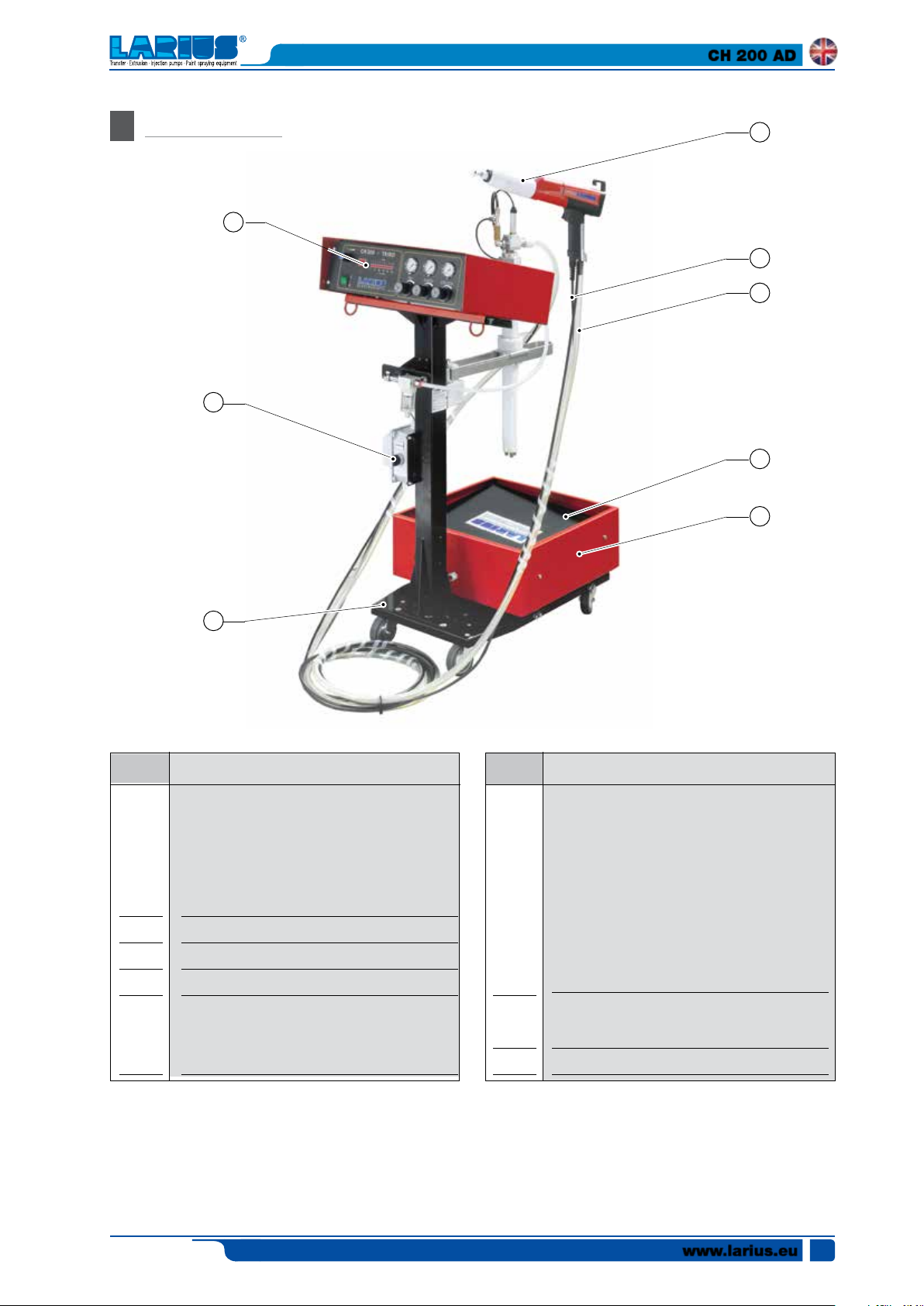
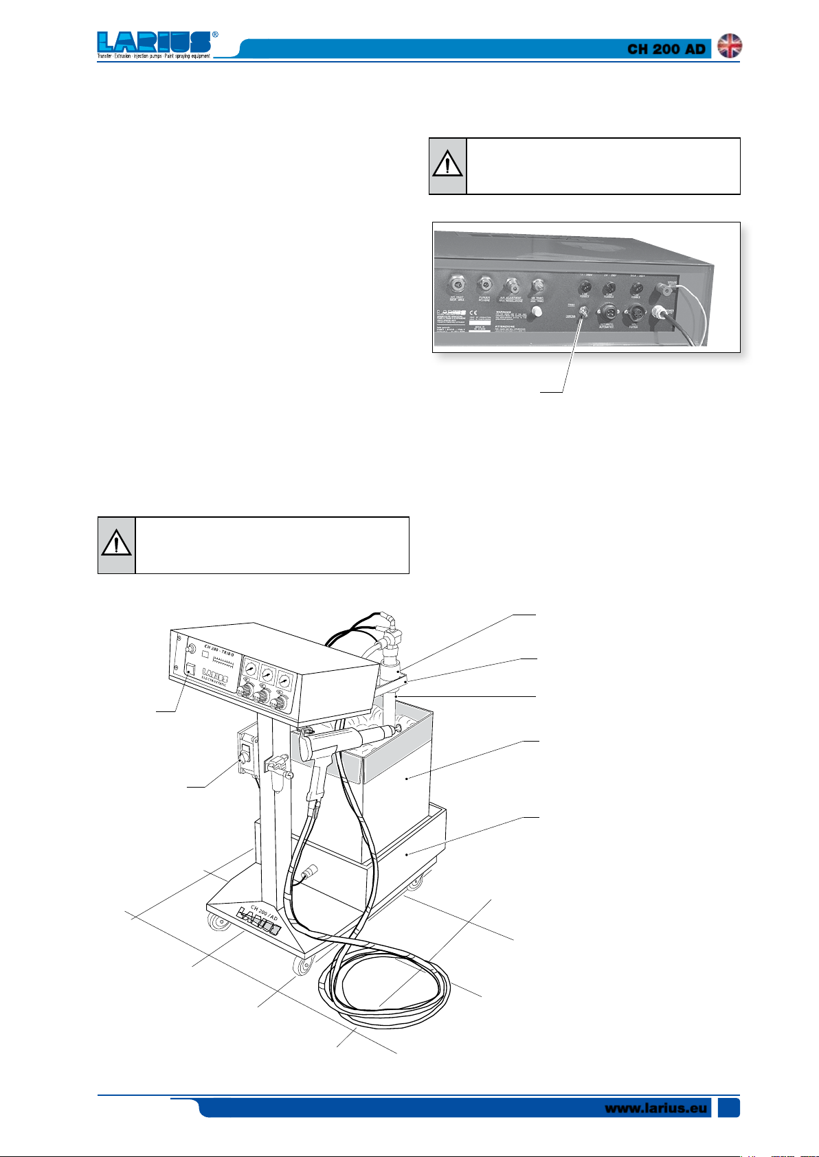
MAIN PARTS
C
8
CH 200 AD
6
1
3
2
7
REP.
1
.
2
3.
4
5
.
4
Description Description
RACK electrostatic generator which en-
closes all the power and control circuits,
both electrical and pneumatic, as well as
the safety systems, and digital display
of operating voltage and current.
Powder supply tube.
Power supply cable for manual spray gun.
Support trolley with rotating wheels.
Interchangeable powder container for
using different colour powders (max.
recommended capacity 25 kg).
REP.
6
.
7
.
8
5
CH200 powder spray gun, composed
of a black of epoxy resin cast under
pressure and treated withresins for total
safety during operation. The voltage
multiplier protected by insulating resins
is housed inside the body of the spray
gun (which can be used with CH 200 -
TRIBO triboelectric spray guns).
Vibrating shaking table with inclined
surface, complete with electric vibrator.
Switch for electric vibrator
Edit. 03 - 06/2019
www.larius.eu
5
CH 200 AD
TRANSPORT AND
D
UNPACKING
• Carefully observe the position of the packaging indicated
on the outside by writing or symbols.
• Before installing the machine, prepare an area that is
suitable in size, has the correct lighting, and a clean
and smooth floor.
All operations of unloading and handling of the
machine are the responsibility of the user, who
must be very careful to avoid causing damage or
injury to persons or the machine.
Only specialised and qualified personnel (forklift
drivers, crane operators, etc.) and suitable lifting
equipment with a capacity that can support the
weight of the packaging and that complies with
safety regulations should be employed for unloading operations.
Personnel must be equipped with the necessary
personal protection equipment.
•
The manufacturer declines all responsibility regarding the
unloading and transport of the machine in the workplace.
• Upon receipt of the machine, verify the packaging is
intact. Remove the machine from its packaging and
check that it has not been damaged during transport.
If damaged components are noted, contact LARIUS
and the shipping agent in a timely manner. Any damage
noted must be communicated within a maximum of 8
days from receipt of the system.
The communication must be made via registered mail
with return receipt, addressed to LARIUS and the
shipping agent.
The disposal of packaging materials, which is the
responsibility of the user, must be carried out in
compliance with laws in force in the country where
the machine is used.
However, it is good practice to recycle the
packaging materials as much as possible in an
environmentally-friendly way.
SAFETY REGULATIONS
E
• THE EMPLOYER MUST EDUCATE PERSONNEL ABOUT
THE RISKS OF INJURIES, OPERATOR SAFETY DEVICES
AND THE GENERAL ACCIDENT PREVENTION RULES
ESTABLISHED BY INTERNATIONAL DIRECTIVES AND
LEGISLATION IN THE COUNTRY WHERE THE MACHINE IS
INSTALLED IN ADDITION TO REGULATIONS CONCERNING
ENVIRONMENTAL POLLUTION.
•
• KEEP THE WORK AREA IN ORDER. DISORDER IN THE
• ALWAYS KEEP YOUR BALANCE, AVOIDING UNSAFE
• BEFORE USE THOROUGHLY CHECK THAT THERE ARE
• ALWAYS OBSERVE SAFETY INSTRUCTIONS AND REGU-
• DO NOT ALLOW PERSONS NOT INVOLED IN THE OP-
• NEVER EXCEED THE MAXIMUM OPERATING PRESSURES
• NEVER POINT THE SPRAY GUN TOWARDS YOURSELF OR
• ALWAYS DISCONNECT THE POWER SUPPLY AND
• NEVER MODIFY ANY COMPONENT OF THE MACHINE.
PERSONNEL MUST CAREFULLY OBSERVE ACCIDENT
PREVENTION REGULATIONS OF THE COUNTRY WHERE
THE MACHINE IS INSTALLED AS WELL AS REGULATIONS
CONCERNING ENVIRONMENTAL POLLUTION.
Carefully read the following instructions in their
entirety before using the machine.
Keep these instructions in a safe place.
The non-authorised tampering with or replacement
of one or more parts that make up the machine, the
use of accessories, tools and consumable materials
that are different from those recommended by the
manufacturer may cause accidents and relieves
the manufacturer from all civil and penal liabilities.
WORKPLACE CAUSES DANGER AND ACCIDENTS.
POSITIONS.
NO DAMAGED PARTS AND THAT THE MACHINE IS ABLE
TO PROPERLY CARRY OUT ITS FUNCTION.
LATIONS IN FORCE.
ERATION OF THE MACHINE TO ACCESS THE WORK
AREA.
INDICATED.
OTHERS. DIRECT CONTACT WITH THE JET MAY CAUSE
SERIOUS INJURY. IN CASE INJURIES ARE CAUSED BY
THE SPRAY GUN JET IMMEDIATELY SEEK MEDICAL
ATTENTION, SPECIFYING THE TYPE OF PRODUCT ABSORBED BY THE SKIN. NEVER UNDERESTIMATE AN
INJURY CAUSED BY FLUID INJECTION.
DISCHARGE THE PRESSURE IN THE CIRCUIT BEFORE
PERFORMING ANY TYPE OF INSPECTION OR REPLACEMENT OF COMPONENTS OF THE MACHINE.
REGULARLY INSPECT THE COMPONENTS OF THE MACHINE. REPLACE DAMAGED OR WORN PARTS.
www.larius.eu
6
Edit. 03 - 06/2019
CH 200 AD
• TIGHTEN AND CHECK ALL THE CONNECTION FITTINGS
BETWEEN THE PUMP, THE FLEXIBLE TUBE AND THE
SPRAY GUN BEFORE USING THIS MACHINE.
• ALWAYS USE THE FLEXIBLE TUBE PROVIDED IN THE
STANDARD WORK KIT. THE USE OF ACCESSORIES OR
EQUIPMENT DIFFERENT THAN THOSE RECOMMENDED
IN THIS MANUAL MAY CAUSE INJURY.
• THE FLUID CONTAINED IN THE FLEXIBLE TUBE MAY BE
VERY DANGEROUS. HANDLE THE FLEXIBLE TUBE WITH
CARE. DO NOT PULL THE FLEXIBLE TUBE TO MOVE THE
MACHINE. NEVER USED A DAMAGED OR REPAIRED
FLEXIBLE TUBE.
If the product flows at high speed through the
flexible tube static electricity may be created,
manifested with small shocks and sparks. The
• To prevent injuries, repairs of electrical parts must only be
machine should be electrically grounded. The
pump is grounded by the grounding wire of the
power cable. The spray gun is grounded via a high
pressure flexible tube. All the conductive objects
that are near the work area must be grounded.
• ABSOLUTELY AVOID SPRAYING FLAMMABLE PRODUCTS
OR SOLVENTS IN CLOSED ENVIRONMENTS.
• ABSOLUTELY AVOID USING THE MACHINE IN ENVIRONMENTS SATURATED WITH POTENTIALLY EXPLOSIVE
GASES
Always verify the compatibility of the product with
the materials that make up the system (pump, spray
gun, flexible tube and accessories) with which it may
come into contact. Do not use paints or solvents
that contain halogenated hydrocarbons (such
as methylene chloride). Products in contact with
aluminium parts of the machine may cause dangerous chemical reactions with risk of explosion.
Electrical safety regulations
Ensure the switch is in the “OFF” position before inserting
•
the power cable plug into the electrical outlet.
• Do not transport the machine if it is connected to the power
supply network.
• Disconnect the plug from the outlet if the machine is not in
use and before performing all maintenance or accessory
replacement operations.
• Do not drag the machine or disconnect the plug by pulling
on the power cable.
• Keep the cable away from heat, mineral oils and sharp
edges.
• If the machine is used outdoors, use a suitable extension
cord, that is intended and marked for outdoor use.
Never tamper with the calibration values of the
instruments.
carried out by qualified personnel.
PRECAUTIONS DURING WORK
• Do not smoke, do not cause open flames.
• Only the spray guns and the vehicles required for trans-
porting the powders must be in the booths: all other the
electrical devices must be outside the booth.
• Ensure that suction capacity in the spray booth is sufficient
and that the powder does not accumulate in any part of
the booth.
• Verify that the frames and all the electrical devices are
properly grounded.
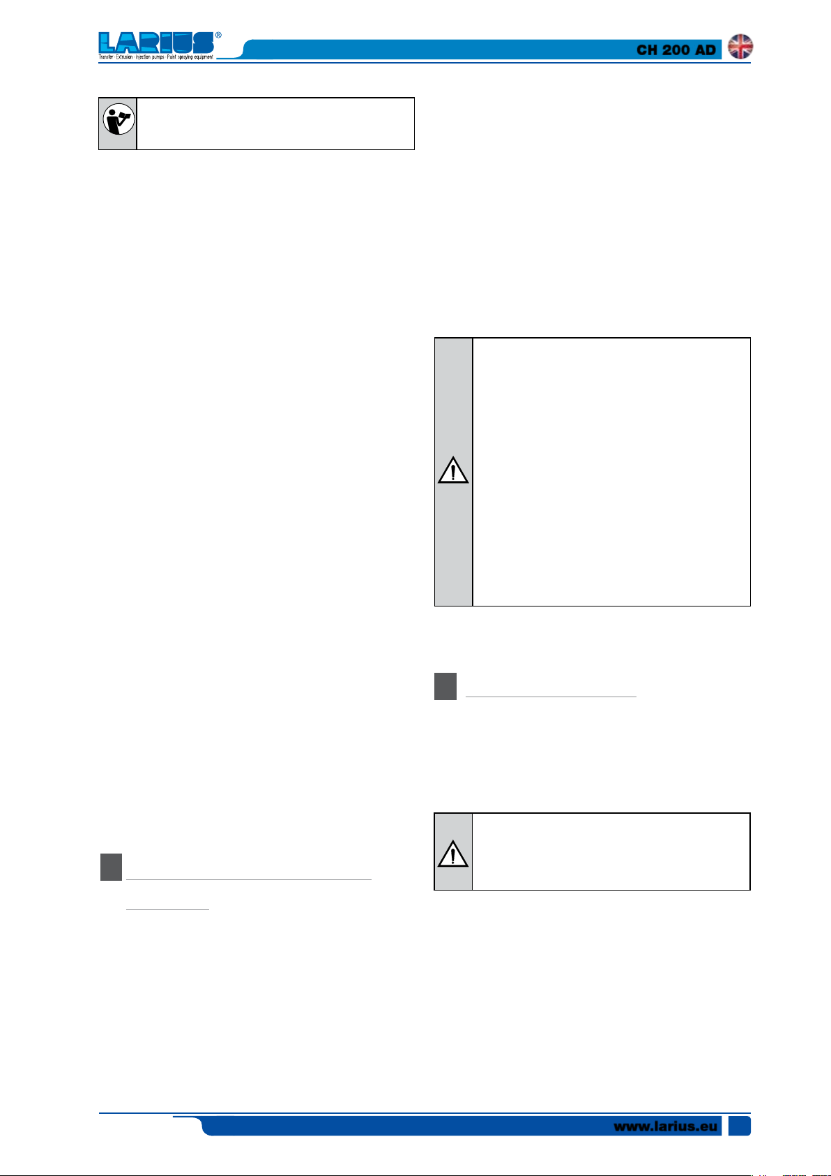
• Ensure the operator is correctly "grounded".
Do not use insulated gloves and plastic shoes. Antistatic
shoes are recommended.
• Do not enter the spray booth when the machine is operating. Before entering, ensure the locking system of the entire
system is working properly.
•
Facial masks and protective suits are recommended, when
you need to work in environments filled with powder.
• Keep the area surrounding the booth clean, for at least 5
metres.
• Keep the lighting lamps clean. Wash hands and face before
eating or drinking.
IF THE PRODUCT TO BE USED IS TOXIC, AVOID
INHALATION AND ONLY HANDLE USING PROTECTIVE GLOVES, PROTECTIVE GOOGLES AND
APPRORPIATE MASKS.
USE APPROPRIATE HEARING PROTECTION EQUIPMENT IF WORKING IN THE IMMEDIATE VICINITY
OF THE MACHINE.
Edit. 03 - 06/2019
HEALTH AND SAFETY
The powders:
• Can cause irritation to the eyes, hands and respiratory
system, after prolonged direct contact.
• Are toxic if inhaled.
• Are not flammable, but they can cause combustion if their
concentration in the air exceeds the allowable limit.
• Can form a conductor wire, that can be be switched on by
"open flames", heat or by electrical sparks.
www.larius.eu
7
CH 200 AD
Powder leakage:
clean with suction tube. Do not sweep.
Fire:
insulate electrical appliances and use foam.
Contact with eyes:
wash with running water and appropriate medicines.
Inhalation:
go outdoors. Put on clean clothes. If case of respiratory difficulty, seek immediate medical attention.
Ingestion:
provide immediate medical care.
• Distance between the electrode and the piece being pro-
The safety device of the LARIUS CH 200 electrostatic
Therefore it would be wrong to get too close to narrow
CONDITIONS OF GUARANTEE
The conditions of guarantee do not apply in the
following situations:
- improper washing and cleaning of components
causing malfunction, wear or damage to the
equipment or any of its parts;
- improper use of the equipment;
- use that does not conform with applicable national legislation;
- incorrect or faulty installation;
- modifications, interventions and maintenance that
have not been authorised by the manufacturer;
- use of non-original spare parts or parts that do
not correspond to the specific model;
- total or partial non-compliance with the instructions provided.
• The operator must wear conductive shoes (leather), no
cessed.
system, when below 20mm, causes a reduction in charging voltage that is so strong that the particles of sprayed
powder are no longer charged.
points in order to obtain better penetration.
gloves, as the operator's ground connection is established
through the metal plate on the handle of the spray gun.
leather
NO
• The powder tube must not be twisted or bent in any way.
CORRECT USE OF THE
F
SYSTEM
The machine described in this manual constitutes a complete
and autonomous unit for the application of powder coatings.
Correct use of the machine allows for the full exploitation of the
performance that is able to provide in conditions of complete
operator safety.
To achieve this, carefully observe the instructions provided below:
• Grounding of all mechanical parts, including the frame of
the machine and, of course, the piece being processed.
www.larius.eu
8
Edit. 03 - 06/2019
CH 200 AD
Follow the instructions included in the use and
maintenance manual.
• Verify the integrity of the components and parts of the
machine.
• Observe the instructions and warnings provided on the
machine, the safety warning labels on the machine must
always be perfectly legible.
• Check the state of preservation (cleaning) and maintenance
of the machine and its main components.
• Check the correct operation of the pneumatic system and
the condition of the pipes and fittings.
• For all operations, always wear suitable clothing, in compliance with workplace safety regulations.
• Report any operating malfunctions (faulty operation, sus-
pected breakage, incorrect movements and noise that exceeds
normal limits) to the department manager and switch off
the machine.
• Observe the maintenance schedule and record, after each
check, any observations concerning the maintenance
operation performed.
• The powder must be stored in a cool and dry place, in sealed
containers that are subject to frequent stock turnover.
• The surfaces of the piece to be treated must be free of any
contaminating agents and correctly pretreated.
The compressed air must not contain water or oil.
•
The piece to be treated must be correctly secured and
•
properly grounded.
• The frames must provide good grounding for the piece.
• The temperature of the furnace must be correct in order
to polymerise perfectly.
• The powder feeders, the spray booth, and the recovery
system must be free of all contaminating agents and free
of any powder that is different than that chosen for use.
• Pre-treatment and firing checks must be carried out periodically during processing.
• All the recycled powder must be sieved and mixed with
new powder observing the recommended proportions.
• Do not use silicones or paints near the machine.
• Use of the machine by personnel who is not adequately
trained.
• Failure to comply with routine maintenance requirements
or maintenance operations performed improperly.
• Use of non-original or unsuitable spare parts.
• Modification or cancellation of safety device settings and/
or tampering with the various equipment.
• Perform inspection, maintenance or repair operations
without having switched off the machine.
• Make temporary repairs or carry out recovery interventions
that do not comply with the instructions.
The company LARIUS is not responsible for mechanical damage to persons caused by incorrect uses as
described above.
In the event the customer must use the machine
with materials different than those cited in the sales
contract or modify the operating parameters, the
customer must contact LARIUS for new operating
parameters and technologies.
It is recommended that the operator in charge of the
machine's operation and the person responsible for
its maintenance, keep the safety and control areas
and the access area to the parts of the hoist, free
of all obstacles and equipment.
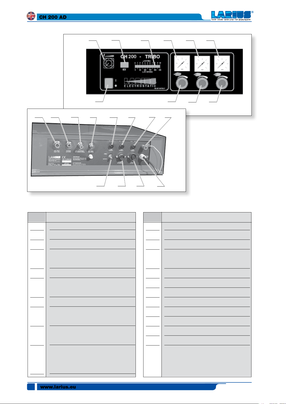
CONTROL PANEL
H
The operation, adjustment, and stoppage of the system, as well
as the instructions concerning correct operation, are managed
by the control panel positioned above.
Install a disconnecting switch with fuses upstream
of the main switch, in order to completely isolate
INCORRECT USE OF THE
G
the machine from the power supply network.
SYSTEM
OPERATING CONTROLS
The company LARIUS considers "incorrect use" of the machine
to be any use that is not described in the previous paragraph and:
• Do not point the spray gun jet at people.
• Use of improper or inadequate energy sources.
If modifications must be made to the machine, you must
contact LARIUS in order to obtain the most up-to-date
technology.
Edit. 03 - 06/2019
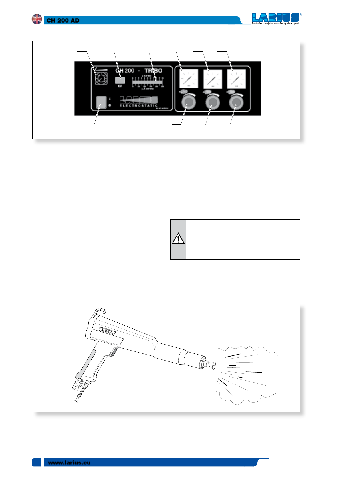
Buttons - Switches - Indicator lights - Potentiometers
The operating controls are located on the control panel and are
used directly by the operator during operation and to carry out
every maintenance or testing operation.
www.larius.eu
9
CH 200 AD
1 2 3 4 5 6
7
11 12 13 14 15 16 17 18
19 20 21 22
Pos.
1
2
Description
Kv adjusting potentiometer
Kv Digital indicator
Pos.
11
12
8
9 10
Description
Air inlet tube fixing attachment
Powder delivery air tube fixing connection
3
4
5
6
7
8
9
10
Led indicator µA
Pressure gauge for reading powder delivery air
pressure
.
Pressure gauge for press. additional air reading
Pressure gauge for reading "tribo air" pressure
and additional air pressure for cleaning CH 200
.
Main switch
Knob for adjusting powder delivery air pressure
.
Additional air pressure adjustment knob (to
evenly distribute the jet of powder)
.
Knob for adjusting the "tribo air" (increases the
electric effect) pressure and additional air for
cleaning the CH200 diffuser and rheophore
.
13
14
15
16
17
18
19
20
21
22
Fixing connection for additional air tube
Fixing connection for "tribo air" tube
and additional air tube for cleaning CH200
.
Main fuse (1A)
Solenoid fuse (2A)
Main PCB fuse (3.15 A)
Grounding cable fixing coupling
Selector for corona or electric painting
Outlet for automatic spray gun control cable
Outlet for spray gun supply cable
Power cable
www.larius.eu
10
Edit. 03 - 06/2019
CH 200 AD
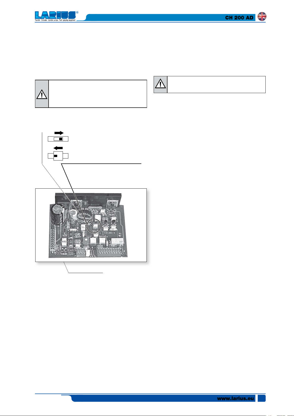
CURRENT OUPUT ADJUSTMENT µA
• Connect the machine to the compressed air supply using
The electronic processing board located inside the generator
is supplied complete with a current limiter device that allows,
if necessary, increasing the current without modifying the set
The tube must be connected to the (H3) filter.
voltage.
Increase the value of current supplied only if necessary. In normal working conditions with manual
spray guns it is recommended that the current
limiter be left enabled.
The humidity of the air must be less than 1 gr. of water p.p.m.
The quantity of air required depends on the operating pressure
(200-600 L/min.).
The compressor that supplies the air must be grounded sepa-
Current limiter excluded
Output current: min.180µA - max 250µA
rately with its own grounding cable.
• Connect the compressed air supply tube (H4) ø 10 mm to
Current limiter enabled
Output current: min.120µA - max.150µA
• Connect the powder supply tube (H6) and the additional air
a suitable type tube (H2), it must have a internal diameter
that is not less than 8 mm and must be able to withstand
a maximum pressure of 10 bar.
It is recommended that a shutter valve (ON-OFF)
be placed on the air supply line.
the rear of the rack's control panel.
tube (H7) to the powder supply pump and to the generator
(H5).
CIRCUIT BOARD
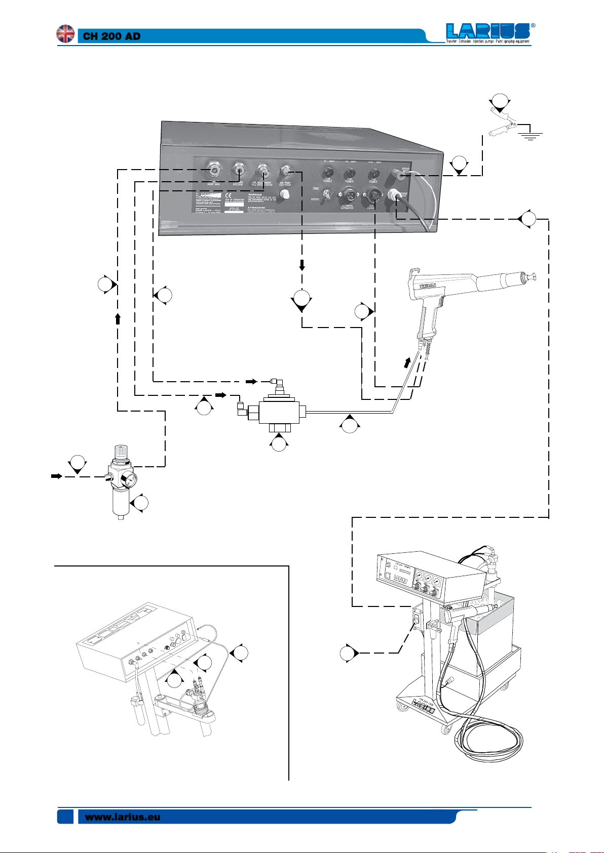
CONNECTIONS
• Make sure the system is equipped with a grounding connection
• Ensure that the mains voltage corresponds to that indicated
on the machine's nameplate.
• Connect the generator to the spray booth using a grounding cable (H8) and clamp (H9).
• Connect the vent tube (H10) to the tank cover and the spray
booth (or to a container).
Electrostatic spray gun
• Connect the power supply cable (H11) to the spray gun
and the generator.
• Connect the powder passage tube (H12) to the spray gun
and the powder delivery pump.
• Connect the additional air passage tube (H13) for clean-
ing the diffuser and rheophore to the spray gun and the
generator.
Triboelectric spray gun
• If spray guns are used which employ the triboelectric paint
system, remove the tribo air outlet cap and connect the
tube (H14) to the tribo spray gun.
• Make sure the switch is in the "0" position
.
• Connect the machine to the mains using the dedicated
cable (H1).
Edit. 03 - 06/2019
www.larius.eu
11
CH 200 AD
H10
H9
H3
H5
H4
H8
For tribo-electric spray gun
CH200 Additional air coupling
H7
H6
H14
H13
H12
110 - 220 V c.a.
Electrostatic spray gun
H2
www.larius.eu
12
H7
H8
H11
H1
110 - 220 V c.a.
Edit. 03 - 06/2019
CH 200 AD
OPERATION
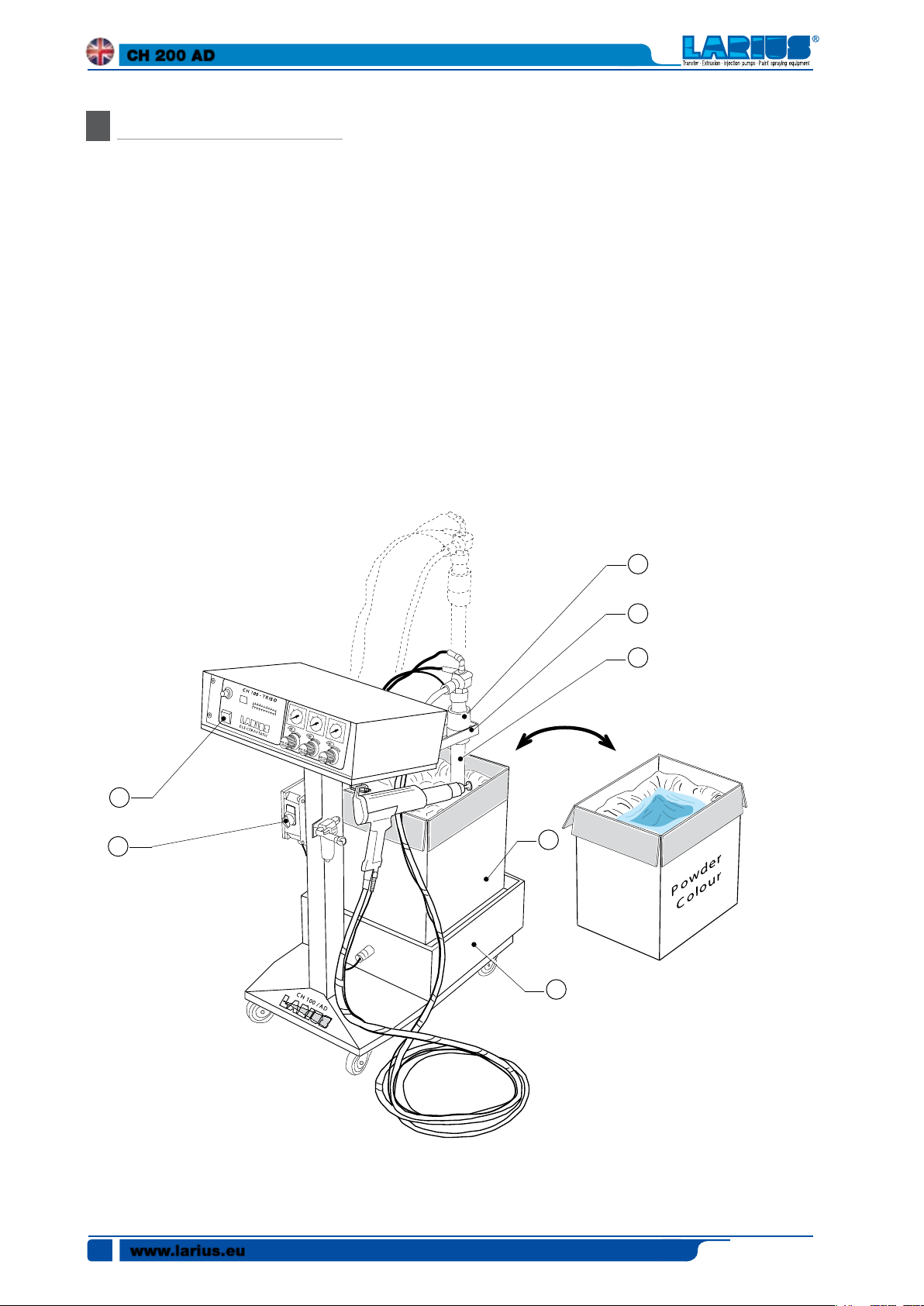
After having carried out all the electrical and pneumatic connections as described in the previous chapter, proceed as follows:
•
Turn the revolving arm (H15) in order to be able to position
the cardboard box (H16) containing the powder on the
vibrating surface (H17) as illustrated in the figure.
•
Lift up the powder suction tube (H18). Loosening the locking ring nut (H19), it is possible to slide the suction tube
along the revolving arm.
•
Turn the revolving arm (H15) and position it above the
powder container.
•
Lower the powder suction tube (H18) inside the container.
•
Open the air supply to the machine.
•
Press the main switch (H20) of the control panel to power
the generator.
•
Turn the switch (H21) of the electric vibrator to the "ON"
position.
The electric vibrator is activated each time the
spray gun trigger is pressed and it automatically
stops every time the trigger is released.
USE WITH CH 200 SPRAY GUN (corona effect)
To use with the CH 200 spray gun (corona effect),
make sure the selector (H17) is in the "CORONA"
position.
H22
• Point the spray gun inside the spray booth and hold down
the trigger to adjust the powder delivery setting.
• Adjust the air pressure delivered to the powder supply
pump (H18), using the regulator (H19) and reading the
value expressed in bar on the pressure gauge H20) (max
recommended values 3-4 bar).
H20
H19
H15
H18
H16
H21
H17
Edit. 03 - 06/2019
www.larius.eu
13
CH 200 AD
H29 H30 H31 H24 H26 H28
H32
• Adjust the powder diffusion range of the spray gun using
H23
• Point the spray gun at the object to be painted (recomthe knob (H21) and reading the value expressed in bar on
the pressure gauge (H22), (recommended values 0.5-2 bar);
however, this value must always be less than the supply
air pressure (pressure gauge H23); once adjustment is
complete, release the spray gun trigger.
• Adjust the flow of the additional air that controls the cleaning of the diffuser and charging rheophore. Using the knob
(H24) and checking the pressure gauge (H25) set the outlet
air pressure to the recommended values between 0.5-1 bar.
Depending on the amount of powder delivered, ensure the
cleaning cone cleans the powder residue from the affected
areas.
• Using the potentiometer (H26) select the desired voltage
value (0 -100 kv) read the set value on the digital display
(H27).
H25 H27
mended distance 15-20 cm) and press the trigger, which
will start to deliver powder, as well as high voltage; the
value of current, expressed in microamperes (max 250 µA)
can be read on the lit indicator (H3).
Protect the spray gun from all violent mechanical
action. Repeated impacts and shocks of considerable intensity, while not altering the outer integrity
of the spray gun, may cause internal damage and
cause the spray gun to become unusable.
www.larius.eu
14
Edit. 03 - 06/2019
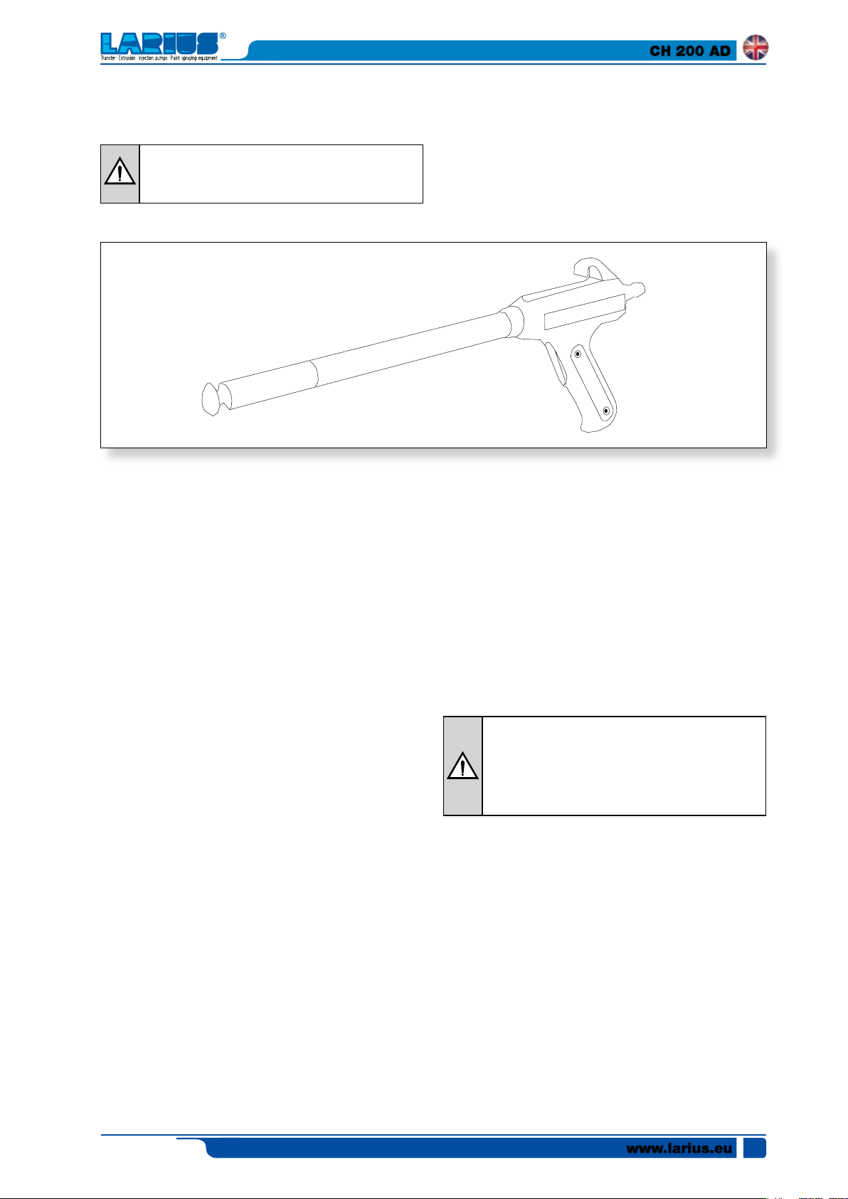
USE WITH THE TRIBOELECTRIC SPRAY GUN
To use with the triboelectric spray gun, make sure
the selector (H22) is in the "TRIBO" position.
CH 200 AD
• Point the spray gun at the object to be painted (recom-
If the pressure is increased, the triboelectric effect is also
mended distance 15-20 cm) and press the trigger, which
will start to deliver powder, as well as high voltage; the
The electrostatic charge value can be read on the luminous
value of current, expressed in microamperes (max 250 µA)
can be read on the lit indicator (H28).
• Adjust the air pressure to the powder supply pump (H29),
by turning the regulator (H30) and reading the value expressed in bar displayed on the pressure gauge (H23)
(recommended max values 3-4 bar).
At this point, release the spray gun trigger.
Point the spray gun at the object to be pained (recommended
distance 10-20 cm) and press the spray gun trigger, which will
start to deliver powder.
The value of the current expressed in µA (max 10 µA) can be
read on the luminous indicator (H28).
• Adjust the powder diffusion range of the spray gun using
the knob (H29) and reading the value expressed in bar on
the pressure gauge (H22), (recommended values 0.5-2 bar);
however, this value must always be less than the supply
air pressure (pressure gauge H23).
• Adjust the "tribo air" pressure using the knob (H24) and
reading the pressure value set on the pressure gauge (H25).
increased.
indicator (H28) located on the generator.
Protect the spray gun from all violent mechanical
action. Repeated impacts and shocks of considerable intensity, while not altering the outer integrity
of the spray gun, may cause internal damage and
cause the spray gun to become unusable.
Edit. 03 - 06/2019
www.larius.eu
15
CH 200 AD
CYCLICAL ROUTINE MAINTENANCE
I
Before performing any maintenance or cleaning operation disconnect the electric and pneumatic power supply.
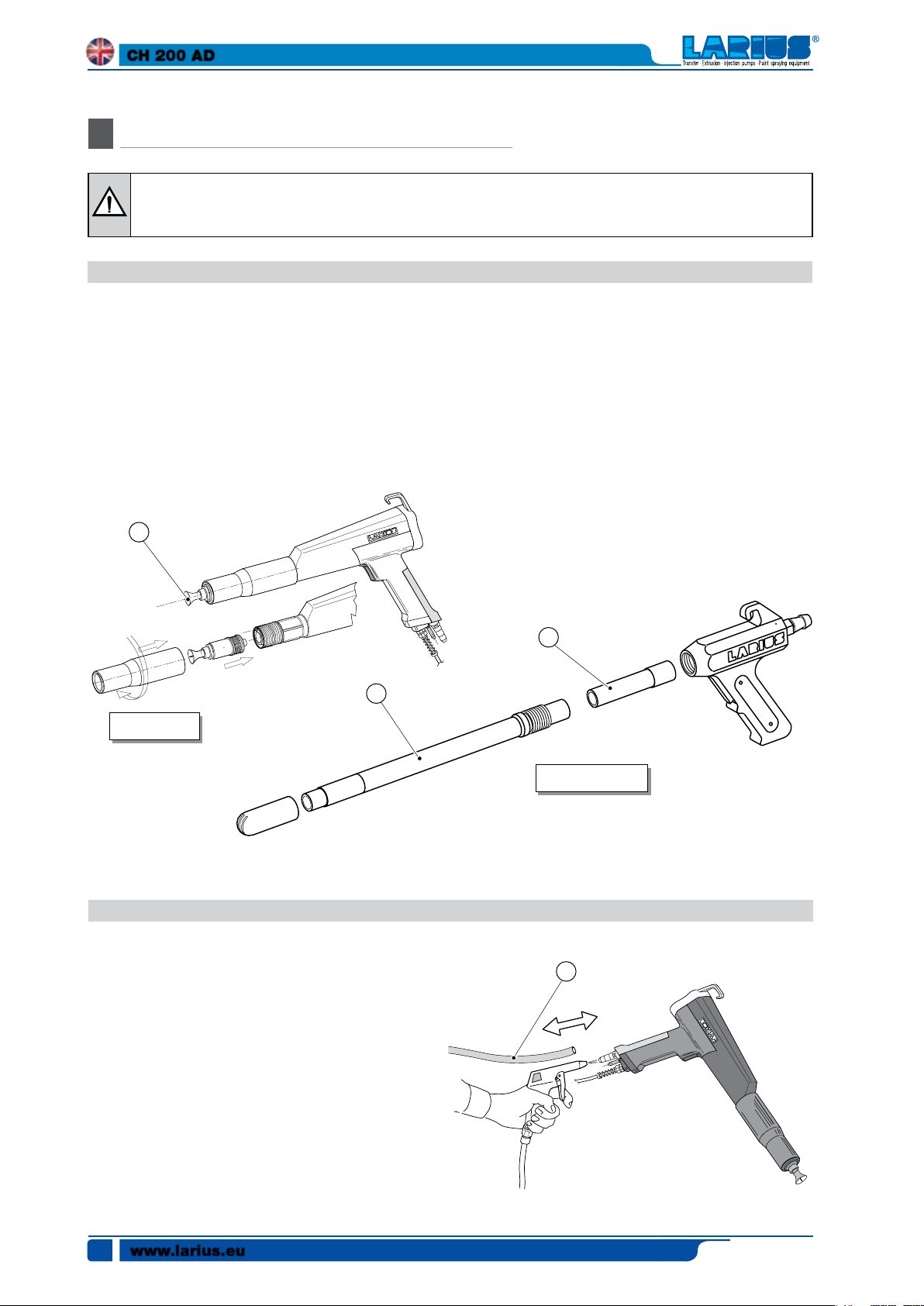
EVERY 8 HOURS AND/OR AT EVERY COLOUR CHANGE
Cleaning the CH200 spray gun
• Disconnect the powder supply tube and remove the nozzle
(I1) of the spray gun.
• Clean the inner part of the spray gun and nozzle with a jet
of compressed air. If necessary, use the brush supplied to
clean the spray gun.
I1
I2
Gun CH 200
Cleaning the triboelectric spray gun
• Disconnect the powder supply tube and remove the nozzle. Clean the inner part of the spray gun and nozzle with
a jet of compressed air.
• If removing the triboelectric spray gun is necessary
Using your hands, unscrew the charge tube (I2) from the
spray gun body. Using your hands, slip off the diffuser (I3).
Remove the nozzle.
I3
Tribo-electric gun
EVERY 40 - 80 HOURS AND/OR AT EVERY COLOUR CHANGE
Cleaning the powder supply tube
• Disconnect the powder supply tube (I4) from the tank
and spray gun and blow in compressed air to remove any
remaining powder residue.
Ensure the powder passage tube is not cracked, bent or
damaged in any way.
www.larius.eu
16
I4
Edit. 03 - 06/2019

EVERY 40 - 80 HOURS
Check venturi diffuser
• Check the wear of the powder delivery pump's Venturi
diffuser (I5).
A new diffuser hole is 4.8mm; with wear the hole's diameter
CH 200 AD
increases, decreasing the Venturi effect and, when the hole
reaches 8 mm, the diffuser must be replaced.
For highly abrasive materials use tungsten carbide diffus-
ers.
I5
EVERY 40 - 80 HOURS
Cleaning the pressure reducer filter
To ensure proper machine operation, follow these rules:
• Ensure proper operation of the pressure reducer lter.
Ensure there is no condensation build-up inside the cup.
If necessary, periodically discharge the condensation by
unscrewing the bleed screw (I6) under the filter cup; the
pressure inside the cup will cause the expulsion of the
condensation.
• Periodically clean the lter cartridge in order to prevent
system performance losses.
Wash the cup with water and dry with a jet of compressed
air.
Before removing the cup close the compressed
air supply.
Adjusting the pressure
Adjust the pressure by turning the knob located on the upper
part of the reducer.
To increase it turn clockwise (+).
To decrease it turn counter clockwise (-).
Do not power the pneumatic system with compressed air that
is excessively dirty or that contains aggressive liquids.
Edit. 03 - 06/2019
I6
www.larius.eu
17
CH 200 AD
COLOUR CHANGING
J
• Remove the box and replace it with that of the new colour
which you intend to use, correctly placing it on the shaking
table(J5).
The design of the CH 200/AD unit allows for quick colour
changing, directly using the original box containing the powder.
To change the colour, proceed as follows:
• Disconnect the electric and pneumatic mains supply that
powers the machine.
• Turn the revolving arm (J1) in order to remove the cardboard
box (J2).
• Lift up the powder suction tube (J3). Loosening the locking
ring nut (J4) it is possible to slide the suction tube along
the revolving arm.
• Turn the revolving arm (J1) and position it above the powder
container.
• Lower the (J3) powder suction tube inside the container.
• Open the air supply to the machine.
• Press the main switch (J6) of the control panel to power
the generator.
• Turn the switch (J7) of the electric vibrator to the "ON"
position.
J5
J1
J4
J6
J7
www.larius.eu
18
J2
J3
Edit. 03 - 06/2019
PROBLEMS AND SOLUTIONS
K
CH 200 AD
Problem
• Electrical charges between the
spray gun nozzle and the object
to be painted
• The machine does not start up
after the ON-OFF switch has been
pressed
• The rack switches on but the Kv
display is not working
• The kv display lights up but the kv
scale does not increase when the
potentiometer is turned
• Excessive voltage;
• For CH 200 spray gun: excessive
• For CH 200 spray gun: nozzle dam-
• The object to be painted is not prop-
• For CH 200 spray gun the voltage
• No mains voltage;
• Fuse 1A is defective;
• Fuse 3.15A is defective;
• Processing board defective;
• KV control potentiometer defective,
Cause
electric current;
aged;
erly electrically grounded;
multiplier is defective;
processing board defective or display
board defective
Solution
• For CH 200 spray gun: decrease
the voltage using the rack's potentiometer;
• For spray gun: decrease the air
pressure;
• Reset the current limiter switch
located on the processing board ;
• Replace the nozzle;
• With a tester or similar instrument
check the electrical grounding of
the piece holder hooks. If necessary, clean the piece holder hooks;
• Replace the voltage multiplier;
• Check the electric supply line;
• Replace the 1A fuse;
• Replace the 3.15A fuse;
• Replace the processing board;
• Proceed as follows:
- Disconnect the power supply
- Remove the four fixing screws
and slip the rack off the CH
200-tribo machine's protective
cover.
- Remove the connector marked
j3 from the processing board.
- Using a tester (or similar instru-
ment capable of measuring
electrical resistance) check the
integrity of the potentiometer:
connect a tip of the tester to
the central terminal of the potentiometer and the other tip to
one of the two side terminals.
Turning the potentiometer knob,
the resistance value read on the
tester varies from 0 to 1 KΩ, approximately.
- If a negative result is obtained,
replace the potentiometer.
• The machine is working but the
powder does not come out of
the spray gun when the trigger is
pressed.
Edit. 03 - 06/2019
• No powder;
• Powder delivery pump clogged;
• The air pressure is not sufficient to
• Fuse 2 A is defective;
• Spray gun-generator cable incor-
adjust powder delivery;
rectly connected or damaged;
• Add powder;
• Remove the powder delivery pump
and clean the passages;
• Increase the air pressure to adjust
powder delivery;
• Replace the 2 A fuse;
• Check the connections; verify the
continuity of the cable connections
using a tester and, if necessary,
replace it;
www.larius.eu
19

CH 200 AD
Problem
• Rapid wear of Venturi diffuser
• The powder puffs out of the spray
gun
• Insufficient powder flow
Cause
• No mains voltage;
• Worn or partially clogged Venturi;
• The additional air pressure is exces-
sive (rack central regulator) or the
ratio between this and the powder
delivery air pressure is incorrect (left
rack regulator);
• The tank's fluid bed air pressure is
excessive or insufficient;
• The unidirectional valves of the powder pump are partially clogged;
• Powder passage tube too short or
with excessive inner diameter;
• The air pressure for adjusting the
powder delivery is insufficient;
• Use a hard metal Venturi diffuser
• Clean and/or replace the Venturi;
• Decrease the additional air pres-
Important: The additional air pres-
• Adjust the fluid bed air pressure
• Clean and/or replace the unidirec-
• Use the powder passage tube
• Increase the air pressure to adjust
Solution
(code 5296/A);
sure and/or increase the powder
delivery air pressure.
sure must always be lower than the
powder delivery air pressure;
(recommended pressure value:
0.5-1bar);
tional valves;
supplied or a tube with an inner
diameter that is no greater than
12mm and with a length no less
than 5 metres;
powder delivery;
• The powder is not sufficiently
electrostatically charged and/or
does not “cover”
•
The powder "cover" but the µA
scale does not increase
• The powder is too wet and is sucked
up by the powder pump with difficulty;
• Worn or partially clogged Venturi;
• The additional air pressure (central
regulator rack) is excessive;
• The additional nozzle cleaning air
pressure is excessive;
• The piece to be painted is not properly
electrically grounded;
• The powder is not suited for use with
a corona and/or triboelectric system;
• Only for triboelectric spray gun: •
The "tribo" air pressure (central
regulator rack) is excessive;
• For CH 200 spray gun: nozzle damaged and/or dirty;
• For triboelectric spray gun: charge
tube dirty and/or damaged;
• Display board not working;
• Check the compressed air supply
line. Install an air dryer if necessary;
• Clean and/or replace the Venturi;
• Decrease the additional air pres-
sure;
• Decrease the additional air pressure;
• With a tester or similar instrument
check the electrical grounding of
the piece holder hooks. If necessary, clean the piece holder hooks;
• Consult the powder supplier;
• Increase the "tribo" air pressure to
increase the triboelectric effect;
• Clean and/or replace the nozzle;
• Clean and/or replace the charge
tube;
• Replace the display board;
www.larius.eu
20
• For triboelectric spray gun: tribocorona switch set to"corona";
• Move the switch to "tribo";
Edit. 03 - 06/2019

CH 200 AD
Problem
• For triboelectric spray gun: spray
• For triboelectric spray gun: process-
• The powder does not charge and
does not "cover"
• The machine is working but the
powder does not come out of
the spray gun when the trigger is
pressed.
• The powder is not suited for use with
• For CH 200 spray gun: processing
• For CH 200 spray gun: tribo-corona
• For CH 200 spray gun: nozzle elec-
• For CH 200 spray gun: the voltage
• Solenoid valve or processing board
• Spray gun button defective
Cause
• Check the connections; verify the
gun-generator cable not connected
properly or damaged;
• Replace the processing board;
ing board damaged.
• Consult the powder supplier;
a corona and/or triboelectric system;
• Replace the processing board;
board damaged ;
• Move the switch to "corona";
switch on "tribo";
• Correctly secure the nozzle and/or
trodes are broken or nozzle is not
secured correctly to the spray gun;
• Replace the voltage multiplier;
multiplier is defective;
• Replace the solenoid and/or pronot working;
• For triboelectric spray gun:
• For CH 200 spray gun:
Solution
continuity of the cable connections
using a tester and, if necessary,
replace it;
replace the nozzle;
cessing board;
- Disconnect the spray gungenerator connecting cable from
the generator;
- With a tester (or similar instrument capable of measuring
electrical resistance) verify the
electrical continuity between the
terminals marked with a 1 and
the connector when the spray
gun trigger is pressed;
- If the result of the test is negative,
proceed with replacing, in order,
the trigger lever, then the trigger
body, and lastly both parts;
- Disconnect the spray gungenerator connecting cable from
the generator;
- With a tester (or similar instrument capable of measuring
electrical resistance) verify the
electrical continuity between the
terminals marked with a 1 and
the connector when the spray
gun trigger is pressed;
- If the result of the test is negative,
proceed with replacing, in order,
the trigger, then the reed block,
and lastly both parts;
Edit. 03 - 06/2019
www.larius.eu
21

CH 200 AD
Problem
• The machine is working and the
powder comes out of the spray
without the trigger.
• Spray gun button defective
Cause
Solution
• Replace the solenoid and/or processing board;
• For triboelectric spray gun:
- Disconnect the spray gungenerator connecting cable from
the generator;
- With a tester (or similar instrument capable of measuring
electrical resistance) verify the
electrical continuity between the
terminals marked with a 1 and
the connector when the spray
gun trigger is pressed;
- If the result of the test is negative,
proceed with replacing, in order,
the trigger lever, then the trigger
body, and lastly both parts;
• For CH 200 spray gun:
- Disconnect the spray gungenerator connecting cable from
the generator;
- With a tester (or similar instrument capable of measuring
electrical resistance) verify the
electrical continuity between the
terminals marked with a 1 and
the connector when the spray
gun trigger is pressed;
- If the result of the test is negative,
proceed with replacing, in order,
the trigger, then the reed block,
and lastly both parts;
• The machine is working but the
electro-vibrator fails to switch
on when the spray gun trigger is
pressed.
Always disconnect the power supply and discharge the pressure before performing any checks or replacing parts
of the pump (follow the "correct pressure relief procedure").
• Vibrator switch in the “OFF” position;
• Electro-vibrator defective.
• Turn the switch to the “ON” position;
• Replace the electro-vibrator.
www.larius.eu
22
Edit. 03 - 06/2019

SPARE PARTS
CH 200 AD
ELECTRO-PNEUMATIC
O
N
GENERATOR
pag.28
CH200-AD FRAME SPARE
O
M
PARTS
pag.26
POWDER DELIVERY PUMP SPARE PARTS
O
Z
RIF.5505
pag.41
CH 200 MANUAL SPRAY GUN RIF.9700
O
O
pag.30
CH 200 AUTOMATIC SPARY GUN RIF. 9705
O
P
pag.32
AUTOMATIC AND MANUAL TRIBO SPRAY
O
Q
GUN SPARE PARTS
pag.34
CONE JET NOZZLE SPARE PARTS
O
R
FOR CH 200
pag.36
CH200-AD SHAKING TABLE
O
L
SPARE PARTS
pag.24
ACCESSORIES
Y
pag.42
CONE JET NOZZLE WITH EXTENTION
O
S
SPARE PARTS FOR CH 200
pag.37
FAN NOZZLE SPARE PARTS FOR CH 200
O
T
pag.38
HIGH PERFORMANCE NOZZLE SPARE
O
U
PARTS FOR CH 200
pag.39
MULTI-DIFFUSION NOZZLE SPARE PARTS
O
V
FOR CH 200
pag.40
Edit. 03 - 06/2019
www.larius.eu
23

CH 200 AD
CH 200-AD SHAKING TABLE SPARE PARTS
L
WARNING: Always indicate code and quantity for each part required.
www.larius.eu
24
Edit. 03 - 06/2019
CH 200 AD
Pos. Pos.
1
2
3
4
5
6
6
7
8
Code Description Code Description
510425
5877
5725
5726
5728
5723
5757
95063
8042
Screw
Shaking table
Washer
Screw
Vibration damper
Vibrator 220 V
Vibrator 110 V
Washer
Self-locking nut
9
10
11
12
13
14
15
16
17
5727
5878
5729
54003
54004
5583
5738
91026
5582
Screw
Shaking table base
cable gland
Washer
Screw
Screw
Trolley base
Nut
Wheel
Edit. 03 - 06/2019
www.larius.eu
25

CH 200 AD
M FRAME SPARE PARTS CH 200-AD
WARNING: Always indicate code and quantity for each part required.
www.larius.eu
26
Edit. 03 - 06/2019

CH 200 AD
Pos. Pos.
.
1
2
3
4
5
6
7
8
9
10
11
12
13
Code Description Code Description
5710
5875
5591
5778
5583
95063
8042
5746
5747
32029
5876
91154
96030
34008
Complete rack support
Generator cover
Screw
Slotted nut
Screw
Washer
Nut
Screw
Washer
Nut
Generator support
Electric box
Washer
Screw
18
19
20
21
22
23
24
25
26
27
28
29
30
31
5751
5750
5749
5755
5756
34009
7059
5765
5768
5708
5743
5745
11719
5741
Washer
Friction washer di frizione
Block for swivel arm
Screw
Nut
Washer
Screw
Grounding cable
Self-tapping screw
Powder suction complete hose
Upper fitting
Throttling
Automatic fitting
Suction hose
14
15
16
17
5752
5754
5753
5748
Tube locking ring nut
Guiding support
Suction tube guide
Swivel arm
32
33
34
5740
5742
5744
Powder hose
Lower fitting
Filter
Edit. 03 - 06/2019
www.larius.eu
27

CH 200 AD
N
ELECTRO-PNEUMATIC GENERATOR
ATTENZIONE: per ogni particolare richiesto indicare sempre il Code e la quantità.
www.larius.eu
28
Edit. 03 - 06/2019

CH 200 AD
Pos. Code Description
5920
-
Electro-pneumatic generator
preset for CH 200 spray gun and
.
-
.
-
.
1
2
.
.
5101
.
5922
.
5929
5603
.
5925
.
5927
.
Larius Tribo
Electro-pneumatic generator
preset for CH 200 spray gun
Electro-pneumatic generator
preset for Larius Tribo spray gun
Display board
Data processing board for
CH 200
Data processing board for CH
1200 and Tribo
Data processing board for tribo-
electric
Q.ty
Pos. Code Description Q.ty
-
22
23
.-
24
.
25
-
26
.
27
1
28
1
29
.
30
1
.
31
1
.
32
9149
5937
.
4018
5349
5348
5676
5347
22016
5609
.
5649
.
5353
Fuse 1A
Connector for fixing automatic
.
control cable
Silencer
Fitting for tube ø 6
Fitting for tube ø 8
Fitting for tube ø 6
Fitting for tube ø 10
1/4" Fitting for tube ø 8
Solenoid valve complete with coil,
.
connector, fittings
Solenoid valve complete with coil
.
and connector
Solenoid valve
1
1
.
1
1
1
1
1
1
1
.
1
.
1
3
4
5
6
7
9
12
13
14
17
18
19
5931
5932
5933
5346
5341
5787
.
5789
22015
.
22014
.
5566
5158
5934
Potentiometer
Potentiometer knob
ON-OFF switch
1/8" Fitting for tube ø 4
Pressure gauge 0-6 bar
Regulator complete with fittings
.
Air regulator 0-4 bar
1/4" Revolving elbow fitting tube
.
ø 8
1/8" Revolving elbow fitting tube
.
ø 4
Grounding terminal
Fuse 3.15 A
Power supply cable
1
33
1
34
1
35
3
36
3
37
3
38
.
39
3.
40
6
41
42
3
43
.
.1
1
1
5627
5628
510019
4039
5597
5359
8032
5255
4006
510020
5935
Solenoid coil
Solenoid coil connector
1/4" Fitting ø 8
Elbow for tube ø 8
1/4" Fitting ø 10
Elbow for tube ø 10
1/4” fitting
1/4 Elbow fitting
1/4" Fitting for tube ø 8
"T" Fitting for tube ø 8
Tribo-corona switch
1
2
1
1
1
3
1
2
1
1
.
20
21
Edit. 03 - 06/2019
9148
5936
.
gland clamp
Fuse 2 A
Spray gun cable fixing connector
.
1
1
www.larius.eu
29
CH 200 AD
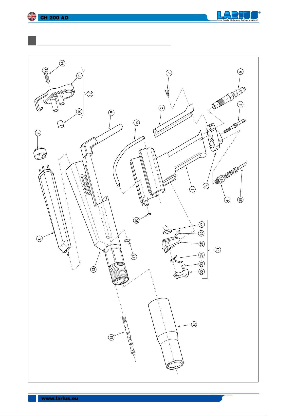
CH 200 MANUAL SPRAY GUN REF.9700
O
ATTENTION: for each part required always indicate the code and quantity.
www.larius.eu
30
Edit. 03 - 06/2019
CH 200 AD
Pos. Code Description
9700
1*
2*
3*
4*
5
6
7*
8
9
10
11
.
9752
9756
9755
9849
9762
.
.
9760
.
.
9819
9820
9832
9754
9753
CH 200 manual Spray Gun
Handgrip
Grounding cover
Terminal block
cable gland
Air passage tube fixing con-
nection
Powder passage tube fixing
connection
Screw
Multiplier
Connector
Check glass
Rear cap
Pos. Code Description Q.ty
Q.ty
1
14
1
15
1
16
1
17
1
18
1
19*
.
20
1
21*
.
22
1
23
1
24
1
25
1
26
1
27
9803
9770
9779
95326
9772
9761
4077
9763
9765
5055
9792
9764
9766
9769
Screw
Electric resistance assembly
Ring nut
O-ring
Powder passage tube
Air tube
O-ring
Complete trigger
Trigger
Magnet
Spring
Trigger support
Trigger pin
Reed sensor
1
1
1
1
1
1
1
1
1
1
1
1
1
1
12
13
9703
9751
Complete rear cap
Complete front body
* Complete handgrip code 9945
1
28*
9900
Cable
1
2
Edit. 03 - 06/2019
www.larius.eu
31
CH 200 AD
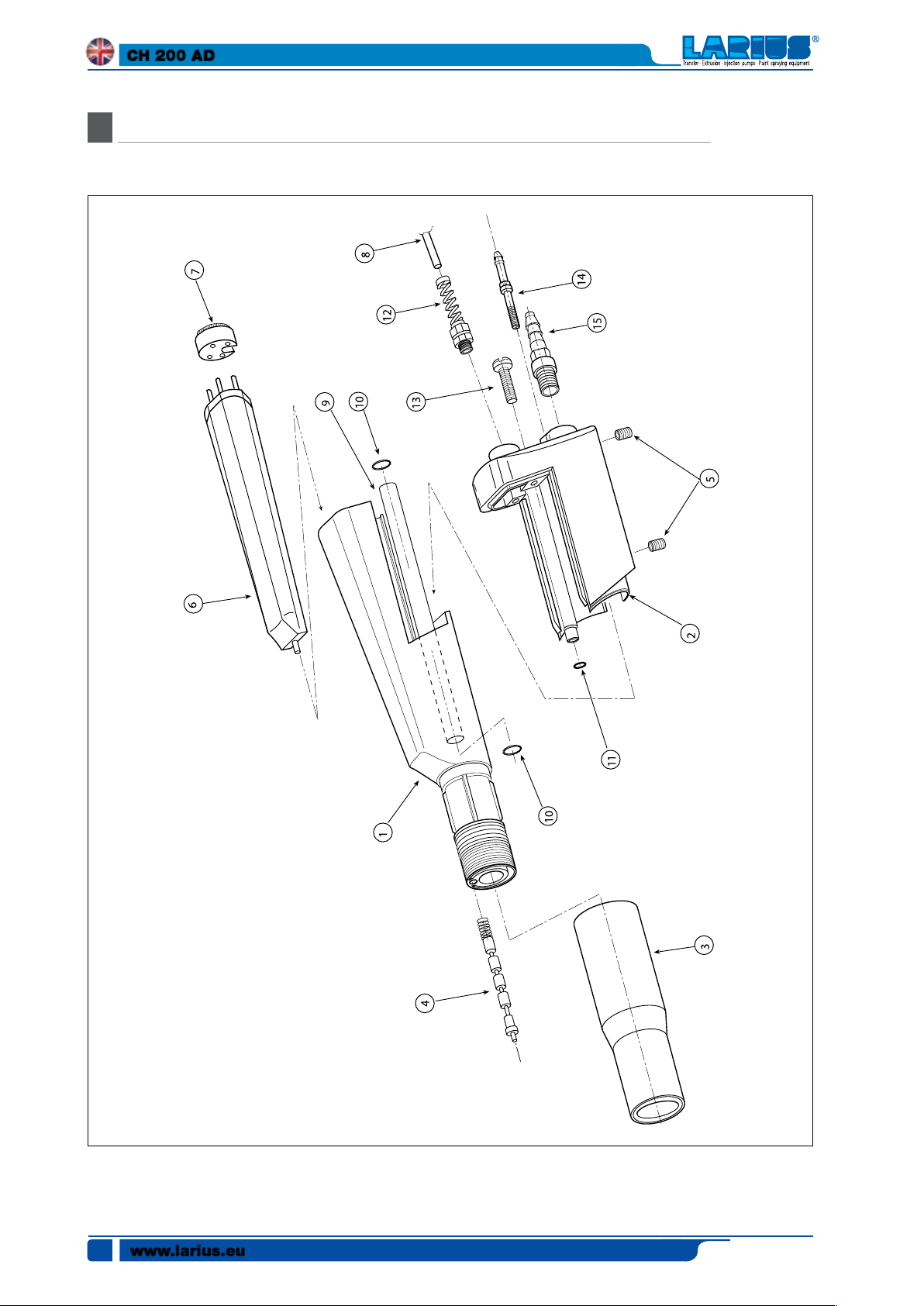
SPARE PARTS FOR AUTOMATIC GUN CH 200 REF. 9705
P
ATTENTION: for each part required always indicate the code and quantity.
www.larius.eu
32
Edit. 03 - 06/2019
CH 200 AD
Pos. Code Description
9705
1
2*
3
4
5*
6
7
.
9751
9801
9779
9770
5546
9820
9832
Automatic spray gun
Complete front body
Rear cap
Ring
Electric resistance assembly
Threaded inserts
Multiplier
Connector
* Complete rear cap code 9950
Pos. Code Description Q.ty
Q.ty
-
8*
1
1
10
1
11
4
12*
1
13
1
14
1
15
9900
9802
9
95326
4077
9849
9803
9804
5529
Cable
Powder passage tube
O-ring
O-ring
Cable gland
Screw
Air fitting
Powder inlet fitting
1
2
1
1
2
1
1
1
Edit. 03 - 06/2019
www.larius.eu
33

CH 200 AD
SPARE PARTS FOR AUTOM. AND MANUAL TRIBO SPRAY GUN
Q
ATTENTION: for each part required always indicate the code and quantity.
www.larius.eu
34
Edit. 03 - 06/2019

CH 200 AD
Pos. Code Description
15200
-
15203
-
15211
1
15260
2
15226
3
.
15225
4
.
15268
5
15264
6
15265
7
15220
8
15217
9
Manual triboelectric spray gun
Automatic triboelectric spray gun
Automatic spray gun body
Manual spray gun body
Air passage tube fixing
.
connection
Powder passage tube fixing
.
connection
Grounding plate
Trigger lever
Trigger body
Diffuser
Spacer cone
Pos. Code Description Q.ty
Q.ty
10
11
12
13
14
15
16
17
17
18
18
19
15262
15237
15223
15224
15216
15280
15298
15297
15296
15290
15293
15295
15221
.
Central rod length 400 mm
Tube
Spacer
Tube
Diffuser holder fitting
Complete charging tube
Bush for cone jet nozzle
Diffuser diameter 22mm
Diffuser diameter 26 mm
Flat jet nozzle
30° flat jet nozzle
Nozzle with holes for round jet
Nozzle with 1 flat notch
-
-
1
1
1
.
1
.
2
1
1
1
1
1
1
1
1
1
1
1
1
1
1
*
*
*
* Upon request
Edit. 03 - 06/2019
www.larius.eu
35

CH 200 AD
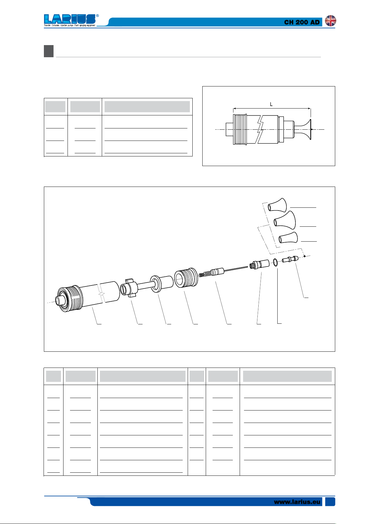
CONE JET NOZZLE SPARE PARTS FOR CH 200
R
L (mm)
Code Description
971590
Standard nozzle
10
11
9
1
Pos. Pos.
1
2
3
4
5
6
36
Code Description Code Description
9865
9866
9861
9862
9855
9856
www.larius.eu
Complete nozzle body (standard)
Complete electrode holder
Bushing
Ring
Complete electrode
Diffuser holder tip
2
3
4
7
8
9
10
11
9895
9857
9858
9859
9860
5
O-ring
Air diffuser
Diffuser ø 16
Diffuser ø 24
Diffuser ø 32
8
6
7
Edit. 03 - 06/2019
CH 200 AD
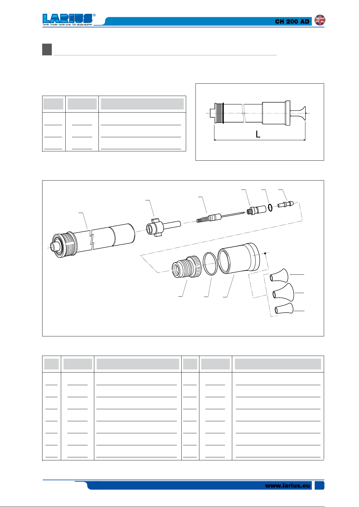
SPARE PARTS FOR CONE JET NOZZLE WITH EXTENSION FOR CH 200
S
L (mm)
160
310
570
Code Description
9720
9725
9730
Medium nozzle
Long nozzle
Extra-long nozzle
9
10
8
1
Pos. Pos.
1
1
1
2
3
4
5
Code Description Code Description
9885
9886
9887
9866
9861
9862
9855
Complete nozzle body (medium)
Complete nozzle body (long)
Complete nozzle body (extra long)
Complete electrode holder
Bushing
Ring nut
Complete electrode
2
3
6
7
8
9
10
11
11
7
9856
9895
9858
9859
9860
9857
5
Diffuser holder tip
O-ring
Diffuser ø 16
Diffuser ø 24
Diffuser ø 32
Air diffuser
4
6
Edit. 03 - 06/2019
www.larius.eu
37

CH 200 AD
FAN NOZZLE SPARE PARTS FOR CH 200
T
L (mm)
90
160
310
570
Code Description
9735
9740
9745
9750
Standard nozzle
Medium nozzle
Long nozzle
Extra-long nozzle
1
Pos. Pos.
1
1
1
1
2
Code Description Code Description
9855
9885
9886
9887
9866
Standard nozzle body
Complete nozzle body (medium)
Complete nozzle body (long)
Complete nozzle body (extra long)
Complete electrode holder
2 3
3
4
5
6
9890
9891
9892
9862
4
Complete electrode
Tip
Fan nozzle
Ring
5
6
www.larius.eu
38
Edit. 03 - 06/2019
HIGH PERFORMANCE NOZZLE SPARE PARTS FOR CH 200
U
CH 200 AD
L (mm)
150
300
560
Code Description
9815
9816
9817
Medium nozzle
Long nozzle
Extra-long nozzle
2
1
4
5 6
3
8
10
Pos. Pos.
1
1
1
2
3
4
5
Code Description Code Description
9920
9921
9922
9923
9855
9856
9895
Complete nozzle body (medium)
Complete nozzle body (long)
Complete nozzle body (extra long)
Complete electrode holder
Complete central electrode
diffuser support
O-ring
6
7
8
9
10
11
12
11
12
9857
9858
9859
9860
9925
11105
5832
9
7
Air diffuser
Diffuser ø 16
Diffuser ø 24
Diffuser ø 32
Rheophore support
O-ring
Jet adjustment bush
Edit. 03 - 06/2019
www.larius.eu
39

CH 200 AD
MULTI-DIFFUSION NOZZLE SPARE PARTS FOR CH 200
V
1
2 3
4
5
6
7
Pos. Pos.
1
1
.
1
.
1
.
40
Code Description Code Description
9930
9936
9937
.
9938
.
9939
.
www.larius.eu
Complete multi-diffusion nozzle
Standard diffuser body 12 pcs.
Diffuser body with a central notch
(upon request)
Diffuser body with two 30° inclined
notches (upon request)
Diffuser body with two 60° inclined
notches (upon request)
2
3
.
4
5
6
7
9934
9935
.
9955
9933
9940
9956
Tube supports
Series of tubes (specify number of
pcs. required)
Complete nozzle body
Conical diffuser
O-ring
Complete nozzle contact
Edit. 03 - 06/2019
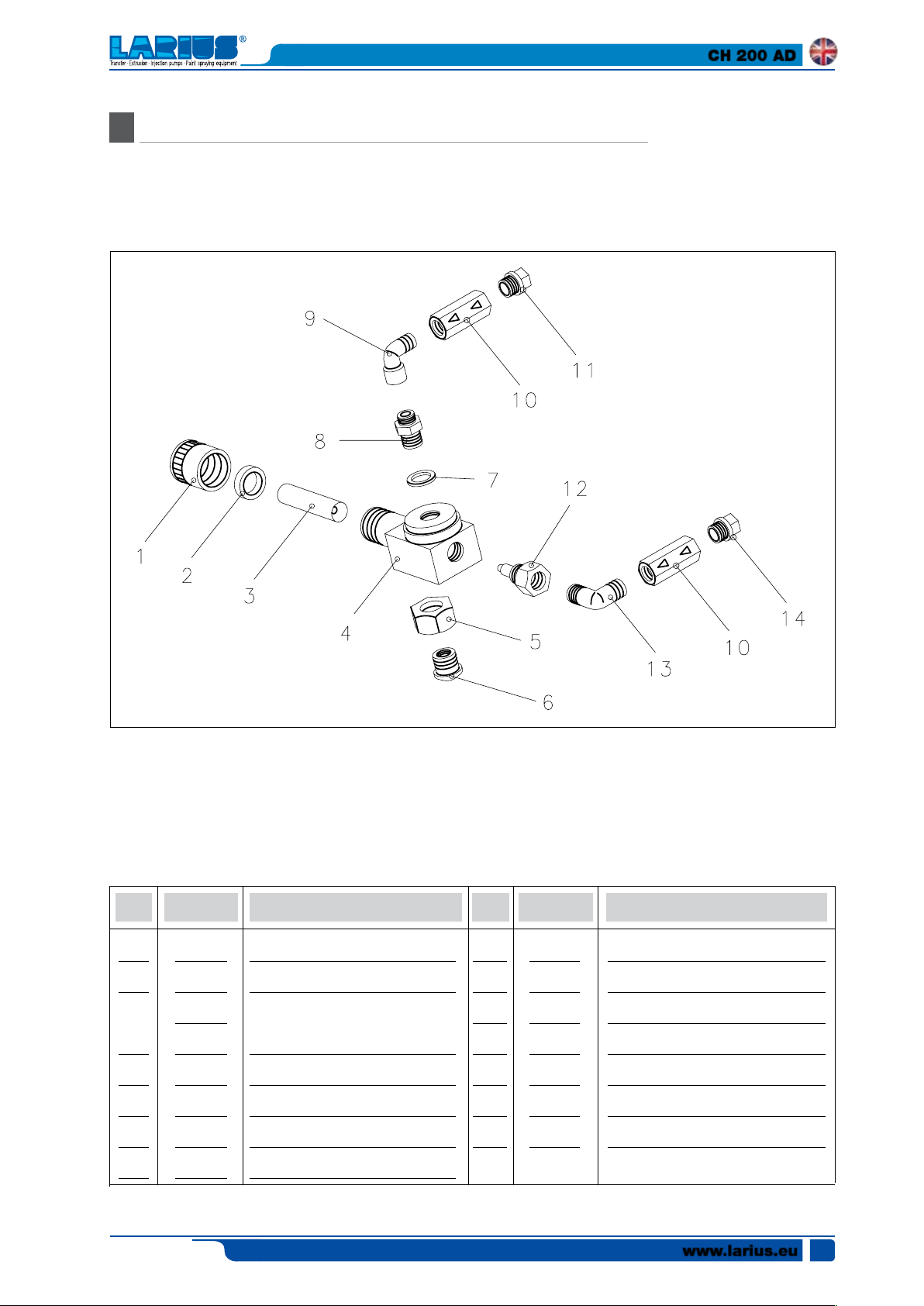
POWDER DELIVERY PUMP SPARE PARTS REF. 5505
Z
CH 200 AD
Pos. Pos.
1
2
3
.
4
5
6
7
Edit. 03 - 06/2019
Code Description Code Description
5297
5298
9977
9977
9976
5291
5290
32010
Ring nut
Ring
Venturi tube (Delrin)
Venturi tube (hard metal)
Body
Ring nut
Ogive
Washer
8
9
10
11
12
13
14
5294
5255
9902
5313
5288
3365
5312
Fitting
1/4" Elbow M-F
Unidirectional valve
Fitting for tube ø6
Fitting
1/4" Elbow M-M
Fitting for tube ø 8
www.larius.eu
41

CH 200 AD
ACCESSORIES
Y
Code 5243:
POWDER PASSAGE TUBE (PER METRE)
Code 5518:
BRUSH FOR CLEANING CH 200 SPRAY
GUN
Code 5010:
GROUNDING CABLE
Code 5573:
VENT TUBE (PER METRE)
www.larius.eu
42
Edit. 03 - 06/2019

PAINT SPRAYING EQUIPMENT
L’innovazione.
Quella vera.

Made in Italy 1969
LARIUS srl
Via Antonio Stoppani 21 - 23801 Calolziocorte (LC) ITALY
TEL. +39 0341 621152 - Fax +39 0341 621243 - larius@larius.com
www.larius.eu
 Loading...