

Larin TGL-500 Owner's Manual
1
OWNER’S MANUAL
MODEL # TGL-500
HITCH LIFT
For Customer Service Call or Fax
1 (800) 87-LARIN
2
SPECIFICATIONS……..
SPECIFICATIONS ARE SUBJECT TO CHANGE
WITHOUT NOTICE
Max Capacity:…………….500 lbs.
Motor Power:…………… 12 VDC
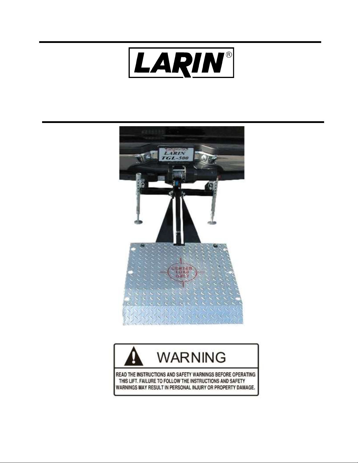
FIGURE 1 Contents of Carton A
Description Qty Part #
Hitch Adapter Plate……1 A C
Lifting Arm……………1 B
Guide Arms……………2 C B C
Pivot Tube……………..1 D
Platform Arms…………2 E
Outrigger Support …….1 F D
Outrigger Assemblies….2 G
E
E
F
G
Not Shown on this page (See Parts Diagram):
Hardware, CTN. #1
This box contains all the nuts, bolts and washers, and quick release pins and stabilizer clamp, outrigger assembly,
outriggers wrench and deck tie-downs.
Motorized cable module, CTN. #2
This box contains the motorized cable module, hex head cap screws, washers and nylon lock nuts required
to mount the module along with a hex key (allen wrench) for these bolts and cable set for connection to the battery.
Motor Controls, CTN. #3
This box contains the Pistol Grip Trigger, Limit Switch Assembly and screws, washers required to mount the Limit Switch
Assembly.
Deck Plate (On bottom of box)

3
ASSEMBLY INSTRUCTIONS
IMPORTANT SAFETY INFORMATION
It is the owner and/or operators responsibility to study and understand the safety and operating instructions before
operating this lift. Safety information shall be emphasized and understood prior to use. The lift shall be inspected per the
instruction manual prior to use. The lift shall be maintained in accordance with the product instructions. If the operator is
not fluent in English, the product warnings and instructions shall be read to and discussed with the operator in the
operator’s native language by the purchaser/owner or his designee, making sure that the operator comprehends their
content.
WARNING!
FAILURE TO FOLLOW THESE SAFETY WARNINGS MAY RESULT IN LOSS OF LOAD, DAMAGE TO LIFT, AND/OR
LIFT FAILURE RESULTING IN PERSONAL INJURY OR PROPERTY DAMAGE.
Study, understand and follow all instructions and warnings before operating.
Visual inspection shall be made before each use by checking for damage, wear, abnormal conditions such as bent, worn, loose,
missing parts or kinked or frayed cable.
Cable inspection shall be made in accordance with the instruction manual.
Inspect lift immediately if it is suspected to have been subject to abnormal load or shock. It is recommended that this inspection is
being made by the manufacturer’s authorized repair facility prior to use.
Owners and/or operators should be aware that repair of this equipment requires specialized knowledge and facilities. It is
recommended that an annual inspection be made by the manufacturer’s authorized repair facility and that any defective parts, decals
or safety labels or signs be replaced with the manufacturer’s specified parts.
If you encounter any problems or difficulties, contact the manufacturer’s toll free at 1-800-87-LARIN to reach customer service.
WARNING!
. USE HOLD DOWN STRAPS TO SECURE THE LOAD TO THE DECK PLATE WHEN NECESSARY.
. CENTER THE LOAD ON THE LIFT PLATFORM.
. DO NOT EXCEED THE RATED CAPACITY.
. USE THE OUTRIGGER ARMS WHEN RAISING OR LOWERING THE LOAD.
. DO NOT MOVE THE VEHICLE WITH THE LOAD ON THE PLATFORM.
. DO NOT ALLOW ANYONE TO BE ON OR BENEATH THE PLATFORM WHEN IT IS LOADED.
. NO ALTERATIONS SHALL BE MADE TO THIS PRODUCT.
. DO NOT USE THIS MOTORIZED CABLE MODULE FOR ANY OTHER PURPOSE.
. THE LIFT MAY BE PERTAINING TO POSSIBLE PINCH POINT HAZARDS,
ALWAYS BE OBSERVANT AND CAUTIOUS WHEN OPERATING THE LIFT.
. DO NOT ALLOW CHILDREN TO PLAY ON OR AROUND THE LIFT.
. DO NOT ALLOW CHILDREN TO OPERATE THE LIFT.
. DO NOT ALLOW THE CABLE TO KINK OR FRAY.
. REPLACE ANY DAMAGED CABLE BEFORE USE.
. INSPECT, CLEAN AND TIGHTEN ELECTRICAL CONNECTIONS PERIODICALLY.
. REMOVE THE POWER SUPPLY CORD AND THE PISTOL-GRIP CORD FROM THE MOTORIZED CABLE MODULE
BEFORE WORKING ON THE LIFT.
. NEVER ALLOW HANDS OR FINGERS IN THE AREA OF THE CABLE WHEN LIFT IS POWERED OR PISTOL-GRIP
TRIGGER IS ACTIVATED.
. THE LIFT IS NOT TO BE USED FOR LOADING OR UNLOADING PEOPLE.
. DO NOT ALLOW SLACK IN CABLE
. CHECK BATTERY CHARGE BEFORE USE.
4
ASSEMBLY INSTRUCTIONS
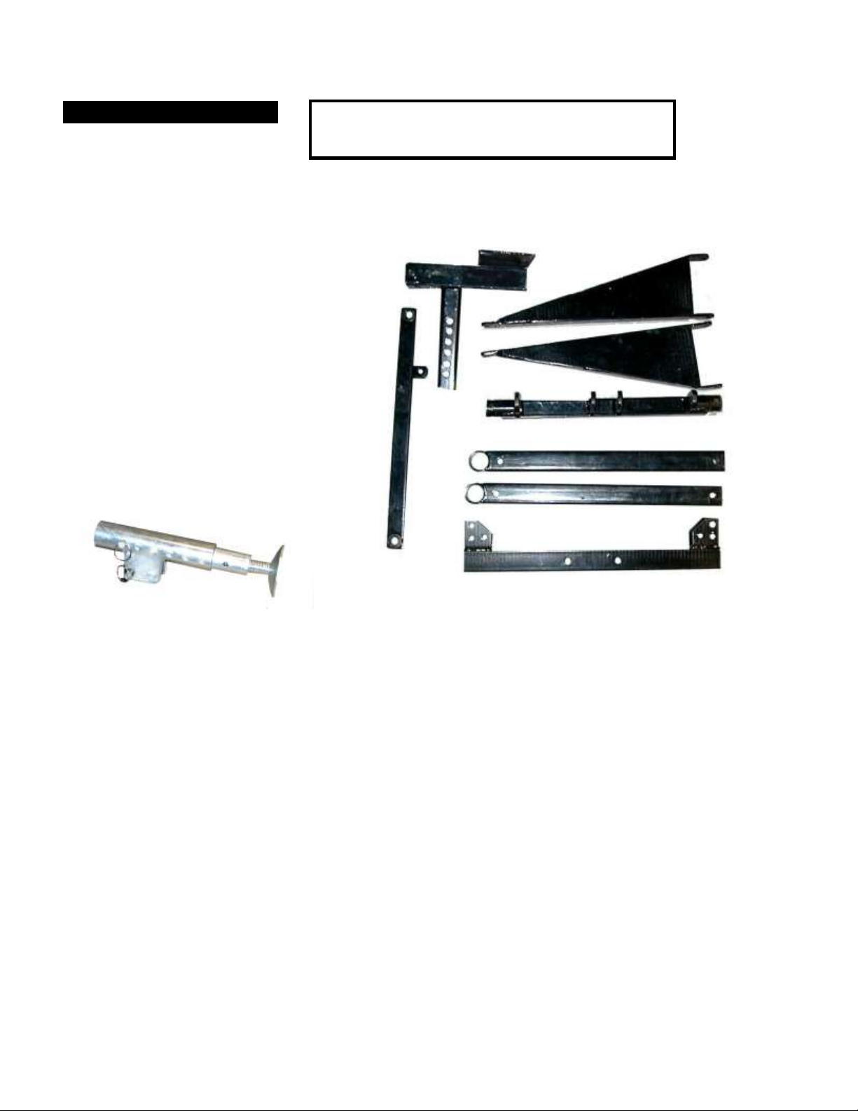
1 Attach the Outrigger Arm
Attach outrigger support (F) to the hitch adapter (A) using two M12 x 75 bolts (#14) A F
with M12 flat washers (#5) and M12 nylon lock nuts (#4).
2 Attach the Outriggers
Attach the two outrigger assemblies to the far outside lower holes in the outrigger
tube (F) as shown. Use a M12 x 75 bolt (#14) with a M12 washer (#5) and M12
nylon lock-nut (#4) on each bolt. Position the outrigger tubes as shown, then install a
quick release pin through the outrigger tube and outrigger assembly as shown.
After installing the pin, replace the securing clip in the pins. F
The assembly should now look like this…….
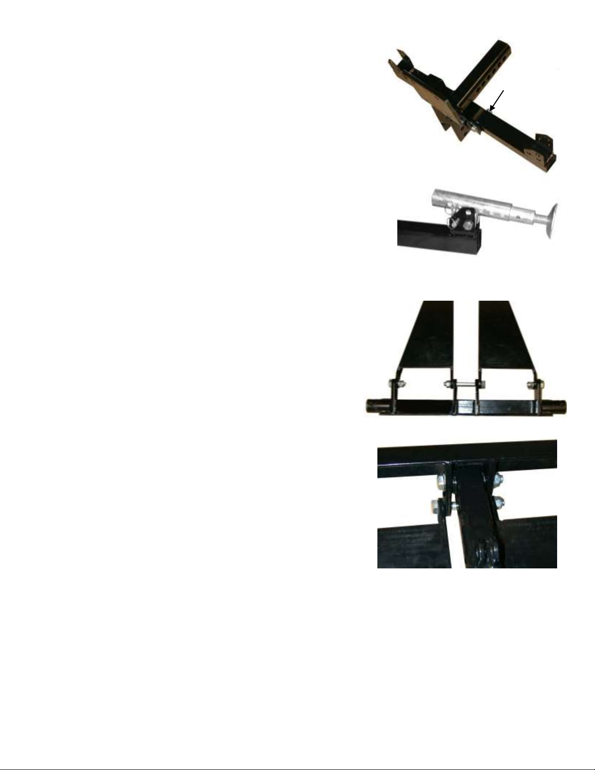
3 Attach the Guide Arms to the Pivot Tube
Attach the Guide Arms to the Pivot Tube. Start at the center holes (A) and
Use an M12 x 105 (#11) bolt with an M12 washer (#5) and an M12 nylon B A B
lock-nut (#4). Then Use M12 x 35 bolts (#6) with M12 washers (#5) and
M12 nylon lock-nuts (#4) on each of the Outside holes (B).
D
4 Attach the Lifting Arm to the Pivot Tube
Attach the Lifting Arm (B) to the Pivot Tube (D) using an M12 x 85 bolt (#7) and
An M12 washer (#5) and an M12 nylon lock-nut(#4). Notice that the tabs with the holes
In them face up and are closest to the Pivot Tube.
B
5 Attach the Lifting Arm and Guide Arms to the Hitch Adapter Plate
Attach the Lifting Arm (B) to the Hitch Adapter Plate (A) using an M12 x 85 bolt (#7) A
and an M12 washer (#5) and an M12 h all the parts. Secure it with an M12
washer (#5) and an M12 nut (#4). nylon lock-nut (#4). Now attach the two ends of the
Guide Arms (C) using an M12 x 105 bolt (#11) throug
 Loading...