

Larcan MXI802U User Manual

CONTENTS
1 THE MXi802 TRANSMITTER........................................................................................................................................3
2 MXi802U AMPLIFIER HEATSINK ASSEMBLY........................................................................................................4
3 MXi AMPLIFIER CONTROLLER.................................................................................................................................5
4 AMPLIFIER INSTALLATION AND STARTUP..........................................................................................................6
4.1 BEFORE APPLYING AC TO THE UNIT ............................................................................................................................6
4.2 APPLYING AC TO THE UNIT..........................................................................................................................................6
4.3 BEFORE TURNING THE AMPLIFIER ON .........................................................................................................................7
4.4 AMPLIFIER ON SEQUENCE............................................................................................................................................7
4.4.1 Turning ON the MXi Transmitter.........................................................................................................................8
4.4.2 TYPICAL DATA read on the LCD.......................................................................................................................9
5 TEST AND TROUBLESHOOTING .............................................................................................................................10
5.1 BENCH TEST PROCEDURES .........................................................................................................................................10
5.1.1 Front-End Module, 21B1473, Bench Test Procedure........................................................................................10
5.1.2 IPA1, 21B1324, Bench Test Procedure..............................................................................................................10
5.1.3 Driver Pallet, 21B1639, Bench Test Procedure.................................................................................................11
5.1.4 PA Pallet 11A2142G1 Bench Test Procedure....................................................................................................11
5.2 BASIC TROUBLESHOOTING TECHNIQUES ....................................................................................................................12
5.2.1 No RF Output.....................................................................................................................................................12
5.2.2 Output Reduced to 25%.....................................................................................................................................12
6 MAINTENANCE.............................................................................................................................................................13
6.1 DAILY.........................................................................................................................................................................13
6.2 MONTHLY...................................................................................................................................................................13
6.3 SEMI-ANNUALLY AND ANNUALLY .............................................................................................................................13
6.4 TRANSMITTER COOLING SYSTEM ...............................................................................................................................13
7 SERVICE..........................................................................................................................................................................14
7.1 REMOVING THE FAN ARRAY.......................................................................................................................................14
7.2 REPLACING THE ENTIRE FAN ARRAY .........................................................................................................................15
7.3 REPLACING A SINGLE FAN..........................................................................................................................................15
8 TEST EQUIPMENT SETUP..........................................................................................................................................16
9 SPECIFICATIONS .........................................................................................................................................................17
9.1 ELECTRICAL ...............................................................................................................................................................17
9.2 ENVIRONMENTAL.......................................................................................................................................................17
9.3 COOLING ....................................................................................................................................................................17
9.4 DIMENSIONS ...............................................................................................................................................................17
9.5 SHIPPING WEIGHT ......................................................................................................................................................17
FIGURES
FIGURE 1 MXI802 POWER SUPPLY (TOP), AND AMPLIFIERS.........................................................................................................3
FIGURE 2 MXI802 AMPLIFIER HEATSINK ASSEMBLY...................................................................................................................4
FIGURE 3 MXI CONTROLLER........................................................................................................................................................5
FIGURE 4 REAR PANEL SHOWING INTERLOCK CONNECTOR .........................................................................................................6
FIGURE 5 MAIN MENU..................................................................................................................................................................7
FIGURE 6 INTERLOCKS STATUS ....................................................................................................................................................7
FIGURE 7 TRANSMITTER ON ........................................................................................................................................................8
FIGURE 8 AGC ADJUSTMENT .......................................................................................................................................................8
PUB07-016 Rev 1 July 12, 2007 07-016-1 MXi802U Operations and Maintenance

FIGURE 9 BOTTOM VIEW OF MXI...............................................................................................................................................14
FIGURE 10 FAN ARRAY ..............................................................................................................................................................14
FIGURE 11 FAN ATTACHMENT TO MOUNTING PLATE.................................................................................................................15
FIGURE 12 TEST EQUIPMENT SETUP ...........................................................................................................................................16
PUB07-016 Rev 1 July 12, 2007 07-016-2 MXi802U Operations and Maintenance

1 THE MXi802 TRANSMITTER
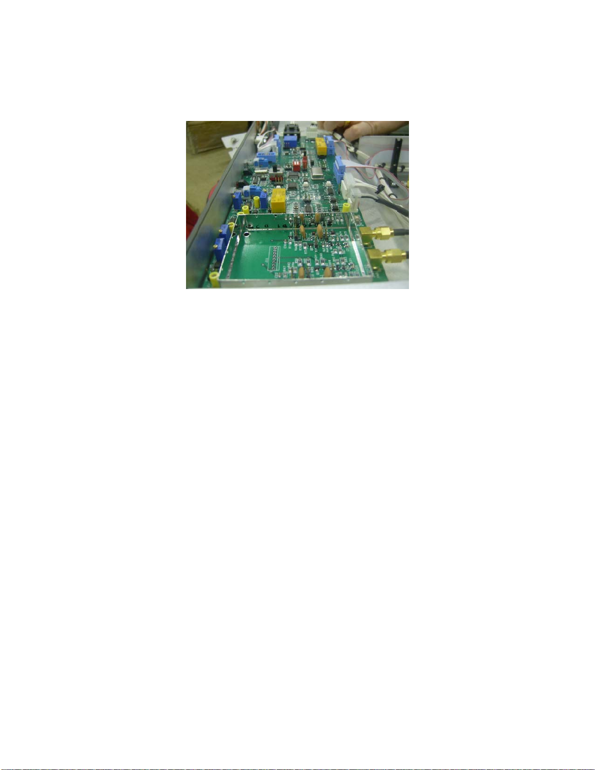
The MXi802 analog transmitter is usually comprised of a LARCAN IF Modulator, UHF Up-converter, a Power
supply chassis, and two Amplifier chassis. In some cases the modulator/up-converter combination is replaced by
a single unit Exciter or Channel Processor.
The RF section of the MXi802U consists of two identical amplifiers configured to operate in quadrature. Each
amplifier is capable of delivering power over 500 Watts sync peak. The output of these amplifiers are fed into a
two-way combiner assembly with built-in reject loads, and RF detectors which are used for protection and
metering purposes. Therefore, in this configuration, the MXi802 is capable of delivering RF power of up to 1kW
sync peak with exceptional performance and reliability.
The power supply chassis (top unit shown in Fig.1) contains the main controller board, LCD display, and two high
efficiency dual output (+12VDC and +32VDC) switching power supplies. The +12VDC power supply provides
power to the controllers, and the +32V supplies power to the amplifiers. Each power supply unit is rated at 2kW.
Figure 1 MXi802 Power Supply (top), and Amplifiers
PUB07-016 Rev 1 July 12, 2007 07-016-3 MXi802U Operations and Maintenance

2 MXi802U AMPLIFIER HEATSINK ASSEMBLY
Each amplifier assembly consists of a control board, a heatsink assembly that includes four cascaded broadband
amplifier stages, a 4-way splitter, a 4-way combiner, and a fuse block. The final amplifier stage (PA) comprises
four 200Wsp amplifiers configured in parallel. Error! Reference source not found.2 below shows the layout of
this assembly.
Figure 2 MXi802 Amplifier Heatsink Assembly
Also mounted on the heatsink located near the output side of the combiner is a thermal switch that protects the
amplifier from over temperature conditions. Cooling is achieved using multiple muffin fans located under the hood
between the heatsink and the controller. This fan-array assembly is accessible from the bottom of the amplifier
assembly, and can be serviced easily by removing 3 screws.
PUB07-016 Rev 1 July 12, 2007 07-016-4 MXi802U Operations and Maintenance
3 MXi AMPLIFIER CONTROLLER
The MXi amplifier control board (Assembly 31C1897) is a single-circuit assembly that provides all of the control
functions required for the MXi series amplifier on a single circuit board. This board can be configured for a number
of different amplifier types, power levels, transmission standards and options.
Figure 3 MXi Controller
The board implements status/telemetry for remote monitoring through a rear panel connector that will interface to
a typical remote control systems (such as Moseley or Gentner). An RS232 serial port is also provided to allow
communication with the main controller located inside the power supply chassis. The MXi control board has RF
detectors for forward and reflected power and all the circuitry to support AGC/VSWR/Cutback functions.
For complete documentation regarding the Amplifier Controller, see the publication MXi802U Amplifier Controller.
PUB07-016 Rev 1 July 12, 2007 07-016-5 MXi802U Operations and Maintenance
4 AMPLIFIER INSTALLATION AND STARTUP
The MXi802U Amplifier was fully tested at LARCAN before it was delivered. Under normal circumstances, the
transmitter can be fully operational with minimal setup when turned ON. However, a good practice is to take the
“start from scratch” approach, which means that one should take precautionary measures before the amplifier is
allowed to run at full rated power. These important steps will avoid any catastrophic failures at start-up. The
procedure described is essentially the same approach taken at the factory with a new and untested transmitter.
This also applies if there is a need to completely replace a major sub-assembly in the transmitter.
4.1 BEFORE APPLYING AC TO THE UNIT
Pay careful attention to items 1 to 3 before applying AC to the amplifier. These are initial steps that must be
observed and followed for proper and safe operation of the amplifier.
1. Termination
• Ensure that the amplifier is properly terminated with a suitable load. This can be into a dummy load or into
the transmitter output system. A 50 Ohm, 1kW load with at least –20dB return loss (1.2 VSWR) is
recommended. Preferably, directional couplers with known coupling levels at the frequency of interest
should be connected at the input and output of the band-pass filter. These points are very useful in
determining absolute power levels and losses, and also for use as an RF sample for monitoring purposes.
See Figure 12 for a typical transmitter test equipment setup.
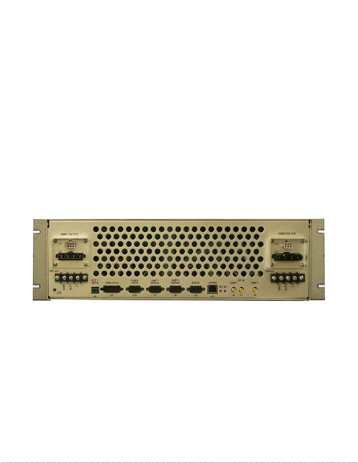
2. Interlocks
Interlocks must be connected to the amplifier to avoid damage to the equipment and to the output section. An
Interlock is provided at the EXT 1 INT’K connector located on the rear panel of the power supply chassis. If
this interlock is open, the B+ to the amplifiers will shut down, including the cooling fans.
Figure 4 Rear Panel Showing Interlock Connector
3. Power At Minimum
• Initially, the modulator’s IF output should be at minimum level. Adjust the `VIS IF LEV’ level control fully
counter-clockwise on the LARCAN modulator.
4.2 APPLYING AC TO THE UNIT
• Check that the AC MAINS going into TB1 and TB2 (across L1 and L2/N) ranges from 190-264VAC. If this
is so, proceed to applying power, otherwise, investigate the source of the problem.
• Usually, once the AC is applied to TB1 and TB2, the Control Power Supply turns ON and applies +12V to
the MXi Main controller in the power supply chassis, as well as in the controller in each amplifier.
• The Power-Up screen will be displayed on the LCD, followed immediately by the MXi Main Menu.
PUB07-016 Rev 1 July 12, 2007 07-016-6 MXi802U Operations and Maintenance
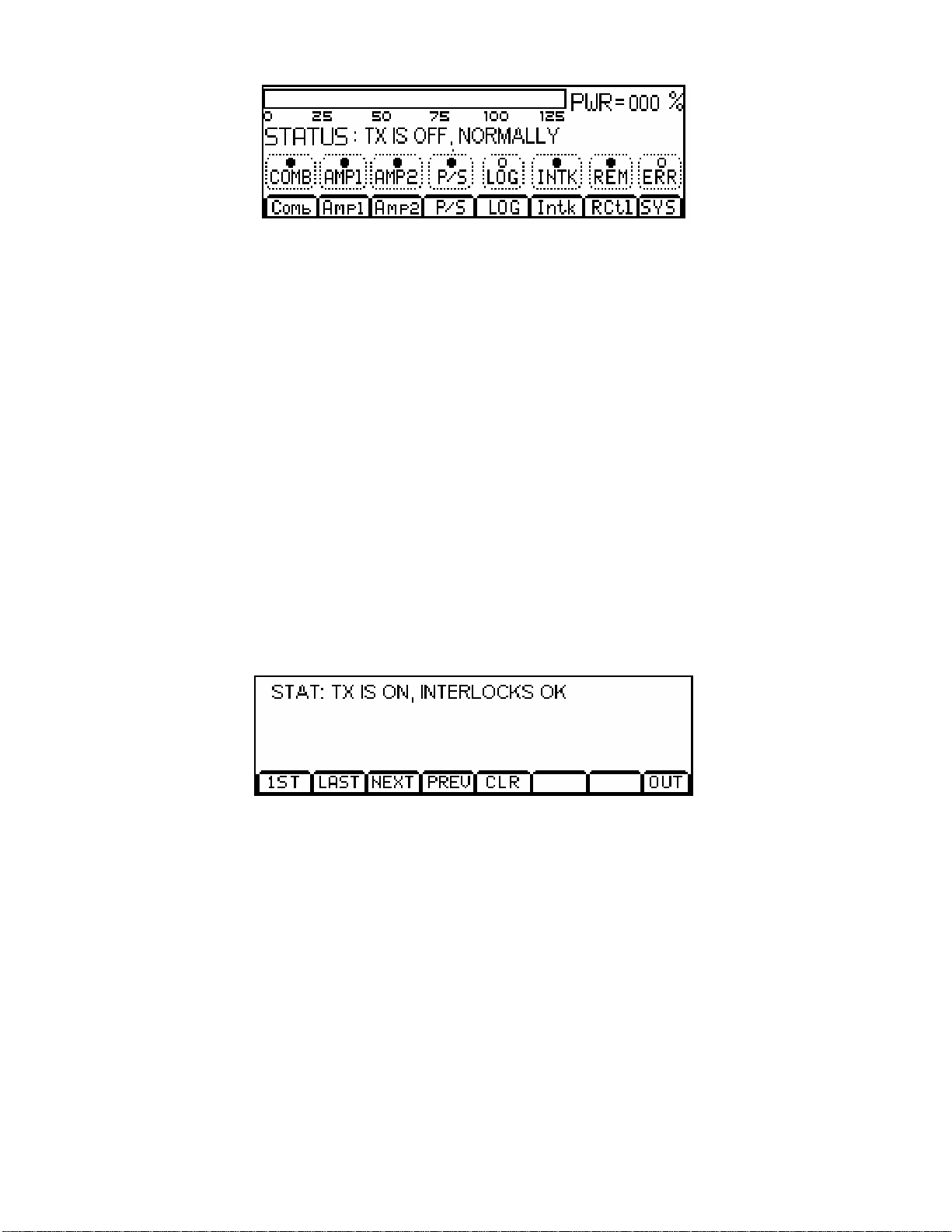
Figure 5 Main Menu
4.3 BEFORE TURNING THE AMPLIFIER ON
From the Main Menu, the status of the amplifier is displayed and shows if the amplifier is ready for operation.
Status legends, when lit, such as the INTK (INTERLOCK), usually signify OK conditions and that the transmitter is
ready to be switched ON.
Check that all of the following conditions are met:
1. Modulator and the up-converter, or Channel Processor are ready.
• Usually in the application of AC, the modulator goes through its warm-up sequence. When all of the red
LEDs are extinguished (not lit), it means that the modulator or up-converter is ready.
2. POWER METERING is at Zero.
• On the LCD (see Main Menu display in Error! Reference source not found.5), the PWR should be at
000% and the STATUS should be TX IS OFF, NORMALLY.
3. MXi MAIN CONTROLLER is ready.
• If there were prior faults, clear them by pushing the RESET button on the power supply chassis front
panel.
4. INTERLOCKS are closed or OK.
• Interlocks and Status are OK.
Figure 6 Interlocks Status
5. AGC control is DISABLED at this time.
• Remove the AGC jumper from the control board.
6. The Amplifier is in LOCAL mode.
• Push the REM button so that it is NOT lit.
7. The TX is OFF.
• Push the Front Panel ON/OFF button so that it is NOT pushed in.
4.4 AMPLIFIER ON SEQUENCE
Upon depressing the ON button, the fans start and at the same time the +32V power supplies are enabled, thus
applying B+ to both amplifies. Since the modulator/up-converter or Channel Processor are on hot standby (RF is
always applied), the amplifiers normally produces 100% output power immediately. For first time installations, it is
recommended that the level of the modulator be set to minimum initially and then increase in steps until 100%
power is attained. This is done so that catastrophic failure is avoided. Keep in mind that in a newly installed
PUB07-016 Rev 1 July 12, 2007 07-016-7 MXi802U Operations and Maintenance
transmitter that loose or bad connections in the output, as an example, is possible particularly when the output
system is not swept for proper matching or VSWR. Hence, as the power is increased, by observing the combined,
single amplifier, reflected, and reject power meterings one will be able to assess if everything is in proper order.
4.4.1 Turning ON the MXi Transmitter
1. Enable amplifier LOCAL operation by pressing the REM touch button such that the REM legend is NOT l it.
• Push the front panel ON button.
• The MXi Amplifier should now be ON.
Figure 7 Transmitter ON
2. Monitor both +32V power supply voltages and currents on the LCD. Check that the power supplies are
operating by pressing the P/S touch button. The voltage readings should be about 30V and the currents should be
about 11A under Static condition (no RF drive).
ALLOW THE AMPLIFIER SOME WARM-UP TIME!
Only after the transmitter has been ON for approximately 15 minutes should you perform the fine
adjustments. The amplifiers must be allowed to reach their operating temperature for stable operation. The
Power Amplifiers in the MXi transmitter are equipped with thermal compensation circuits, which reduce the
output power when the temperature rises. Therefore, the operating temperature must be reached before
adjusting the RF level to its proper level, i.e. 100%. The amplifiers are also equipped with Automatic Gain
Control, primarily designed to prevent the transmitter from overpower or overdrive condition.
3. Increase the RF output by slowly turning the Modulator/Exciter or Channel Processor output level control.
Stop at about 25% output power indicated on the LCD. At this level, the current should not be more than 35
Amps per amplifier.
4. If the current is not drastically higher, increase the power to 50%. Again, make note of the PS current
readings. The current should be less than 50 Amps per amplifier. Proceed to the next step if this condition is
met.
5. Increase the RF output to 100%. The current should be about 60A per amplifier with a black video signal.
Typically, with a 50% APL video signal, the current drawn is about 50A.
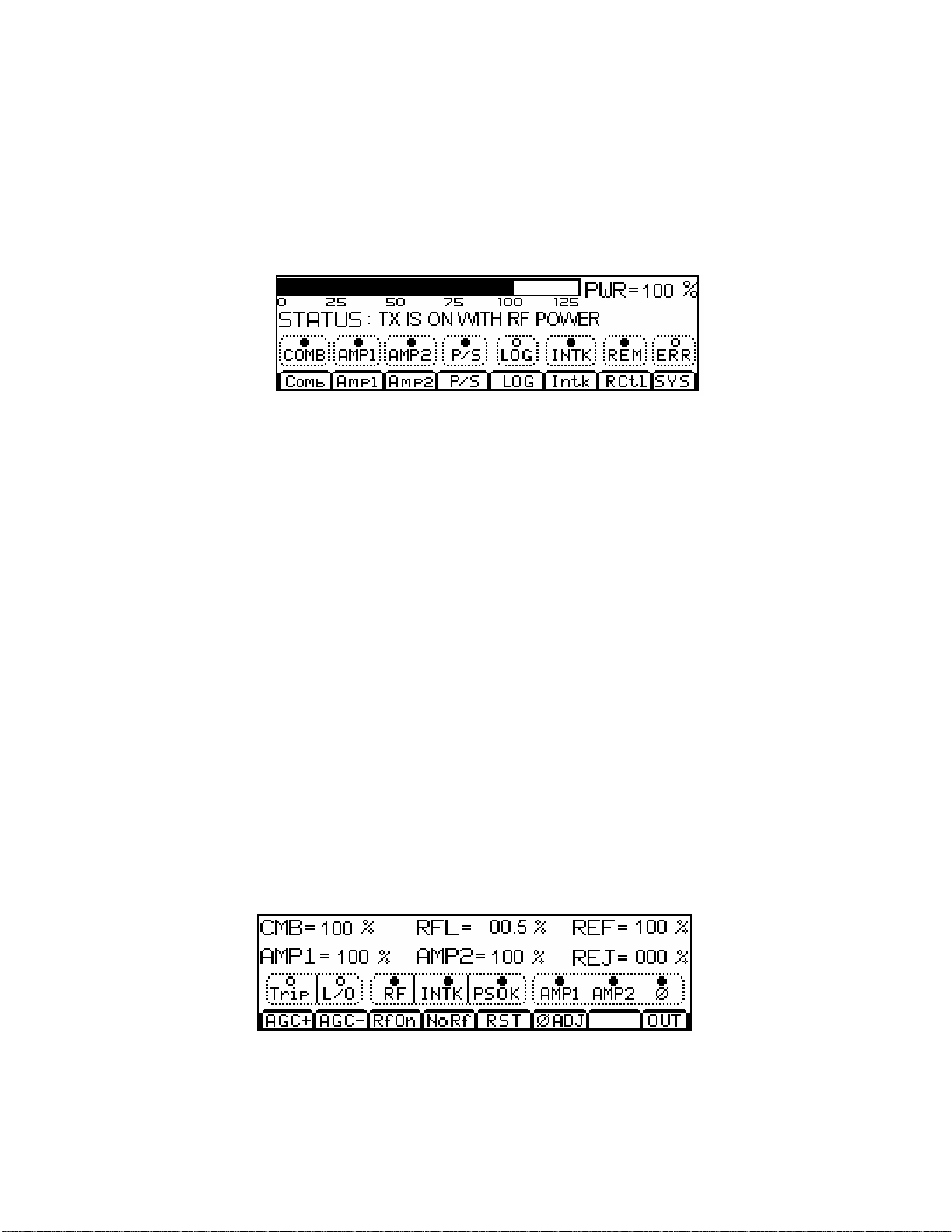
6. AGC SETTING: With the AGC still disabled, increase the output power to 110%, using the output level control
in the Exciter or Channel processor. Enable the AGC by inserting the AGC jumper, E16, on the control board.
Use the LOWER button on the LCD to set the power to 100%.
Figure 8 AGC Adjustment
7. With the amplifiers fully functional and adjusted to its final setting, record keeping becomes very important.
Record the current, voltage, power, etc. This data can be used as a very valuable troubleshooting tool later.
Below is typical test data pertaining to the MXi amplifier at 100% output power.
PUB07-016 Rev 1 July 12, 2007 07-016-8 MXi802U Operations and Maintenance

4.4.2 TYPICAL DATA read on the LCD
Combined
COMB 100% RFL 0.5%
AMP1 100% AMP2 100%
Amplifier
FWD 100% RFL 00.2%
AGC 1.0V CUTB 0.0V
Power Supply
PS1 VOLTS 30.0V PS2 VOLTS 30.0V
PS1 CURR 58.0A PS2 CURR 58.0A
PUB07-016 Rev 1 July 12, 2007 07-016-9 MXi802U Operations and Maintenance

5 TEST AND TROUBLESHOOTING
5.1 BENCH TEST PROCEDURES
The following procedures are test instructions for the amplifier modules comprising the MXi amplifier.
5.1.1 Front-End Module, 21B1473, Bench Test Procedure
• Connect a +32V power supply to E1.
• Apply a 0dBm (1mW) RF input to the amplifier.
• Turn RV2 fully clockwise. The front-end should have a gain of 9dB. Adjusting R25 from one extreme to
the other should vary the gain by 4dB.
• RF Mute Check: Connect a variable supply to J3-2. Gradually increase the voltage until the gain drops by
30dB or more. The applied voltage should be approximately 2.5 volts.
• Reflected Power Cutback Check: Connect the variable supply to J4-9. Increase the voltage gradually until
the gain drops by 30dB or more. The voltage should be approximately 4.0 Volts ±0.2V. This same voltage
should also be present at J3-14. J3-6 should be 4.0 volts.
• Overdrive Cutback Check: Connect the variable supply to J3-7. Increase the voltage until the gain drops
by 30dB or more. The voltage should be 7.0 volts ±0.5V. The voltage at J3-11 should be the same and
the voltage at J3-7 should be 4.0 volts.
• Set an adjustable power supply to 2.0 volts. Connect this voltage to J4-1, J4-3 and J4-5 simultaneously.
J2-6 and J3-5 should be high. Disconnecting any one or more of J4-1, 3 or 5 should cause both J2-6 and
J3-5 to go low (0V).
5.1.2 IPA1, 21B1324, Bench Test Procedure
This amplifier must be mounted on a properly sized heatsink for testing.
• Connect a suitable load to the output of the Front-End module.
• On the unit under test (IPA), set RV200 fully clockwise and set RV110 fully counter-clockwise.
• Set variable power supply to 32.0 volts and set its current limit to 1 ampere.
• Apply the +32V to the feed-through capacitor of the pre-amp shield box.
• Adjust RV3 to achieve 6.5 ±0.2 volts at the junction of R5 and RV100.
• Adjust RV200 to achieve total current draw of 500 ±20 mA.
• Check that the junction of R100 and CR100 measures between 3.5 and 5.5 volts.
• Adjust RV110 to raise total current draw to 1000 ±50 mA.
• Check that the junction of R110 and CR110 measures between 3.5 and 5.5 volts.
• Increase the power supply current limiting to 2.2 Amps.
• Increase RV3 clockwise slowly and check that the maximum current limits itself at 1.6 ±0.1 Amp but do
not allow current to go above 2 amps while performing this test.
• Reset RV3 to achieve 6.5 ±0.2 volts measured at the junction of R5 and RV100.
• Check balance of the two transistors with a voltmeter connected between the hot sides of C105 and
C115; the difference in voltage should be less than 3mV.
• Apply RF drive (max. +18 from a pre-amp) and adjust C101, C103, C111, and C113 for minimum
frequency response ripple and flat response. Gain should be a minimum of 15dB with maximum variation
less than 0.5dB over the frequency range 470MHz through 860MHz (Note: output will then be about
+33dBm or 2 Watts for an input of +18dBm, so make sure you properly protect your test equipment).
PUB07-016 Rev 1 July 12, 2007 07-016-10 MXi802U Operations and Maintenance

• If roll off at the higher frequencies prevents meeting this gain-bandwidth specification, it may be
necessary to replace either C103 or C113 or both with a higher value; use variable capacitor made by
Johanson, part # 16E2320-2, which is 2.5 to 10pF.
5.1.3 Driver Pallet, 21B1639, Bench Test Procedure
• BIAS SETTING: Connect a 50-Ohm load to the output of the pallet.
• Before applying +32V to the module, adjust R12 fully clockwise. Limit the power supply current to 3.0A.
• Apply +32V to the B+ terminal. Monitor the current and adjust R12 counter clockwise (CCW) for a total
current of about 2.0A +
• Still monitoring the current, adjust R11 for the current to be at minimum, i.e. current dipping at 1.9A. This
procedure balances the current drawn by the devices, therefore, R11 should not be adjusted again unless
one or both transistors are replaced. Any bias adjustment required from here on should be done using the
overall bias adjustment, R12.
• Readjust R12 to 2.0A. This setting is an initial bias setting and may vary depending on the pallet’s
application. On analog transmitters, this adjustment is used to optimized the inter-modulation products as
well as the system linearity.
• Proceed to the next step if a network analyzer or similar equipment is available.
0.1A.
• RF SWEEP
of 470MHz to 860MHz should be 14 to 16dB.
: Adjust C7 for best frequency response. With the bias set at 2.0A, the gain in the frequency range
5.1.4 PA Pallet 11A2142G1 Bench Test Procedure
• BIAS SETTING: Connect a 50-Ohm load to the output of the pallet.
• Before applying +32V to the module, adjust R11 fully counter-clockwise. Limit the power supply current to
3.0A.
• Apply +32V to the B+ terminal. Monitor the current and adjust R11 clockwise (CW) for a total current of
2.0A + or – 0.2A.
• Proceed to the next step if a network analyzer or similar equipment is available.
• RF SWEEP
between 15 to 16dB.
: Adjust C4 for best frequency response. The gain, in the range of 470MHz to 860MHz, should be
PUB07-016 Rev 1 July 12, 2007 07-016-11 MXi802U Operations and Maintenance

5.2 BASIC TROUBLESHOOTING TECHNIQUES
One of the best tools in troubleshooting is knowing what the nominal figures or typical values of the MXi amplifier
when it is at its normal performance. If a fault condition occurs, then you can compare the data taken previously
with the present conditions and come up with a reasonable conclusion about what is at faul t.
The following describes some fault conditions and possible solutions.
5.2.1 No RF Output
• Check for proper power supply voltage and current
• Check for the presence of video signal to the modulator
• Ensure the modulator IF carrier switches are ON.
• Check for potential connector problems causing either no drive to a module pallet (input connector) or VSWR
(output connector) problems.
• Check the fuses on the driver stages.
5.2.2 Output Reduced to 25%
If the output is approximately 25%, a possible cause is a total loss of power from one of the amplifiers. The
Mxi802 transmitter utilizes a 3dB combiner to combine the power of the two RF amplifiers. If one amplifier
produces no output, half of the output of the operating amplifier goes to the output and the other half goes into the
reject loads. Similarly, most of the stages in the amplifier have redundancy built in them so that if one fails the
output of that stage will be reduced to quarter power (25%). A measurement of the current drawn by the amplifier
will determine if this condition exists. The IPA usually draws 1A. If the current is 0.5, then this is the case.
Similarly, the Driver or PA pallet draws 2.0A with no drive condition. If it reads 1.0A, then this is the case, also.
PUB07-016 Rev 1 July 12, 2007 07-016-12 MXi802U Operations and Maintenance

6 MAINTENANCE
Equipment which is regularly and carefully maintained is far less likely to be subject to sudden failure than that
which is operated without regard to basic maintenance requirements. A detailed preventive maintenance program
should be established to ensure that the original efficiency and picture quality is maintained throughout the life of
the equipment. Given reasonable care and attention, the transmitter will provide efficient and reliable service for
many years.
Preventive maintenance techniques do not necessarily involve extensive dismantling of the various assemblies;
on the contrary, this practice is to be discouraged unless a valid reason exists for doing so. Preventive
maintenance is more directed at detailed physical inspection and the general observation of the equipment during
and after operation, to detect the presence of any abnormality, which, if not corrected, might result in operational
failure.
In preparing any maintenance program, the frequency and scope of the inspections must be determined and to a
great degree will be influenced by site location and the station's market parameters and consequently its hours of
operation, equipment configuration, and technical personnel deployment. For example, is the station on the air for
24 hours-a-day? Are there main/standby transmitters and are they attended or unattended?
In general, the following routines should form the basis of any maintenance program.
6.1 DAILY
At an attended site, the operator is afforded the opportunity to make frequent checks on the equipment and
thereby increase his/her familiarity with its operation. The transmitter log entries made during these checks would
include all meter readings, also any irregularity in performance or in picture quality, for later analysis. An
unattended site where equipment is operated by remote control and monitored by telemetry and a high quality offair receiver or demodulator can also be continuously checked for performance by studio technical personnel.
6.2 MONTHLY
In addition to the normal operational tests, thorough physical inspection of every piece of equipment should be
made, with all power turned off. All surfaces should be dusted off or wiped down, terminal boards checked for
loose connections, and all components examined for any evidence of overheating. Air filter media should be
inspected and replaced if necessary. High-pressure air, not over 20psi, can be used with discretion to dislodge
dust from inaccessible places.
6.3 SEMI-ANNUALLY AND ANNUALLY
Check all external RF connections for tightness, looking specifically for any discoloration, which might indicate a
loose inner connector, flange or sleeve coupling. Test the passive RF system with a transmission test set or
network analyzer, if one is available, to identify any potential problems with the antenna or line. Inspect and clean
contacts on all switches and contactors; carefully redress contact surfaces if pitted.
Check the operation of all interlocks including patch panel, dummy load, air and thermal switches and emergency
interlocks (if applicable).
6.4 TRANSMITTER COOLING SYSTEM
All cooling fans in the transmitter are fitted with sealed bearings requiring no lubrication during the lifetime of the
motor. Access to the fan assembly is via the bottom of the transmitter.
PUB07-016 Rev 1 July 12, 2007 07-016-13 MXi802U Operations and Maintenance

7 SERVICE
The MXi contains few user-serviceable parts; the modular surface-mount design makes module replacement
and/or factory repair the most efficient repair method.
The service most likely to be performed by users is the replacement of the fan array.
7.1 REMOVING THE FAN ARRAY
The MXi fan array consists of four 4” muffin-type fans which are attached to the mounting plate. The mounting
plate is secured to the bottom of the MXi chassis with five Phillips head screws.
Figure 9 Bottom View of MXi
1. Turn the MXi OFF.
2. Disconnect the AC power from the MXi.
3. Slide the MXi partially out from the mounting rack. Important: Ensure that the weight of the MXi is fully
supported.
4. With a Phillips screwdriver, remove the five mounting screws on the underside of the MXi. When
removing the last screw, be sure to hold the mounting plate in place.
5. Remove the mounting plate. The fan array is attached to the mounting plate and comes out with the plate.
Figure 10 Fan Array
PUB07-016 Rev 1 July 12, 2007 07-016-14 MXi802U Operations and Maintenance

7.2 REPLACING THE ENTIRE FAN ARRAY
In the event of a fan failure, LARCAN recommends replacing the entire array, as all fans have a similar lifespan.
1. Remove the fan array as described in Section 7.1.
2. Slide the new fan array into the MXi. The power connection is aligned so that it connects when the
mounting plate is fully in place.
3. Insert and tighten the five mounting screws. Note: Screws only need to be snug; do not overtighten.
7.3 REPLACING A SINGLE FAN
1. Remove the fan array as described in Section 7.1.
2. Each of the four fans is attached to the mounting plate via two screw-and-nut assemblies. Remove the
screws and nuts and set aside.
Three-pin
wiring harness
connector
Screw-andnut
assemblies
Figure 11 Fan Attachment to Mounting Plate
3. Disconnect the three-pin wiring harness connection by gently sliding it back with a fingernail or small
plastic tool.
4. If necessary, carefully cut and remove the zip tie holding the wires to the fan frame.
5. Remove the defective fan and replace with a known good fan of exactly the same dimensions and
specifications.
6. Re-connect the three-pin wiring harness connection.
7. Re-fasten the two screw-and-nut assemblies holding the fan to the mounting plate.
8. If necessary, replace the zip tie holding the wires to the fan frame.
9. Replace fan array into MXi as described in Section 7.1.
PUB07-016 Rev 1 July 12, 2007 07-016-15 MXi802U Operations and Maintenance

8 TEST EQUIPMENT SETUP
MXi802U OPERATIONS AND MAINTENANCE
Figure 12 Test Equipment Setup
PUB07-016 Rev 1 July 12, 2007 07-016-16 MXi802U Oper ations and Maintenance

MXi802U OPERATIONS AND MAINTENANCE
9 SPECIFICATIONS
Specifications are subject to change without notice.
9.1 ELECTRICAL
AC Line Input ...................................................................................................................190 to 264VAC, 50 to 60Hz
Power Consumption, black picture + 10% aural ...............................................................................4000VA (typical)
9.2 ENVIRONMENTAL
Ambient Temperature .....................................................................................................0°C to +45°C (0°F to 113°F)
Humidity .....................................................................................................................................................0% to 90%
Altitude ..............................................................................................................................................2286 m (7500 ft)
9.3 COOLING
Four 4” muffin fans per amplifier push air through the heatsinks and through the rear panel p erforations.
9.4 DIMENSIONS
The Amplifiers, Power Supply, IF Modulator, and Up-converter chassis are standard 19" rack wide units.
Height
Amplifiers and Power Supply......................................................................................................15.75" (9RU)
I.F. Modulator................................................................................................................................1.75” (1RU)
Up-converter.................................................................................................................................1.75” (1RU)
Total Height ..............................................................................................................................19.25” (10RU)
Depth is 31" to the back of the 2-way combiner.
9.5 SHIPPING WEIGHT
Weight
Amplifier (each) ……………………………….………...........................................Approximately 17kg (37lbs)
Power Suppl y ……………………………….………..............................................Approximately 18kg (40lbs)
2-Way Com biner ……………………………….……… ..........................................Approximately 3.6kg (8lbs)
Total Weight ……………………………….………..............................................Approximately 55kg (122lbs)
PUB07-016 Rev 1 July 12, 2007 07-016-17 MXi802U Operations and Maintenance

MXi802U AMPLIFIER CHASSIS
CONTENTS
1 MXi802U AMPLIFIER.....................................................................................................................................................1
FIGURES
FIGURE 1 FRONT VIEW OF MXI802U AMPLIFIER .........................................................................................................................1
FIGURE 2 REAR VIEW OF MXI802U AMPLIFIER...........................................................................................................................1
FIGURE 3 MXI FAN ARRAY ..........................................................................................................................................................2
FIGURE 4 MXI AMPLIFIER INTERIOR ............................................................................................................................................2
FIGURE 5 41D2168 MXI401/802 AMPLIFIER WIRING SCHEMATIC SHT1 REV 0 ...........................................................................3
PUB07-011 Rev 0 January 9, 2007 07-011-i MXi802U Amplifier Chassis

MXi802U AMPLIFIER CHASSIS
1 MXi802U AMPLIFIER
The MXi802U Amplifier Chassis Assembly 41D2101G4 consists of a standard 19" rack mountable 5.25" (3RU)
enclosure containing the amplifier heatsink assembly, a fan array assembly consisting of four DC cooling fans, a
controller board with built-in RF detectors, and a rear panel assembly with connectors for interfacing to external
equipment. Figure 1 is a front view of the MXi802U amplifier.
Figure 1 Front View of MXi802U Amplifier
Figure 2 Rear View of MXi802U Amplifier
The rear of the MXi802U AMPLIFIER has the following connectors (from left to right):
• RS232 SERIAL nine-pin connector
• REMOTE CONTROL 15-pin D-shell connector
• RF IN SMA connector
• INTERLOCK terminal board
• RF TP SMA connector – RF sample
• RF OUT N connector
• 12V 6-pin connector
• 28V 4-pin connector
The MXi802U is classified as a broadband amplifier, thus it is operational to cover the entire UHF television
spectrum ranging in frequencies from 470MHz to 860MHz.
Controlled DC power to the amplifier assembly comes from the high efficiency 2000W switching power supply via
a 32V four-pin connector. Regulated DC of 32V from the switching power supply is the B+ voltage to the amplifier
heatsink assembly. The second auxiliary output of the power supply is +12VDC, which is used for powering the
controller and the cooling fans.
The heatsink cooling fans are the +12VDC, 4-inch muffin model. Typically, they come ON at the same time B+ is
applied to the power amplifier. The voltage is supplied to the amplifier from the 12V six-pin connector on the rear
panel and it is connected to the controller PC board connector, J8. As built, the cooling fans push air from the
PUB07-011 Rev 0 January 9, 2007 07-011-1 MXi802U Amplifier Chassis

MXi802U AMPLIFIER CHASSIS
front panel through the heatsink and through the perforations in the rear panel. This assembly is located
underneath the MXi Controller board.
Figure 3 MXi Fan Array
A thermal switch is mounted on the heatsink where the operating temperature is sensed. If this temperature
increases beyond the trip point of the thermal switch, which is about 76°C, its contact opens and breaks the
interlocking circuit of the MXi amplifier. The interlock circuit ultimately controls the power supply to the power
amplifier and therefore shuts down and remains OFF until the heatsink cools do wn to abo ut 60°C.
Figure 4 MXi Amplifier Interior
A directional coupler is built into the 4-way combiner mounted at the rear of the heatsink and provides forward
and reflected RF signals to the controller. These RF samples are detected and processed on the MXi controller to
provide DC outputs corresponding to these signals. They are then used for AGC, VSWR supervision and this
information is also sent serially through the RS-232 connection to the main controller located inside the power
supply chassis.
The chassis is wired according to the functional diagram 41D2168 as shown in Figure 5.
PUB07-011 Rev 0 January 9, 2007 07-011-2 MXi802U Amplifier Chassis

MXi401/802U POWER AMPLIFIER HEATSINK ASSEMBLY
CONTENTS
1 POWER AMPLIFIER HEATSINK ASSEMBLY 40D2104G 1.....................................................................................1
2 FRONT END MODULE ASSEMBLY 21B1473G1........................................................................................................2
3 IPA MODULE 21B1951G1...............................................................................................................................................3
4 DRIVER MODULE 21B1639G1......................................................................................................................................5
5 PA PALLET ASSEMBLY 11A2142G1 ...........................................................................................................................6
6 FOUR-WAY SPLITTER 21B2425G1..............................................................................................................................7
7 FOUR-WAY COMBINER 21B2426G1...........................................................................................................................8
FIGURES
FIGURE 1 MXI SUB-ASSEMBLIES .................................................................................................................................................1
FIGURE 2 FRONT END MODULE....................................................................................................................................................2
FIGURE 3 IPA MODULE ................................................................................................................................................................3
FIGURE 4 DRIVER MODULE ..........................................................................................................................................................5
FIGURE 5 PA PALLET ASSEMBLY .................................................................................................................................................6
FIGURE 6 FOUR WAY SPLITTER....................................................................................................................................................7
FIGURE 7 FOUR WAY COMBINER .................................................................................................................................................8
FIGURE 8 MXI AMPLIFIER REAR PANEL.....................................................................................................................................11
FIGURE 9 21B1473 MXI FRONT END UHF DTV DRIVER ASSEMBLY SHT1 REV 5.1..................................................................12
FIGURE 10 11A1354 MXI FRONT END UHF DTV DRIVER SCHEMATIC SHT1 REV 2.1...............................................................13
FIGURE 11 21B1950A1 IPA FINAL ASSEMBLY SHT1 REV 2.......................................................................................................14
FIGURE 12 21B1950S1 IPA SCHEMATIC DIAGRAM SHT1 REV 0.1.............................................................................................15
FIGURE 13 21B1639S DRIVER PALLET SCHEMATIC SHT1 REV 5................................................................................................16
FIGURE 14 11A2142A1S PALLET CIRCUIT SCHEMATIC SHT1 REV 3..........................................................................................17
FIGURE 15 21B2425A1 4 WAY SPLITTER ASSEMBLY SHT1 REV 0.............................................................................................18
FIGURE 16 21B2425S1 4 WAY SPLITTER SCHEMATIC SHT1 REV 0 ............................................................................................19
FIGURE 17 21B2426A1 4 WAY COMBINER ASSEMBLY SHT1 REV 2...........................................................................................20
FIGURE 18 21B2426S1 4 WAY COMBINER SCHEMATIC SHT1 REV 2..........................................................................................21
PUB07-027 Rev 1 July 17, 2007 07-027-i MXi401/802U Power Amplifier Heatsink Assembly

MXi401/802U POWER AMPLIFIER HEATSINK ASSEMBLY
1 POWER AMPLIFIER HEATSINK ASSEMBLY 40D2104G1
The MXi Power Amplifier Heatsink Assembly 40D2104G1 consists of a fan-cooled heatsink and nine printed
circuit board sub-assemblies. The first module is a pre-amplifier, known as the Front-End Module, then the
Intermediate Power Amplifier, IPA. These first two stages are Class A amplifiers. Next is the Driver pallet, which is
biased so as to pre-correct for the non-linearity in the final amplifier stage. The next stage is the four way splitter
that splits the RF power so it can be fed to the PA pallets. The final amplifier stage is the PA pallets, which are
capable of delivering over 125W Analog power each. The last sub-assembly on the heatsink is the four way
combiner which combines the output power from the PA pallets. Also mounted on the heatsink is a thermal
switch, which protects the amplifiers from over-temperature conditions such as the absent of cooling or amplifier
over dissipation. This heatsink assembly is mounted in the Amplifier Chassis Assembly 41D2101G1. Descriptions
of each stage are detailed in the following pages.
Figure 1 MXi Sub-Assemblies
The above picture illustrates the arrangement of the sub-assemblies on the amplifier heatsink assembly. From
right to left are the Front-End, IPA and Driver modules. Centered and towards the back are the Splitter, PA
modules and the Combiner. Strategically installed on the heatsink, is a thermal switch which protects the amplifier
from over temperature conditions.
Cooling for the heatsink is provided by a fan array assembly consisting of four 4-inch axial flow +12VDC muffin
fans. This array is situated near the front section of the MXi housing underneath the MXi Amplifier Controller PC
board. The fans blow air into the finned portion of the heatsink, which exhausts through the rear.
PUB07-027 Rev 1 July 17, 2007 07-027-1 MXi401/802U Power Amplifier Heatsink Assembly
 Loading...