


TSM20-378
MXi030U AMPLIFIER
TECHNICAL SERVICE MANUAL
LARCAN INC.
228 AMBASSADOR DRIVE
MISSISSAUGA, ONTARIO
CANADA L5T 2J2
PHONE: (905) 564-9222
FAX: (905) 564-9244
EMAIL: techservices@larcan.com
PUBLICATION TSM20-378 Rev 0
July 18, 2007

MXi030U TECHNICAL SERVICE MANUAL
TSM20-378 MXi030U TECHNICAL SERVICE MANUAL
CONTENTS
1 INTRODUCTION .............................................................................................................................................................1
2 SAFETY NOTICES...........................................................................................................................................................2
2.1 BERYLLIUM OXIDE WARNING ......................................................................................................................................2
2.2 OTHER TOXIC MATERIALS ...........................................................................................................................................2
2.3 DANGEROUS VOLTAGES...............................................................................................................................................2
2.3.1 Switch to Safety....................................................................................................................................................3
3 LARCAN PARTS, ASSEMBLIES, ASSEMBLY DRAWINGS AND SCHEM ATIC NUMBERS............................5
3.1 VENDOR STANDARD PART NUMBERS...........................................................................................................................5
3.2 LARCAN NUMBERS FOR PARTS, ASSEMBLIES AND DOCUMENTATION .......................................................................5
3.3 LEADED RESISTORS......................................................................................................................................................6
3.4 SURFACE MOUNT RESISTORS 1/4W AND LESS .............................................................................................................6
3.5 SURFACE MOUNT CAPACITORS ....................................................................................................................................7
3.6 PARTS LISTS .................................................................................................................................................................7
3.6.1 Production Changes.............................................................................................................................................7
4 GLOSSARY.......................................................................................................................................................................9
PUB07-03 MXi HALF PALLET OPERATIONS AND MAINTENANCE
1 MXi AMPLIFIER..............................................................................................................................................................1
2 MXi CONTROLLER........................................................................................................................................................2
3 AMPLIFIER INSTALLATION AND STARTUP..........................................................................................................4
3.1 BEFORE APPLYING AC TO THE UNIT ............................................................................................................................4
3.2 APPLYING AC TO THE UNIT..........................................................................................................................................4
3.3 BEFORE TURNING THE AMPLIFIER ON .........................................................................................................................5
3.4 AMPLIFIER ON SEQUENCE............................................................................................................................................6
3.4.1 Turning ON MXi Amplifier..................................................................................................................................6
4 TEST AND TROUBLESHOOTING ...............................................................................................................................7
4.1 BENCH TEST PROCEDURES ...........................................................................................................................................7
4.1.1 Front-End Module Bench Test Procedure...........................................................................................................7
4.1.2 IPA1 Bench Test Procedure.................................................................................................................................7
4.1.3 PA Pallet 21B1751 Bench Test Procedure..........................................................................................................8
4.2 BASIC TROUBLESHOOTING TECHNIQUES ......................................................................................................................8
4.2.1 Amplifier Completely OFF...................................................................................................................................8
4.2.2 No RF Output.......................................................................................................................................................8
4.2.3 Output Reduced to 25%.......................................................................................................................................8
5 MAINTENANCE...............................................................................................................................................................9
5.1 DAILY...........................................................................................................................................................................9
5.2 MONTHLY.....................................................................................................................................................................9
5.3 SEMI-ANNUALLY AND ANNUALLY ...............................................................................................................................9
6 SERVICE..........................................................................................................................................................................10
6.1 REMOVING THE FAN ARRAY.......................................................................................................................................10
6.2 REPLACING THE ENTIRE FAN ARRAY ......................................................................................................................... 11
6.3 REPLACING A SINGLE FAN..........................................................................................................................................11
TSM20-378 Rev 0 July 18, 2007 20-378-ii MXi030U Technical Service Manual

MXi030U TECHNICAL SERVICE MANUAL
7 TEST EQUIPMENT SETUP..........................................................................................................................................12
8 SPECIFICATIONS .........................................................................................................................................................13
8.1 ELECTRICAL ...............................................................................................................................................................13
8.2 ENVIRONMENTAL.......................................................................................................................................................13
8.3 COOLING ....................................................................................................................................................................13
8.4 DIMENSIONS ...............................................................................................................................................................13
8.5 SHIPPING WEIGHT ......................................................................................................................................................13
PUB07-04 MXi HALF PALLET AMPLIFIER CHASSIS
1 MXi HALF PALLET AMPLIFIER................................................................................................................................. 1
PUB07-05 MXi HALF PALLET AMPLIFIER HEATSINK ASSEMBLY
1 HEATSINK ASSEMBLY 40D2052G1.............................................................................................................................1
2 FRONT END MODULE ASSEMBLY 21B1473G1........................................................................................................2
3 IPA MODULE 21B1951G1...............................................................................................................................................3
4 PA PALLET ASSEMBLY 21B1751G1............................................................................................................................5
5 DIRECTIONAL COUPLER 10A2121G3 .......................................................................................................................6
PUB05-67 MXi 500W POWER SUPPLY
1 MXi 500W POWER SUPPLY LAR500-32-P5337..........................................................................................................1
2 POWER SUPPLY MANUAL REPRINT........................................................................................................................3
PUB06-82 Rev2 MXi CONTROLLER BOARD
1 INTRODUCTION .............................................................................................................................................................1
2 GENERAL OPERATIONS..............................................................................................................................................3
2.1 CONNECTOR AND SIGNAL DEFINITIONS........................................................................................................................3
2.1.1 J1 BDM (Background Debug Mode) Connection................................................................................................3
2.1.2 J2 Remote RS232 Connection..............................................................................................................................3
2.1.3 J3 Front Panel LCD and Touchpad.....................................................................................................................3
2.1.4 J4 +28 Volt DC Power Supply.............................................................................................................................3
2.1.5 J5 +28 Volt DC Power Supply Sensing (External)..............................................................................................3
2.1.6 J6 Remote Controls..............................................................................................................................................3
2.1.7 J7 Transmitter Switch Interface...........................................................................................................................4
2.1.8 J8 Fan Interface...................................................................................................................................................4
2.1.9 J9 External Controls............................................................................................................................................ 4
2.1.10 J10 AGC Control.................................................................................................................................................4
2.1.11 J11 Aural Detector (Optional).............................................................................................................................4
2.1.12 J12 Forward RF Sample......................................................................................................................................4
2.1.13 J13 Reflected RF Sample.....................................................................................................................................4
2.1.14 J14 Front Panel LCD Power...............................................................................................................................4
TSM20-378 Rev 0 July 18, 2007 20-378-iii MXi030U Technical Service Manual

MXi030U TECHNICAL SERVICE MANUAL
2.2 JUMPER OPTIONS..........................................................................................................................................................4
2.2.1 BDM Slide Switch S2...........................................................................................................................................4
2.3 FRONT PANEL AND CONTROL INDICATORS...................................................................................................................7
2.3.1 Default/Normal E5= Ext E7=Out........................................................................................................................7
2.3.2 Manual Override E5= Int E7=Out......................................................................................................................7
2.3.3 Remote Override E5= Ext E7=In........................................................................................................................7
2.3.4 Manual and Remote Override E5= Int E7=In.....................................................................................................7
2.4 RF DETECTOR OPERATION ...........................................................................................................................................8
2.5 AGC, VSWR AND CUTBACK OPERATION ....................................................................................................................9
2.6 INTERLOCKS ...............................................................................................................................................................10
2.6.1 Hard Interlocks..................................................................................................................................................10
2.6.2 Soft Interlocks....................................................................................................................................................11
2.7 EXTERNAL SIGNALS AND REMOTE CONTROL.............................................................................................................11
2.7.1 External #1 Interlock .........................................................................................................................................11
2.7.2 Remote Controls (Individual).............................................................................................................................12
2.7.3 Remote Interface (Serial)...................................................................................................................................12
2.7.4 Transmitter Switching Interface.........................................................................................................................12
2.7.5 External DC Power Supply................................................................................................................................12
3 LCD GUI INTERFACE AND TOUCHPAD.................................................................................................................13
3.1 MAIN SCREEN AND TOUCHPAD OPERATIONS .............................................................................................................13
3.1.1 REM...................................................................................................................................................................14
3.1.2 AGC ...................................................................................................................................................................14
3.1.3 ERR....................................................................................................................................................................14
3.1.4 LOG ...................................................................................................................................................................14
3.1.5 AMP...................................................................................................................................................................15
3.1.6 P/S......................................................................................................................................................................15
3.1.7 INTK ..................................................................................................................................................................15
3.1.8 GEN ...................................................................................................................................................................15
3.2 AMPLIFIER SCREEN ....................................................................................................................................................15
3.2.1 TRIP...................................................................................................................................................................17
3.2.2 L/O.....................................................................................................................................................................17
3.2.3 RF ......................................................................................................................................................................17
3.2.4 INTK ..................................................................................................................................................................17
3.2.5 PSOK .................................................................................................................................................................17
3.2.6 FAN1 ..................................................................................................................................................................17
3.2.7 FAN2 ..................................................................................................................................................................18
3.3
POWER SUPPLY SCREEN ............................................................................................................................................. 19
3.3.1 OK STAT............................................................................................................................................................19
3.3.2 PS ON ................................................................................................................................................................19
3.3.3 INTK ..................................................................................................................................................................19
3.3.4 FAN....................................................................................................................................................................19
3.4 INTERLOCKS SCREEN.................................................................................................................................................. 19
3.4.1 TRIP...................................................................................................................................................................20
3.4.2 L/O.....................................................................................................................................................................21
3.4.3 TEMP.................................................................................................................................................................21
3.4.4 PSOK .................................................................................................................................................................21
3.4.5 VOR....................................................................................................................................................................21
3.4.6 CUTB.................................................................................................................................................................21
3.4.7 FANS ..................................................................................................................................................................21
3.5 REMOTE CONTROLS AND RS232 SERIAL SCREEN.......................................................................................................22
3.5.1 Remote ...............................................................................................................................................................23
3.5.2 NewFmt..............................................................................................................................................................23
3.5.3 ExtCmd ..............................................................................................................................................................23
3.5.4 SerCmd ..............................................................................................................................................................23
3.5.5 Error..................................................................................................................................................................24
3.5.6 Logs Screen........................................................................................................................................................24
TSM20-378 Rev 0 July 18, 2007 20-378-iv MXi030U Technical Service Manual

MXi030U TECHNICAL SERVICE MANUAL
3.6 GENERAL SCREEN ......................................................................................................................................................25
4 SETUP PROCEDURES..................................................................................................................................................27
4.1 RF DETECTOR ............................................................................................................................................................27
4.2 AGC AND CUTBACK PROTECTION..............................................................................................................................29
4.2.1 AGC Setup..........................................................................................................................................................29
4.2.2 Cutback Setup....................................................................................................................................................29
4.3 VSWR PROTECTION...................................................................................................................................................29
4.4 REMOTE CONTROL INTERFACE BAUD ........................................................................................................................30
4.5 POWER SUPPLY VOLTAGE AND CURRENT CALIBRATION............................................................................................31
5 REMOTE CONTROL CONNECTIONS MXi TRANSMITTER...............................................................................32
5.1 REMOTE CONTROLS....................................................................................................................................................32
5.1.1 RC_TX_On Remote Transmitter ON Control....................................................................................................33
5.1.2 RC_TX_Off Remote Transmitter OFF Control..................................................................................................33
5.1.3 RC_TX_VOR Remote Transmitter VOR Control...............................................................................................34
5.1.4 RC_RESET Remote RESET Control..................................................................................................................34
5.2 EXT1 SECONDARY EXTERNAL #1 INTERLOCK ...........................................................................................................34
5.2.1 Status Outputs....................................................................................................................................................35
5.3 TELEMETRY OUTPUTS ................................................................................................................................................35
6 CIRCUIT DESCRIPTIONS...........................................................................................................................................37
6.1 MC68HC908 MICROPROCESSOR................................................................................................................................37
6.2 POWER SUPPLY VOLTAGE AND CURRENT MONITORING ............................................................................................38
6.3 ON/OFF RELAY K1....................................................................................................................................................40
6.4 AGC, CUTBACK AND VSWR....................................................................................................................................40
6.5 SPI UART..................................................................................................................................................................41
6.6 SPI NVPOT ...............................................................................................................................................................42
6.7 RF DETECTOR ............................................................................................................................................................42
6.7.1 Circuit Description ............................................................................................................................................42
6.8 J12 CHANNEL – VISUAL FORWARD ............................................................................................................................42
6.9 J13 CHANNEL – REFLECTED .......................................................................................................................................43
6.10 J12 CHANNEL – AURAL FORWARD.............................................................................................................................44
7 ADDENDUMS.................................................................................................................................................................45
7.1 ADDENDUM 1– CDS51405 DISPLAY CONTROLLER....................................................................................................46
7.2 ADDENDUM 2–DUAL DIGITAL POTENTIOMETER WITH EEPROM .............................................................................49
7.3 ADDENDUM 3–SPI/MICROWIRE-COMPATIBLE UART AND +/-15KV ESD-PROTECTED RS-232 TRANSCEIVERS
INTERNAL CAPACITORS.....................................................................................................................................52
WITH
7.4 ADDENDUM 4–MC68HC908GTXX DATA SHEET .....................................................................................................55
7.5 ADDENDUM 5– CURRENT TRANSDUCER HXS 20-NP.................................................................................................62
TSM20-378 Rev 0 July 18, 2007 20-378-v MXi030U Technical Service Manual

MXi030U TECHNICAL SERVICE MANUAL
1 INTRODUCTION
This Technical Service Manual contains publications (PUBs) describing the technical details of the MXi030U
amplifier, as well as the overall operating instructions, including the bench test procedures of the amplifier stages
incorporated in this unit. It also covers the transmitter’s start-up operation, and troubleshooting, as well as basic
transmitter maintenance guidelines.
TSM20-378 Rev 0 July 18, 2007 20-378-1 MXi030U Technical Service Manual

MXi030U TECHNICAL SERVICE MANUAL
2
SAFETY NOTICES
This section provides general guidance and information for the operation, maintenance, and service personnel
who are familiar with the hazards of working with high-powered electronic circuits. This manual does not detail all
of the safety precautions which should be observed when servicing this or any other electronic equipment.
Service by inadequately trained or inexperienced personnel can result in personal injury or death and/or
damage to the equipment.
Important: All personnel concerned with the servicing of this equipment should be thoroughly familiar with
standard first aid procedures for the treatment of electrical burns and shock, including cardio-pulmonary
resuscitation (CPR).
Use the “buddy” system, with one person performing the actual service and a colleague observing. The observer
must be familiar with the work being performed and within sight and sound of the person doing the work. The
observer should not be engaged in any other work or be otherwise distracted; he must be available instantly in
case of accident.
Always have the observer with you when you work on the transmitter.
2.1
BERYLLIUM OXIDE WARNING
Internal thermal management in certain RF devices in this equipment is accomplished through the use of
Beryllium Oxide ceramic material. Do not break open any RF power transistors, or otherwise dismantle them.
Beryllium Oxide is a hard white ceramic used as insulation for heatsinking of RF power semiconductors. Beryllium
Oxide is a poison. In case of accidental breakage of devices, do not inhale the resulting beryllium dust and
avoid getting beryllium dust in your mouth. Do not let beryllium into your blood stream through cuts or
open wounds. Seek immediate medical attention if the dust enters your body in any manner. Avoid cuts by
wearing gloves while picking up the broken pieces. Be careful – do not inhale dust while replacing or emptying
vacuum cleaner filter bags and wash your hands thoroughly afterward. Wash your hands thoroughly after
replacing RF power devices. Dispose of defective RF power devices only through approved toxic waste facilities.
Wear gloves when picking up the pieces. Wash your hands thoroughly after replacing devices. Dispose of defective
devices only through approved toxic waste facilities.
When cleaning up after an accidental breakage, remember to wear a respirator mask to avoid inhaling the dust while
replacing or emptying vacuum cleaner filter bags and to wash your hands well after servicing the vacuum cleaner. If
possible, use a wet vacuum, in which the dust gets trapped in water.
2.2
OTHER TOXIC MATERIALS
The non-metallic coverings of some coaxial cables used in this equipment are flammable and can transmit fire
when ignited. Other wire coverings are not capable of supporting combustion but any non-metallic covering when
heated sufficiently can emit dense smoke and acid gases, which can be highly toxic and often corrosive.
Solvents and glues can emit toxic vapors and can be flammable. Read and understand the directions on the
containers and ensure that they are used only in well ventilated locations.
2.3
DANGEROUS VOLTAGES
This equipment has been designed to protect operating personnel from accidental contact with dangerous voltages,
by means of shields and covers. It is extremely important that any protective covering devices be kept in place at all
times.
While all practical safety precautions have been adopted to safeguard personnel from possible injury, both
supervisory and operating personnel are urged to ensure that the safety rules detailed below are followed as an
established routine at all times. The following four Rules are the standard safety guidelines for working with and
around transmitters.
TSM20-378 Rev 0 July 18, 2007 20-378-2 MXi030U Technical Service Manual

MXi030U TECHNICAL SERVICE MANUAL
Rule #1 KILL THE AC POWER BEFORE IT KILLS YOU
Under no circumstances should any person reach within the cabinets for the purpose of servicing or
adjusting the equipment without first disconnecting the AC power or without the immediate presence of
another person capable of rendering aid. The “buddy” system is encouraged for transmitter work.
Rule #2 DO NOT TAMPER WITH INTERLOCKS OR SAFETY SHIELDS
Under normal circumstances, no safety shield should be removed.
Rule #3 REMOVE PERSONAL JEWELRY WHEN WORKING ON THE EQUIPMENT
The mains AC power to this transmitter can deliver high currents capable of melting metallic tools or
personal jewelry, such as watch bands, bracelets, or rings. Accidental short circuits from such metallic
objects can cause an explosive shower of molten metal which can result in serious personal injury.
Rule #4 KNOW FIRST AID AND KEEP FIRST AID SUPPLIES AVAILABLE
Illustrated first aid instructions for the treatment of electrical shock and burns and CPR procedures should
be displayed in a prominent location adjacent to the equipment. In rendering first aid, the timeliness and
effectiveness of the treatment are vitally important to the recovery of the injured person.
Always have a colleague with you when you work on the transmitter and make sure both of you know first
aid, including cardio-pulmonary resuscitation (CPR). This is most important.
Without exception, all personnel should thoroughly familiarize themselves with the procedures involved. One
person, whose normal duties place him or her at the transmitter site often, should be given complete
responsibility and authority to ensure that first aid supplies are kept onsite and maintained. Prominently
display a list of emergency phone numbers. This list should include the numbers of the nearest police,
ambulance, hospital, doctor, fire department, paramedics, poison control center, public works (roads)
department, and the utility (power and phone) companies.
Do not try to work on the transmitter if you are tired or drowsy; you could make a fatal error in judgment.
2.3.1 Switch to Safety
Here are some safety suggestions, based partially on the knowledge of experts familiar with high-powered tubed
equipment, and partially on the procedures used at a typical utility company and at a company which makes and
tests high voltage devices. A few of these suggestions apply primarily to factory environments and require some
modification to be applied in transmitter settings.
Our thanks to the Varian Corporation for sharing its "Electrical Safety Training Program" notes. Our thanks also to
Ontario Hydro for its information booklets dealing with high voltage.
Have in place a comprehensive safety program, with defined procedures. Know First Aid and CPR.
Use the “buddy” system, with one person performing the actual service and a colleague observing. The observer
must be familiar with the work being performed and within sight and sound of the person doing the work. The
observer should not be engaged in any other work or be otherwise distracted; he must be available instantly in
case of accident. Always have the observer with you when you work on the transmitter.
Pay attention to emergency communications requirements. This could even include a voice channel on the STL
so that constant communication with the studio can be maintained. Headset-equipped phones connected on this
voice channel should be installed in locations near hazardous areas or everyone on site should carry fully
charged cell phones. When you are administering CPR, you might not be able to leave your patient for the length
of time it could take to call paramedics, especially if phone service is poor, or lines are down, and/or you are in a
rural area without emergency telephone service (e.g., 911 in North America).
Do not defeat the interlock switches on access doors unless it is absolutely necessary and you know exactly
what you are doing.
Keep the area neat and tidy, free of any interfering conductive material and free of any sharp objects. Remember
that reaction to a shock could cause you to strike nearby objects.
TSM20-378 Rev 0 July 18, 2007 20-378-3 MXi030U Technical Service Manual

MXi030U TECHNICAL SERVICE MANUAL
Avoid wearing loose clothing and personal jewelry such as rings, watches, and chains when working near
energized circuits. Make a habit of removing all jewelry and storing it in a safe place as soon as you enter the
transmitter building.
Before beginning work, shut off all AC to the transmitter power supplies. Tag and lockout the switches.
Your safety routine must ensure that the person placing the tag and locking the switch is the only person who
removes it and reactivates the switch. You might want to include the AC to the remote control as well, if there is
any possibility that a studio worker could unknowingly activate the transmitter while you are working on it. One
way of ensuring that the lockout "placer and remover" are the same person is to issue individual padlocks to each
person on the transmitter technical staff.
You might want to include your tower contractor's rigging crew in the list of people who are allowed to use tags
and padlocks. As an alternative, Dielectric™ makes a transmission line lockout switch that is intended for riggers
to turn off and lock out any RF before climbing over the antenna to replace light bulbs, etc.
Proper grounding is vital. Make ground inspection a part of your maintenance program; someone's life could
depend on it.
TSM20-378 Rev 0 July 18, 2007 20-378-4 MXi030U Technical Service Manual

MXi030U TECHNICAL SERVICE MANUAL
3
LARCAN PARTS, ASSEMBLIES, ASSEMBLY DRAWINGS AND SCHEMATIC NUMBERS
3.1
VENDOR STANDARD PART NUMBERS
Vendor or original manufacturer part numbers are indicated for most components.
3.2
LARCAN NUMBERS FOR PARTS, ASSEMBLIES AND DOCUMENTATION
An index of LARCAN specified number are used to define and specify the following:
• parts made by a manufacturer to LARCAN specification;
• an assembled unit or “group” such as a PC Board or completed cabinet;
• assembly drawings and schematics;
• standards.
Depending on the application, AutoCAD drawing or Microsoft Word document format is used.
Document numbers have the format YYZXXXXKn Rev m where:
YYZ Prefix denoting drawing size and Product type. Can be 10A, 11A, 20B, 21B, 30C, 31C, 40D, 41D, 50E, 51E
– describes drawing or document size, VHF or UHF application
XXXX Drawing Index number. Between 0000 to 9999.
K Refers to the type of drawing / document:
• “no suffix” for drawing of part (assembly or schematic)
• P = Part
• G = Group of parts
• A = Assembly drawing
• F = PC board fabrication films and
• S = Schematic
n Index number for drawing type. Part, group, assembly drawing or schematic next number and may be
one or more digits
Rev Revision (sometimes denoted as R or R–)
m Revision number and may be one digit or more. May contain a decimal (e.g., Revision 3.2)
Drawings may consist of one or more sheets. Generally multiple sheets are used if one sheet is not enough to
show all necessary information. Sometimes, especially with older drawings, multiple sheets are used to show
more than one part or assembly.
TSM20-378 Rev 0 July 18, 2007 20-378-5 MXi030U Technical Service Manual

MXi030U TECHNICAL SERVICE MANUAL
3.3 LEADED RESISTORS
Generic carbon composition resistors with leads are numbered as follows:
nnnx
3R
P
- or -
nnx
Power Rating Resistance Value * Tolerance
152 = 1/4W nn - first digits of K =10%
77 = 1/2W resistance (5, 10% tol.) J =5%
78 = 1W nnn - first digits of H =1%
79 = 2W resistance (1% tol.)
x - x10 multiplier
For values between 1Ω and 10Ω, a letter “R” will appear in the resistance value to indicate the decimal place.
For vendor leaded resistors a generic drawing describing basic specifications, but having many “parts”, will often
be used.
“3R152P5R6J” is 5.6Ω, 1/4W, ±5%
“3R152P470K” is 47Ω, 1/4W, ±10%
“3R152P1022H” is 10.2kΩ, 1/4W, ±1%
“3R152P102J” is 1kΩ, 1/4W, ±5%
3.4 SURFACE MOUNT RESISTORS 1/4W AND LESS
There is no specified recommended supplier of these parts. The Philips numbering system is employed with the
following parameters/designations (example follows):
9C
SIZE LxW POWER
nn=first 2 digits
x=multiplier
nnnx tolerance<5%
nnn=first 3 digits
nRnx or nnRnx or nRnnx
R inserted as decimal point
0000 - four zeros for jumper
RATING
0603=1.6x08mm 1 = 1/16W
0805=2x1.25mm 2 = 1/10W
1206=3.2x1.6mm 2 = 1/8W
(1% tol.)
3 =1/4W
(5% tol.)
A nnnx
RESISTANCE VALUE TOLERANCE TEMP COEF
nnx tolerance>=5%
x=multiplier
where required
D=0.5% C=50ppm/°C
F=1% K=100ppm/°C
J=5% L=200ppm/°C
M=300ppm/°C
The pairs of parameters enclosed in boxes are normally mutually selected; for example, a resistor having 1%
tolerance normally is selected as having a temperature coefficient of 100ppm/°C.
TSM20-378 Rev 0 July 18, 2007 20-378-6 MXi030U Technical Service Manual

MXi030U TECHNICAL SERVICE MANUAL
Example: 9C08052A1001FK
(Size 0805, Power Rating 1/10W, Resistance 1kohm, Tolerance 1%, Temperature
Coefficient 100ppm/°C)
3.5 SURFACE MOUNT CAPACITORS
There is no specifically recommended supplier of these parts. The part numbering system being used is based on
a Philips (now Yageo/Phycomp) numbering system with the following parameters/designations (example follows):
SIZE LxW DIELECTRIC
MATERIAL
0603=1.6x08mm CG = NPO nn =first 2 digits B=0.10pF 7=16VDC B=Ni/Sn
0805=2x1.25mm 2R = X7R
1206=3.2x1.6mm 2F = Y5V * x =multiplier as
9=x0.1
0=x1
1=x10
2=x100
3=x1000
4=x10000
5=x100000
* (infrequent use)
2E = Z5U *
shown below
8=x0.01
Nnx
CAPACITANCE
VALUE
(in Pico farads)
C=0.25pF 8=25VDC
D=0.50pF 9=50 VDC
F=1% 0=100VDC
G=2% B=200VDC
J=5% D=500VDC
K=10%
M=20%
TOLERANCE VOLTAGE
RATING
TERMINATION
A=Ag/Pd
C=Ni/Sn-Pb
e.g., 0805CG102J9B
SIZE =0805
DIELECTRIC MATERIAL =NPO
VALUE =1000pF
TOLERANCE =5%
VOLTAGE RATING =50V
TERMINATION =Ni/Sn
PACKAGING =Not Specified
MARKING =None
Note that “u” appears in most cases instead of the correct symbol “μ” whenever a “micro” is required. Electronic
parts list data, when imported by our PC publication program, allows us to substitute the correct “μ” when
checking and editing.
3.6
PARTS LISTS
Parts lists for all assemblies in the transmitter are provided on CD-ROM, in PDF format. The CD-ROM is packed
inside the transmitter cabinet for shipping.
Parts lists are generated in a hierarchical structure, beginning with major assemblies, then the subassemblies of
each major assembly, and so forth.
3.6.1
Production Changes
From time to time, it may become necessary to make changes in the equipment described in this manual. Such
changes are usually made either to provide improved performance or to accommodate component substitutions.
TSM20-378 Rev 0 July 18, 2007 20-378-7 MXi030U Technical Service Manual

MXi030U TECHNICAL SERVICE MANUAL
A revision letter or number may follow the model or group number marked on the nameplate, chassis, or circuit
board; or on the parts list (where it is an "R" followed by a dash and a number). Whenever a revision letter or
number appears, it should be quoted in any communication regarding the equipment.
TSM20-378 Rev 0 July 18, 2007 20-378-8 MXi030U Technical Service Manual

MXi030U TECHNICAL SERVICE MANUAL
4 GLOSSARY
The following glossary lists terms and abbreviations found in this and other LARCAN documentation.
REFERENCE DESIGNATOR ABBREVIATION DESCRIPTION
ADJ ADJUSTMENT/ADJUSTABLE
ALT ALTERNATE
AC ALTERNATING CURRENT
AWG AMERICAN WIRE GAUGE
AMP AMPLIFIER
AM AMPLITUDE MODULATION
ANA ANALOG
ADC ANALOG DIGITAL CONVERTER
E ANT ANTENNA
DS APHANUMERIC DISPLAY
ALU ARITHMETIC LOGIC UNIT
ARM ARMING
ASYNC ASYNCHRONOUS
AT ATT ATTENUATOR
LS AUDIBLE ALARM
AF AUDIO FREQUENCY
AUR AURAL
AUTO AUTOMATIC
AFC AUTOMATIC FREQUENCY CONTROL
AGC AUTOMATIC GAIN CONTROL
ALC AUTOMATIC LEVEL CONTROL
T AUTOTRANSFORMER
AVG AVERAGE
BNC BAYONET NEILL CONCELMAN CONNECTOR
BGA BALL GRID ARRAY
Z BALUN
BPF BANDPASS FILTER
BT BAT BATTERY
BZL BEZEL
BCD BINARY CODED DECIMAL
BCMOS BIPOLAR COMPLIMENTARY MOS
BLK BLOCK
B BLOWER
BRD BOARD
BTM BOTTOM
BKT BRACKET
W BUS BAR
BSHG BUSHING
LS BUZZER
CAB CABINET
W CBL CABLE
C CAP CAPACITOR
CATH CATHODE
CRT CATHODE RAY TUBE
CT CENTER TAP
CPU CENTRAL PROCESSING UNIT
CTR CENTRE
CER CERAMIC
CHAM CHAMFER
CHAN CHANNEL
CHAS CHASSIS
CB CB CIRCUIT BREAKER
HY CIRCULATOR
CLR CLEAR, CLEARANCE
M CLOCK
CW CLOCKWISE
COAX COAXIAL
L COIL
CMB COMBINE
TSM20-378 Rev 0 July 18, 2007 20-378-9 MXi030U Technical Service Manual

MXi030U TECHNICAL SERVICE MANUAL
CMOS COMPLIMENTARY METAL OXIDE
J CONN CONNECTOR
K CONTACTOR (MAGNETICALLY OPERATED)
S CONTACTOR
CW CONTINUOUS WAVE
CTRL/CTL CONTROL
CLG COOLING
CORR CORRECTION
CCW COUNTERCLOCKWISE
CPLR COUPLER
B/CPLR COUPLER BI-DIRECTIONAL
D/CPLR COUPLER DIRECTIONAL
COV COVER
Y XTAL CRYSTAL
CR CURRENT REGULATOR
DEFL DEFLECTOR
DL DELAY LINE
DEMUX DEMULTIPLEXER
DET DETECTOR
DIFF DIFFERENTIAL
DIG DIGITAL
DAC DIGITAL ANALOG CONVERTER
DPM DIGITAL PANEL METER
D DIODE
DIPL DIPLEXED
DDS DIRECT DIGITAL SYNTHESIS
DMA DIRECT MEMORY ACCESS
DC DIRECTIONAL COUPLER
P DISCONNECTING DEVICE (PLUG CONNECTOR)
J DISCONNECTING DEVICE (RECEPTACLE
DWG DRAWING
DIP DUAL IN LINE PACKAGE
D/L DUMMY LOAD
DRAM DYNAMIC ACCESS RANDOM MEMORY
ELEC ELECTRIC
E ELECTRICAL CONTACT
S ELECTRICAL SAFETY INTERLOCK
E ELECTRICAL SHIELD
ELECT ELECTROLYTIC (CONTEXT:CAPACITOR)
EMI ELECTROMAGNETIC INTERFERENCE
V ELECTRON TUBE
ELEK ELECTRONIC
LS ELECTRONIC BELL
M ELECTRONIC COUNTER
M ELECTRONIC TIMER
ECL EMITTER COUPLED LOGIC
ENCL ENCLOSURE
EQ EQ EQUALIZER
EXC EXCITER
EXH EXHAUST
EXT EXTERNAL
FFT FAST FOURIER TRANSFORM
FEM FEMALE
FPT FEMALE PIPE THREAD
E FERRITE BEAD RINGS
FET FIELD EFFECT TRANSISTOR
FPGA FIELD PROGRAMMABLE GATE ARRAY
FPLA FIELD PROGRAMMABLE LOGIC ARRAY
FL FILT FILTER
FWD FORWARD
FR FRAME
SEMICONDUCTOR
(MANUALLY, MECHANICALLY, THERMALLY
OPERATED)
CONNECTOR)
TSM20-378 Rev 0 July 18, 2007 20-378-10 MXi030U Technical Service Manual

MXi030U TECHNICAL SERVICE MANUAL
FREQ FREQUENCY
FDM FREQUENCY DIVISION MULTIPLEX
FM FREQUENCY MODULATION
FSK FREQUENCY SHIFT KEYING
FR FRONT
F FUSE
X FUSEHOLDER
G GENERATOR
GROM GROMMET
GND GROUND
GRP DEL GROUP DELAY
E HALL ELEMENT
HDL HANDLE
H HARDWARE
J HDR HEADER
HR HEATER
HR HEATING RESISTOR
HTSK HEATSINK
HCMOS HIGH DENSITY CMOS
HMOS HIGH PERFORMANCE MOS
HP HIGH POWER
HCT HIGH SPEED CMOS
HV HIGH VOLTAGE
HPS HIGHPASS FILTER
HORIZ HORIZONTAL
HSG HOUSING
HY HYBRID CIRCUIT NETWORK
ID IDENTIFICATION
E IGNITOR GAP
I INCIDENT
IOT INDUCTIVE OUTPUT TUBE
L IND INDUCTOR
L INDUCTOR
IN, I/P, INP INPUT
INSR, INST INSERT
INS INSIDE
M INSTRUMENT
E INSULATOR
U IC INTEGRATED CIRCUIT
U INTEGRATED CIRCUIT
I/C, INTCON INTERCONNECTION
INTRF INTERFERENCE
INTL INTERLOCK
IF INTERMEDIATE FREQUENCY
INT INTERNAL
ISOL ISOLATION
JFET JUNCTION FET
DS LAMP
LSI LARGE SCALE INTEGRATION
LDMOS LATTERALLY DIFFUSED MOS
LCC LEADED CHIP CARRIER
LCCC LEADLESS CERAMIC CHIP CARRIER
DS LED
LLCC LEADLESS CHIP CARRIER
LED LIGHT EMITTING DIODE
E LIGHTING ARRESTOR
LIN LINEAR
LCD LIQUID CRYSTAL DISPLAY
LOC LOCAL
LAN LOCAL AREA NETWORK
LO LOCAL OSCILLATOR
L/O LOCKOUT
LS LOUDSPEAKER
LNA LOW NOISE AMPLIFIER
TSM20-378 Rev 0 July 18, 2007 20-378-11 MXi030U Technical Service Manual

MXi030U TECHNICAL SERVICE MANUAL
LP LOW POWER
LV LOW VOLTAGE
LWR LOWER
FL LPS LOWPASS FILTER
E MAGNETIC CORE
Vcc MAIN POWER SUPPLY
M MALE
MPT MALE PIPI THREAD
MATL MATERIAL
MP MECHANICAL INTERLOCK
MP MECHANICAL PART
MP MEDIUM POWER
MOS METAL OXIDE SEMICONDUCTOR
MOSFET METAL OXIDE SEMICONDUCTOR FET
MOV METAL OXIDE VARISTOR
MTR METER
M METER
MK MICROPHONE
E MISCELLANUS ELECTRICAL PART
HY MXR MIXER
MOD MODEL
MOD MODULATION
MODEM MODULATOR/DEMODULATOR
MON MONITOR
B MOTOR
MTG MOUNTING
MAC MULTIPLEX ANALOG COMPONENT
MPX MULTIPLEXER
MUX MULTIPLEXER
NMPS N CHANNEL MOS
NEUT NEUTRAL
NONLIN NONLINEAR
NVM NON-VOLATILE MEMORY
NVRAM NON-VOLATILE RAM
OC OPEN COLLECTOR
U OPAMP OPERATIONAL AMPLIFIER
OPT OPTIONAL
OSC OSCILLATOR
G OSCILLATOR
M OSCILLOSCOPE
O/P, OUT OUTPUT
OCXO OVEN CONTROLLED CRYSTAL OSCILLATOR
O/I OVERCURRENT
O/L OVERLOAD
O/V OVERVOLTAGE
PMOS P CHANNEL MOS
PNL PANEL
PPNL PATCH PANEL
E PERMANENT MAGNET
PH PHASE
PLL PHASE LOCKED LOOP
PM PHASE MODULATION
Z PHASE SHIFTER
R POT POTENTIOMETER
RES VAR POTENTIOMETER
R POTENTIOMETER
PWR POWER
PFD POWER FLUX DENSITY
PS POWER SUPPLY
PS POWER SUPPLY
PREAMP PREAMPLIFIER
PFX PREFIX
PREF PREFIX
PRESS PRESSURE
TSM20-378 Rev 0 July 18, 2007 20-378-12 MXi030U Technical Service Manual

MXi030U TECHNICAL SERVICE MANUAL
P PRIMARY
PCA PRINTED CIRCUIT ASSEMBLY
PCBOARD PRINTED CIRCUIT BOARD
PCM PULSE CODE MODULATION
Q QUADRATURE
QAM QUADRATURE AMPLITUDE MODULATION
Y QUARTZ
RU RACK UNIT 1 3/4"
RF RADIO FREQUENCY
RFIC RADIO FREQUENCY INTEGRATED CIRCUIT
RFI RADIO FREQUENCY INTERFERENCE
RAM RANDOM ACCESS MEMORY
ROM READ ONLY MEMORY
RCVR RECEIVER
RX RECEIVING
J RCPTL RECEPTACLE
REF REFERENCE
RFL REFLECTED
REJ REJECT
RL REJECT LOAD
K RLY RELAY
K RELAY
REM REMOTE
R RES RESISTOR
R RESISTOR
Z RESONATOR (TUNED CAVITY)
RND ROUND
SMPL SAMPLE
S SECONDARY
Vdd SECONDARY POWER SUPPLY
SEL SELECT
SCLK SERIAL CLOCK
SIG SIGNAL
SNR SIGNAL TO NOISE RATIO
SCR SILICON CONTROLLED RECTIFIER
SOS SILICON ON SAPPHIRE
SPDT SINGLE POLE DOUBLE THROW
SPST SINGLE POLE SINGLE THROW
SOIC SMALL OUTLINE IC
SOT SMALL OUTLINE TRANSISTOR
SKT SOCKET
X SOCKET
SS SOLID STATE
SND SOUND
E SPARK GAP
SPL SPLITTER
STD STANDARD
STBY STANDBY
SPLY SUPPLY
SPRT SUPPORT
SAW SURFACE ACOUSTIC WAVE
SM SURFACE MOUNT
SMA SURFACE MOUNT ASSEMBLY
SMC SURFACE MOUNT COMPONENT
SMD SURFACE MOUNT DEVICE
SMT SURFACE MOUNT TECHNOLOGY
SW SW SWITCH
S SWITCH
SYNC SYNCHRONIZATION / SYNCHRONOUS /
SONET SYNCHRONOUS OPTICAL NETWORK
SYS SYSTEM
TANT TANTALUM
TECH TECHNICAL
TV TELEVISION
SYNCHRONISING
TSM20-378 Rev 0 July 18, 2007 20-378-13 MXi030U Technical Service Manual

MXi030U TECHNICAL SERVICE MANUAL
TEMP TEMPERATURE
TERM TERMINAL
E TERMINAL (INDIVIDUAL)
TERMBLK TERMINAL BLOCK
TB TERMINAL BLOCK
RT TERMISTOR
TC TERMOCOUPLE
TP TEST POINT
TP TEST POINT
M THERMOMETER
TSSOP THIN SHRINK SMALL OUTLINE PACKAGE
TSOP THIN SMALL OUTLINE PACKAGE
X XFMR TRANSFORMER
T TRANSFORMER
Q TRANSISTOR
TTL TRANSISTOR TRANSISTOR LOGIC
XLTR TRANSLATOR
XMTD TRANSMITTED
XMTR TRANSMITTER
TX TRANSMITTER
TX TRANSMITTER / TRANSMITTING
TRIM TRIMMING
UHF ULTRA HIGH FREQUENCY
UPS UNINTERRUPTABLE POWER SUPPLY
UUT UNIT UNDER TEST
UART UNIVERSAL ASYNCHRONOUS RECEIVER
UPR UPPER
VAR VARIABLE
VGA VARIABLE GAIN AMPLIFIER
D VARISTOR (ASYMETRICAL)
RV VARISTOR (SYMETRICAL)
VERT VERTICAL
VHF VERY HIGH FREQUENCY
VHV VERY HIGH VOLTAGE
VLSI VERY LARGE SCALE INTEGRATION
VIS VISION / VISUAL
VCXO VOLTAGE CONTROLLED CRYSTAL
VCO VOLTAGE CONTROLLED OSCILLATOR
VR VOLTAGE REGULATOR
VR VOLTAGE REGULATOR
W WAVEGUIDE
WLAN WIRELESS LOCAL AREA NETWORK
WRG WIRING
TRANSMITTER
OSCILLATOR
GENERAL
8VSB 8 LEVEL VSB
ATV ADVANCED TELEVISION SYSTEM (U.S.)
ATSC ADVANCED TELEVISION SYSTEMS
ACATS ADVISORY COMMITTEE ON ADVANCED
ASCII AMERICAN NATIONAL STANDARD CODE FOR
ANSI AMERICAN NATIONAL STANDARDS INSTITUTE
B&W BLACK AND WHITE
BBC BRITISH BRODCASTING CORPORATION
CATV CABLE TV
CRC COMMUNICATION RESEARCH CENTRE
COMP COMPOSITE
DTTV DIGITAL TERRESTRIAL TV
DVB DIGITAL VIDEO BRODCASTING
EIA ELECTRONICS INDUSTRIES ASSOCIATION
EDTV ENCHANCED DEFINITION TV
ENV ENVELOPE
COMMITTEE
TELEVISION SERVICE
INFORMATION INTERCHANGE
TSM20-378 Rev 0 July 18, 2007 20-378-14 MXi030U Technical Service Manual

MXi030U TECHNICAL SERVICE MANUAL
EBU EUROPEAN BRODCASTING UNION
DVB EUROPEAN DIGITAL TV
FCC FEDERAL COMMUNICATION COMMISSION
GPIB GENERAL PURPOSE INTERFACE BUS
GPS GEOGRAPHIC POSITIONING SYSTEM
HP HEWLETT PACKARD
HDTV HIGH DEFINITION TELEVISION
HD HIGH DENSITY
HTTP HYPERTEXT TRANSFER PROTOCOL
ICPM INCIDENTAL CARRIER PHASE MODULATION
INC INCORPORATED
ISO INDUSTRIAL STANDARDS ORGANIZATION
IEEE INSTITUTE OF ELECTRICAL AND ELECTRONIC
IEC INTERNATIONAL ELECTROTECHNICAL
ISO INTERNATIONAL ORGANIZATION FOR
OIRT INTERNATIONAL RADIO AND TELEVISION
CCIR INTERNATIONAL RADIO CONSULTATIVE
ITU INTERNATIONAL TELECOMMUNICATION UNION
MONO MONOPHONIC
MPEG MOTION PICTURE EXPERTS GROUP
NTSC NATIONAL TELEVISION STANDARD
OSHA OCCUPATIONAL SAFETY AND HEALH
PCS PERSONAL COMMUNICATION SERVICES
PAL PHASE ALTERNATING LINE TELEVISION
PDF PORTABLE DOCUMENT FORMAT
SAT SATELLITE
KuBand SATELLITE TO SATELLITE COMMUNICATION
SECAM SEQUENTIAL COULEUR A MEMORIE
SMPTE SOCIETY OF MOTION PICTURE AND
SDTV STANDARD DEFINITION TELEVISION
SCC STANDARDS COUNCIL OF CANADA
STEREO STEREOPHONIC
SUBCARR SUBCARRIER
WWW WORLD WIDE WEB
ENGINEERS
COMMISSION
STANDARDIZATION
ORGANISATION
COMMITTEE (NOW ITU-R)
COMMITTEE
ADMINISTRATION
STANDARD
FREQUENCY
TELEVISION ENGINEERS
ORGANIZATIONAL DEPARTMENTS, DOCUMENTS, FUNCTIONS
ASSY ASSEMBLY
BOM BILL OF MATERIAL
DA DEVIATION AUTHORIZATION
EA EACH
PL PARTS LIST
PROD PRODUCTION
PRODN PRODUCTION
PUB PUBLICATION
QA QUALITY ASSURANCE
QC QUALITY CONTROL
QM QUALITY MANUAL
REV REVISION NOTICE
RN REVISION NOTICE
SCHEM SCHEMATIC
SCHEM SCHEMATIC
SHT SHEET
TI TECHNICAL INSTRUCTION / TEST
TSM TECHNICAL SERVICE MANUAL
WHSE WAREHOUSE
INSTRUCTION
TSM20-378 Rev 0 July 18, 2007 20-378-15 MXi030U Technical Service Manual

MXi030U TECHNICAL SERVICE MANUAL
TECHNICAL TERMS
AD ANODE
ATM ASYNCHRONOUS TRANSFER MODE
BIN BINARY
CAD COMPUTER AIDED DESIGN
CAE COMPUTER AIDED ENGINEERING
DEC DECIMAL
HEX HEXADECIMAL
IRQ INTERRUPT REQUEST
OCT OCTAL
VSB VESTIGIAL SIDEBAND MODULATION
VM VOLTMETER
UNITS OF MEASURE, MEASUREMENTS, ORDERS OF MAGNITUDE
pico/ p 1.00E-12
nano/ n 1.00E-09
micro/ u 1.00E-06
mili/ m 1.00E-03
kilo/ k 1.00E+03
Mega/ M 1.00E+06
Giga/ G 1.00E+09
Tera/ T 1.00E+12
A AMPERE
ANG ANGLE
APL AVERAGE PICTURE LEVEL
BW BANDWIDTH
BER BIT ERROR RATE
BPS BITS PER SECOND
BTU BRITISH THERMAL UNIT
C/N CARRIER NOISE RATIO
CMRR COMMON MODE REJECTION RATIO
I CURRENT
dB DECIBEL
DEG DEGREE
C DEGREE CELSIUS
F DEGREE FAHRENHEIT
DG DIFFERENTIAL GAIN
DP DIFFERENTIAL PHASE
DC DIRECT CURRENT
ERP EFFECTIVE RADIATED POWER
F FARAD
H HENRY
Hz HERTZ
Z IMPEDANCE
IMD INTERMODULATION DISTORTION
LSB LEAST SIGNIFICANT BIT
MTBF MEAN TIME BETWEEN FAILURES
Mohm MEGAOHM
MSB MOST SIGNIFICANT BIT
PPS PARTS PER MILLION
P-P PEAK TO PEAK
psi POUNDS PER SQUERE INCH
PF POWER FACTOR
PSD POWER SPECTRAL DENSITY
X REACTANCE
RMS ROOT MEAN SQUARE
BAUD SIGNAL EVENTS PER SECOND
SN SIGNAL TO NOISE
TOL TOLERANCE
THD TOTAL HARMONIC DISTORTION
TPO TRANSMITTER POWER OUTOUT
V VOLT
V VOLTAGE
VSWR VOLTAGE STANDING WAVE RATIO
VA VOLTAMPERE
TSM20-378 Rev 0 July 18, 2007 20-378-16 MXi030U Technical Service Manual

MXi030U TECHNICAL SERVICE MANUAL
W WATT
MISCELLANEOUS
ACS ACCESS
BSC BASIC
BLK BLACK
BLU BLUE
BRN BROWN
CARR CARRIAGE
CHNG CHANGE
DCR DECORATIVE
DEV DEVIATION
DOS DISK OPERATING SYSTEM
FAX FACSIMILE
GRY GRAY
GRN GREEN
HEPA HIGH EFFICIENCY PARTICULATE AIR
h HOUR
JPEG JOINT PHOTOGRAPHIC EXPERTS GROUP
MRI MAGNETIC RESONANCE IMAGINARY
MAX MAXIMUM
MIN MINIMUM
MISC MISCELLANEOUS
MOD MODIFICATION
ORN ORANGE
LBS POUNDS
QUOT QUOTATION
R READ
R/W READ/WRITE
REPL REPLACEMENT
S/N SERIAL NUMBER
SPICE SIMULATION PROGRAM WITH INTEGRATED
TEL TELEPHONE
VIO VIOLET
WTR WATER
WHT WHITE
W WITH
W/O WITHOUT
W WRITE
YR YEAR
YEL YELLOW
CIRCUIT EMPHASIS
TSM20-378 Rev 0 July 18, 2007 20-378-17 MXi030U Technical Service Manual

MXi HALF PALLET OPERATIONS AND MAINTENANCE
CONTENTS
1 MXi AMPLIFIER..............................................................................................................................................................1
2 MXi CONTROLLER........................................................................................................................................................2
3 AMPLIFIER INSTALLATION AND STARTUP..........................................................................................................4
3.1 BEFORE APPLYING AC TO THE UNIT ............................................................................................................................4
3.2 APPLYING AC TO THE UNIT..........................................................................................................................................4
3.3 BEFORE TURNING THE AMPLIFIER ON .........................................................................................................................5
3.4 AMPLIFIER ON SEQUENCE............................................................................................................................................6
3.4.1 Turning ON MXi Amplifier..................................................................................................................................6
4 TEST AND TROUBLESHOOTING ...............................................................................................................................7
4.1 BENCH TEST PROCEDURES ...........................................................................................................................................7
4.1.1 Front-End Module Bench Test Procedure...........................................................................................................7
4.1.2 IPA1 Bench Test Procedure.................................................................................................................................7
4.1.3 PA Pallet 21B1751 Bench Test Procedure..........................................................................................................7
4.2 BASIC TROUBLESHOOTING TECHNIQUES ......................................................................................................................8
4.2.1 Amplifier Completely OFF...................................................................................................................................8
4.2.2 No RF Output.......................................................................................................................................................8
4.2.3 Output Reduced to 25%.......................................................................................................................................8
5 MAINTENANCE...............................................................................................................................................................9
5.1 DAILY...........................................................................................................................................................................9
5.2 MONTHLY.....................................................................................................................................................................9
5.3 SEMI-ANNUALLY AND ANNUALLY ...............................................................................................................................9
6 SERVICE..........................................................................................................................................................................10
6.1 REMOVING THE FAN ARRAY.......................................................................................................................................10
6.2 REPLACING THE ENTIRE FAN ARRAY ......................................................................................................................... 11
6.3 REPLACING A SINGLE FAN..........................................................................................................................................11
7 TEST EQUIPMENT SETUP..........................................................................................................................................12
8 SPECIFICATIONS .........................................................................................................................................................13
8.1 ELECTRICAL ...............................................................................................................................................................13
8.2 ENVIRONMENTAL.......................................................................................................................................................13
8.3 COOLING ....................................................................................................................................................................13
8.4 DIMENSIONS ...............................................................................................................................................................13
8.5 SHIPPING WEIGHT ......................................................................................................................................................13
FIGURES
IGURE 1 MXI AMPLIFIER HEATSINK ASSEMBLY ........................................................................................................................1
F
FIGURE 2 MXI CONTROLLER........................................................................................................................................................2
FIGURE 3 MXI FRONT PANEL .......................................................................................................................................................2
FIGURE 4 MAIN MENU SCREEN ....................................................................................................................................................2
FIGURE 5 AMPLIFIER (AMP) SUBMENU .......................................................................................................................................3
FIGURE 6 POWER SUPPLY (P/S) SUBMENU SCREEN......................................................................................................................3
FIGURE 7 REAR PANEL SHOWING INTERLOCK TERMINAL BOARD................................................................................................4
FIGURE 9 MAIN MENU..................................................................................................................................................................5
FIGURE 10 INTERLOCKS STATUS ..................................................................................................................................................5
FIGURE 11 AGC OFF...................................................................................................................................................................5
FIGURE 12 TRANSMITTER ON ......................................................................................................................................................6
PUB07-03 Rev 1 July 17, 2007 07-03-i MXi Half Pallet Operations and Maintenance

MXi HALF PALLET OPERATIONS AND MAINTENANCE
FIGURE 13 BOTTOM VIEW OF MXI.............................................................................................................................................10
FIGURE 14 FAN ARRAY ..............................................................................................................................................................10
FIGURE 15 FAN ATTACHMENT TO MOUNTING PLATE.................................................................................................................11
FIGURE 16 TEST EQUIPMENT SETUP ...........................................................................................................................................12
PUB07-03 Rev 1 July 17, 2007 07-03-ii MXi Half Pallet Operations and Maintenance

MXi HALF PALLET OPERATIONS AND MAINTENANCE
1 MXi AMPLIFIER
The RF section of the MXi Amplifier consists of a heatsink assembly that includes three cascaded broadband
amplifier modules and a directional coupler. Figure 1 shows the layout of this assembly.
Figure 1 MXi Amplifier Heatsink Assembly
Also mounted on the heatsink is a thermal switch that protects the amplifier from over temperature conditions.
PUB07-03 Rev 1 July 17, 2007 07-03-1 MXi Half Pallet Operations and Maintenance
MXi HALF PALLET OPERATIONS AND MAINTENANCE
2 MXi CONTROLLER
The MXi control board (Assembly 31C1897) is a single-circuit assembly that provides all of the control functions
required for the MXi series of transmitters on a single circuit board. This board can be configured for a number of
different transmitter types, power levels, transmission standards and options.
Figure 2 MXi Controller
The MXi control board provides local front panel interface via ON/OFF and RESET buttons as well as a graphical
user interface through a front panel LCD assembly with touchpad for user commands. The board implements
controls/status/telemetry for remote control through a rear panel connector that will interface to a typical remote
control systems (such as Moseley or Gentner). An RS232 serial port is also provided to allow the operator to
access the MXi through an external computer (with the appropriate software). The MXi control board has RF
detectors for forward and reflected power and all the circuitry to support AGC/VSWR/Cutback functions. Circuitry
to control and monitor the +32V power supply is also included on this board.
Figure 3 MXi Front Panel
The user interface to the amplifier is accomplished with the front panel LCD that incorporates a touchpad as an
integral part of the unit. The LCD has the capability of displaying a variety of screens, which are selected by the
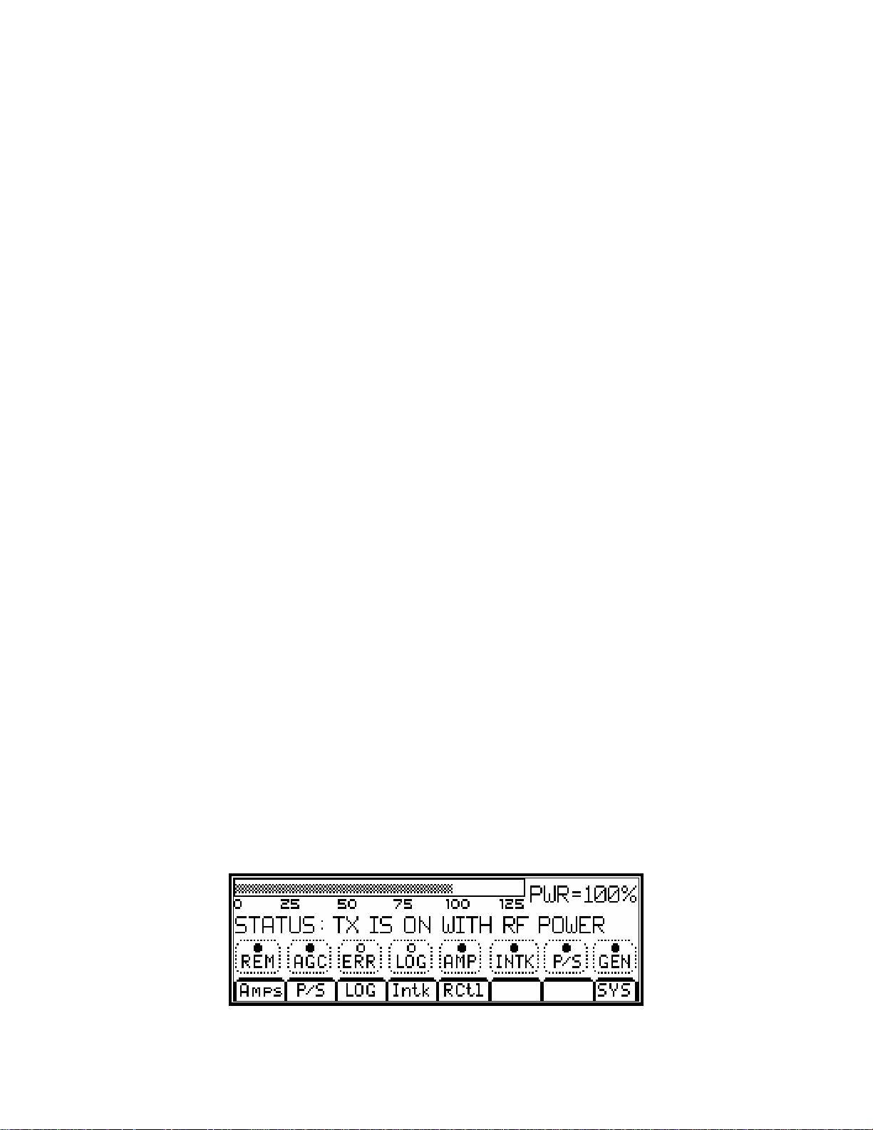
user via the touchpad. Figure 4 shows the LCD main menu, which shows the present status of the amplifier along
with the selections of submenus.
Figure 4 Main Menu Screen
PUB07-03 Rev 1 July 17, 2007 07-03-2 MXi Half Pallet Operations and Maintenance
MXi HALF PALLET OPERATIONS AND MAINTENANCE
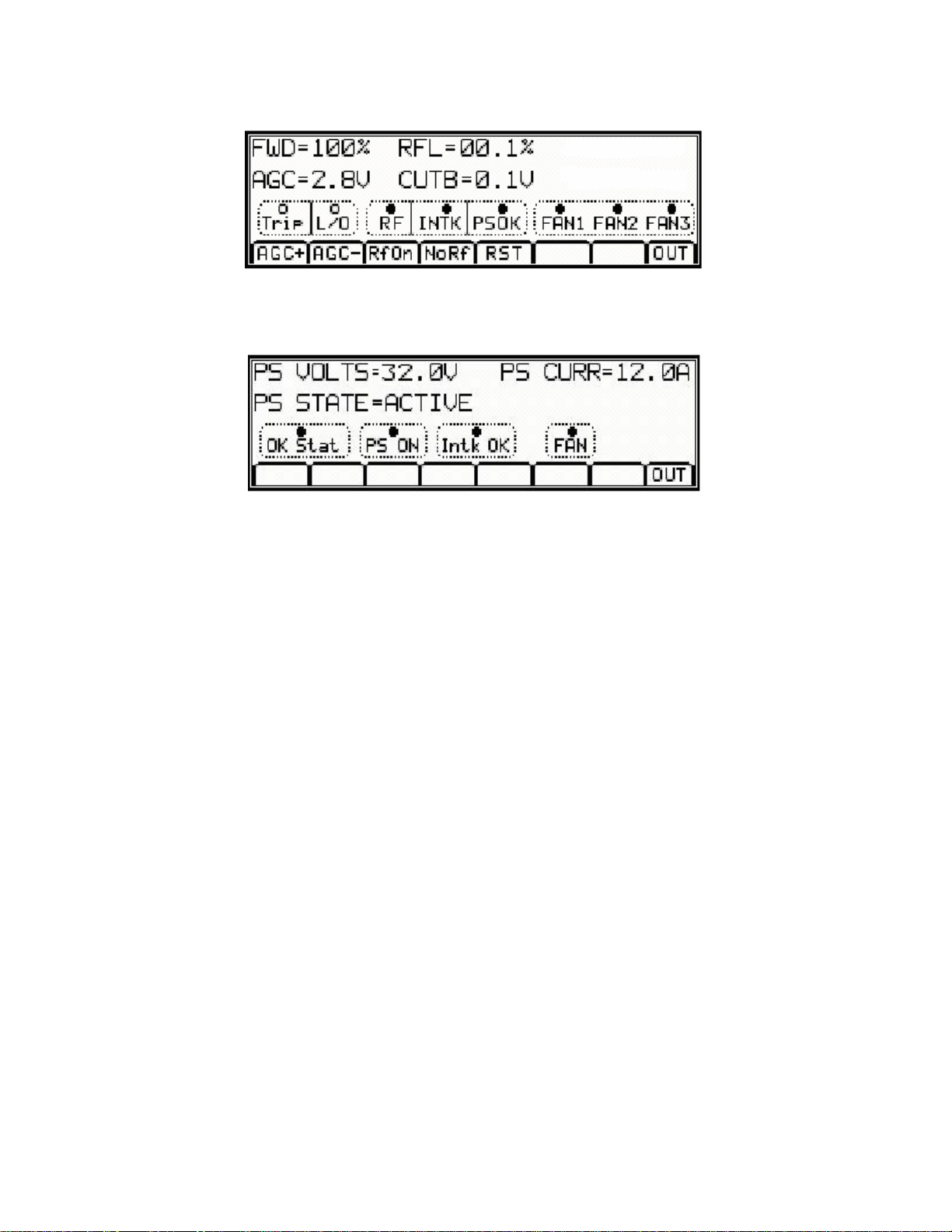
Forward (FWD) and Reflected power (RFL), AURal power, AGC and CUTBack (VSWR) control voltage, as well
as the heatsink TEMPerature (Optional) can be displayed by selecting the AMP submenu as shown in Figure 5.
Figure 5 Amplifier (AMP) Submenu
Pressing the power supply ‘P/S’ submenu from the Main Menu will display the power supply voltage and current
consumption as well as its status.
Figure 6 Power Supply (P/S) Submenu Screen
For complete documentation regarding the Controller, see the publication MXi Controller Board.
PUB07-03 Rev 1 July 17, 2007 07-03-3 MXi Half Pallet Operations and Maintenance

MXi HALF PALLET OPERATIONS AND MAINTENANCE
3 AMPLIFIER INSTALLATION AND STARTUP
The MXi Amplifier was fully tested at LARCAN before it was delivered. Under normal circumstances, the
transmitter can be fully operational with minimal setup when turned ON. However, a good practice is to take the
“start from scratch” approach, which means that you should take precautionary measures before the amplifier is
allowed to run at full rated power. These important steps will avoid any catastrophic failures at start-up. The
procedure described is essentially the same approach taken at the factory with a new and untested transmitter.
This also applies if there is a need to completely replace a major sub-assembly in the transmitter.
3.1 BEFORE APPLYING AC TO THE UNIT
Pay careful attention to items 1 to 3 before applying AC to the amplifier. These are initial steps that must be
observed and followed for proper and safe operation of the amplifier.
1. Termination
• Ensure that the amplifier is properly terminated with a suitable load. This can be into a dummy load or into
the transmitter output system. A 50 Ohm, 100W load with at least –20dB return loss (1.2 VSWR) is
recommended. Preferably, directional couplers with known coupling levels at the frequency of interest
should be connected at the input and output of the band-pass filter. These points are very useful in
determining absolute power levels and losses and for use as an RF sample for monitoring purposes. See
Figure 15 for a typical Eclipse transmitter test equipment setup.
2. Interlocks
Antenna or Load interlocks must be connected to the amplifier to avoid damage to the equipment and to the
output section. Interlocking is provided at the INTERLOCK terminal board located on the rear panel. If this
interlock is open, the B+ to the amplifier will shut down, including the cooling fans. DO NOT replace this
interlock with a jumper.
Figure 7 Rear Panel Showing Interlock Terminal Board
3. Power At Minimum
• Initially, the Exciter or Channel Processor’s RF output should be at minimum level. Adjust the OUTPUT
LEVEL control for a minimum output.
3.2 APPLYING AC TO THE UNIT
• Check that the AC voltage available to the amplifier ranges from 90-264VAC. If so, proceed to applying
the power to the AC INPUT of the amplifier
• Once the AC is applied to the unit, the Control Power Supply turns ON and applies +12V to the MXi
Controller.
• Observe that the Power-Up screen is displayed on the LCD, followed by the Main Menu.
PUB07-03 Rev 1 July 17, 2007 07-03-4 MXi Half Pallet Operations and Maintenance

MXi HALF PALLET OPERATIONS AND MAINTENANCE
Figure 8 Main Menu
3.3 BEFORE TURNING THE AMPLIFIER ON
From the Main Menu, the status of the amplifier is displayed and shows if the amplifier is ready for operation.
Status legends, when lit, such as the INTK (INTERLCOK), usually signify OK conditions and that the transmitter is
ready to be turned ON.
Check that all of the following conditions are met:
1. EXCITER or Channel Processor is Ready.
• Usually in the application of AC, the Exciter goes through its warm-up sequence. Ensure that it has done
so.
4. POWER METERING is at Zero.
• On the LCD (see Main Menu display in Figure 8), the PWR should be at 000% and the STATUS should
be TX IS OFF, NORMALLY.
5. MXi CONTROLLER is ready.
• If there were prior faults, clear them by pushing the RESET button.
6. INTERLOCKS are closed or OK.
• Interlocks and Status are OK.
Figure 9 Interlocks Status
7. AGC control is DISABLED at this time.
• Push the AGC button on the touchpad so that it is NOT selected.
Figure 10 AGC OFF
8. The Amplifier is in LOCAL mode.
• Push the REM button so that it is not lit.
9. The TX is OFF.
PUB07-03 Rev 1 July 17, 2007 07-03-5 MXi Half Pallet Operations and Maintenance
 Loading...