

Larcan MXD5U Users Manual
TECHNICAL SERVICE MANUAL
MXD5U AMPLIFIER
LARCAN INC.
228 AMBASSADOR DRIVE
MISSISSAUGA, ONTARIO
CANADA L5T 2J2
PHONE: (905) 564-9222
FAX: (905) 564-9244
EMAIL: techservices@larcan.com
PUB09-03 Rev 0
16 April, 2009

MXD5U OPERATIONS AND MAINTENANCE
CONTENTS
1 AMPLIFIER ......................................................................................................................................................................1
2 CONTROLLER.................................................................................................................................................................2
2.1 CONTROL BOARD ASSEMBLY AND JUMPER SETTINGS ..................................................................................................2
2.2 REMOTE CONTROLS AND THE MXD5U FRONT PANEL ON/OFF BUTTON....................................................................4
2.3 EXTERNAL REMOTE CONTROL CONNECTIONS..............................................................................................................6
2.3.1 Remote Command Inputs.....................................................................................................................................6
2.3.2 Remote Telemetry Outputs...................................................................................................................................6
2.3.3 Remote Status Outputs......................................................................................................................................... 7
2.3.4 External1 Interlock..............................................................................................................................................7
2.4 EXTERNAL TRANSMITTER IN TERLOCK .........................................................................................................................8
3 AMPLIFIER INSTALLATION AND STARTUP..........................................................................................................9
3.1 BEFORE APPLYING AC TO THE UNIT ............................................................................................................................9
3.2 APPLYING AC TO THE UNIT..........................................................................................................................................9
3.3 BEFORE TURNING THE AMPLIFIER ON .........................................................................................................................9
3.4 AMPLIFIER ON SEQUENCE..........................................................................................................................................10
3.4.1 Tur ning ON the Amplifier.................................................................................................................................10
4 TEST AND TROUBLESHOOTING .............................................................................................................................11
4.1 BENCH TEST PROCEDURES .........................................................................................................................................11
4.1.1 Front-End Module Bench Test Procedure.........................................................................................................11
4.1.2 IPA1 Bench Test Procedure...............................................................................................................................11
4.1.3 Pallet 21B1751 Bench Test Procedure..............................................................................................................11
4.2 BASIC TROUBLESHOOTING TECHNIQUES ....................................................................................................................12
4.2.1 Amplifier Completely OFF.................................................................................................................................12
4.2.2 No RF Output.....................................................................................................................................................12
4.2.3 Output Reduced to 25%.....................................................................................................................................12
5 MAINTENANCE.............................................................................................................................................................13
5.1 DAILY.........................................................................................................................................................................13
5.2 MONTHLY...................................................................................................................................................................13
5.3 SEMI-ANNUALLY AND ANNUALLY .............................................................................................................................13
5.4 TRANSMITTER COOLING SYSTEM ...............................................................................................................................13
6 TEST EQUIPMENT SETUP..........................................................................................................................................14
7 SPECIFICATIONS .........................................................................................................................................................15
7.1 ELECTRICAL ...............................................................................................................................................................15
7.2 ENVIRONMENTAL.......................................................................................................................................................15
7.3 COOLING ....................................................................................................................................................................15
7.4 DIMENSIONS ...............................................................................................................................................................15
7.5 SHIPPING WEIGHT ......................................................................................................................................................15
FIGURES
FIGURE 1 MXD5U AMPLIFIER HEATSINK ASSEMBLY..................................................................................................................1
FIGURE 2 CONTROLLER BOARD....................................................................................................................................................2
FIGURE 3 FRONT PANEL ...............................................................................................................................................................2
FIGURE 4 REMOTE COMMAND INPUTS..........................................................................................................................................6
FIGURE 5 REMOTE TELEMETRY OUTPUTS ....................................................................................................................................6
FIGURE 6 REMOTE STATUS OUTPUTS ...........................................................................................................................................7
FIGURE 7 REAR PANEL SHOWING INTERLOCK TERMINAL BOARD................................................................................................9
PUB09-03 Rev 0 April 16, 2009 09-03-i MXi005U Operations and Maintenance

MXD5U OPERATIONS AND MAINTENANCE
FIGURE 8 TEST EQUIPMENT SETUP.............................................................................................................................................14
FIGURE 9 - FRONT END AMPLIFIER, MXD5U.............................................................................................................................16
FIGURE 10 - IPA ASSEMBLY, MXD5U.......................................................................................................................................17
FIGURE 11 - AMPLIFIER PALLET, MXD5U.................................................................................................................................18
FIGURE 12 MXD5U CONTROL BOARD ASSEMBLY ....................................................................................................................19
PUB09-03 Rev 0 April 16, 2009 09-03-ii MXi005U Operations and Maintenance
MXD5U OPERATIONS AND MAINTENANCE
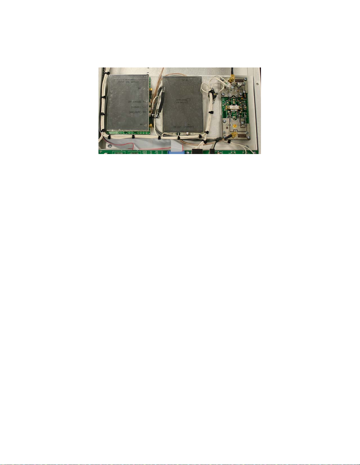
1 AMPLIFIER
The RF section of the MXD5U Amplifier consists of a heatsink assembly that includes three cascaded broadband
amplifier modules and a directional coupler.
Figure 1 MXD5U Amplifier Heatsink Assembly
Also mounted on the heatsink is a thermal switch that protects the amplifier from over temperature conditions.
Figure 1 shows the layout of this assembly.
PUB09-03 Rev 0 April 16, 2009 09-03-1 MXD5U Operations and Maintenance
MXD5U OPERATIONS AND MAINTENANCE
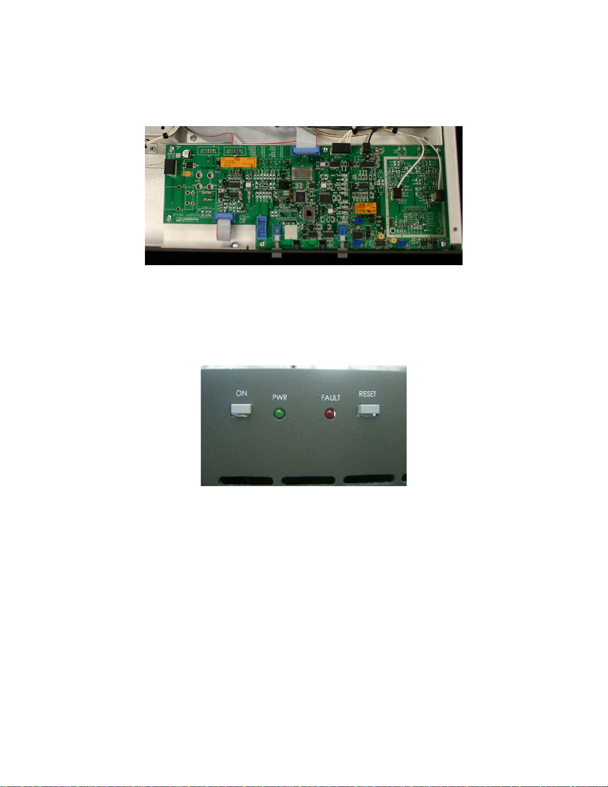
2 CONTROLLER
The control board (Assembly 31C1971) is a single-circuit assembly that provides all of the control functions
required for the transmitter on a single circuit board. This board can be configured for a number of different
transmitter types, power levels, transmission standards and options.
Figure 2 Controller Board
The control board provides local front panel interface via ON/OFF and RESET buttons. The board implements
controls/status/telemetry for remote control through a rear panel connector that will interface to a typical remote
control systems (such as Moseley or Gentner). An RS232 serial port is also provided to allow the operator to
access the transmitter through an external computer (with the appropriate software). The control board has RF
detectors for forward and reflected power and all the circuitry to support AGC/VSWR/Cutback functions. Circuitry
to control and monitor the +28V power supply is also included on this board.
Figure 3 Front Panel
2.1 CONTROL BOARD ASSEMBLY AND JUMPER SETTINGS
Figure 9 shows the assembly diagram for the control board (Part No 31C1897A2) that performs all the control,
monitoring, RF detection and communication functions.
There are a number of jumpers on this board that are factory set and should not be altered in the field without
consulting Larcan Technical Services first. Changing the jumper settings may result in improper operation of the
transmitter.
The factory jumper settings are given here in the case that either a jumper is dislodged during shipping or has
been removed for any other reason.
Note: This circuit board is used for a number of transmitter models and a number of components and jumpers are
not installed or used for this transmitter model. We will only detail the jumpers that are used in the MXD5U.
E1 BDM Enable
Allows connection of the BDM program cable to the board
Setting = NORM for all MXD5U transmitters
PUB09-03 Rev 0 April 16, 2009 09-03-2 MXD5U Operations and Maintenance

MXD5U OPERATIONS AND MAINTENANCE
E2 Not used in the MXD5U transmitter
Setting = no jumper installed
E3 Not used in the MXD5U transmitter
Setting = no jumper installed
E4 Not installed in this assembly
E5 Front Panel ON/OFF button Mode
This jumper determines the function of the Front Panel ON/OFF button
If E5 is in the ‘INT’ position, Remote ON/OFF Controls are disabled, Local Controls Only
If E5 is in the ‘EXT’ position, Remote ON/OFF Controls are enabled, Local OFF Control Only
More detail on this function is given in Section XX of this manual
Setting = EXT for all MXD5U transmitters
E6 Transmitter Switching Interlock
This may have either a two pin header or may be permanently jumpered with bus wire
If there is a two pin header, then it requires a shorting jumper
If this is not shorted, then the transmitter will not turn ON.
Setting = Jumper installed
E7 Not used in the MXD5U transmitter
Setting = no jumper installed
E8 Not installed in this assembly
E9 Not installed in this assembly
E10 Not installed in this assembly
E11 Forward Power Sample Gain
Sets either High or Low gain from the DC sample received from the RF coupler
Set to obtain a voltage between 4.5 and 8V at TP2 for full power RF output
Can be either in the HI or LO position depending on channel and RF coupler
Typical Setting = LO for most MXD5U transmitters
E12 Not installed in this assembly
E13 Not installed in this assembly
E14 Not installed in this assembly
E15 Reflected Power Sample Gain
Sets either High or Low gain from the DC sample received from the RF coupler
Set to obtain a voltage between 4.5 and 8.0V at TP4 for 10% reflected power
Can be either in the HI or LO position depending on channel and RF coupler
Typical Setting = HI for most MXD5U transmitters
E16 AGC Disable
This jumper disables the AGC circuitry
DO not install this jumper. It is meant for factory setup
Setting = not Installed for all MXD5U transmitters
PUB09-03 Rev 0 April 16, 2009 09-03-3 MXD5U Operations and Maintenance

MXD5U OPERATIONS AND MAINTENANCE
E18 Direct Vswr Relay reset from the Remote Reset Command
This jumper allows the Remote Reset Command to directly clear the VSWR trip relay
Setting = Installed for all MXD5U transmitters
E19 Forward Power Detection Type
Setting = PK for all MXD5U transmitters
2.2 POWER CALIBRATION, AGC AND CUTBACK SETUP
HIGH VOLTAGE
RISK OF EXPOSURE TO VOLTAGES UP TO 260VAC
Use particular caution near the power supply’s transformer terminals.
The following setup is for the overall assembly of the MXD5U transmitter. It assumes that all individual
components in the assembly have been tested and biased, including the Control Board, the Amplifier Boards and
the Directional Coupler.
Note that the tests below are factory specific and therefore do not include the use of an Output Mask Filter. If one
is available, it can be inserted and setup performed as described in the procedure, with the following exceptions.
- perform power calibration at the filter output calibrating to a 5W level
- installation and alterations of test loads are done at the filter output, not transmitter RF Output.
PLEASE NOTE SAFETY WARNING ABOVE.
Connect a jumper wire across the terminals of the INT’K (External Interlock) terminal block at the rear panel. This
is temporary and must be removed when tests are completed.
Confirm Amplifier Bias
Terminate RF Out with 50R (min 20W rating). Apply no rf drive.
Turn ON Amplifier at front panel. Check for 28VDC at Amplifiers.
Check Amplifier Bias Currents: Front End Amplifier: 0.2-0.3A, IPA:1A, Amplifier Pallet: 1.0A
Power Calibration
Set R105 completely CCW. Ensure J8 is connected.
Remove all Control board jumpers except;
- E7 and E8 IN
- E2 to RS232
Monitor TP1. Adjust R39 for 0.02VDC.
Apply signal to get full power + filter losses at output. Approx 6W.
Check out-of-band shoulder levels at 6W for the broadcast channel before proceeding.
Set E5 to get 4-8V at TP1. Monitor TP2; adjust R46 for 4.00V.
Adjust R79 for 100% meter reading.
Increase Power to get 110%. Remove E7 and set R73 to get 4.0V on TP3. Meter should again read 100%.
PUB09-03 Rev 0 April 16, 2009 09-03-4 MXD5U Operations and Maintenance
 Loading...