


FM-250 FM BROADCASTING EXCITER
FM-250
250W STEREO
TRANSMITTER/EXCITER
TECHNICAL MANUAL
LARCAN Denver Office (LARCAN-TTC)
1390 Overlook Drive #2, Lafayette, CO 80026 USA
Tel: 303-665-8000 Fax: 303-763-9900
E-Mail: sales@earthnet.net Web: www.larcan.com
Issue Date: 21 Jan 2003

FM-250 FM BROADCASTING EXCITER
NOTE
AMENDMENT
Please take note that any reference to 230V and 50Hz in this manual should
be read as 110V and 60Hz respectively.
Issue Date: 21 Jan 2003

FM-250 FM BROADCASTING EXCITER
FM-250
250W STEREO TRANSMITTER/EXCITER
TECHNICAL MANUAL
CONTENTS:
1. General Description
2. Technical Specifications
3. Operating Information
4. Installation Information
5. Technical Information
6. Maintenance information
LARCAN Denver Office (LARCAN-TTC)
1390 Overlook Drive #2, Lafayette, CO 80026 USA
Tel: 303-665-8000 Fax: 303-763-9900
E-Mail: sales@earthnet.net Web: www.larcan.com
Issue Date: 21 Jan 2003

FM-250 FM BROADCASTING EXCITER
Issue Date: 21 Jan 2003

FM-250 FM BROADCASTING EXCITER
INTRODUCTION
This manual contains the operating, technical and installation information for the NCI FM-250
FM Broadcasting Exciter. The Exciter forms part of a new range of Professional FM Broadcast
Exciters produced by Broadcast Solutions Electronics (Pty) Ltd and supplied by LARCAN
USA in the United States.
1. The FM-250 Exciter forms a compact, solid state FM Broadcast transmitter with a RF
output in excess of 250W in the FM Broadcasting band (87.5MHz to 108MHz). The unit is
housed in a 19-inch rack mount case occupying only a 2U space. The Exciter features a
range of customer options including a built in, high quality Stereo coder.
2. The FM-250 Exciter offers a standard specification, better than the general requirements of
the major broadcasters in the world. This level of performance is only found in the best
equipment that the market has to offer.
3. The following basic versions are available:
a) FM-250 (W) Wideband MPX Exciter (For use with composite input).
b) FM-250 (S) Stereo Exciter (With built in Stereo coder and Audio Limiter).
c) FM-250 (M) Mono Exciter (With built in Mono input filter and Audio Limiter).
Issue Date: 21 Jan 2003

FM-250 FM BROADCASTING EXCITER
FM-250
250W STEREO TRANSMITTER/EXCITER
TECHNICAL MANUAL
General Description
LARCAN Denver Office (LARCAN-TTC)
1390 Overlook Drive #2, Lafayette, CO 80026 USA
Tel: 303-665-8000 Fax: 303-763-9900
E-Mail: sales@earthnet.net Web: w ww.larcan.com
Issue Date: 21 Jan 2003

FM-250 FM BROADCASTING EXCITER
Issue Date: 21 Jan 2003

FM-250 FM BROADCASTING EXCITER
GENERAL DESCRIPTION
1. STRUCTURE.
The Exciter comprises of the following modules.
a) Synthesizer/Modulator module (980507).
b) Control/Monitoring module (980508).
c) 250W RF PA module (980510).
d) 250W Power supply module (980515).
e) Display module (980509).
f) Stereo coder/Limiter (980512). (Optional).
g) Fan Psu module (980518).
2. FEATURES.
The FM-250 Exciter has standard features including the following;
a) Remote/Internal frequency selection (standard) with Thumbwheel switch option
available.
b) Remote telemetry with voltage free contacts (standard).
c) +48V Battery operation (standard).
d) Wideband input (MPX) with two auxiliary inputs (SST/SCA/RDS).
e) Comprehensive metering including VU meters. (Built in Stereo decoder).
f) ALC built in for absolute control of RF output power.
g) Comprehensive protection built in.
3. BLOCK DIAGRAM DESCRIPTION.
Issue Date: 21 Jan 2003

FM-250 FM BROADCASTING EXCITER
Refer to the Front panel layout in figure 1, Rear panel controls and connectors in figure2
and the Block diagram of FM-250 in Figure 3
Issue Date: 21 Jan 2003
FM-250 FM BROADCASTING EXCITER
Issue Date: 21 Jan 2003
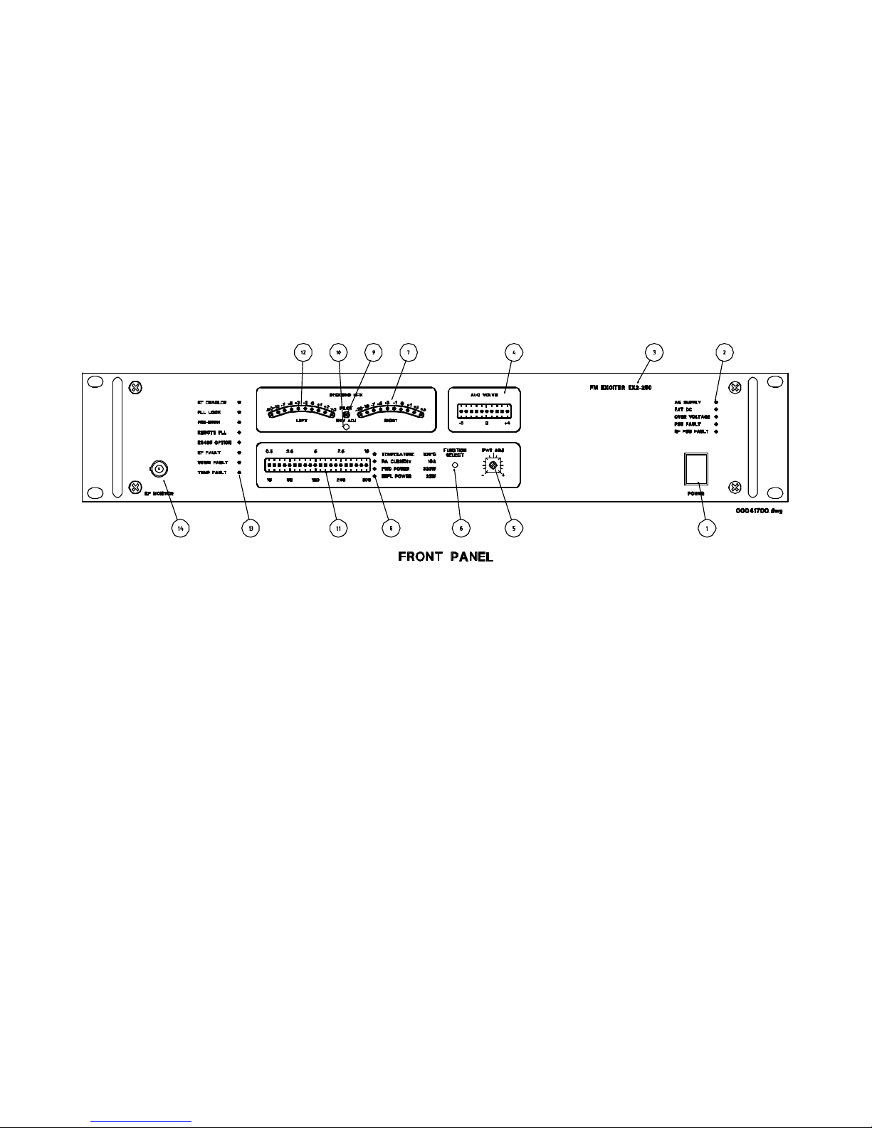
Figure 1: FM-250 Front Panel Controls

FM-250 FM BROADCASTING EXCITER
Issue Date: 21 Jan 2003
Figure 2: FM-250 Rear Panel Controls and Connectors

FM-250 FM BROADCASTING EXCITER
Issue Date: 21 Jan 2003

FM-250 FM BROADCASTING EXCITER
Issue Date: 21 Jan 2003
Figure 3: Block diagram of FM-250
STEREO
CODER
980512
OV
OV
LEFT (XLR)
RIGHT (XLR)
PRE-EMPH
(SWITCH)
SYNTHESISER
980507
OV
MPX (I/P)
OV
AUX 1 (I/P)
OV
AUX2 (I/P)
SYNTH
REMOTE
(D-15)
PL1
PL2
PL3
SK2
SK3
SK4
PL2
MPX OUT
RF P.A.
250W
980510
OV
RF OUT
(N TYPE)
RF OUT
SK1
CONTROL PCB
980508
BACK PANEL
INPUTS
OV
PILOT OUT
(BNC)
REAR PANEL
SK1
PL4
10 way ribbon
cable
PL4
REMOTE
TELEMETRY
REAR PANEL
(D-25)
PL7
DEVIATION
ADJ.
(OPTIONAL)
PL3
PSU
PL4
PL5
THUMBWHEEL
(OPTION)
PSU PCB
980508
PL1
OV
SK1
ALC
TEMP
CNTRL
FWD
REFL
PL3 PL1 PL2 SK1 SK2
PL1
PL2
PL3
DISPLAY
PCB
980509
26 way ribbon
cable
PL6
20 LED MULTIMETER
STEREO VU METER
PILOT INDICATOR
FAULT INDICATORS
FUNCTIONAL INDICATORS
DEVIATION ADJ. (OPTIONAL)
RF POWER ADJ.
RS485 (OPTIONAL)
REAR PANEL
PL1
PL8
500VA
TRANSFORMER
RF MONITOR
FRONT PANEL
(BNC)
OV 230V
50Hz
(IEC INPUT)
E
N
L
0V
+48V
O/P
AUX.
VOLTS
+24V
AC
+48V
AC
230V
50Hz
FRONT
PANEL
POWER
SWITCH
SK1/1
25A
BRIDGE
PL4
PL1
+
~
~
SK1
AUX PSUMAIN PSU
8A
10A
D.C.
INPUT
SK4 SK1/3
PL3
FAN
PL2
250W STEREO EXCITER BLOCK SCHEMATIC
25A
BRIDGE

FM-250 FM BROADCASTING EXCITER
a) SYNTHESIZER AND MODULATOR (980507)
The digital synthesizer derives the final operating frequency from a 10MHz reference (TCXO)
using a PLL (Phase lock loop) and dividers. The frequency can be selected Locally (In 100kHz
steps via rotary BCD switches) or Remotely (via a external parallel control). The direct carrier
modulator uses special techniques to obtain very low distortion and high stereo channel
separation (>60dB). This level of performance is not normally found on competitive equipment,
especially at low audio frequencies.
The Synthesizer is equipped with four modulating inputs, three of which are external (BNC's)
and one internal (SMB) for use with optional Stereo coder.
The synthesizer is protected from Out of Lock and Out of Band operation by removing the RF
Output when either of these conditions exists.
b) RF PA MODULE (980510)
The RF output (Nominally +10dBm) from the synthesizer buffer is amplified by a three stage RF
power amplifier to obtain the final output power of >250W. The final device is operated in
push -pull mode to obtain high efficiency. All devices are operated well within their ratings.
Wideband techniques are used throughout the PA and a built in harmonic filter is used at the
output to suppress all harmonics. Directional couplers are used to sample the output for control
and monitoring purposes.
A temperature-sensing device is provided for thermal monitoring. This device is situated at the
final RF Stage to provide accurate temperature monitoring of the RF PA Heatsink.
Current and voltage sensing is provided for control and monitoring purposes along with the
ALC circuit, which controls and monitors the RF output power.
A Series regulator is used to ensure protection and utilizes three parallel devices for maximum
reliability.
c) CONTROL MODULE (980508)
The control Pcb provides the standard telemetry functions and interconnections for the Exciter.
The unit receives two dc inputs, one from the external battery supply and one from the rectified
a/c supply and has a ‘on board’ low power switching power supply. The various voltages are
distributed to the other modules via the Control Pcb.
Forward and Reflected RF Inputs are processed and distributed for ALC control and
monitoring purposes. RF PA current, Voltage and Temperature are also processed and their
voltages distributed.
Various voltage free contacts are provided for telemetry purposes and are Link selectable for
o/c or s/c condition.
d) POWER SUPPLY MODULE (980515)
Issue Date: 21 Jan 2003

FM-250 FM BROADCASTING EXCITER
The power supply module contains the smoothing capacitors for the ‘off board’ 230V 50Hz a/c
mains transformer/bridge rectifier combination. This +52V nominal smoothed supply is then
distributed to a choke/capacitor filter at the module. This type of arrangement eliminates all
ripple and therefor any AM products on the transmitter, even when the a/c input voltage is
extremely low. The +48V (nominal) external battery supply is combined off the module with the
smoothed supply via isolating diodes. The various voltages are then distributed to the other
modules.
Auxiliary supplies are generated for use in the RF PA regulator stage and Modules.
e) DISPLAY MODULE (980509)
The display module provides the Local user functions and alarm indications at the Exciter front
panel. The display has three functional meters, which allow instant viewing of multiple functions.
1) Multimeter: Provides push button selectable functions for Forward power, Reflected
power, PA current and Heatsink temperature.
2) ALC meter: Dedicated meter for instant viewing of ALC voltage and alarm.
3) MPX VU meter: Active peak detection meters for Left and Right channels, derived from
built in Stereo decoder. This provides instant viewing of Transmitter deviation from Left and
Right channels. The Stereo pilot indication is also provided with the meter.
Alarm indications are provided by Front panel LED’s, enabling instant viewing of transmitter
functions. Front panel adjustments are available for control of RF Output power and Deviation
level.
Connection for the optional RS485 Module is provided on the Display, enabling remote viewing
of Meter functions.
f) STEREO CODER MODULE (980512) (optional)
This optional module allows the user to facilitate a very high quality stereo signal on board the
Exciter and provides all the necessary functions such as Pre emphasis switching, Mono- Stereo
switching with the added advantage of a built in Audio Limiter. The module accepts Left and
Right audio inputs (600 ohms balanced) and after Limiting and filtering is converted into the
Stereo multiplex format via a new digital stereo multiplexer. A 100kHz Linear phase filter is
used at the output with comprehensive phase adjustment to obtain absolute transparency.
A 19kHz Pilot signal output is provided for supplementary signal use.
g) BACK PANEL CONNECTIONS
The 110V 60Hz a/c power input is connected via an IEC connector whilst the +24 dc input is
connected via Binding terminals. Back panel Fuses are provided for maximum protection.
Standard telemetry output is provided via a 25 pin D connector, while the Remote frequency
control has a 15 pin D connector.
Issue Date: 21 Jan 2003

FM-250 FM BROADCASTING EXCITER
There is provision for three (50-ohm BNC female) external modulating inputs, one for external
MPX (600 ohms unbal. or 1.2k ohms BAL.) And two for auxiliary use (20k ohms unbal.).
The RF Output is via an N Type (50-ohm) connector.
Optional connectors include two XLR (F) connectors (for Stereo coder), plus Pre- emph slide
switch with a 9 pin D connector for the RS485 module.
h) MONO FILTER (optional)
The Mono filter option provides the user with a XLR (F) 600 ohm balanced input and 15kHz
low pass filter with an internal output connection to the Synthesizer and modulator. Preemphasis switching (50uS or 75uS) is provided on board and is switched via the Pre-emphasis
switch on the back panel. An Audio Limiter is supplied as standard issue with internally
adjustable threshold.
Note: The following modules are common to the range of Exciters produced by NCI
Electronics.
• Synthesizer module
• Control module
• Stereo coder (option)
• Mono filter (option)
Issue Date: 21 Jan 2003

FM-250 FM BROADCASTING EXCITER
250W STEREO TRANSMITTER/EXCITER
TECHNICAL MANUAL
Technical Specifications
LARCAN Denver Office (LARCAN-TTC)
1390 Overlook Drive #2, Lafayette, CO 80026 USA
Tel: 303-665-8000 Fax: 303-763-9900
E-Mail: sales@earthnet.net Web: www.larcan.com
Issue Date: 21 Jan 2003

FM-250 FM BROADCASTING EXCITER
AF RESPONSE
TECHNICAL SPECIFICATIONS
GENERAL RF SPECIFICATIONS
FREQUENCY RANGE 87.5 MHz to 108MHz
FREQUENCY CONTROL PLL Synthesizer
FREQUENCY INCREMENTS 100kHz steps (Local and Remote control)
FREQUENCY STABILITY ± 2ppm (10MHz TCXO)
RF OUTPUT POWER ≥ 250W (Adjustable via front panel control)
RF HARMONIC SUPPRESSION ≥ 70dB
RF SPURIOUS SUPPRESSION ≥ 75dB
OUT OF LOCK ATTENUATION ≥ 80dB
OUT OF BAND ATTENUATION ≥ 80dB (87.5MHz ≤ F ≤ 108MHz)
AM NON SYNCHRONOUS NOISE ≤ -60dB (Filtered 20Hz to 20kHz)
AM SYNCHRONOUS ≤ -60dB (Filtered 20Hz to 20kHz)
MEAN CARRIER VARIATION ≤ ±200Hz
WIDEBAND COMPOSITE OPERATION
BASEBAND RESPONSE
STEREO SEPARATION
STEREO DISTORTION
WIDEBAND S/N RATIO ≥ 80dB (20Hz to 20kHz) 50uS de emph.
INPUT IMPEDANCE 1k2 ohms balanced (other on request)
DEVIATION SENSITIVITY 3.5V p-p for ±75kHz deviation (adj.)
STEREO OPERATION (With built in Stereo coder/Limiter)
STEREO SEPARATION ≥ 60dB (30Hz to 15kHz)
STEREO DISTORTION ≤ 0.1% (30Hz to 15kHz)
STEREO S/N RATIO ≥75dB (20Hz to 20kHz) 50uS de emph.
MONO/STEREO CROSSTALK ≥ 50dB (30Hz to 15kHz)
INPUT IMPEDANCE 600 ohms balanced (XLR)
DEVIATION SENSITIVITY +6dBm for ±40kHz deviation (adj.)
AUDIO LIMITER SENSITIVITY 10dBm nom. for 62.5kHz deviation (adj.)
ATTACK TIME ≤ 2mS for increased 10dB I/P step
DECAY TIME ≥ 80mS for a decreased 10dB I/P step
LIMITER DISTORTION ≤ 0.35% (10dB into limiting)
LIMITER THRESHOLD Internally adjustable
≤ 0.2dB (30Hz to 100kHz)
≥ 60dB (30Hz to 15kHz)
≤ 0.1% (30Hz to 15kHz)
≤ ±0.3dB (30Hz to 15kHz)
Issue Date: 21 Jan 2003

FM-250 FM BROADCASTING EXCITER
MONO OPERATION (With built in Mono filter)
AF RESPONSE ≤ ±0.3dB (30Hz to 15kHz)
MONO DISTORTION ≤ 0.1% (30Hz to 15kHz)
S/N RATIO ≥ 80dB (20Hz to 20kHz) 50uS de emph
INPUT IMPEDANCE 600 ohms balanced (XLR)
DEVIATION SENSITIVITY +6dBm for ±40kHz deviation (adj.)
ATTACK TIME ≤ 2mS for increased 10dB I/P step
DECAY TIME ≥ 80mS for a decreased 10dB I/P step
LIMITER DISTORTION ≤ 0.35% (10dB into limiting)
LIMITER THRESHOLD Internally adjustable
ENVIRONMENTAL SPECIFICATIONS
A/C INPUT POWER 110V ±10% (other on request)
A/C FREQUENCY VARIATION 60Hz ±5% (other on request)
DC INPUT POWER +24V nominal Battery
STORAGE TEMPERATURE -40°C to +60°C
OPERATING TEMPERATURE -10°C to +45°C
RELATIVE HUMIDITY 20% to 90% (non condensing)
OPERATING ALTITUDE ≤ 2500m above sea level
COOLING SYSTEM Forced air (4 x 24Vdc blowers)
PHYSICAL DIMENSIONS 480mm x 485mm x 88.8mm
PHYSICAL MASS Approximately 16kg
STANDARD ALARM SETTINGS AND LOCAL INDICATIONS (adjustable)
RF FAULT INDICATION ≤ 175W (Red led on front panel)
VSWR FAULT INDICATION ≥ 20W (Red led on front panel)
VSWR FAULT TRIP INDICATION ≥ 25W (Red led/front panel/10Sec re-cycle)
TEMP FAULT INDICATION ≥ 55°C (Red led on front panel)
TEMP TRIP INDICATION ≥ 65°C (Red led on front panel)
ALC FAULT INDICATION Out of range (Red led/front panel meter)
PSU FAULT INDICATION Internal Psu fault (Red led on front panel)
RF PSU FAULT INDICATION RF PA Psu fault (Red led on front panel)
OVERVOLTAGE FAULT ≥ +52V at Control (Red led on front panel)
The unit has a number of operational customer link options, which should normally be
configured before delivery. Consult Control module technical description section.
• RF Power backed off with high temperature.
Issue Date: 21 Jan 2003

FM-250 FM BROADCASTING EXCITER
• RF Power backed off with high VSWR.
• RF Power backed off with high RF PA Current.
Issue Date: 21 Jan 2003

FM-250 FM BROADCASTING EXCITER
250W STEREO TRANSMITTER/EXCITER
TECHNICAL MANUAL
Operating Information
LARCAN Denver Office (LARCAN-TTC)
1390 Overlook Drive #2, Lafayette, CO 80026 USA
Tel: 303-665-8000 Fax: 303-763-9900
E-Mail: sales@earthnet.net Web: www.larcan.com
Issue Date: 21 Jan 2003

FM-250 FM BROADCASTING EXCITER
OPERATING INFORMATION
FRONT PANEL
1. POWER ON/OFF SWITCH
The front panel On/Off switch connects the External A/C and D/C supplies to the equipment.
2. POWER ADJUST CONTROL
This single turn potentiometer is used to set the RF output power via the internal ALC
Circuit. Fully anti-clockwise gives minimum power (≤ 25W) while clockwise gives
Maximum power (≥ 250W).
3. DEVIATION ADJUST
This single turn potentiometer is used to fine trim the Transmitter final deviation level.
The standard variation is ± 1.5dB (other on request). This controls the total deviation
Level .
Note: When the stereo coder option is installed, the built in Limiter controls the maximum
Deviation level of the Left and Right program inputs and adjustment of this level is done
Internally, to customers requested level.
4. MULTIMETER
The Multimeter comprises a linear scale, 20 led (green) custom bar display. The meter
has a push button selector with individual LED's (yellow) for indicating the four selectable
Functions.
• Temperature: RF PA Heatsink temperature with 100°C f.s.d.
• RF PA Current: RF final stage current with 10A f.s.d.
• RF Forward power: RF Output power with 320W f.s.d.
• RF Reflected power: RF Output Reflected power with 32W f.s.d.
5. ALC METER
This dedicated 10 led (9 green and 1 red) bar display provides instant information on the
ALC loop control function and voltage. The meter indicates the dc control voltage at the
Gate of the final RF Mosfet stage and as such gives the user instant feedback on the status
of the ALC loop.
The meter scale is -5V to +4V (1volt per led) with the +4V led (red) indicating ALC ‘out
of range’.
6. VU METERS
This dedicated stereo meter is used to indicate the dynamic peak deviation of the Left
and Right channels. This provides the user with instant visual information on the status of
the system modulation.
The meters operate to the DIN 45406 specification with precision Full wave peak
Issue Date: 21 Jan 2003

FM-250 FM BROADCASTING EXCITER
detection.
The signals are derived from the built in stereo decoder and calibrated accordingly.
The VU meter scales are as follows:
LEFT CHANNEL RIGHT CHANNEL LED STATUS
+3dBm +3dBm Over deviation (red)
+2dbm +2dbm Over deviation (red)
+1dBm +1dBm Over deviation (red)
+0dBm +0dBm Peak program (yellow)
-1dBm -1dBm Normal program (green)
-3dBm -3dBm Normal program (green)
-5dBm -5dBm Normal program (green)
-7dBm -7dBm Normal program (green)
-10dBm -10dBm Normal program (green)
-20dBm -20dBm Normal program (green)
The stereo pilot is also monitored by the decoder and is indicated by a led (green)
between the Left and Right VU meters. If the pilot is lost the led will extinguish and if
desired the Right channel VU meter can be actively disabled in this circumstance
(Internal link option). This would normally happen for instance if Mono had been selected.
7. INDICATORS
FRONT PANEL
FUNCTION INDICATION STATUS
RF ENABLED Green led Indicates ext. command on.
PLL LOCK Green led Indicates PLL is in lock.
PRE EMPHASIS Yellow led Indicates pre emphasis is on.
REMOTE PLL Yellow led Indicates PLL in remote.
RS485 (option) Yellow led Indicates RS485 module on.
RF FAULT Red led Indicates low RF Forward.
VSWR FAULT Red led Indicates high RF Reflected.
AC SUPPLY Green led Indicates a/c supply is on.
EXT. DC Green led Indicates dc supply is on.
OVERVOLTAGE Red led Indicates high voltage.
PSU FAULT Red led Indicates internal Psu fault.
RF PSU FAULT Red led Indicates RF Psu fault.
Issue Date: 21 Jan 2003

FM-250 FM BROADCASTING EXCITER
BACK PANEL
a) A/C INPUT
Standard IEC male connector for 110V 60Hz mains operation.
b) A/C FUSE (110V a/c operation)
20mm (10 Amp) fuse connected in live line.
c) DC INPUT
Terminals for +48V dc operation.
d) DC FUSE (+48V dc Battery operation)
20mm (10 Amp) fuse in +48V line.
e) WIDEBAND MPX INPUT
BNC (female) for use with external stereo multiplex input.
f) AUXILIARY #1 AND #2 INPUTS
BNC (female), for use with supplementary signals, (RDS/SST/SCA).
g) LEFT INPUT
Balanced 600 ohm XLR (female) input for Left channel (Stereo coder or Mono filter
installed).
h) RIGHT INPUT
Balanced 600-ohm XLR (female) input for Right channel (Stereo coder installed).
i) PRE EMPHASIS SWITCH
Slide switch for pre emphasis switching (Stereo coder or Mono filter installed).
j) PILOT OUTPUT
BNC (female) with pilot (19kHz) sine wave output 1V p-p (Stereo coder installed).
k) RF OUTPUT
N Type (female) RF output connector.
l) REMOTE PLL
This 15 pin D type (female) connector is used for remote frequency operation
m) TELEMETRY OUTPUT
This 25 pin D type (female) connector is used for monitoring and control purposes.
Issue Date: 21 Jan 2003

FM-250 FM BROADCASTING EXCITER
n) RS485 OPTION
This 9 pin D type (female) connector is used for remote monitoring of meter functions.
o) TELEMETRY CONNECTIONS (PL7)
FUNCTION PL7 CONNECTOR PINS CONTACT STATUS
RF FAULT Pins 1 and 2 Voltage free contacts s/c
for fault
VSWR FAULT Pins 3 and 4 Voltage free contacts
s/c for fault
TEMPERATURE FAULT Pins 5 and 6 Voltage free contacts
s/c for fault
PSU FAULT Pins 7 and 8 Voltage free contacts
s/c for fault
STEREO OPERATION Pins 9 and 10 Voltage free contacts
s/c for stereo
PLL LOCK Pins 11 and 12 Voltage free contacts
s/c for Lock
ENABLE COMMAND Pins 13 o/c to enable
ground to disable
MONO/STEREO
COMMAND
Pins 14 o/c for Stereo
ground for Mono
+12V / 20mA SOURCE Pins 15 Supply for Test jig Leds
GROUND Pins 17 and 18 Connected to chassis
NOTE: Alternative contact positions are available internally, (via Link selections on the
Control module), for the Telemetry outputs.
Issue Date: 21 Jan 2003

FM-250 FM BROADCASTING EXCITER
p) REMOTE FREQUENCY PROGRAMMING (PL2)
15 pin connector BCD Parallel Code Code information
PL2 pin 1 x 0.1MHz These four data lines contain
PL2 pin 2 x 0.2MHz the information from 0 MHz to
PL2 pin 3 x 0.4MHz 0.9MHz in BCD code.
PL2 pin 4 x 0.8MHz
PL2 pin 5 x 1MHz These four data lines contain
PL2 pin 6 x 2MHz the information from 1MHz to
PL2 pin 7 x 4MHz 9MHz in BCD code.
PL2 pin 8 x 8MHz
PL2 pin 9 x 10MHz These three data lines contain
PL2 pin 10 x 80MHz the information, 80MHz, 90MHz
PL2 pin 11 x 100MHz and 100MHz.
PL2 pin 12 Data enabled +5V Logic '1'output.
PL2 pin 13 Lock indication Open collector for Lock.
PL2 pin 14 Remote enable Connect to 0V for Enable.
PL2 pin 15 Ground 0V
Example
Freq. pin 11 pin 10 pin 9 pin 8 pin 7 pin 6 pin 5 pin 4 pin 3 pin 2 pin 1
107.6 1 0 0 0 1 1 1 0 1 1 0
98.9 0 1 1 1 0 0 0 1 0 0 1
88.5 0 1 0 1 0 0 0 0 1 0 1
The logic '0' condition only requires an open circuit, and logic '1' condition has to be connected
to PL2 pin 12.
Issue Date: 21 Jan 2003
 Loading...