

LAPP PROFINET ETHERLINE ACCESS PNF04T, PROFINET ETHERLINE ACCESS PNF08T, PROFINET ETHERLINE ACCESS PNF16T Quick Start Manual

Quick Start Guide PROFINET switch 4/8/16 port
Version
en
1
as of FW 1.08
www.lappkabel.com/activenetworkcomponents

Contents
1. Safety instructions 3
2. Introduction 4
3. Preparing the PROFINET switch 5
4. Planning of the GSDML files 6
5. Setting the port properties 7
6. Topology detection 7
7. Assign the PROFINET switch a name 8
8. Media Redundancy Protocol (MRP) 9
9. Diagnosis and configuration via the web interface 10
10. Switch diagnosis and settings 12
11. Port mirroring 12
12. Statistics 13
13. Agents 14
14. SNMP 15
15. Setting the time 16
16. Resetting to factory settings 17
17. Firmware update 17
18. LED status information 18
19. Button functions 18
20. Technical data 19
Quick Start Guide PROFINET switch 4/8/16 port2

1. Safety instructions
Target audience
This description is only intended for trained personnel qualified in control and automation
engineering who are familiar with the applicable national standards.
For installation, commissioning, and operation of the components, compliance with the instructions and explanations in this operating manual is essential. The specialist personnel is to ensure
that the application or the use of the products described fulfills all safety requirements, including
all applicable laws, regulations, provisions, and standards.
Intended use
The device has a protection rating of IP 20 (open type) and must be installed in an electrical
operating room or a control box/cabinet in order to protect it against environmental influences.
To prevent unauthorized operation, the doors of control boxes/cabinets must be closed and
possibly locked during operation.
The consequences of improper use may include personal injury to the user or third parties, as
well as property damage to the control system, the product, or the environment. Use the device
only as intended!
Operation
Successful and safe operation of the device requires proper transport, storage, setup, assembly,
installation, commissioning, operation, and maintenance.
Operate the device only in flawless condition. The permissible operating conditions and
performance limits (technical data) must be adhered to.
Retrofits, changes, or modifications to the device are strictly forbidden.
Quick Start Guide PROFINET switch 4/8/16 port 3

2. Introduction
This Quick Start Guide explains the basic settings for the initial commissioning of PROFINET
switches for use in a PROFINET project.
You can find further information in the manual. You can find this under www.lappkabel.com/
activenetworkcomponents or scan the QR code directly.
P1 — P4:
For PROFINET devices
or other
Ethernet devices
FCN:
Function
button
RST:
Reset button
SCAN
QR CODE
TO GET
MANUAL
P1 — P16:
For PROFINET devices
or other
Ethernet devices
Voltage supply
Operation LEDs (see page 18)
FCN:
Function
button
RST:
Reset button
Voltage supply Operation LEDs (see page 18)
FCN:
Function
button
RST:
Reset button
Voltage supply Operation LEDs (see page 18)
P1 — P8:
For PROFINET
devices or other
Ethernet devices
Quick Start Guide PROFINET switch 4/8/16 port4

3. Preparing the PROFINET switch
3.1 Connection
The PROFINET switch must be supplied with 24 V DC at the wide range input
18 – 30 V DC via the provided connector plug.
The RJ45 sockets “P1 – P4” (4 port switch), “P1 – P8” (8 port switch) and
“P1 – P16” (16 port switch) serve the connection of the network participants
(PROFINET or Ethernet).
3.2 Install GSDML file
Please download t
or scan the QR code.
he GSDML file
SCAN
QR CODE
TO GET
GSDML
under www.lappkabel.com/activenetworkcomponents
Note: The housing of the PROFINET switch is not grounded. Please connect the functional
grounding connection (FG) of the PROFINET switch correctly with the reference potential.
Quick Start Guide PROFINET switch 4/8/16 port 5

4. Planning of the GSDML files
Following installation, the PROFINET switch can be found in the hardware catalog under
“Other field devices g PROFINET IO g Network Components g LAPP GmbH g LAPP PN
switch”. Add the “PROFINET Switch, 4 port”, “PROFINET Switch 8 port” of “PROFINET Switch,
16 port” device to the project and connect it with your PROFINET network.
By calling up the object properties, you must assign the PROFINET switch a unique PROFINET
name and check the IP address for plausibility in the project.
Important: The real device must later be assigned the same name as in the project.
See also Chapter 6.
Quick Start Guide PROFINET switch 4/8/16 port6

5. Setting the port properties
Each port of the PROFINET switch can be individually configured.
Transfer medium/duplex:
“Activate”
Transmission rate
“Automatic”
“TP 100 Mbps”,
Transmission rate full duplex
Monitor
Enable autonegotiation
The port can be switched off here. This option is
recommended when the port shouldn’t be used.
Unauthorized trespass into the network is prevented.
The port synchronizes itself automatically with the
communication partner (auto-negotiation).
Fixed specification of the transmission rate. This
option is recommended when connecting PROFINET
IO devices.
Send a diagnosis by Link Down
Automatic recognition of the transmission speed and
the cable type (cross or patch cable)
6. Topology detection
The PROFINET switch supports the mechanisms for neighborhood detection (LLDP). With
this function it is possible to detect the topology of a PROFINET network, or to specify it for
purposes of checking for the correct structuring by the configuration.
If the topology was prescribed in the configuration, neighboring devices can also be assigned
the PROFINET name in the event of the replacement of a device.
This makes the recognition and testing of the network topology and the “device exchange in
operation” of connected PROFINET participants possible.
Quick Start Guide PROFINET switch 4/8/16 port 7

7. Assign the PROFINET switch a name
When the configuration of the PROFINET switch has been completed in the hardware
configurator of the engineering tool, it can be loaded into the PLC.
In order that the PROFINET switch can be found by the PROFINET controller, the PROFINET
device name must be assigned to the PROFINET switch. To this purpose, use the function
“Assign device name”, which you can access in the Online menu with the right mouse button
when the PROFINET switch is activated.
With the “Update list” button, the network can be browsed for PROFINET participants. The
PROFINET device name can be assigned to the device with “Assign name”.
The clear identification of the PROFINET switch is ensured here by the MAC address of the
device. The MAC address of the device can be found on the device front of the PROFINET
switch.
The IPSet tool, which can be downloaded at no charge from the LAPP website, can also be
used to set the PROFINET name.
If the DP/PN Coupler has been assigned the correct name, it is recognized by the PLC and
configured. If configuration has taken place correctly, the PROFINET “BF” LED should be off.
If configuration has also taken place correctly on the PROFIBUS side, the PROFIBUS “BF” LED
should also be off. When both network sides have been configured appropriately (number and
size of the IO areas agree), the “SF” LEDs on both sides should also be out on both sides and
data transmission be underway.
SCAN
QR CODE
TO GET
IPSET
Quick Start Guide PROFINET switch 4/8/16 port8

8. Media Redundancy Protocol (MRP)
The PROFINET switch supports the optional media redundancy protocol (MRP) as MRP client.
MRP enables ring wiring, which also makes operation of the PROFINET network possible in
the event of the failure of a cable or of a participant.
There must be at least one MRP master (e.g. the CPU) in an MRP ring. All other participants
of the ring are then MRP clients.
In order to assign the PROFINET switch to an MRP ring, the “Client” media redundancy role
must be set for the “Media redundancy” option under “Properties/General”.
Important: If ring wiring is produced without the MRP roles being configured for all devices
involved, this can result in functional disruptions of the PROFINET network!
Quick Start Guide PROFINET switch 4/8/16 port 9
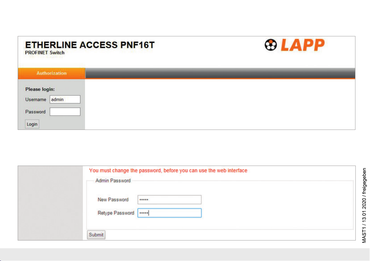
9. Diagnosis and configuration via the web interface
The web interface is also accessible under the IP address assigned to the PROFINET switch in the PROFINET network.
When the web interface is first called up, the password of the “admin” user is the serial number of the device. The serial number is indicated on the right housing side part (e.g. “50001234”).
It is absolutely necessary to assign a new password following the first login:
Quick Start Guide PROFINET switch 4/8/16 port10

One goes to the system view following entry of the new password:
Note: If the PROFINET switch is configured and used in a PROFINET network, settings in the web interface are only to be viewed as a diagnosis.
A reconfiguration of PROFINET-related settings (Port Status, LLDP, DCP, Ring Redundancy) is then not possible in the web interface.
Quick Start Guide PROFINET switch 4/8/16 port 11

10. Switch diagnosis and settings
Extensive information and settings for the function of the switch are accessible in the Switch menu.
11. Port mirroring
In order to be able to carry out frame analyses or recordings, Port Mirroring can be activated in the PROFINET switch. With Port Mirroring, the frame transfer from one
“mirrored port” to the “Monitor Port” is completely mirrored, on which an analysis PC can then record everything.
Quick Start Guide PROFINET switch 4/8/16 port12

12. Statistics
Detailed statistics on the data transfer can be queried in the “Statistics” menu.
Among other things, the quality of the transmission can be monitored in the sub-menu “Statistics by Error”.
Quick Start Guide PROFINET switch 4/8/16 port 13

13. Agents
In order to already be able to view basic information about the switch at the start website, before or without having logged in, the option “System Status Without Login” can be selected.
With “Web Session Timeout”, it can be established whether an automatic logout should take place in the event of inactivity at the website for security reasons.
Quick Start Guide PROFINET switch 4/8/16 port14

14. SNMP
The PROFINET switch supports SNMP (“Simple Network Management Protocol”) in order to also enable the identification and diagnosis of the switch for IT administration tools.
Quick Start Guide PROFINET switch 4/8/16 port 15

15. Setting the time
The PROFINET switch contains a system clock for the issuing of logs and alarm messages. This can be set either manually or automatically by an SNTP server.
Quick Start Guide PROFINET switch 4/8/16 port16

16. Resetting to factory settings
In order to reset the PROFINET switch to the delivery status, the function “Factory Reset” can be used in the web interface under “System” g “Restart”.
Alternatively, the PROFINET switch can be reset by pressing and holding the “FCN” button while the device restarts. A restar t can be carried out by switching the power supply off and on or by
activating the RST button.
The successful resetting of the parameters and settings is acknowledged during the boot process by the SF LED lighting up together with the PWR LED.
17. Firmware update
A firmware update can be carried out via the web interface.
The firmware update file can be selected in the menu “System g Firmware”.
The file has the ending “HUF”.
The firmware is transferred to the PROFINET switch and burned with the
“Send” button.
The new firmware is active following a restart of the PROFINET switch.
Important: Switching off the power supply during the update process can make
the device unusable.
Please download t
or scan the QR code.
he
firmware update file under www.lappkabel.com/activenetworkcomponents
SCAN
QR CODE
TO GET
FIRMWARE
Quick Start Guide PROFINET switch 4/8/16 port 17

18. LED status information
PWR
Off No power supply or device defective
On Device is correctly supplied with voltage
RUN
Flashing light The device starts
On The device is ready to operate
BF
On The device has no configuration and/or there is no
connection with the PROFINET controller
SF
On A PROFINET diagnosis is available
RJ45 LEDs
Green (Link) Connected
Orange (Act) Data transfer at the network
Note: The LEDs “RUN”, “BF”, and “SF” all flash synchronously when the PROFINET function
for device identification has been activated.
19. Button functions
FCN
RST
The PROFINET switch can be reset to factory settings with the
“FCN” button.
If the “FCN” button is pressed during the run-up time of the
switch, the orange “SF” LED begins to flash. The blinking
indicates that the switch will be immediately reset to factory
settings and restarted as soon as the switch is released.
The run-up phase is indicated by the blinking of the “RUN”
LED.
The “RST” button triggers an immediate restart of
the PROFINET switch, in the course of which all saved settings
are retained.
Quick Start Guide PROFINET switch 4/8/16 port18

20. Technical data
Dimensions (D x W x H)
Weight
PROFINET ports
- Protocol
- Physical layer
- Transmission rate
- Connection
- Features
Status indicator
Voltage supply
Current draw
Power dissipation
Permissible ambient temperature
Transport and storage temperature
Protection rating
Certifications
UL
- Voltage supply
- Pollution degree
- Altitude
- Temperature cable rating
PROFINET switch, 4 port, managed
ETHERLINE
32 x 59 x 76mm 32 x 82 x 76mm 32 x 146 x 76mm
Approx. 130g Approx. 180g Approx. 310g
PROFINET IO as defined in IEC 61158-6-10 PROFINET IO as defined in IEC 61158-6-10 PROFINET IO as defined in IEC 61158-6-10
Ethernet Ethernet Ethernet
100 Mbps, full duplex 100 Mbps, full duplex 100 Mbps, full duplex
4 x RJ45, integrated switch 8 x RJ45, integrated switch 16 x RJ45, integrated switch
Media Redundancy Protocol (MRP)
Automatic addressing/
Topology recognition (LLDP, DCP)
4 LEDs function status,
8 LEDs Ethernet status
DC 24 V (18 ... 30 V DC) DC 24 V (18 ... 30 V DC) DC 24 V (18 ... 30 V DC)
Max. 250 mA at 24 V DC Max. 350 mA at 24 V DC Max. 290 mA at 24 V DC
Max. 2.4 W Max. 2 W Max. 5.5 W
-40°C … +75°C -40°C … +75°C 0°C ... +60°C
-40°C … +85°C -40°C … +85°C -40°C ... +85°C
IP 20 IP 20 IP 20
CE, UL CE, UL CE, UL
UL 61010-1/ UL 61010-2-201 UL 61010-1/ UL 61010-2-201 UL 61010-1/ UL 61010-2-201
24 V DC
circuit)
2 2 2
Up to 2,000 m Up to 2,000 m Up to 2,000 m
87°C 87°C 87°C
®
ACCESS PNF04T
(18 ... 30 V DC, SELV and limited energy
PROFINET switch, 8 port, managed
ETHERLINE® ACCESS PNF08T
Media Redundancy Protocol (MRP)
Automatic addressing/
Topology recognition (LLDP, DCP)
4 LEDs function status,
16 LEDs Ethernet status
24 V DC
(18 ... 30 V DC, SELV and limited energy
circuit)
PROFINET switch, 16 port, managed
ETHERLINE® ACCESS PNF16T
Media Redundancy Protocol (MRP)
Automatic addressing/
Topology recognition (LLDP, DCP)
4 LEDs function status,
32 LEDs Ethernet status
24 V DC
(18 ... 30 V DC, SELV and limited energy
circuit)
Quick Start Guide PROFINET switch 4/8/16 port 19

Note:
The contents of this Quick Start Guide have been checked by us so as to ensure that they match the hardware and software described.
However, we assume no liability for any existing differences, as these cannot be fully ruled out.
The information in this Quick Start Guide is, however, updated on a regular basis. When using your purchased products, please make sure to use the latest version of this Quick Start Guide,
which can be viewed and downloaded on the Internet from www.lappkabel.com/activenetworkcomponents.
Our products contain open source software, among others. This software is subject to the respectively relevant license conditions. We can send you the corresponding license conditions,
including a copy of the complete license text together with the product. They are also provided in our download area of the respective products under
www.lappkabel.com/activenetworkcomponents.
We also offer to send you or any third party the complete corresponding source text of the respective open source software for an at-cost fee of 10.00 Euro as a DVD upon request.
This offer is valid for a period of three years, starting from the date of product delivery.
1)
SIMATIC is a registered trademark of Siemens AG.
Our customers are at the center of everything we do. We welcome all ideas and suggestions.
U.I. Lapp GmbH | Schulze-Delitzsch-Straße 25 | 70565 Stuttgart | Germany | Phone: +49 (0)711-7838-01 | Fax: +49 (0)711-7838-2640 | info@lappkabel.de | www.lappkabel.com
 Loading...