

Laplante V120103-RS11 Operation Manual
Operation manual
OPERATION MANUAL
MODEL: V120103-RS11
Rotary Screw Stationary
Air Compressor
7502 Mesa Road Houston, TX77028
Telephone: (713) 635-6331
E-mail: service@lapante.com
Web Site: www.laplantecompressor.com
- 1 -

Operation manual
GENERAL INFORMATION:
This compressor is for compressing atmospheric air and is not suitable for compressing any
other gas. It is designed and manufactured to give optimum performance with long life and
reliability.
The manual gives the user all the information required to install and operate the compressor
and carry out the regular schedules for servicing and maintenance, which ensure the maximum
satisfactory service life.
LAPLANTE WARRANTY
Please refer to the attached LaPlante Compressor LTD. “Warranty Manual” for full details of
the LPRS Express Warranty versus the Extended Air End Warranty options that are
available for 3 and 5 year terms, plus LaPlante’s lines of Proprietary Lubricants. The
Warranty Manual also provides details of the LaPlante Oil Monitoring and Oil Sampling
Program.
The LaPlante Extended Air End Warranty applies to only the LPRS COMPRESSORS that
are operating exclusively with LaPlante Proprietary Lubricants.
Note: Unauthorized disassembly or repair of LaPlante Air end in the field will void the
warranty and adversely affect the trade-in value.
- 2 -

Operation manual
CONTENTS
1.0 SAFETY PRECAUTIONS
1.1 Safety Precautions During Installation
1.2 Safety Precautions During Installation
1.3 Safety Precautions During Maintenance and Repair
1.4 Symbols and Warnings
2.0. INSTALLATION
2.1 Compressor Dimensions Drawing
2.2 Mounting & space requirements
2.3 Guidelines for Compressor Air System
2.4 Unpacking and Handle
2.5 Storage
2.6 Installation Drawings (Recommended)
3.0 SPECIFICATION - GENERAL
3.1 Compressor Specification Sheet
3.2 Lubrication Specification
3.3 Electric specification sheet
4.0. CONTROLLER
4.1 Introduction
4.2 Controller Panel
4.3 Symbol Meaning
4.4 Start and Loading
4.5 Stop
4.5.1 Manual Stop
4.5.2 Un-loading Stop
4.5.3 Emergency Stop
4.5.4 Malfunction Stop
4.6 Warning
4.7 Calling Up the Display
4.8 Change the Timer
4.9 Programmable Settings
4.10 Terminology
5.0: OPERATION
5.1 Before Initial Start-up
5.2 Initial Start-up
5.3 Starting
5.4 During Operation
5.5 Checking the Display
5.6 Stopping
5.7 Taking Out of Operation
- 3 -

Operation manual
6.0: COMPRESSOR SYSTEM & FUNTIONAL COMPONENTS
6.1 Introduction
6.2 Air End
6.3 Air Flow System
6.3.1 Air Filter and Inlet Valve
6.3.2 Air/Oil Separator
6.3.3 Minimum Pressure Check Valve
6.4 Oil System
6.4.1 Oil Cooler
6.4.2 Oil Filter
6.4.3 Thermal Mixing Valve
6.5 Electric System and Components
6.6 Modulation System
6.7 Safety System
7.0: PREVENTATIVE MAINTENANCE
7.1 Preventative Maintenance
7.2 Oil Testing
7.3 Oil Replacement
7.4 Oil Filter Replacement
7.5 Air Filter Replacement
7.6 V-belts Replacement
7.7 Electrical Motor
7.8 Fan
7.9 Minimum Pressure/Check Valve
7.10 General Maintenance and Clearings
8.0: TROUBLESHOOTING TABLE
9.0: PARTS LIST
9.1 LPRS11-230V, the P/N of LaPlante is 001117
9.2 LPRS11-575, the P/N of LaPlante is 001118
10.0: MAIN WEARABLE PARTS LIST
- 4 -

Operation manual
1.0: SAFETY PRECAUTIONS
FOREWORD
This manual contains vital information for the safe use and efficient operation of this unit. It
must be read carefully and understood before installing, operating or servicing. Otherwise,
personnel are exposed to the risk of serious injury or death.
The operator should use common sense and good working practices while operating and
maintaining this unit. Follow all codes, pipe adequately, and understand the starting and
stopping sequence. Check the safety devices & following the procedures contained in this
manual.
Maintenance should be done be qualified personnel, adequately equipped with proper tools.
Follow the maintenance schedules as outlined in the manual to ensure problem free operation
after start up.
1.1 Safety Precautions During Installation:
General Precaution:
1. The operator must employ safe working practices and observe all related local work safety
requirements and regulations.
2. If any of the following statements does not comply with local legislation, the stricter of the
two shall apply.
3. Installation, operation, maintenance and repair work must only be performed by authorized,
trained, specialized personnel.
4. The compressor is not considered capable of producing of breathing quality. For air of
breathing quality, the compressed air must be adequately purified according to local
legislation and standards.
5. Before any maintenance, repair work, adjustment or any other non-routine check, stop the
compressor, press the emergency stop button, switch off the voltage and depressurize the
compressor. In addition, the power isolating switch must be opened and locked.
6. Never play with compressed air. Do not apply the air to your skin or direct an air stream at
people. Never use the air to clean dirt from your clothes. When using the air to clean
equipment, do so with extreme caution and wear eye protection.
All responsibility for any damage or injury resulting from neglecting these
precautions, or non-observance of the normal caution and care required for
installation, operation, maintenance and repair, even if not expressly stated,
will be disclaimed by the manufacturer.
Precautions during Installation:
1. The machine must only be lifted using suitable equipment in accordance with local safety
regulations. Loose or pivoting parts must be securely fastened before lifting. It is strictly
forbidden to dwell or stay in the risk zone under a lifted load. Lifting acceleration and
deceleration must be kept within safe limits. Wear a safety helmet when working in the area
of overhead or lifting equipment.
2. Place the machine where the ambient air is as cool and clean as possible. If necessary,
install a suction duct. Never obstruct the air inlet. Care must be taken to minimize the entry
- 5 -

Operation manual
of moisture at the inlet air.
3. Any blanking flanges, plugs, caps and desiccant bags must be removed before connecting
the pipe.
4. Air hoses must be of correct size and suitable for the working pressure. Never use frayed,
damaged or worn hose. Distribution pipes and connections must be of the correct sixe and
suitable for the working pressure.
5. The aspirated air must be free of flammable fumes, vapours and particles, e.g. paint
solvents, that can lead to internal fire or explosion.
7. Ensure that the discharge pipe from the compressor to the aftercooler or air net is free to
expand under heat and that it is not in contact with or close to flammable materials.
8. No external force may be exerted on the air outlet valve, the connected pipe must be free of
strain.
9. If remote control is installed, the machine must bear a clear sign stating: DANGER: This
machine is remotely controlled and may start without warning.
The operator has to make sure that the machine is stopped and that the isolating switch is
open and locked before any maintenance or repair. As a further safeguard, persons
switching on remotely controlled machines shall take adequate precautions to ensure that
there is no one checking or working on the machine. To this end, a suitable notice shall be
affixed to the start equipment.
10. Air-cooled machines must be installed in such a way that an adequate flow of cooling air is
available and that the exhausted air does not recirculate to the compressor air inlet or
cooling air inlet.
11. The electrical connections must correspond to the local codes. The machines must be
earthed and protected against short circuits by fuses in all phases. A lockable power
isolating switch must be installed near the compressor.
12. On machines with automatic start-up system or if the automatic restart function after
voltage failure is activated, a sign stating” This machine may start without warning” must
be affixed near the instrument panel.
13. In multiple compressor system, Manual valves must be installed to isolated each
compressor. Non-return valves( check valves) must not be relied upon for isolating
pressure system.
14. Never remove or tamper with the safety devices, guards or insulation fitted on the machine.
Every pressure vessel or auxiliary installed outside the machine to contain air above
atmospheric pressure must be protected by a pressure- relieving device or device as
required.
15. Pipe work or other parts with a temperature in excess of 80 degree C (176 degree F) and
which may be accidentally touched by personnel in normal operation must be guarded or
isolated. Other high-temperature pipework must be clearly marked.
16. For water-cooled machine, the cooling water system installed outside the machine has to
be protected by a safety device with set pressure according to the maximum cooling water
inlet pressure.
17. If the ground is not level or can be subject to variable inclination, consult the manufacturer.
Also consult following safety precautions; Safety precautions during
operation and safety precautions during maintenance.
These precautions apply to machinery processing or consuming air or inlet
gas.
Processing of any other gas requires additional safety precautions typical
to the application which are not included herein.
Some precautions are general and cover several machine types and
equipment, hence some statements may not apply to your machine.
- 6 -

Operation manual
1.2 Safety Precautions during Operation:
General Precautions:
1. The operator must employ safe working practices and observe all related local work safety
requirements and regulations.
2. If any of the following statements does not comply with local legislation, the stricter of the
two shall apply.
3. Installation, operation, maintenance and repair work must only be performed by authorized,
trained, specialized personnel.
4. The compressor is not considered capable of producing air of breathing quality. For air of
breathing quality, the compressed air must be adequately purified according to local
legislation and standards.
5. Before any maintenance, repair work, adjustment or any other non-routine checks, stop the
compressor, press the emergency stop button, switch off the voltage and depressurize the
compressor, in addition, the power isolating switch must be opened and locked.
6. Never play with compressed air. Do not apply the air to your skin or direct an air stream at
people. Never use the air to clean dirt from your clothes. When using the air to clean
equipment, do so with extreme caution and wear eye protection.
All responsibility for any damage or injury resulting from neglecting these
precautions, or non-observance of the normal caution and care required for
installation, operation, maintenance and repair, even if not expressly stated,
will be disclaimed by the manufacturer.
PRECAUTIONS DURING OPERATION:
1. Use only the correct type and size of hose end fittings and connections. When blowing
through a hose or air line, ensure that the open end is held securely. A free end will whip and
may cause injury or death. Make sure that a hose is fully depressurized before disconnecting
it.
2. Persons switching on remotely controlled machines shall take adequate precautions to
ensure that there is no one checking or working on the machine. TO this end, a suitable
notice shall be affixed to the remote start equipment.
3. Never operate the machine when there is a possibility of taking in flammable or toxic fumes,
vapour or particles.
4. Never operate the machine below or in excess of its limit ratings.
5. Keep all bodywork doors shut during operation. The doors may be opened for short periods
only, E.G.. to carry out routine checks. Wear ear protectors when open a door.
6. People staying in environments or room s where the sound pressure level reaches or
exceed 90 Db(A) shall wear ear protectors.
7. Periodically check that:
1) All guards are in place and securely fastened
2) All hoses and/or pipes inside the machine are in good condition, secure and not rubbing.
3) There are no leaks
4) All fasteners are tight
5) All electrical leads are secure and in good order
6) Safety valves and other pressure-relief device are not obstructed by dirt or paint.
7) Air outlet valve and air net, i.e. pipe, coupling, manifolds, valves, hosed, etc. are in good
repair, free of wear or abuse.
8. If warm cooling air from compressors is used in air heating system, e.g. to warm up a
- 7 -
Operation manual
workroom, take precautions against air pollution and possible contaminations of the
breathing air.
9. Do not remove any of, or tamper with, the sound-damping material.
10. Never remove or tamper with the safety devices, guards or insulations fitted on the
machine. Every pressure vessel or auxiliary installed outside the machine to contain air
above atmospheric pressure vessel or auxiliary installed outside the machine to contain air
above atmospheric pressure shall be protected by a pressure-relieving device or devices as
required.
Also consult following safety precautions; Safety precautions during
operation and safety precautions during maintenance.
These precautions apply to machinery processing or consuming air or inlet
gas.
Processing of any other gas requires additional safety precautions typical
to the application which are not included herein.
Some precautions are general and cover several machine types and
equipment, hence some statements may not apply to your machine.
1.3 Safety Precautions during Maintenance or Repair:
GENERAL PRECASTIONS
1. The operator must employ safe working practices and observe all related local work safety
requirements and regulations.
2. If any of he following statements does not comply with local legislation, the stricter of the two
shall apply.
3. Installation, operation, maintenance and repair work must only be performed by authorized,
trained, specialized personnel.
4. The compressor is not considered capable of producing air other non-routing check, stop the
compressor, press the emergency stop button, switch off the voltage and depressurize the
compressor, in addition, the power isolating switch must be opened and locked.
5. Before any maintenance, repair work, adjustment or any other non-routine checks, stop the
compressor, press the emergency stop button, switch off the voltage and depressurize the
compressor. In addition, the power isolating switch must be opened and locked.
6. Never play with compressed air. Do not apply the air to your skin or direct an air stream at
people. Never use the air to clean dirt from your clothes. When using the air to clean
equipment, do so with extreme caution and wear eye protection.
All responsibility for any damage or injury resulting from neglecting these
precautions, or non-observance of the normal caution and care required for
installation, operation, maintenance and repair, even if not expressly stated,
will be disclaimed by the manufacturer.
PRECAUTIONS DURING MAINTENANCE OR REPAIR
1. Always wear safety glasses.
2. Use only the correct tools for maintenance and repair work.
3. Use only genuine spare parts.
4. All maintenance work shall only be undertaken when the machine has cooled down.
5. A warning sign bearing a legend such as “ work in progress; do not start” shall be attached
- 8 -

Operation manual
to the starting equipment.
6. Persons switching on remotely controlled machines shall take adequate precautions to
ensure that there is no one checking or working on the machine. To this end, a suitable
notice shall be affixed to the remote start equipment.
7. Close the compressor air outlet valve before connecting or disconnecting a pipe.
8. Before removing any pressurized component, effectively isolate the machine from all
sources of pressure and relieve the entire system of pressure.
9. Never use flammable solvents or carbon tetrachloride for cleaning parts. Take safety
precautions against toxic vapours of cleaning liquids.
10. Scrupulously observe cleanliness during maintenance and repair. Keep dirt away by
covering the parts and exposed openings with a clean cloth, paper or tape.
11. Never weld or perform any operation involving heat near the oil system. Oil tanks must be
completely purged, e.g. by steam-cleaning, before carrying out such operations. Never
weld on , or in any way modify, pressure vessels.
12. Whenever there is an indication or any suspicion that a internal part of machine is
overheated, the machine shall be stopped but no inspection covers shall be opened before
sufficient cooling time has elapsed; this to avoid the risk of spontaneous ignition of the oil
vapour when air is admitted.
13. Never use a light source with open flame for inspecting the interior of a machine, pressure
vessel, etc.
14. Make sure that no tools, loose parts or rags are left in or on the machine.
15. All regulating and safety devices shall be maintained with due care to ensure that their
function properly. They may not be put out of action.
16. Before clearing the machine for use after maintenance or overhaul, check that operating
pressures, temperatures and time setting are correct. Check that all control and shut-down
devices are fitted and that their function correctly. If removed, check that the coupling guard
of the compressor drive shaft has been reinstalled.
17. Every time the separator element is renewed, examine the discharge pipe and the inside of
the oil separator vessel for carton deposits; if excessive, the deposits should be removed.
18. Protect the motor, air filter, electrical and regulating components, etc. to prevent moisture
from entering them, e.g. when steam-cleaning.
19. Make sure that all sound-damping material, e.g. on the bodywork and in air inlet and outlet
systems of the compressor, is in good condition. If damaged, replace it by genuine material
from the manufacturer to prevent the sound pressure level from increasing.
20. Never use caustic solvents which can damage material of the air net e.g. polycarbonate
bowls.
21. The following safety precautions are stressed when handling refrigerant:
1) Never inhale refrigerant vapours. Check that the working area is adequately ventilated; if
required, use breathing protection.
2) Always wear special gloves. In case of refrigerant contact with the skin, rinse the skin
with water. If liquid refrigerant contacts the skin through clothing until, all refrigerant is
flushed away; then seek medical first aid.
22. Protect hands to avoid injury from hot machine parts, e.g. during draining of oil.
Also consult following safety precautions; Safety precautions during
operation and safety precautions during maintenance.
These precautions apply to machinery processing or consuming air or inlet
gas.
Processing of any other gas requires additional safety precautions typical
to the application which are not included herein.
Some precautions are general and cover several machine types and
- 9 -
Operation manual
equipment, hence some statements may not apply to your machine
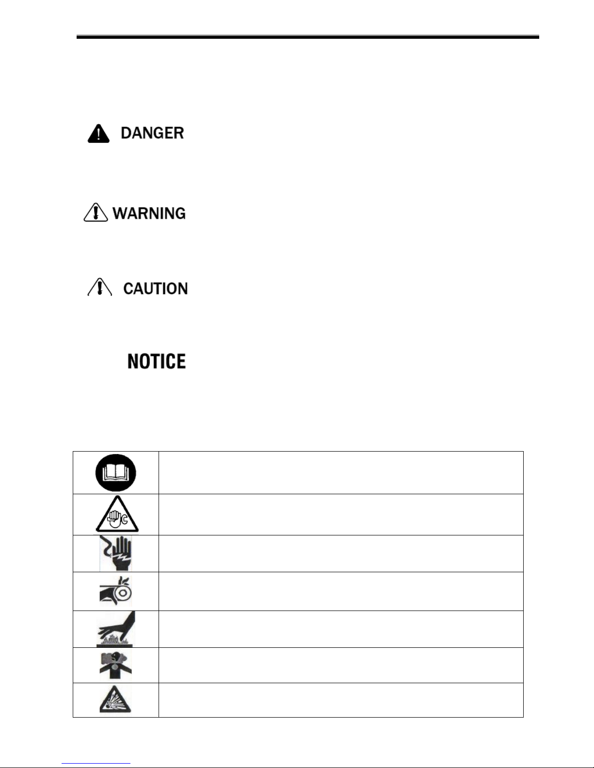
Throughout the manual various safety concerns will be brought to your attention with boxes
containing one of the following notations:
Danger is used to indicate the presence of a hazard, which will cause
severe personal injury, death or substantial equipment and property
damage if the warning is ignored.
Warning is used to indicate the presence of a hazard that can cause
severe personal injury, death or substantial equipment and property
damage if the warning is ignored.
Caution is used to indicate the presence of a hazard that will or can
cause personal injury or equipment and property damage if the
warning is ignored.
Notice is used to notify people of installation, operation, or
maintenance of information that is important but not hazard related.
1.4 Symbols and Warnings
An adhesive label, visibly placed on the cover of the compressor, reports a series of symbols
(pictograms) to inform anyone about risks and residual dangers contained in the compressor
itself.
Obligatory to Read Instruction Manual
Danger: Maintenance Work(Consult Instruction Manual)
Danger: High Voltage. Disconnect Power Source before servicing
Forbidden TO Remove Protective Covering And Safety Devices
Danger: Heat. Do Not Touch Hot Areas
Danger: Hot or Noxious Gases Outlet: Unbreathable
Danger: Relief Tank Pressure before Servicing
- 10 -

Operation manual
Rotation In Direction Of Arrow
Emergency Stop Switch
Stop Switch
Start-up Switch
- 11 -
Operation manual
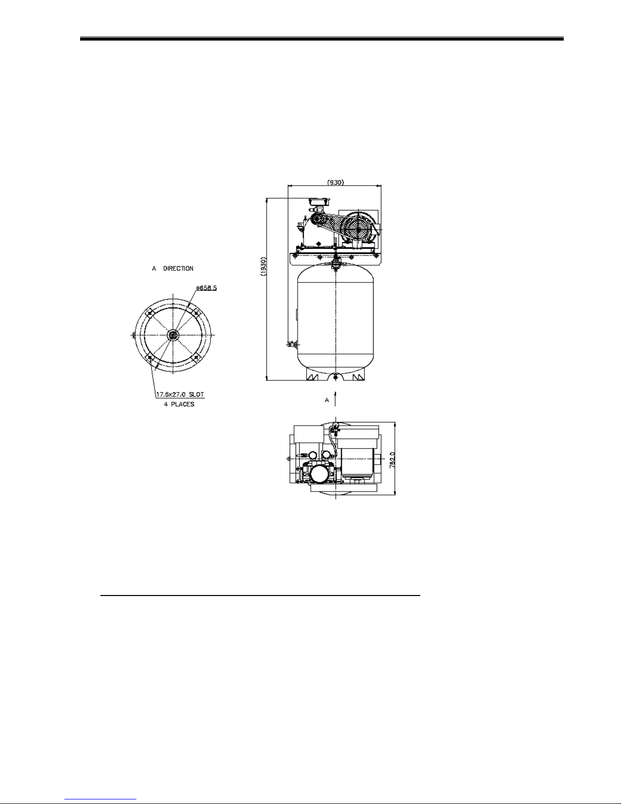
2.0: INSTALLATION
2.1 Compressor Dimensions Drawing:
2.2 Mounting and Space Requirement:
The LPRS series is designed for indoor applications only. Allow at lease three (3) feet
clearance on all sides of the compressor to facilitate maintenance as well as free circulation of
air. Unit should be located in a clear, well-lighted area that will not have an ambient air
temperature below 40 degree F or exceed 105 degree F. Provisions must be made for proper
ventilation so that the temperature of the room will not exceed 105 degree F.
Foundation:
Your LaPlante’s rotary screw compressor does not require a special foundation. However, it is
necessary that the floor is level and the frame adequately supported. Consult the
“Specifications” section of this manual for the compressor weight and dimensions. We do
recommend that the compressor be bolted to the floor.
Room:
- 12 -
Operation manual
The room should be of adequate size to provide full access to the machine for routine
maintenance. It should have ventilation to keep the room as cool as possible. It is
recommended that the air handling system be designed to permit no more than a 10 degree F
rise in room temperature. Operating at elevated temperatures will cause nuisance overload,
temperature shutdowns and reduces oil life. The recommended minimum room air flow is
Approx.1500CFM.
Air Intake:
Air supplied to the compressor should be free of contaminants such as paint spray mist and
vapors, other chemical vapors as well as normally air bone dust and dirt particles.
Inlet air to the unit may vary slightly in temperature without adversely affecting the performance
of the compressor. However, ambient air temperature should be maintained between 32 deg. F
and 104 deg. F to obtain desirable performance.
The air filter supplied with the compressor has an adequate flow capacity for most applications.
In particular dirty locations, clean air may be ducted in from a clean air source or special air
cleaners may be installed. Generally, most adverse conditions may be overcome by regular
servicing of the filter furnished with the unit.
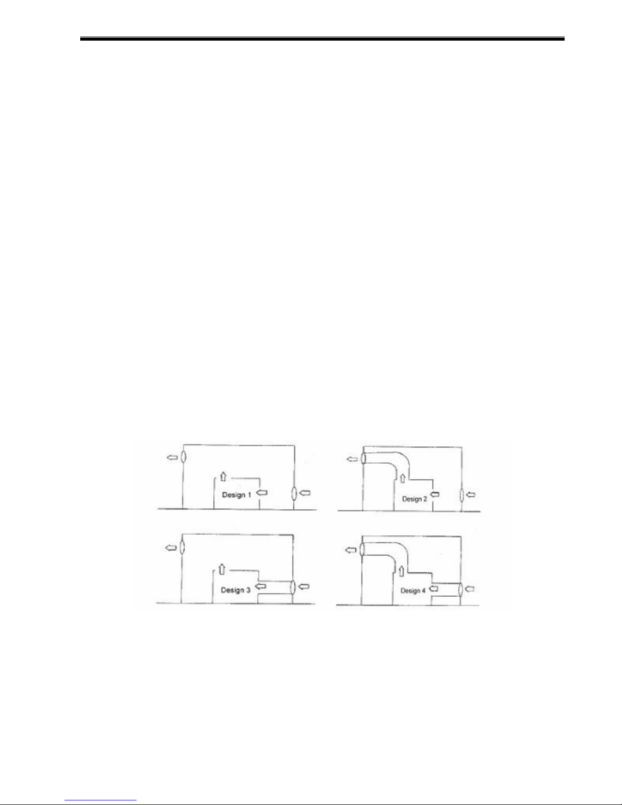
When bringing in outside air into the compressor building for cooling and/or compression, the
air inlet to the compressor building should be located away from contaminants such as engines
exhaust gases, steam and other harmful vapors.
Also, the opening to the building must be protected from rain, snow and other air-borne debris
by cover or hood, as well as being located above the ground/roof to prevent other foreign
matter pick-up. For a typical ducting arrangement refer to (figure 2-1)
Figure 2-1 Typical Ducting Arrangement
Both inlet and outlet ducts must be sized so that they are restriction free. Where ambient
temperatures are below 32 deg. F (Inlet air), entering the compressor’s air temperature can be
raised by controlled re-circulation. This may be accomplished by using adjustable louvers (or
duct dampers) to admit warm air from the outlet duct back into the inlet duct at a controlled rate.
If duct filters are used, the filters must be restriction free. Typical furnace filter material may be
used.
The inlet grids and ventilation fan should be installed in such a way that any recirculation of
cooling air to the compressor is avoided. the maximum air velocity through the grids is 16.6
- 13 -
Operation manual
ft/s .
Inlet containing reactive gases will cause the failure of the lubricant and
compressor.
Insure an air supply that is well clear of any reactive gas source.
Air Supply to Compressor (Cooling and Compression):
The cooling air discharge must be restriction free. Any louvers or ducting must not exceed the
allowed static head shown in the specifications. Above this booster fan will be required.
Consult a local HVAC contractor for recommendations prior to installation. Excessive
restriction to the cooling air discharge will cause the unit to operate at elevated temperatures
that could result in high temperature shutdowns. Ducting of cooling air to the unit is not
generally recommended.
Inadequate airflow will cause the compressor to run hot, can damage the
compressor, and increase the amount of oil carryover.
The room temperature should not raise motor than 10 degree F and the
cooling air discharge must not be restricted.
Electrical:
A qualified electrician in compliance with standards and local codes should do all electrical
wiring. Be sure to investigate the local requirements before installing the compressor.
The power supply should be adequate and free of parasitic loads that will cause an under
voltage condition during the operation of the compressor, otherwise there will be nuisance
electrical shutdowns. Though the unit has a disconnect, we recommend that one be installed
away from the machine and insure the unit is properly grounded.
We recommend the use of time delay fuses in fusible disconnect for isolating the unit. This
disconnect should be located so an operator can disconnect the unit without nearing the unit,
in case of an emergency. We also recommend the use of a lockout/tag out program to help
insure safety during maintenance of the compressor. Per the national Electric Code the time
delay fuses should be sized at 175% if the FLA. Consult the code if you want to use another
style of branch circuit protection.
In all cases, the local, state, and national electrical codes must be strictly
followed.
All control enclosure wiring has been completed at the factory. Connect the wire steps are
as follow:
A. Open the power cabinet door
B. Check that the motor cables and wires are clamped tightly to their terminals.
- 14 -
Operation manual
C. Check the fuses and the setting of the overload.
D. Connect the power supply to the terminals the L1, L2, L3.
E. Connect the earth conductor bolt.
For choice the cable please reference table 3-2 of the electrical specification sheet.
2.3 Guidelines for Compressor Air System:
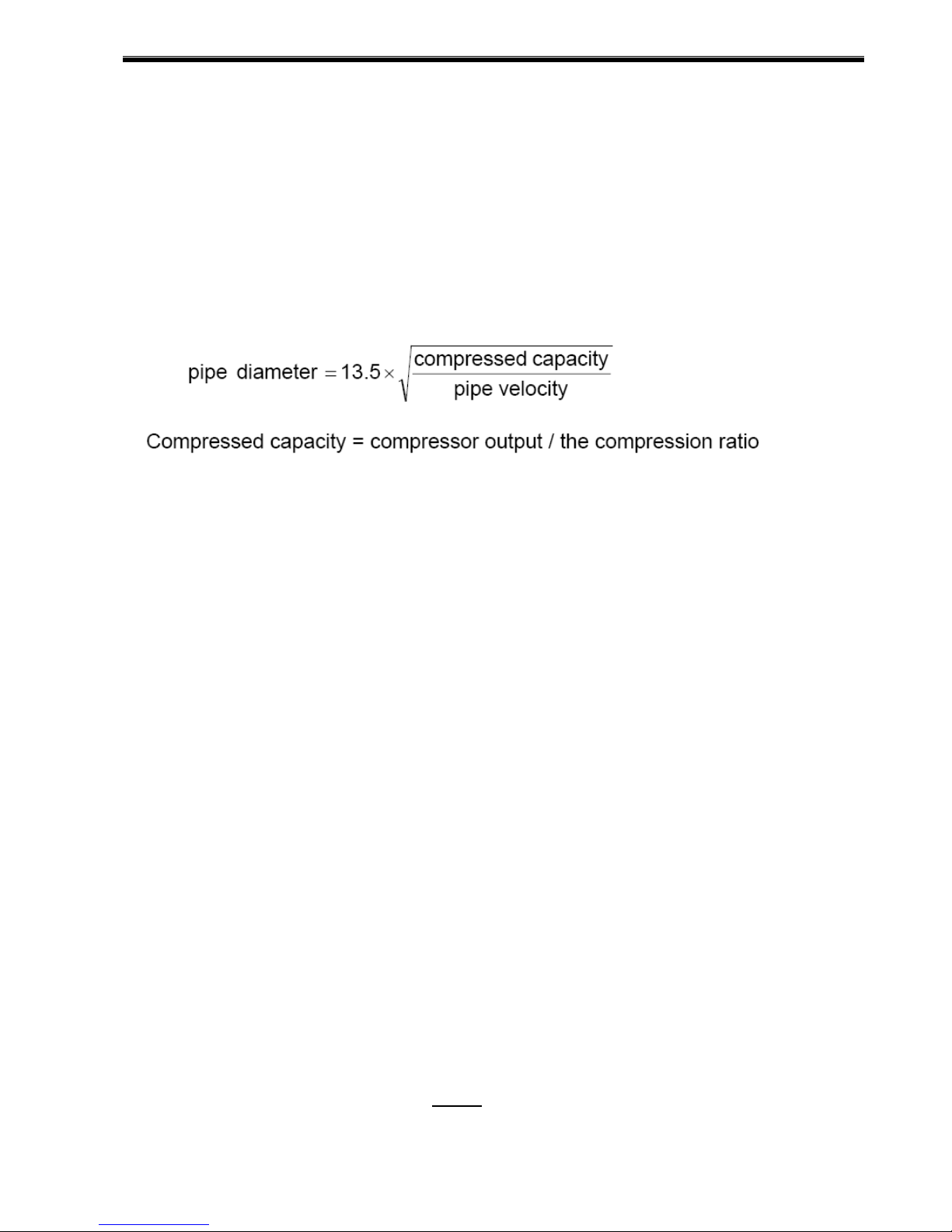
· The air pressure drop between the compressor and the point of use is not recoverable.
· Pipe Size should be large enough that the pressure drop does not exceed 10% between
the air receiver and the point of use. Generally keep the compressed flow at around 1500 –
2250 feet/minute velocity.
· Arrange the air distribution pipe to avoid the following types off strains:
1. Strains that is due to the dead weight if the pipe itself.
2. Strains that is due to expansion or contraction of the pipe due to temperature.
3. Strains due to internal pressure within the pipe.
· Design inlet and discharge piping for smooth airflow.
· Plan for future emergencies and establish an area of the loop to install a temporary
compressor.
· Consider bypass lines around all items that may require future maintenance.
· Use loop-pipe systems if possible, both around the plant and within wore areas.
· Consider a second receiver at the end of the line or opposite side of the loop.
· Locate runs away from the main header close to the point of application. This limits the
pressure drop through hose.
· Take air off the top of the header to prevent carryover of condensed moisture to tools.
· Slope pipe so that it drains toward a drop let or moisture trap away from the compressor.
2.4 Unpacking and Handling:
Occasionally damage will occur during shipping. Be sure to carefully inspect the unit before
unpacking and after unpacking before you sign the receiver. If any has occurred, document it
with the trucking firm immediately. Contact you LaPlante representative for assistance.
To move your compressor to its installation site, we recommend that you leave the unit on its
shipping skid as long as possible. The forks should be extended the width of the compressor
and padding should be placed between the compressor and the fork truck boom.
If it is necessary to lift the compressor with a crane, we recommend the use of spreader bar
and chains. The spreader bar should be greater than the width of the compressor and padding
placed on the edges to prevent chain damage.
Procedure for Handling Damaged Shipments:
1. The customer, at the receiving point, MUST inspect each shipment for damage.
2. If the shipment is damaged, the customer should so note it on the freight bill.
3. The customer should request an inspector from the freight company to inspect the equipment
- 15 -
Operation manual
immediately. It is best to send a confirming letter with the following information:
a. Freight bill number.
b. Date delivered - shipper's name & address.
c. Description of item(s) damaged.
d. Description of damage (a Polaroid picture if possible).
e. A copy of your invoice for the equipment.
4. After inspection, (before the inspector leaves):
a. Get a copy of the inspection report.
b. Request the unit be shipped back "free astray".
c. Request a credit for the original freight bill.
5. Call the factory and:
a. Get a Return Material Authorization (RMA number).
b. Give a purchase order for repair. The purchase order should refer to the item
and
trucker claim.
6. We will accept the shipment back, repair (under normal conditions) and return it within (7)
seven working days.
7. We will invoice the customer for the repair, which will then become part of your claim. The
invoice must be presented to the trucking claim department along with their claim form.
8. We suggest if the trucker does not pay within 30 days that you call and / or write the ICC
making a formal complaint of poor service. Also advise LaPlante Compressor Ltd. in
writing for follow-up.
If damage can be repaired at the receiving point, follow Procedure 1, steps 1 through
4a. Repair the unit and make out a detailed invoice to the trucker showing labor hours,
labor rate, materials used, and cost of materials.
2.5 Storage
In some cases it may necessary to store the compressor for extended periods of several
months before placing the unit in operation. When this is required do the following:
1. Cover and seal all machine openings to prevent the entrance of water and dirt.
2. Cover all openings in open drip proof motors to prevent the entrance of rodents.
3. If the storage conditions are below freezing, drain off the aftercooler, traps, water-cooled
heat exchangers and relative piping. We do not recommend outside storage.
4. Cover with a waterproof tarpaulin that can easily be removed for in storage maintenance.
5. While in storage, every two to three months rotate the compressor and motor by hand to
prevent flat spots on the bearings that will lead to premature failure.
At the end of the storage period, follow the uncrating and start-up procedures. If the unit has
been stored for more than eighteen months you should contact LaPlante Compressor Ltd.
before commissioning the compressor.
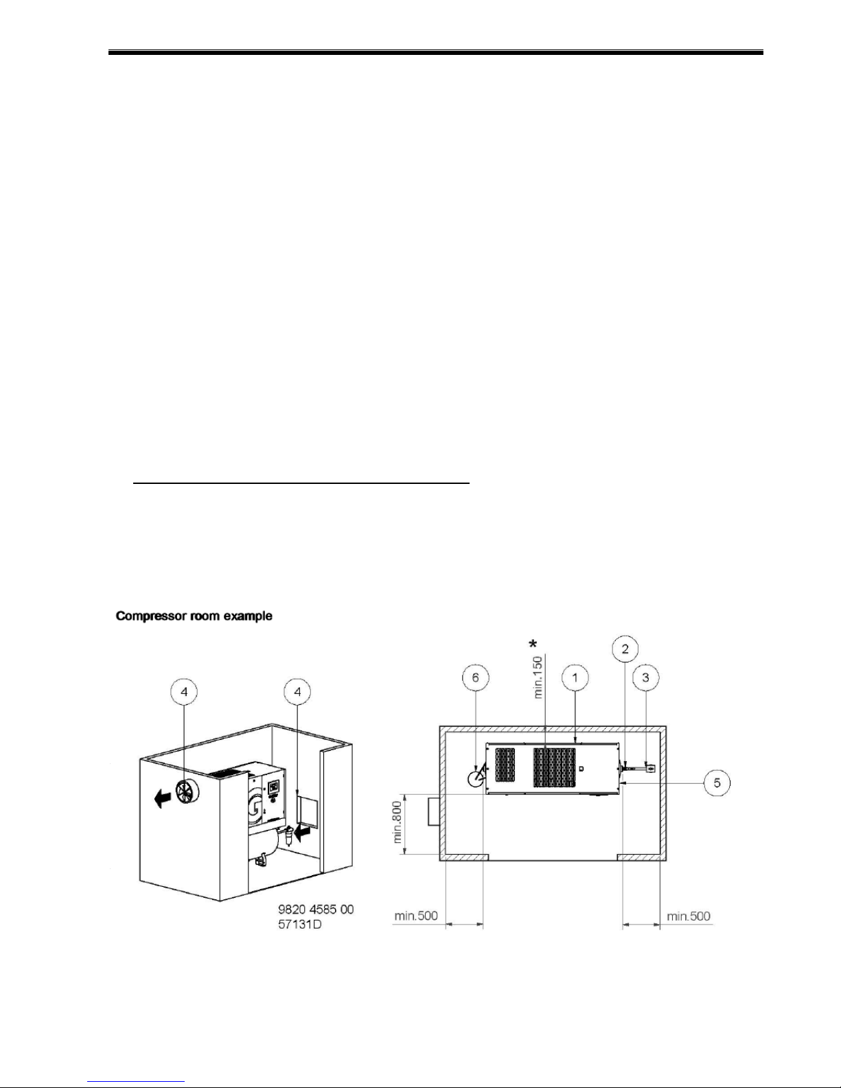
2.6 Installation Drawings (Recommended):
A minimum distance from walls, other machines, etc. should be maintained so that there is
sufficient clearance for maintenance and repair work ( refer to figure 2-2) .
We recommend a minimum duct cross-section of approx. 0.3 square meter. In order to ensure
a good heat dissipation, auxiliary fans should be rated to process approximately 15-20% more
air volume than the total cooling air quantity required by the compressors installed in the
compressed air station.
- 16 -
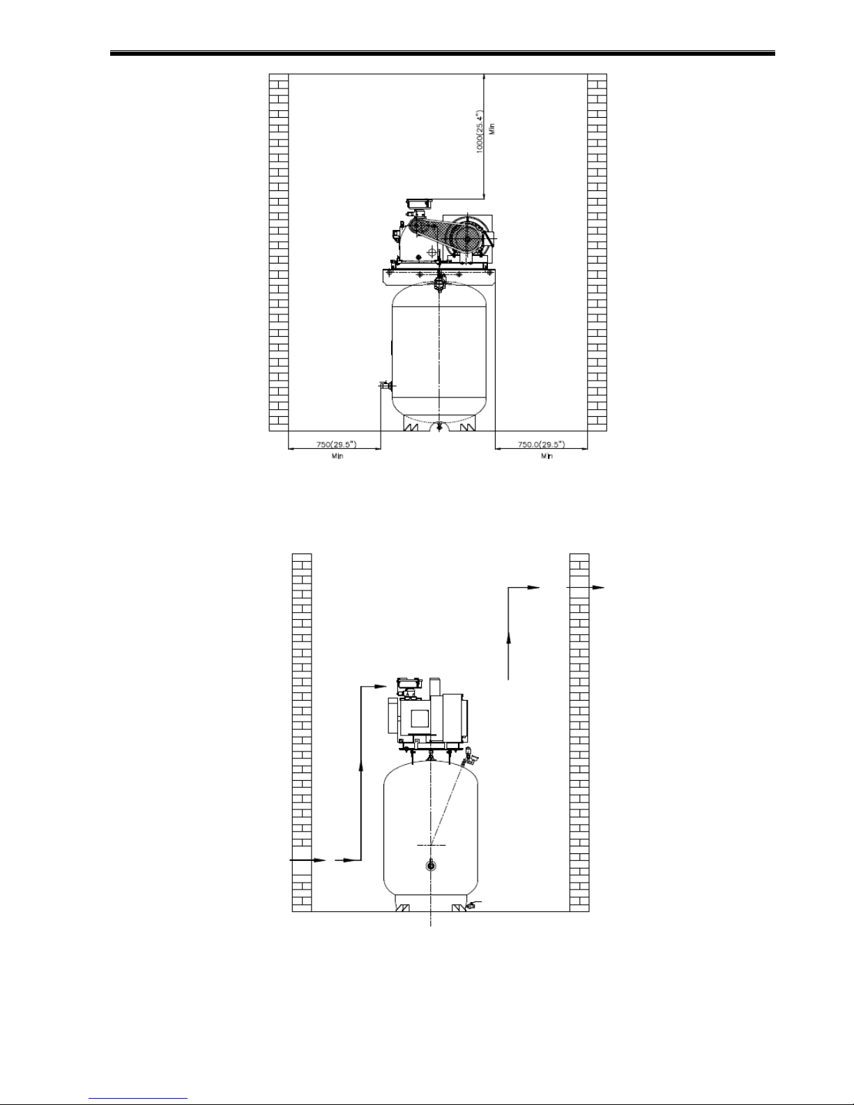
Operation manual
Figure 2-2 Installation Drawings
- 17 -
Operation manual
3.0: SPECIFICATION – GENERAL
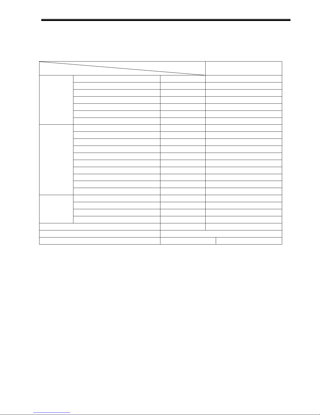
3.1 Compressor Specification Sheet :
Table 3-1 compressor specification
Model
Item
Cut-in Pressure Psig(Bar) 135(9.3)
Cut-out Pressure Psig(Bar) 150(10)
Volume Flow CFM(m3/min)
System
Motor
Dimension
NOTE:
3.2 Lubrication Specification
The useful life of compressor oil depends on the quality of the oil, the maintenance of the
Product and the condition in which the unit is operated.
Oil sampling and analysis is recommended every 200 hours of compressor operation at
least until an oil/oil filter change pattern or schedule is established. The quality of the oil is
left to the Oil Manufacturer. The responsibility for testing and evaluating the useful oil life is
left to the Oil Manufacturer and/or Compressor End User.
It is recommended that LaPlante Propriety Synthetic Lubricant be used.
LaPlante offers several types of Synthetic Lubricant conveniently packaged from your
nearest LaPlante Dealer.
Safety Valve(System) Setting Psig 164
Safety Valve(Network) Setting
Drive Type - Belt
Cooler Type - Air Cooled
Power HP/(KW) 10(7.5)
Enclosure Type TEFC(IP54)
Motor Frame - 215T
Main Motor Speed RPM 1750
Power Factory - 1.15
Ambient Temperature °C °F(°C) ≤104°F(40°C)
Starter Type Delta
Voltage Volt 230/460/575, 3PH
Frequency HZ 60
Insulation Class - F Class
Length In(mm) 36.6”(930)
Width In(mm) 30”(762)
Height In(mm) 76”(1930)
Weight Lb(Kg) 717(325)
Discharge Outlet inch 1” NPT
Lubricating Oil Type Synthetic Compressor Oil ISO68 SAE30
Oil Capacity Gal(L) 1.32(5)
- Control - Electro - Pneumatic
- Volume Flow (CFM) are ratings for full package performance in accordance test
standard PN2CPTC2
- Package sound level based on CAGI-PNEUROP (ANSI-S51), +/- 3 dB (A)
- Maximum ambient temperature 105 degrees F
-
Psig 175
LPRS11
- 18 -
Operation manual
If synthetic lubricants are not available contact your local lubricant supplier a lubricant that
meets the specification in Table 1 below.
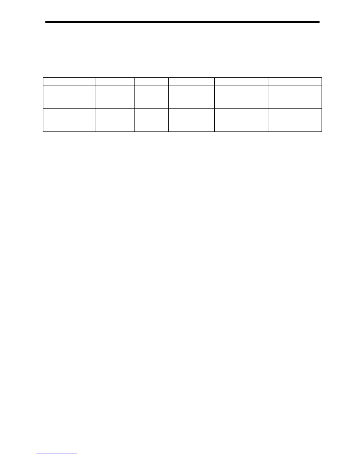
3.3 Electric Specification Sheet
Table 3-2 cable size, overload relay and fuses
Description Voltage(V) AMP (A) SF AMP (A) Frequency(HZ)
Inlet Cable
Size No.
Main Overload
Relay (A)
As a general rule take the motors full load amp(FLA) X1.25 or (25%) = to determine
your breaker & wire size;
CAUTION:
All electrical work must be performed by a qualified electrician and must conform to
national, state, and local electrical code in your area.
NOTE:
- The starting method is delta
- When change the voltage, the electrical component will be changed;
- Component is CSA or UL cert.
230 23.6 27.1 60 No. 10 Wire
460 11.8 13.6 60 No. 14 Wire
575 10.2 11.8 60 No. 14 Wire
230 - - 60 22~30
460 - - 60 12.5~18
575 - - 60 8.5~12.5
LPRS-11
- 19 -

Operation manual
4.0: CONTROLLER
4.1 Introduction:
In general, the controller has following functions:
l Controlling the compressor
l Protecting the compressor
l Monitoring components subject to service
l Automatic restart after voltage failure
Automatic Control of the Compressor
The controller maintains the net pressure between programmable limits by automatically
loading and unloading the compressor. A number of programmable setting e.g. the
unloading and loading pressures, the minimum stop time and the maximum number of
motor starts are taken into account.
The controller stops the compressor whenever possible to reduce the power consumption
and restarts it automatically when the net pressure decreases.
Protecting the compressor
Shut-down
If the compressor outlet temperature exceeds the programmed shut-down level, the
compressor will be stopped. The compressor will also be stopped in case of overload of
the drive motor.
Shut-down warning
A shut-down warning level is a programmable level below the shut-down level.
If one of the measurements exceeds the programmed shut-down warning level, this will
also be indicated on the display to warn the operator before the shut-down level is reached.
Service warming
If the service timer exceeds a programmed value, this will be indicated on display to warn
the operator to carry out some service action.
Automatic restart after voltage failure
The controller has a built-in function to automatically restart the compressor when the
voltage is restored after voltage failure. This function is deactivated in compressor
leaving the factory. If desired, the function can be activated.
4.2 Controller Panel
4.2.1 Interface
6 tactile feedback push button type keys integrated in to the front overlay design. 95
element custom backlit LCD
- 20 -
 Loading...