

LAPLACE INSTRUMENTS RF300 Mk II-A User Manual

Laplace Instruments Ltd
LAPLACE INSTRUMENTS LTD
RF300
Large Loop Antenna
(Van Leen Loop)
2 metre diameter
Mk II-A
USER MANUAL
Ver 2.00 October 2011
Serial number: XXXX
Page 1

Laplace Instruments Ltd
This Page intentionally blank
Page 2

Index
1.0 Introduction
2.0 Packing List
3.0 Assembly
4.0 Calibration loop
5.0 Calibration
6.0 Operation
Appendix
A. Calibration data
B. Latest changes to standards
Laplace Instruments Ltd
CISPR15 & CISPR16.
Page 3

Laplace Instruments Ltd
This Page intentionally blank
Page 4

Laplace Instruments Ltd
1.0 Introduction
The RF300 large loop antenna has been developed to meet the
requirements of EN55015: 2006 + A2: 2009, section 9.9.1, which
refers to CISPR16-1-4: 2007 + A1: 2008 section 4.6.1. This specifies
the limits for magnetic field induced current for luminaires with lamp
operating frequencies in excess of 100Hz.
Construction of the RF300 is as detailed in annex C of EN55016. This
antenna is fully compliant with the standard and details of the
calibration factors are included in this manual. These antenna factors
should be added to the results to obtain correct measurements that
can be compared directly with the limits.
Test setup and limits should be conducted as required by EN55015,
section 4.4.
The design of the RF300 is such that it can be readily erected and
provide a rigid and stable configuration for accurate and repeatable
measurements.
A calibration loop (RF300C) is available as an option if on-site
calibration is deemed necessary. The RF300C allows the calibration
loop to be used on all three axes and rotated within each as required
by the standards.
Page 5
Laplace Instruments Ltd
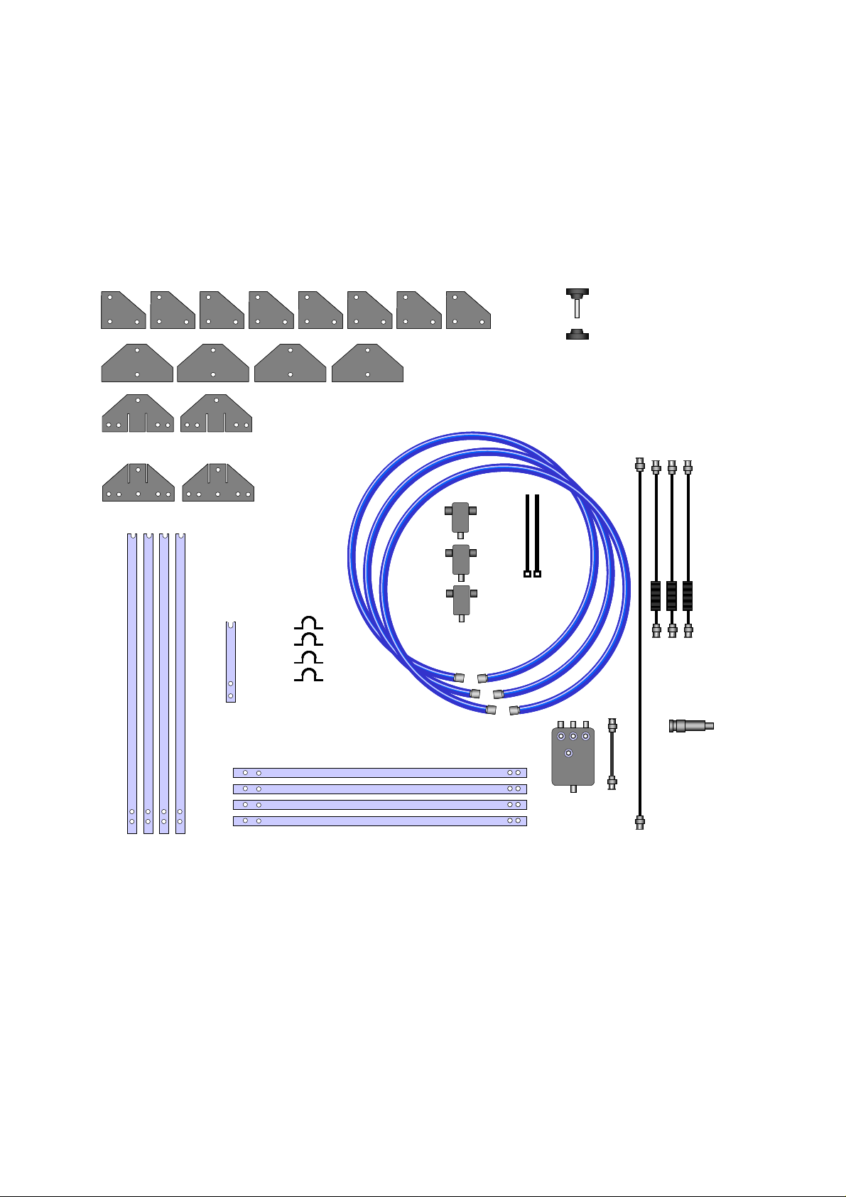
2.0 Packing List
On receipt of the RF300, check the contents of the packages against the
diagram shown in fig 1.
Qty 31 Grip
Qty 31 Grip
Screws and
Screws and
qty 31 grip nuts
qty 31 grip nuts
Qty 8 M6 x 12 screws
Qty 8 M6 x 12 screws
Qty 8 M6 nuts
Qty 8 M6 nuts
Qty 2 Plate B
Qty 2 Plate B
Qty 4
Qty 4
Plate C
Plate C
Qty 3 loops
Qty 3 loops
Qty 8
Qty 8
Plate D
Plate D
Qty 2 Plate A
Qty 2 Plate A
Qty 4
Qty 4
Corner
Corner
posts
posts
Central
Central
pillar
pillar
Qty 4
Qty 4
Saddle clips
Saddle clips
Qty 4 Base extensions
Qty 4 Base extensions
Qty 3 Loop
Qty 3 Loop
transducers
transducers
Qty 2
Qty 2
tiewraps
tiewraps
Identify each component and check for shortages.
Switch unit
Switch unit
with cable
with cable
Qty 3
Qty 3
loop
loop
leads
leads
10dB
10dB
attenuator
attenuator
Qty 1
Qty 1
5m cable
5m cable
Page 6

Quantity Item
2 Plates A
2 Plates B
4 Plates C
8 Plates D
3 Loop antennas (Blue)
4 Corner posts
4 Base extensions
Laplace Instruments Ltd
1 Central pillar
4 Saddle Clips
31 Grip screws (M10)
31 Grip nuts (M10)
8 M6 x 12 screws and nuts
3 Loop transducers (current sensors)
1 Switch Unit
1 Short BNC—BNC cable, patch cable
1 BNC—BNC cable (5m), output cable
3 BNC—BNC cable (1.5m), loop leads
1 10dB attenuator
2 Tiewraps
Page 7
Laplace Instruments Ltd
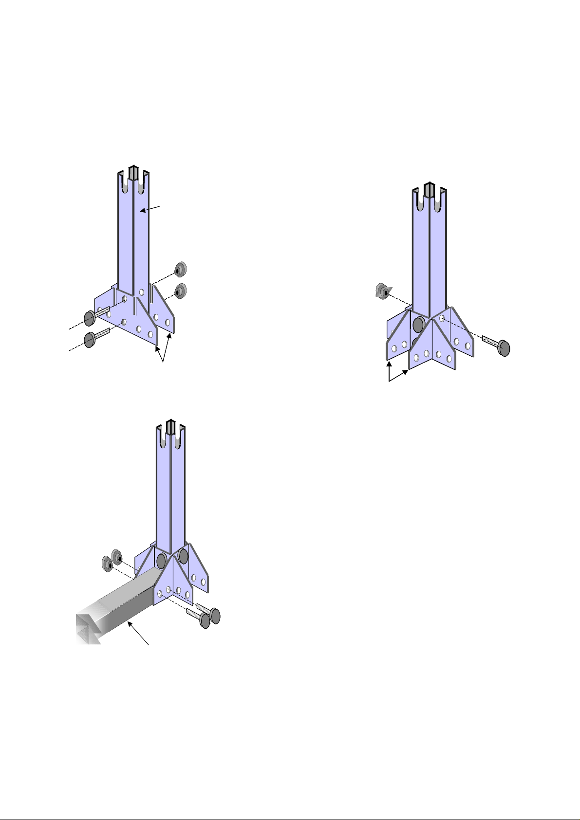
3.0 Assembly
3.1 Stage 1 Central sub-assembly
Establish a clear area with a level floor clear of metallic structures and
having a 3m clearance height.
1(a)….Secure Plates A to
the central pillar using the
supplied grip screws..
Note that the plates have
tapered holes to mach the
taper on the grip screws,
so ensure that these
plates are assembled
correct way round.
1(b)….Secure Plates B as
shown in fig 3.
Plates BPlates B
Figure 3
1(c)…..Place the central post assembly in the
centre of the prepared area and add the 4 base
extensions, each using 2 grip screws.
Plates A
Plates A
Figure 2
Horizontal strut
Repeat in 4 places
Figure 4
Central pillar
Central pillar
Page 8
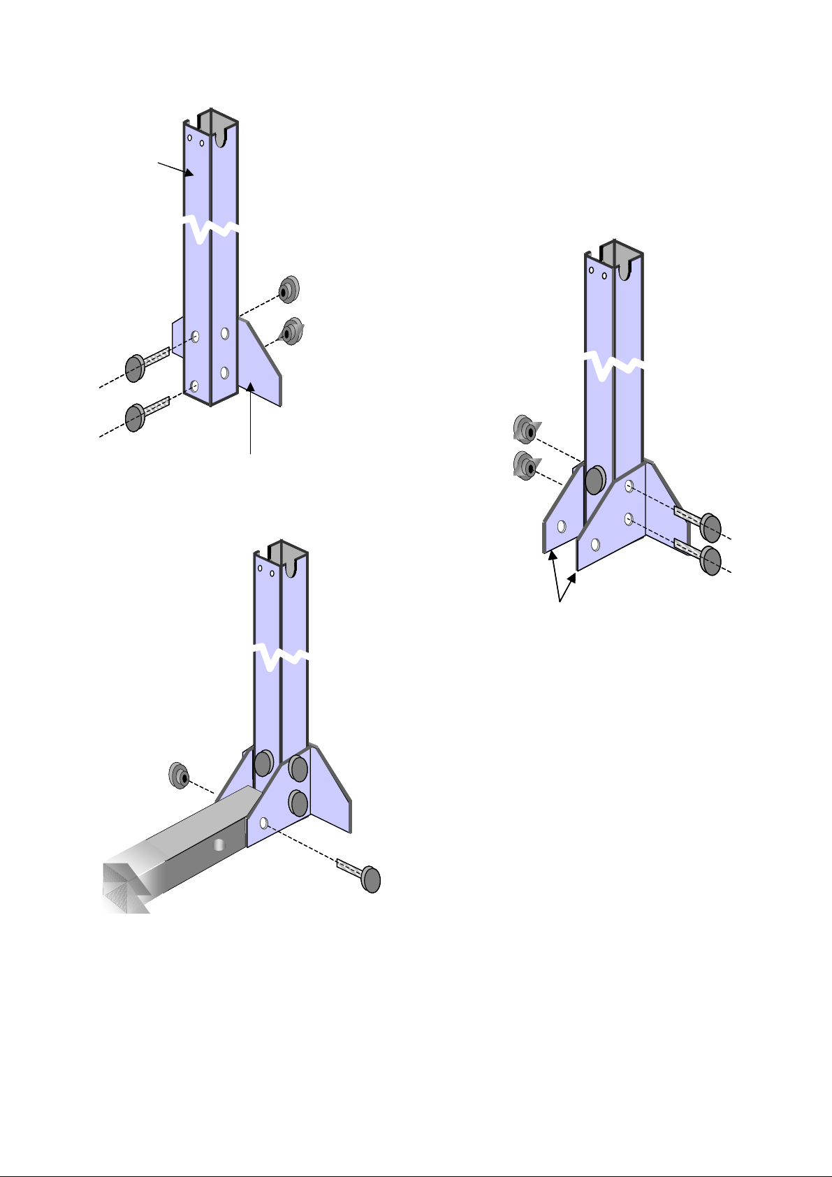
Corner
Corner
post
post
Figure 5
Plate C
Plate C
Join posts to
Join posts to
horizontal struts
horizontal struts
Laplace Instruments Ltd
3.2 Stage 2 Corner post assembly
2(a) ….Add plate C to the base of each corner
post using 2 grip screws. Repeat for the other
corner posts. Note that the plate is fitted on the
opposite side to the 2 mounting holes at the top
of the post.
2(b)…. Add the 2 Plates
D to each corner post
as shown. In Fig 6.
Plates DPlates D
Figure 6
2(c.)…..Secure the corner posts to the
outer end of each base extension.
Figure 7
Page 9
Laplace Instruments Ltd
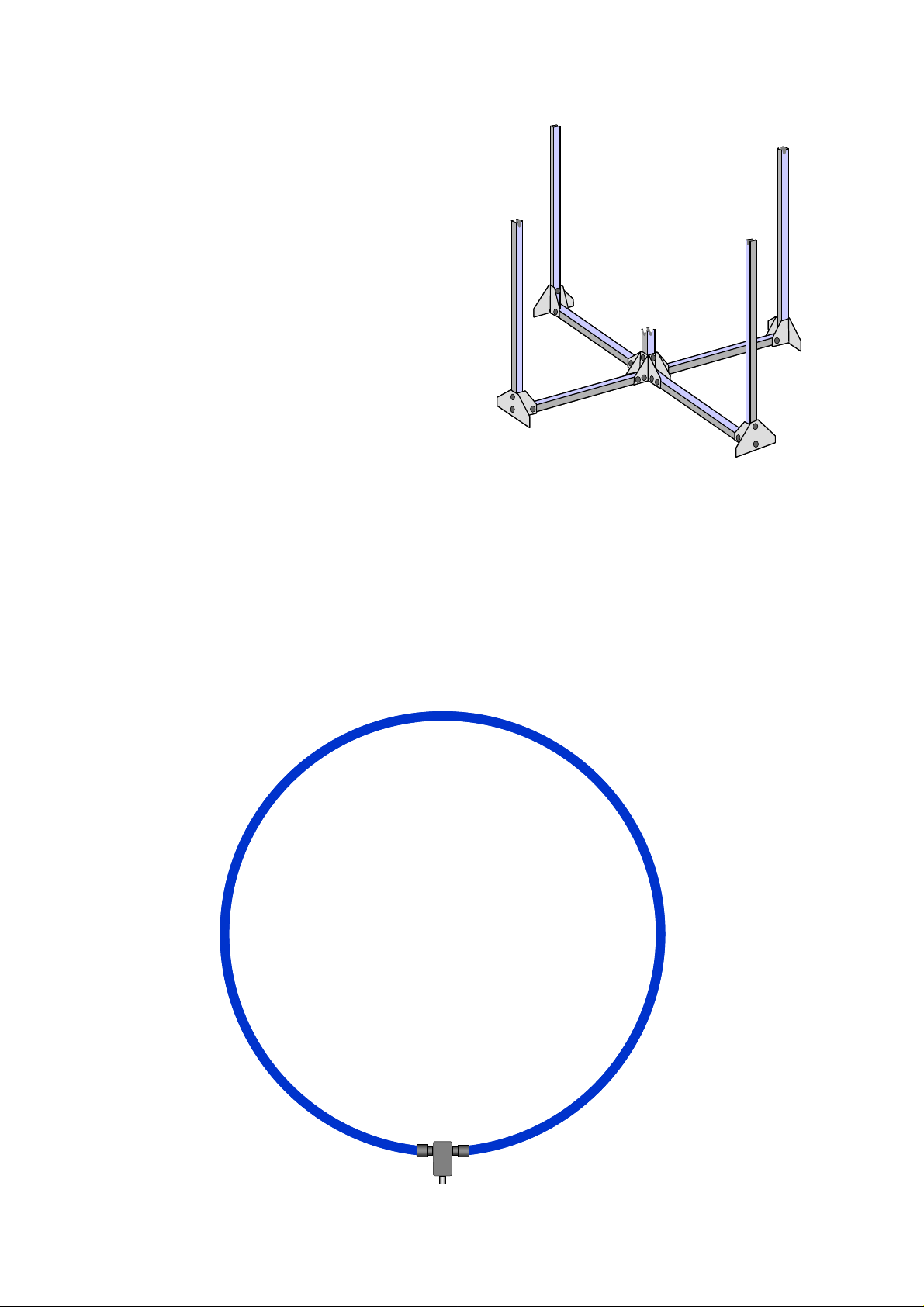
3.3 Assembly of Loops
The frame should now look like that
shown in Figure 8.
The next steps are to add the loops.
Figure 8
3.3(a) The configuration of these loops is as shown in fig 9 and fig 10.
The connectors on each end of the loop are mated with the sockets either
side of each loop transducer. The retaining ring on each connector needs
to be screwed firmly to the socket but take care. These rings will bind
and be difficult to turn unless the loop is aligned properly. Force is not
necessary, simple jiggle the loop into alignment and the ring will turn
easily.
Figure 9
Page 10
 Loading...