


RF200
Antenna
User Manual
Version 3.0
January 2004
LAPLACE INSTRUMENTS LTD
3B, Middlebrook Way
CROMER
Norfolk NR27 9JR
UK
Tel: 012 63 51 51 60
Fax: 012 63 51 25 32

RF200/500 user manual
2
Index
1.0 Introduction Page 3
Background
2.0 RF200 broadband antenna Page 4
Assembly Page 4
In use Page 6
Antenna Factor Page 7
3.0 Ground Plane Page 8
4.0 Test site calibration Page 9

RF200/500 user manual
3
1.0 Introduction
1.1 Antenna Background
For measurement of field strength (far field emission level) an antenna is required
which will act as a transducer, converting field strength (mV/m) to mV signals output
down a coax cable.
Antennas to cover the wide frequency ranges required by the legislation are not simple
devices! The standards call for the use of a ‘tuned dipole’. Whilst this is simple to
manufacture and produces a easily definable output, it will only work at one
frequency, the tuned frequency. Dipoles are tuned by adjusting the length of their
elements. For serious emissions measurement work, the constant retuning of the
antenna for each peak of interest is time consuming, hence the introduction of ‘broad
band’ antennas that cover a wide spectrum without the need for any retuning. These
include log periodic, bi-conical, bi-log and other specialist types. All suffer from
variation of sensitivity with frequency and need a correction chart so that the
appropriate adjustment can be made to the spectrum. This correction chart is called
the antenna factor.
The Laplace RF200 broadband antenna has a relatively ripple free antenna factor
characteristic, close to the optimum.
If the antenna is used with the Laplace EMC analysers and the EMCEngineer
software, selection of the RF200 item in the input menu automatically applies the
RF200 antenna factor correction to the spectrum.
1.2 Dipole or broadband antenna, which to use?
EN50022 specifies that a tuned dipole be used as the antenna for radiated emissions
testing. The dipole is a basic standard that, at its tuned frequency, has an easily
definable output vs field strength characteristic. Dipoles are tuned by adjusting the
length of each element to be ¼wavelength long. If measuring the emissions from a
product over a wide frequency range, this is tedious, time consuming and is a source
of error. Broadband antennas have a known response over a wide range of
frequencies and need no adjustment. The response is not flat, and all broadband
antennas should be supplied with an ‘antenna factor’ curve. This is a plot of
sensitivity vs frequency over the full working range of the antenna. The RF200 has a
working range of 30MHz to 1GHz and thus matches the requirements of the EN
standards.
The RF200 may be used with any analyser or receiver but the SA1020 pre-amplifier
should be used to ensure that the characteristics of the antenna match the published
data.
Basically, you need the Broadband antenna if it is necessary to measure absolute field
strength with a reasonable level of confidence and have an effective test site, free of
reflections.
Note that the antenna factor for the RF200 is included in the SA1000 software.
This antenna means that you can cover the whole radiated emissions frequency range
in one sweep. No need to adjust dipoles to each frequency of interest, no need to
switch between log periodic and biconical types half way through the testing.

RF200/500 user manual
4
2.0 RF200 Broadband antenna
The broadband antenna will allow the user to detect and measure radiation over the
frequency range 30MHz to 1GHz.
This is shipped in a ‘knocked-down’ form to ease packaging and to minimise the
potential for damage in transit. Assembly is straightforward but must be done with
care.
The basic design of the antenna consists of a central main beam, itself comprising two
parallel aluminium sections spaced apart by insulators. Equal length pairs of stainless
steel rods form the antenna elements, these mounted on the main beam in order of
length, the shortest at the end from which the output lead is attached. An insulating
mounting block provides attachment for the stand with facilities for horizontal and
vertical mounting. The non-metallic stand allows adjustment of antenna height and
direction.
2.1 Antenna assembly (see fig 1)
1. The aluminium alloy elements are secured to the central beam using the M4 bolts
and washers provided. An M4 hex driver is also included to facilitate assembly. These
elements are mounted in equal length pairs with the shortest at the end of the central
beam where the output cable is attached. There are two copper crinkle washers with
each bolt. Ensure that one washer is under the bolt head and the other is under the
antenna element. Tighten the bolts until the crinkle washer is flat. Do not overtighten
as this may distort the beam. Alternate the element direction as shown in the diagram
so that for each side of the central beam, the elements alternate up, down, up,
down...etc. until element 9 which is out-of-sequence and is mounted same side as
element 8. Element 10 is alternate to element 9 as shown in Fig 1.
3. The number of elements (10 pairs) should match the number of hole pairs along the
central beam.
4. A pre-drilled plastic block is supplied to form a central mounting block and preamp support. This is screwed to both beams using the supplied nylon screws.

RF200/500 user manual
5
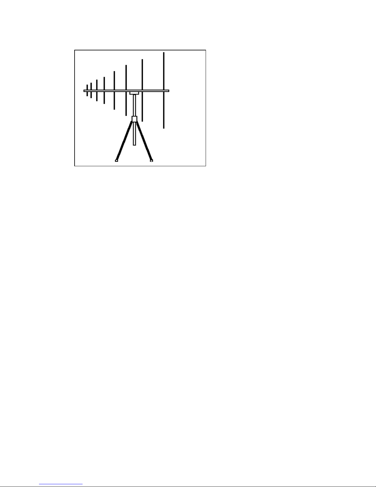
Fig 1 RF200 Assembly
RF200 Stand assembly
RF200/500 user manual
6
Fig 2 RF200 stand
This is supplied as a central vertical support fitted with a leg attachment moulding and
three legs.
The legs are a push fit into the leg attachment moulding.
The vertical support has a friction slide fit in the leg attachment moulding so that the
antenna can be adjusted in height over the full length of the vertical support.
The antenna is located on the stand by locating the central support block on the top of
the vertical support in either the horizontal or vertical polarisation position. Nylon
bolts are provided so that the antenna can be clamped in position
If used outdoors in strong wind conditions, the stability of the antenna can be
considerably increased by filling a bag with sand, soil or stones and supporting it by
string tied round the leg attachment moulding.
2.2 RF200 in use
Connect the SA1020 pre-amplifier directly to the antenna output lead and secure the
pre-amp to the central support block with the velcro strips. Ensure that the connection
to the antenna is made to the input of the pre-amplifier. It is easy to get the amplifier
wrong way round!!
Point the antenna, sharp end forward, at the UUT. Note that the antenna is directional
but full sensitivity is maintained over a wide angle either side of ‘dead ahead’.
The reference point for the measurement of EUT – Antenna distance is the central
mounting point, where the vertical pole meets the horizontal main antenna beams.
The height of the antenna can be changed by sliding the vertical support up or down
within the leg attachment moulding. If this friction fit is too slack or tight, slightly
adjust the nylon bolt to suit. Note that antenna height may be a critical factor in
obtaining valid results. See section 4 on Ground Plane.
The main feature of the polar plot of the antenna (i.e. its directional properties) is a
sharp null at 90º on either side. This can be used to null out any strong background
emission for instance from an FM radio transmitter IF using a true open field site.
Note that the null is very sharp and care has to be taken to find the right angle.
Attenuation of up to 20dB is possible under the right conditions. In the presence of
buildings etc., these emissions will be affected by reflections and will not be
unidirectional, making them impossible to null out.

RF200/500 user manual
7
2.3 Antenna Factor
The sensitivity of any antenna will vary with frequency. i.e. it will be more sensitive at
some frequencies and less sensitive at others. A plot of sensitivity vs frequency is
called the Antenna Factor.
The SA1000 Windows software has the antenna factor for the RF200 broadband
antenna ready installed. Selecting this item in the INPUT menu automatically applies
the appropriate conversion to read out in absolute field strength.
WARNING: Although the conversion is valid, the field strength measured by the
antenna is subject to your test site conditions and configuration and may be subject to
gross errors. Reception of emissions radiated from the UUT depend on the test
conditions, the test site, reflections, ground plane, background radiation, UUT to
antenna distance etc..etc.. Be very wary about relating field strengths to limit lines
unless you have some known test results to act as a reference.
Fig 3(a) RF200 Antenna factor, linear frequency scaling.
Note. Antenna factor includes SA1020 Pre-amplifier and 5 metres co-ax cable.
A.F. (dB)
-15
-12.5
-10
-7.5
-5
-2.5
0
2.5
5
7.5
10
12.5
15
0
100
200
300
400
500
600
700
800
900
1000
Frequency (MHz)
Antenna gain (dB)
A.F. (dB)
Fig 3(b) RF200 Antenna Factor, Log frequency scaling
Note. Antenna factor includes SA1020 Pre-amplifier and 5 metres co-ax cable.
A.F. (dB)
-15
-12.5
-10
-7.5
-5
-2.5
0
2.5
5
7.5
10
12.5
15
10
1000
Frequency (MHz)
Antenna gain (dB)
A.F. (dB)
RF200/500 user manual
8
Antenna Factor tabular data
Freq(MHz) A.F. (dB/m)
30 0
40 -1
50 -2
60 -3
70 -5
80 -7
100 -9
120 -9
140 -8
160 -7
180 -6
200 -5
Freq(MHz) A.F. (dB/m)
220 -3
240 -2
260 -4
280 -5
300 -3
320 -2
340 -1
360 0
380 1
400 2
420 3
440 3
Freq(MHz) A.F. (dB/m)
460 4
480 5
500 5
550 6
600 7
650 9
700 10
750 11
800 12
850 13
900 13.5
950 14
1000 14.5
3.0 Ground plane
In general, any UUT will emit radiation in all directions. Some of this will impinge on
the ground which will partially reflect this radiation.
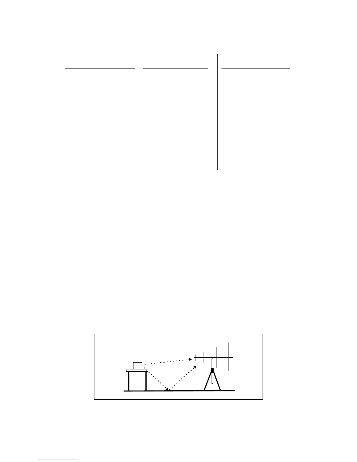
When measuring emissions in the far field, the signal received by the antenna will
comprise a direct signal and a signal which has been reflected from the ground.
(Assuming that the test site has been chosen so that no other reflections are present).
The amount of this reflected signal depends on ground conditions and may vary very
considerably in amplitude. On ‘soft’ ground such as earth (soil) the reflection will
vary from day to day as conditions change. This means that the integrity and
consistency of the results will be variable. To overcome this problem, the standards
require a test site to have a metal ground plane consisting of a continuous metal sheet
(or equivalent) under the UUT and between the UUT and the antenna. This gives a
consistent 100% reflection. This is in one sense ‘worst case’ because the effect of the
reflection will be maximised, but at least it will be consistent.
The effect of the reflection will depend on frequency and the difference in path length
between the direct path and the reflected path. If this difference is equal to half a
wavelength at the frequency of interest, the two signals will be 180° out of phase and
will cancel, producing up to 20dB reduction in signal strength.
Fig 4 Ground plane reflection
UUT
Direct path
Reflected
path
RF200/500 user manual
9
1.00
1.10
1.20
1.30
1.40
1.50
1.60
1.70
1.80
1.90
2.00
2.10
2.20
2.30
2.40
2.50
2.60
2.70
2.80
2.90
3.00
3.20
3.40
3.60
3.80
4.00
4.20
4.40
4.60
50
100
150
200
250
300
350
400
450
500
550
600
650
700
750
800
850
900
950
1000
antenna height
MHz
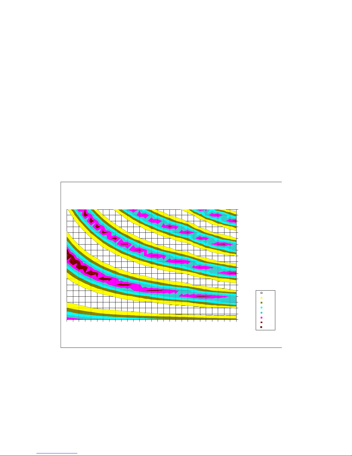
3-6
0-3
-3-0
-6--3
-9--6
-12--9
-15--12
-18--15
To overcome this effect, the standards call for the antenna to be mounted on a mast so
that it can be varied in height over a range of 1 to 4 metres. For each frequency there
will be a height at which the two signals are in phase and additive. This is the height
at which that frequency is measured.
Fig 5 shows the relationship between frequency, antenna height and signal
gain/attenuation. The white areas correspond to gain and the dark areas represent
attenuation.
If using an open field site on dry soil, the reflection will be small and the
gain/attenuation effect will be minimal. However, if any metal surface is in the
vicinity (filing cabinet for instance) this chart gives some idea of the consequences!
Note that the chart is correct for the conditions listed only. If for instance the
polarisation is changed to vertical the plot will completely change.
Fig 5 Ground plane effect
Conditions: Product height: 0.8m
Antenna distance: 3m
Polarisation: Horizontal
Ground plane: Metal sheet (ideal)
4.0 Test Site Calibration
Any area or test cell used for far field radiation testing should be calibrated. Purpose
made cells such as a G-TEM cells are supplied ready with a calibration sheet which
defines the characteristic relationship between UUT emissions and cell output vs
frequency.

RF200/500 user manual
10
If using a an open field test site, this should also be calibrated. The ground plane
reflection alone can have a significant effect on the test results. To calibrate a site, a
known source should be used. Laplace can supply a calibrated source, complete with
calibration curves, which is specifically designed for the calibration of sites and
antennas. Contact Laplace for details of this ERS (Emission Reference Source). An
alternative for achieving a rough calibration is to use a product with known emissions
(i.e. one which has already been tested at a test house) on your test site under exactly
the same conditions as applied during the test house measurement. By correlation of
your results with the test house results, an approximate calibration of the site can be
derived. Note that if the site is outdoors, it will need a calibration check every time it
is used because weather conditions can affect the site significantly.
Drawbacks to this technique are the problems of obtaining consistent emissions from
a product and the fact that the correlation can only be applied at those frequencies for
which emissions exist.

RF200/500 user manual
11
LAPLACE INSTRUMENTS LTD
3B, Middlebrook Way
Cromer
Norfolk
NR27 9JR
Tel: +44 (0) 12 63 51 51 60
Fax: +44 (0) 12 63 51 25 32
E: tech@laplace.co.uk
Web: www.laplaceinstruments.com
 Loading...