

Page 1

LETIS
Laplace EMC Test Integration System
User Guide
Issue 1.0
May 2005
LAPLACE INSTRUMENTS LTD
Page 2
INTRODUCTION
The LETIS is designed to simplify the operation of integrated emissions and
immunity test systems based on the Laplace range of equipment. It will automatically
switch power amplifiers at the appropriate range change frequency (normally 1GHz)
and permit switching between immunity mode and emissions measurement mode.
The LETIS is controlled via USB port from the standard RFSynth software provided
with the RF1000, RF2000 or RF3000 synthesisers.
Safety features include the switching of power amplifiers to ‘standby’ mode when
they are not ‘on-line’ and segregation of RF feeds between the emissions path and the
immunity path.
Operation can be either fully automatic, or manual from the front panel.
Description
The LETIS uses the same case format as the standard Laplace range of
instrumentation and can be stacked in the normal manner. Power is provided by mains
and has an auto sensing PSU which can accept 110V – 240V, 50/60Hz.
The USB port and mains power socket are on the rear panel, all other connectors and
controls are on the front panel.
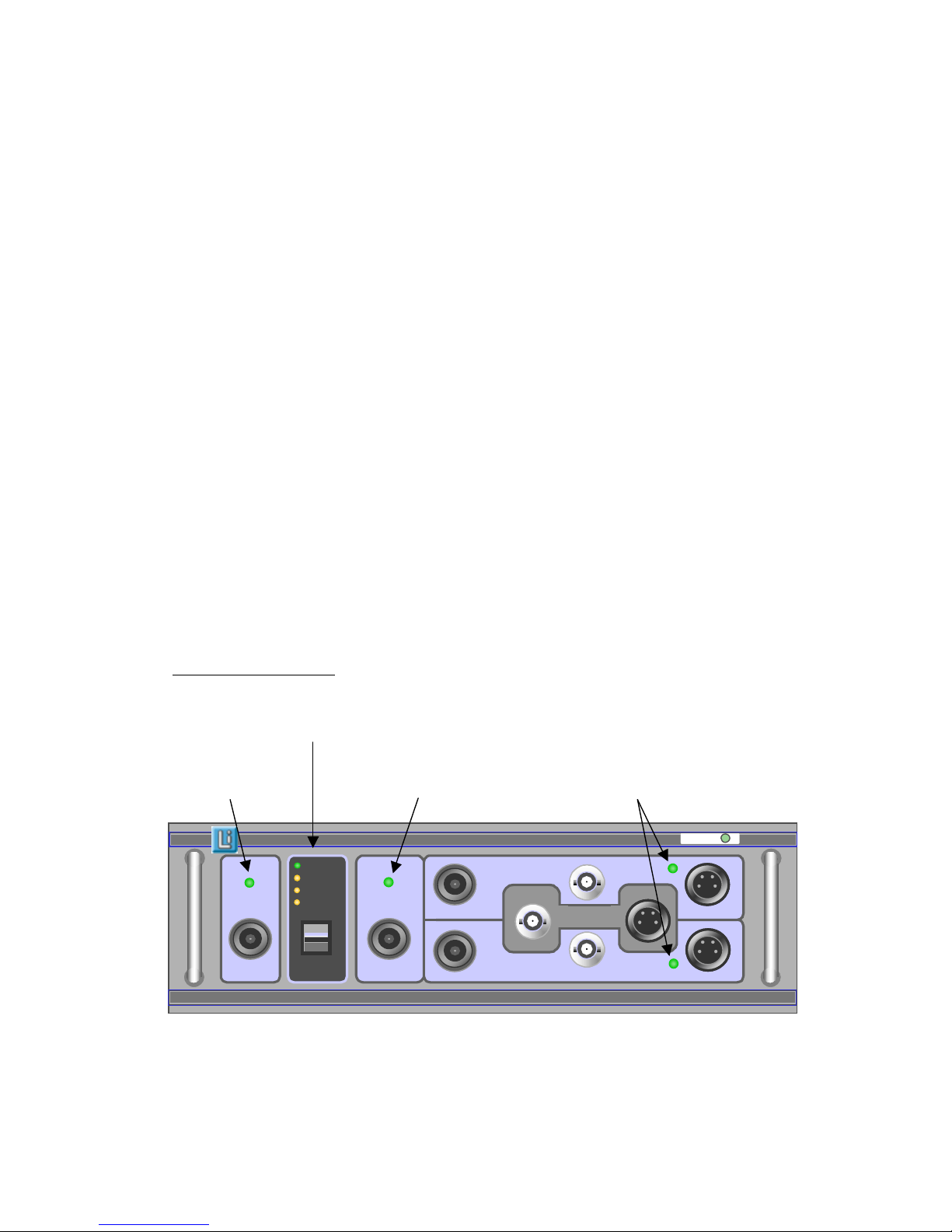
Front Panel
Controls and indicators
Mode Selector switch
with mode indication
Emissions mode Immunity mode Amplifier selected
Indicator indicator indicator
RF connection
to cell
Power
Laplace Instruments Ltd
LETIS -Laplace EMC Test Integration System
Made in UK
Amplifier 1 connections
Amplifier 2 connections
To emissions
analyser
EMISSIONS
IMMUNITY
Auto
Emissions
Amp 1
Amp 2
To Synthesiser
RF connection
to cell
RF connection
to cell
Power Power
Laplace Instruments Ltd
LETIS -Laplace EMC Test Integration System
Made in UK
Amplifier 1 connections
Amplifier 2 connections
Amplifier 1 connectionsAmplifier 1 connections
Amplifier 2 connectionsAmplifier 2 connections
To emissions
analyser
To emissions
analyser
EMISSIONSEMISSIONS
IMMUNITYIMMUNITY
AutoAuto
EmissionsEmissions
Amp 1Amp 1
Amp 2Amp 2
To SynthesiserTo Synthesiser
Page 3
Connections
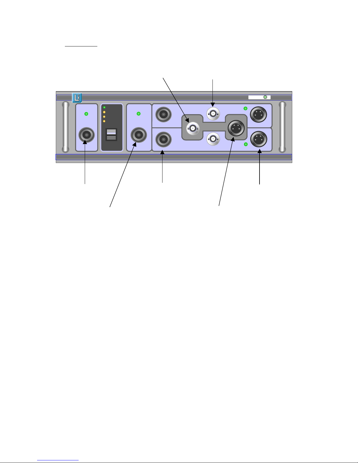
RF signal from RF signals
Synthesiser to power amps
RF to emissions RF connections Interlocks to
Analyser to power amps power amps
RF connection Interlock from
to cell synthesiser
Operation
1. Connect all cables as shown below.
2. Switch all units on.
3. The LETIS should default to Auto, Emissions mode.
4. The system can be used for emissions testing only at this stage.
5. For auto operation and immunity testing, connect the USB cable from the
LETIS and the PC.
6. Run the RFSynth software.
7. The LETIS will switch to a power amplifier only when actually running an
immunity test.
8. If you need emissions testing, simply close the RFSynth software.
9. For immunity testing, leave the mode in Auto. The power amplifiers will
automatically switch at 1GHz.
NOTES
∗ If not using the RFSynth software, the mode selector switch can be used to
operate the system in Manual mode.
∗ If the switch is used to exit Auto mode, the RFSynth software must be
restarted to resume Auto operation.
RF connection
to cell
Power
Laplace Instruments Ltd
LETIS -Laplace EMC Test Integration System
Made in UK
Amplifier 1 connections
Amplifier 2 connections
To emissions
analyser
EMISSIONS
IMMUNITY
Auto
Emissions
Amp 1
Amp 2
To Synthesiser
RF connection
to cell
RF connection
to cell
Power Power
Laplace Instruments Ltd
LETIS -Laplace EMC Test Integration System
Made in UK
Amplifier 1 connections
Amplifier 2 connections
Amplifier 1 connectionsAmplifier 1 connections
Amplifier 2 connectionsAmplifier 2 connections
To emissions
analyser
To emissions
analyser
EMISSIONSEMISSIONS
IMMUNITYIMMUNITY
AutoAuto
EmissionsEmissions
Amp 1Amp 1
Amp 2Amp 2
To SynthesiserTo Synthesiser
Page 4
∗ When in Auto mode, pressing the mode selector switch down will exit Auto
mode (green LED turned off) but leave the selected channel unchanged.
Therefore use the Up or Down positions to select the required channel. If the
switch is used UP to reselect Auto operation, the RFSynth software must be
restarted (as described above).
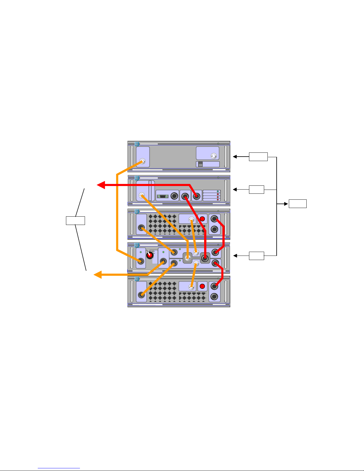
The diagram shows a typical system with SA1000 emissions analyser, RF2000
synthesiser, RF1100 and RF1200 power amplifiers. All other configurations will be
similar or have some sections omitted.
To Cell
Control
RF
RS232
USB
USB
To PC
To Cell
Control
RF
RS232
USB
USB
To PC
 Loading...