


FEXTEASE1000-02
EASE1000
User's Manual
2nd Edition
Issue Date: December 15, 2017
LAPIS Semiconductor Co., Ltd.

NOTES
1) The information contained herein is subject to change without notice.
2) Although LAP IS Semico nductor is continuo usly wor king to i mprove pr oduct rel iability a nd qualit y, semicond uctors c an
break down and malfunction due to various factors. Therefore, in order to prevent personal injury or fire arising from
failure, please take safety mea sures such as co mplying with the d erating charact eristics, imple menting redunda nt and
fire preventi o n d e sig ns, a nd ut il izi n g ba ck up s a nd fai l -safe proced ures. LAPIS Semiconductor shall have no responsibility
for any damages arising out of the use of our Products beyond the rating specified by LAPIS Semiconductor.
3) Examples of application circuits, circuit constants and any other information contained herein are provided only to
illustrate the standard usage and operations of the Products.The peripheral conditions must be taken into account when
designing circuits for mass production.
4) The technical information specified herein is intended only to show the typical functions of the Products and examples of
application circuits for the Products. No license, expressly or implied, is granted hereby under any intellectual property
rights or other rights of LAPIS Semiconductor or any third party with respect to the information contained in this
document; therefore LAPIS Semiconductor shall have no responsibility whatsoever for any dispute, concerning such
rights owned by third parties, arising out of the use of suc h technical i nformatio n.
5) The Products are intended for use in general electronic equipment (i.e. AV/OA devices, communication, consumer
systems, gaming/entertainment sets) as well as the applications indicated in this document.
6) The Products specified in this document are not designed to be radiation tolerant.
7) For use of our Products in applications requirin g a high degree of reliability (as exemplified below), please contact and
consult with a LAPIS Semiconductor representative: transportation equipment (i.e. cars, ships, trains), primary
communication equipment, traffic lights, fire/crime prevention, safety equipment, medical systems, servers, solar cells,
and power transmission systems.
8) Do not use our Products in applications requiring extremely high reliability, such as aerospace equipment, nuclear power
control systems, and submarine repeaters.
9) LAPIS Semiconductor shall have no responsibility for any damages or injury arising from non-compliance with the
recommended usage conditions and specifications contained herein.
10) LAPIS Semiconductor has used reasonable care to ensure the accuracy of the information contained in this document.
However, LAPIS Semiconductor does not warrant that such information is error-free and LAPIS Semiconductor shall
have no responsibility for any damages arisi ng from any inaccuracy or misprint o f such information.
11) Please use the Products in accordance with any applicable environmental laws and regulations, such as the RoHS
Directive. For more details, including RoHS compatibility, please contact a ROHM sales office. LAPIS Semiconductor
shall have no responsibility for any damages o r losses re s ulting non -compliance with any applicab le laws or regulations.
12) When providing our Products and technologies contained in this document to other countries, you must abide by the
procedures and provisions sti pulated in all applicable export laws and regulations, inc luding without limitation the US
Export Ad mi nistration Regulatio ns and the Foreign Excha nge and Fore ign Trade Act .
13) This document, in part or in whole, may not be reprinted or reproduced without prior consent of LAPIS Semiconductor.
Copyright 2017 LAPIS Semiconductor Co., Ltd.
2-4-8 Shinyokohama, Kouhoku-ku,
Yokohama 222-8575, Japan
http://www.lapis-semi.com/en/
FEXTEASE1000-02 1

EASE1000 User’s Manual
Table of Contents
Table of Contents
Chapter 1 PREFACE
For Safe and Correct Operation ............................................................................................................... 1
Precautions ............................................................................................................................................... 2
Description of Term .................................................................................................................................. 4
Chapter 2 General Description
2 General Description ................................................................................................................................. 1
2.1 Product Overview ............................................................................................................................... 1
2.2 EASE1000 Components ..................................................................................................................... 2
2.3 Appearance ........................................................................................................................................ 3
2.4 Terms of Use ...................................................................................................................................... 4
2.5 Target System Requirements ............................................................................................................. 5
2.5.1 Target System Circuit Configuration ............................................................................................. 6
2.5.1.1 ML62Q1000 series is connected as target LSI ......................................................................... 6
2.5.1.2 ML610Q100 or ML620Q000 is connected as target LSI .......................................................... 7
2.5.1.2.1 Recommended circuitry using RESET_N pin and TEST pin ............................................... 7
2.5.1.2.2 Recommended circuitry using TEST1_N pin and TEST0 pin .............................................. 8
2.6 Supplying Target LSI VDD ............................................................................................................... 9
2.6.1. Supplying Target LSI VDD from EASE1000 .............................................................................. 9
2.6.2 Outputting Target System Power Supply to Target LSI VDD ..................................................... 9
2.7 Target System Board Layout ............................................................................................................ 10
2.7.1 Notes of Target System Board Layout ....................................................................................... 10
Chapter 3 START
3 START ..................................................................................................................................................... 1
3.1 Starting EASE1000 ............................................................................................................................. 1
3.1.1 Starting Procedure ........................................................................................................................ 1
3.1.2 Removal Procedure ...................................................................................................................... 2
Chapter 4 FUNCTIONS
4 FUNCTIONS............................................................................................................................................ 1
4.1 On-chip debug function ...................................................................................................................... 1
4.2 Flash writer function ........................................................................................................................... 1
4.3 Indicator .............................................................................................................................................. 1
Chapter 5 Notes on Use of EASE1000
5 Notes on Use of EASe1000 .................................................................................................................... 1
5.1 Notes on Debug .................................................................................................................................. 1
5.2 About the 3.3VOUT pin ...................................................................................................................... 2
5.3 About Usage Environment .................................................................................................................. 2
5.4 About Flash Writing ............................................................................................................................ 2
5.5 About Cables ...................................................................................................................................... 2
5.5 About EASE1000 interface cable connection ..................................................................................... 2
Chapter 6 Appendices
6 Appendices .............................................................................................................................................. 1
6.1 Form information................................................................................................................................. 1
6.1.1 EASE1000 ..................................................................................................................................... 1
6.1.2 EASE1000 Interfac e c able ............................................................................................................. 1
6.1.3 USB cable ...................................................................................................................................... 1
FEXTEASE1000-02 i
EASE1000 User’s Manual
Table of Contents
6.2 EASE1000 Interface Cable Appearance ............................................................................................ 2
6.3 Update of Firmware ............................................................................................................................ 2
Revision History
Revision History.......................................................................................................................................... 1
FEXTEASE1000-02 ii

Chapter1 PREFACE
EASE1000 User’s Manual
△記号は危険性の存在を知らせ、注意を促す内容があることを告げるものです。
図の中に具体的な注意内容(左図の場合は感電注意)が描かれています。
●記号は行為を強制したり、指示する内容を告げるものです。
図の中に具体的な指示内容(左図の場合は電源プラグをコンセントから抜いて下さい)が描
かれています。
○記号は禁止の行為であることを告げるものです。
図の中に具体的な指示内容(左図の場合は分解禁止)が描かれています。
symbol indicate s a r isk and calls attention. In t he picture, a specific note ("Electric shock
symbol forces an action and indicates the instruction. In the picture, a specific instruction
symbol indicates a banned action. In the picture, a spec ific instruction ("No decomposi tion"
Chapter 1 PREFACE
For Safe and Correct Operation
This user's manual uses various terms and pictorial indications for you to use this product safely and correctly and to
prevent harm to you and others and property damages. Their meanings and displays are as follows:
Meaning of term
Incorrect handling in defiance of this display may cause death or
Warning
Note
Example of pictorial indication
serious injury.
Incorrect handling in defiance of this display may cause injury or
property damage.
△
hazard" in the left figure) is drawn.
●
("Disconnect the power plug from outlet" in the left figure) is drawn.
○
in the left figure) is drawn.
FEXTEASE1000-02 1

EASE1000 User’s Manual
Warning
Note
Chapter 1 PREFACE
Precautions
Be sure to read this page before using this product.
● Do not use the product at a voltage other than specified one.
It might cause fire or electric shock.
● In case of an abnormal state such as reeking or abnormal odor, rapidly disconnect
the power plugs of EASE1000 and any other external powers from outlet.
Leaving such situation as it might ca use fire or electric shock.
● Do not install the product in a wet or high-humidity environment.
It might cause fire or electric shock.
● Do not place any object on the product.
It might cause fire or electric shock.
● If you awake to a ny failure, use caution t o rapidly disconnect the power plugs of
EASE1000 and any other external powers from outlet.
Leaving such situation as it might ca use fire or electric shock.
● Do not place the product on an unstable or slope place.
It might cause falling and injury.
● Do not use the product in a place with excessive vibration, electromagnetical field,
or corrosive gas.
It might lead to loosened or disconnected connections of various cables, causing
failures.
● Do not use the product under out of the operational temperature, direct sunlight, or
dusty condi tion.
It might cause fire or failure.
● Be sure to use the attached cables and accessories.
Other items might cause fire or failure.
● Do not use the attached cables and accessories on other than this system.
It might cause fire.
FEXTEASE1000-02 2

EASE1000 User’s Manual
Note
The EASE1000 is not intended for use for volume production or parts thereof.
● Do not use the EASE1000 for the final check of target LSI of operation.
The obstacle by the wrong usage and reconstruction etc. cannot be guarantee.
Therefore, whe n usi ng the EASE1000, the contents of the manual should check in the newest.
Chapter 1 PREFACE
Be sure to read this page before using this product.
● Do not apply a voltage exceeding the 5.5V to the VTref p in of the EASE1000
Interface cable. It might cause fire or failure.
● The order of power ON and OFF needs extra attention. Incorrect order might cause
fire or failure.
● Be sure t o turn off the EASE1000 before connecting or disconnecting it. Otherwise,
it might cause fire or failure.
● Be sure t o turn off the EASE1000 and the user application system before connecting
or disconnecting them. Otherwise, it might cause fire or failure.
● The EASE1000 is an unfinished product and intended for research and development and for
expert use in the research and development facility only.
● The guarantee period to the initial failure of EASE1000 is one year.
● The content specified herein is subject to change for improvement without notice.
FEXTEASE1000-02 3

EASE1000 User’s Manual
Term
Description
EASE1000
It is an on-chip emulator for microcontroller of Lapis
on-chip emulator function.
DTU8 debugger
It is software to control the on-chip emulator function of
EASE1000 and is a Windows application running on the PC.
MWU16 flash multi writer host program
It is software to control the flash multi writer function of
EASE1000 and is a Windows application running on the PC.
Target system
It is a board having a LSI to be debugged by EASE1000 or
whose flash memory to be written or erased.
Host PC
It is a PC with the DTU8 debugger, MWU16 flash multi
writer host program, and USB d river installed.
USB cable
It is a cable to connect EASE1000 with the host PC.
Target LSI
It is LSI debugged by EASE1000.
EASE1000 interface cable
It is an interface cable to connect EASE1000 with the target
system.
Chapter 1 PREFACE
Description of Term
The following shows the terms used in this user's manual and their de scriptions.
Semiconductor.
It has a function as a writer (hereinafter referred to as flash
writer) to a LSI wit h built-in flas h memory, as well as the
FEXTEASE1000-02 4

Chapter 2 General Description

EASE1000 User’s Manual
Target system
Host PC
Target LSI
EASE1000 interface cable
USB cable
EASE1000
・DTU8 Debugger
・MWU16 Flash Multi Writer
host program
Chapter 2 General Description
2. General Description
2.1 Product Overview
EASE1000 is an on-chip emulator for Microcontroller (hereinafter referred to as target LSI) of Lapis Semiconductor.
In combination with the DTU8 de bugger, it provides the on-chip debug function.
Having the flash writer function as well, EASE1000 can be used as a flash writer in combination with the MWU16 flash
multi writer host program.
Target LSI which can be used by EASE1000 is ML62Q1000 series, ML610Q100, and ML620Q000.
Figure 2-1 EASE1000 System Diagram
FEXTEASE1000-02 1

EASE1000 User’s Manual
Hardware
EASE1000
Manuals
EASE1000
USB cable
Accessories
Interface cable
This is the main component of EASE1000 on-chip emulator.
User’s manual
Manual that describes the EASE1000 on-chip emulator
(this manual)
EASE1000
Cable used to connect the EASE on-chip emulator to a host
computer.
Cable used to connect the EASE1000 on-chip emulator to a
Target system
Chapter 2 General Description
2.2 EASE1000 Components
The following shows the EASE1000 component s .
FEXTEASE1000-02 2
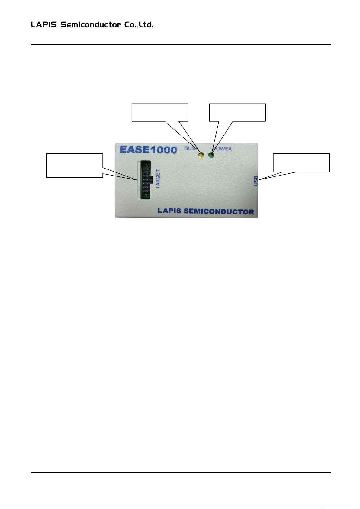
Figure 2-2 EASE1000 Components
EASE1000 User’s Manual
BUSY indicator
POWER indicator
Target interface
USB connector
Chapter 2 General Description
2.3 Appearance
The following shows the appearance diagram of EASE1000 and description of each part. In this description, a
component surrounded by brackets is the name printed on the case.
(BUSY)
(POWER)
connector
(TARGET)
Figure 2-3 EASE1000 Appearance (Top View)
- Target interfa ce connector (TARGET)
A connector to connect EASE1000 with the target system. Connect the supplied EASE1000 interface cable.
- USB connector (USB)
A connector (Type-B mini) to connect EASE1000 with the host PC. Connect the supplied USB cable.
- POWER indicator (POWER)
An LED to indicate the EASE1000 state. It lights up or blinks in green.
(USB)
FEXTEASE1000-02 3
For the relationship between the indicator light state and EASE1000 state, see "4.3 Indicator".
- BUSY indicator (BUSY)
An LED to indicate the EASE1000 state. It lights up or blinks in yellow.
For the relationship between the indicator light state and EASE1000 state, see "4.3 Indicator ".

EASE1000 User’s Manual
Terms of use for EASE1000
Parameter
Description
Power supply
USB VBUS output (5 V, 500 mA) on the host PC
Usage environment
Temperature: 5 to 40 °C
Relative humidity: 30 to 80% (no condensation)
Target LSI
Positive power supply (VTref) voltage
Target LSI operation voltage
1.6 to 5.5 V
Output power supply of EASE1000
Parameter
Description
Power supply for target LSI
(3.3VOUT)
3.3 V (typ)/100 mA (max)
Chapter 2 General Description
2.4 Terms of Use
EASE1000 should be used in an environment which meets the following conditions.
For an operating environment for software running on the host PC, see the following documents.
- DTU8 User's Manual
- MWU16 Flash Multi Writer Host Program User's Manual
When using EASE1000 as an on-chip emulator or flash writer, the power supply output from EASE1000 to the target
LSI is as follows:
The power supply for the target LSI is output after debugging with target LSI by DTU8 debugger or when
MWU16 Flash Multi Writer Host Program is in a plug state.
FEXTEASE1000-02 4

EASE1000 User’s Manual
Target System requirements
Item
Description
Interface connector
Must support the EASE1000 interface cable
(Compatible connector: HIF3FC-14PA-2.54DSA)
Target LSI
voltage
1.6 to 5.5V (Note 1)
Power consumption (VTref)
10mA
EASE1000 VTref pin power consumption (except for transient current)
Target LSI positive power supply (VDD) voltage
Power consumption (max)
+5.5V
10mA
+3.3V
2mA
Chapter 2 General Description
2.5 Target System Requirements
The target system connected with EASE1000 must meet the following requirements.
Must have a 14-pin 2.54 mm pitch connector
Positive power supply (VDD)
■Note 1■
- Since the target LSI positive power supply is used for the interna l circuit of EASE1000, its power
consumption increases when EASE1000 is in use.
Use an appropriate amount of the target syst em positive power supply whi le c onsidering the powe r
consumed by EASE1000.
- Do not connect EASE1000 when measure the consumption current of a target system.
The on-chip debugging circuit in target LSI inf l ue nc e s, and consumption curr ent increases.
The following shows the power consumption of the VTref pin used inside EASE1000.
FEXTEASE1000-02 5
EASE1000 User’s Manual
EASE1000
interface
VTref
RST_OUT/SCK
1
5
SDATA
7
3.3VOUT
13
NC
Vss
2,4,6,8,10,12
3,11,
14
~
V
DD
RESET_
N
P00/TEST0
Vss
Target LSI
VDDL
9
VDDL
~
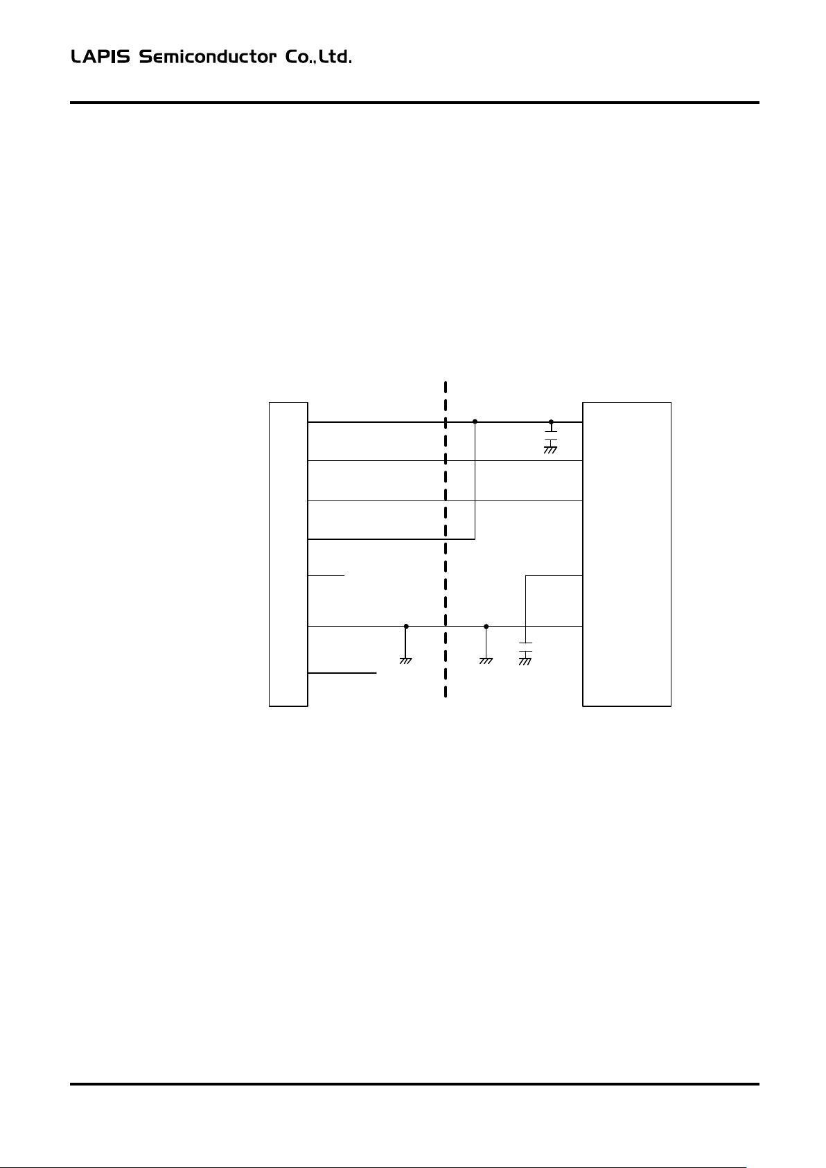
Chapter 2 General Description
2.5.1 Target System Circuit Configuration
This section describes the circuit configuration of the target system which is necessary to connect a target LSI with
EASE1000.
A pin used to connect a target LSI with EASE1000 is different depending on the specifications of the target LSI. Use
an appropriate pin according to the LSI user's manua l.
2.5.1.1 ML62Q1000 series is connected as target LSI
The example of a circuit connected with EASE1000 using RESET_N pin and P00/TEST0 pin is shown below.
FEXTEASE1000-02 6
Figure 2-4
- Do not connect the parts which RESET_N pin is fixed to a High level.
The pull-up resistance is connectable with RESET_N pin.
- When using P00/TEST0 pin, be sure to set P00 as an input mode by a application program.
If P00 is set as an output mode, it becomes impossible to use EASE1000.
Recommended circuitry using RESET_N pin and P00/TEST0 pin

EASE1000 User’s Manual
EASE1000
Interface connector
VTref
RST_OUT/SCK
1
5
SDATA
7
3.3VOUT
13
NC
Vss
2,4
,
6,8
,10,
12
3,11,14
~
V
DD
RESET_N
TEST
Vss
Target LSI
VDDL
9
VDDL
Chapter 2 General Description
2.5.1.2 ML610Q100 or ML620Q000 is connected as target LSI
2.5.1.2.1 Recommended circuitry using RESET_N pin and TEST pin
The example of a circuit connected with EASE1000 using RESET_N pin and TEST pin is shown below.
- Do not connect the parts which RESET_N pin is fixed to a High level.
The pull-up resistance is connectable with RESET_N pin.
- Do not connect any parts to TEST pin.
Figure 2-5
Recommended circuitry using RESET_N pin and TEST pin
FEXTEASE1000-02 7

EASE1000 User’s Manual
EASE1000
Interface connector
VTref
RST_OUT/SCK
1
5
SDATA
7
3.3VOUT
13
NC
Vss
2,4,6,8,10,12
3,11,14
~
V
DD
TEST1_N
TEST0
Vss
Target LSI
VDDL
9
VDDL
RESET_N
Chapter 2 General Description
2.5.1.2.2 Recommended circuitry using TEST1_N pin and TEST0 pin
The example of a circuit connected with EASE1000 using TEST1_N pin and TEST0 pin is shown below.
- Do not connect any parts to TEST1_N pin and TEST0 pin.
- EASE1000 controls reset of a target LSI, do not reset from a RESET_N pin during debugging.
Figure 2-6
Recommended circuitry using TEST1_N pin and TEST0 pin
FEXTEASE1000-02 8

EASE1000 User’s Manual
EASE1000
interface connector
VTref
1
3.3VOUT
13
NC
Vss
2,4,6,8,10,12
3,9,11,14
~
V
DD
Vss
Target LSI
When using the 3.3VOUT power supply of EASE1000, do not apply power of the target
fire.
EASE1000
interface connector
VTref
1
3.3VOUT
13
NC
Vss
2,4,6,8,10,12
3,9,11,14
~
V
DD
Vss
Target LSI
~
Power Supply
Chapter 2 General Description
2.6 Supplying Target LSI VDD
2.6.1 Supplying Target LSI VDD from EASE1000
EASE1000 has the pin (3.3VOUT) to output +3.3 V/100 mA (max) as a target LSI operation power supply.
When this power supply is used, the flash writer, on-chip debug emulator’s application program download and
software breakpoint functions are available even when the power supply voltage of the target system is set to a value
outside the flash memory opera tion voltage range of the target LSI.
2.6.1 Outputting Target System Power Supply to Target LSI VDD
The following shows a circ uit configuration example for t he case of outputting the targ et system power supply to the
target LSI V
Figure 2-7 Target System Connec tion Example (3.3VOUT Used)
Note
without using 3.3VOUT of EASE1000.
DD
system to the VDD pin of the target LSI.
If both power supplies are connected, it may damage EASE 1000 or cause an electric shock or
FEXTEASE1000-02 9
Figure 2-8 Target System Connection Example (3.3VOUT Not Used)

EASE1000 User’s Manual
1
1314
2
EASE1000
Target system
Porality slot for
EASE1000 interface cable
Pin No.
EASE1000 pin name
Description
1
VTref
Target LSI positive power supply
2
Vss
Target LSI negative power supply
3
N.C.
Unused (This should be left unconnected.)
4
Vss
Target LSI negative power supply
5
RST_OUT/SCK
Target LSI system reset signal/communication clock
6
Vss
Target LSI negative power supply
7
SDATA
Target LSI communication d a ta
8
Vss
Target LSI negative power supply
9
VDDL
Target LSI VDDL su pply
10
Vss
Target LSI negative power supply
11
N.C.
Unused (This should be left unconnected.)
12
Vss
Target LSI negative power supply
13
3.3VOUT
3.3V output pin
14
N.C
Unused (This should be left unconnected.)
Chapter 2 General Description
2.7 Target System Board La yout
The following shows a recommended board layout of the EASE1000 interface connector in the target system.
Figure 2-9 EASE1000 Interface Connector Recommended Board Layout
Also, design the pin assignment of the EASE1000 interface connector according to the following table.
Table 1 List of EASE1000 Interface Connector Pins
2.7.1 Notes of Target System Board Layout
The following shows the notes of target system board la yo ut
- The length of a cable connecting EASE1000 with the target system (EASE1000 interface cable) is approximately 15
cm. Locate the EASE1000 interface connector at the end of PCB if possible in order to make the cable between the
EASE1000 interface connector and target LSI as short as possib le.
(Compatible c onnector: HIF3FC-14PA-2.54DSA)
- It is recommended that the wiring co nnected to RST_OUT/SCK and SDAT A be shielded with Vss
FEXTEASE1000-02 10

Chapter 3 Start

EASE1000 User’s Manual
Target system
Host PC
Target LSI
EASE1000 interface cable
USB cable
EASE1000
・DTU8 Debugger
・MWU16 Flash Multi Writer
host program
Be sure to start according to the starting procedure.
electric shock or fire.
Be sure to use the cables attached to EASE 1000.
or fire.
Chapter 3 START
3 START
3.1 Starting EASE1000
This section describes how to start EASE1000.
For the following softwa re running on the host PC, see the a ppropriate user's man ual.
- DTU8 User's Manual
- MWU16 Flash Multi Writer Host Program User's Manual
3.1.1 Starting Procedure
Start EASE1000 according to the following procedure.
(1) Connect EASE1000 with the target system through the supplied EASE1000 interface cable.
(2) Connect EASE1000 with the host PC though the supplied USB cable.
EASE1000 is USB bus-powered. When the USB cable is connected to EASE1000, EASE1000 is turned on, and
the POWER indicator o n EASE1000 lights up in gr een.
(3) Turn on the target sys tem.
(4) Start the software on the host PC.
Figure 3-1 EASE1000 System Diagram
Note
Note
FEXTEASE1000-02 1
Failing to obey the procedure may damage EASE 1000 or the target system, or cause an
Using different cables may damage EASE 1000 or the target system, or cause an electric shock

EASE1000 User’s Manual
Be sure to disconnect according to the disconnecting procedure.
electric shock or fire.
Chapter 3 START
3.1.2 Removal Procedure
(1) Close the software on the host PC.
(2) Turn off the target system.
(3) Disconnect the USB cable from EASE1000.
(4) Disconnect the EASE1000 interface cable between EASE1000 and the target system.
Note
Failing to obey the procedure may damage EASE 1000 or the target system, or cause an
FEXTEASE1000-02 2

Chapter 4 FUNCTIONS

EASE1000 User’s Manual
EASE1000 state
Indicator type
Indicator light state
Idle state
POWER
On
BUSY
Off
Emulating
POWER
On
BUSY
On
Writing flash memory
POWER
On
BUSY
On
Updating firmware
POWER
Blink (Approximately 0.25-second interval)
BUSY
On
VTref abnormal voltage detection
POWER
On
BUSY
Blink (Approximately 0.5-second interval )
Device driver recognition failure
POWER
Blink (Approximately 0.5-second interval )
BUSY
Blink (Approximately 0.5-second interval )
Command execution error
POWER
Blink (Approximately 0.5-second interval )
BUSY
Off
Communication error with tar get LSI
POWER
Blink (Approximately 0.5-second interval )
BUSY
Blink (Approximately 0.5-second interval,
reversed)
Firmware binary error
POWER
Blink (Approximately 0.25-second interval)
BUSY
Blink (Approximately 0.25-second interval)
EASE1000 failure
POWER
Off
BUSY
Off
Chapter 4 FUNCTIONS
4 Functions
4.1 On-chip debug function
Connecting EASE1000 with a target LSI and using the DTU8 debugger provides the o n-chip de bug function.
・ Application program download/display/change
・ CPU status (register, F l ash memor y /Da ta me mo ry, SFR) display/change
・ Emulation (real time emulation fu nction, step emulation function)
・ Various Break
4.2 Flash writer function
Connecting EASE1000 with a target LSI and usin g t he MWU16 flash multi writer host program provides the flash
writer function.
4.3 Indicator
The indicator mounted on EASE1000 notifies of the EASE1000 status.
The following shows the relationship between the EASE1000 state and ind ic a tor light state.
Table 4-1 Relationship Table between EASE10 00 State and Indicato r Light State
The following describes the above EASE1000 states.
FEXTEASE1000-02 1

EASE1000 User’s Manual
Check if there are any problems with the connection with the target system.
Chapter 4 FUNCTIONS
Table 4-2 State e xplanation of EASE1000
Idle state Indicates the command reception waiting state from the software on the host PC
to EASE1000.
Emulating Indicates that EASE1000 is emulation state.
Writing flash memory Indicates that flash memory writing to the target LSI is in progress.
VTref abnormal voltage detection: Indicates that the voltage level o f the target LSI positive power supply (VTref) is
out of the guaranteed operation range of EASE1000.
Check if ther e are any problems with the connection with the target system or
the power supply output state.
Device driver recognition failure Indicates that installation of the EASE1000 device driver was not reco gnized on
the host PC when the USB cable was connected with EASE1000 (EASE1000 is
powered on).
Install the device driver according to the dialog box that appears on the host PC.
Command execution error Indicates that the command response from the target LSI to EASE1000 was
abnormal.
Check if there are any problems wit h the connection with the target system or
the command execution order.
Communication error with tar get LSI
Indicates that EASE1000 does not communicate with the target LSI correctly.
Firmware binary error Indicates that the data of control firmware of EASE1000 is corrupt. Update the
firmware. If the error still occurs, contact your dealer or our sales representative.
Updating firmware Indicates that the control firmware of EASE1000 is being updated. After update,
EASE1000 is automatically restarted.
EASE1000 failure Indicates that EASE1000 is broken.
Rapidly disconnect the USB cable of EASE1000 and any other external powers
from outlet. Leaving such situatio n as it might cause fire or electric shock.
If there is no problem with the connection with the target system or USB cable,
contact your dealer or our sales representative.
FEXTEASE1000-02 2

Chapter 5 Notes on Use of EASE1000

EASE1000 User’s Manual
Chapter 5 Notes on Use of EASE1000
5 Notes on Use of EASE1000
5.1 Notes on Debug
(1) About the execution cycle at the wait mode.
On wait mode, STEP execution may differ from the execution cycle of Go- execution.
The final check of an application program sho uld use Go-execution.
(2) About the RAM Match Break
・The timing of RAM Match Break is after executing a maximum of 3 instruction from the instruction which
read/write access of RAM.
・The RAM Match Break of DSR (0F000H) cannot choose.
(3) About the peripheral operation during Break
The operation of the following periphera1 stops during Break.
An interrupt request will be in a suspension s ta te and a n interrupt will generate it after an emulation start.
The periphera1 which operation stops during a break
2
- I
C mast er module
2
- I
C bus unit (master / slave)
- Serial unit (SIO / UART)
- General timer
- Functional timer
- External interrupts ( A stop of a sampling clo c k)
- Low-speed time base counter
- DMA controller
- Analog module ( CMP / DAC / AD converter / VLS)
- Buzzer
- CRC
(4) About STOP / STOP-D / HALT / HALT-D
The state of STOP / STOP-D / HALT / HALT-D will become invalid the Force break is used in the state of
STOP / STOP-D / HALT / HALT-D.
The state of STOP / STOP-D / HALT / HALT-D is canceled by break when Break-point is set up immediately
after the instruction which sets up STOP / STOP-D / HALT / HALT-D.
(5) About Real-Time-Watch
The Real-Time-Watch of DSR (0F000H) cannot choose.
(6) About change of the register value of DTU8 debugger
・W hen high-speed clock operation is chosen for target LSI, the FHWUPT register cannot be changed in the SFR
window of DTU8 debugge r..
・When following peripheral is changed by DTU8 debugger, it is set as LSI before an emulation start.
- CPU register: R0, R1, EA, PSW
- SFR: DSR, FCON
FEXTEASE1000-02 1

EASE1000 User’s Manual
Be sure to use the cables attached to EASE1000.
or fire.
Chapter 5 Notes on Use of EASE1000
(7) About the status window of execut ion time
The accuracy of Timer displayed in the status window of DTU8 is 100us units. The maximum time which can be
measured is 119 hours. If the maximum time is exceeded, a count will be continued from 0us.
The value of Timer is measured by the timer of EASE1000. Therefore, it differs from the execution time of LSI.
When a measurement period is short, an error of measurement becomes large.
Timer value = Execution time of LSI ± 0.2 % + 300us
5.2 About the 3.3VOUT pin
The specification of the 3.3VOUT pin is 3.3V/100mA.
When using the 3.3VOUT pin with the target system, do not exceed the range of specification.
Using exceeding specification, may damage the target system or EASE1000.
5.3 About Usage Environment
EASE1000 may be affected by the external environment of the host PC, USB cable, EASE1000 interface cable, and
the target system. Please check the operation in the specific customer environment before use.
5.4 About Fl a sh Writing
Confirm before using EASE1000 as a flash writer that the target LSI power supply voltage (VDD) is within t he ra nge
of the flash memory operating condition.
Also, confirm that the application program operates normally after writing.
5.5 About Cables
Be sure to use the USB cable and EASE1000 interface cable supplied as EASE1000 accessories. The operation is not
guaranteed if a cable other than the EASE1000 accessories is used.
Note
Using different cables may damage EASE1000 or the target system, or cause an electric shock
FEXTEASE1000-02 2

Chapter 6 Appendices

EASE1000 User’s Manual
Item
Description
Outside dimension
50 (W)×17(H)×90(D)[mm]
Weight
50g
Item
Description
Cable length
150[mm]
Connector form
2.54mm pitch 14 pins Two-row socket
Item
Description
Cable length
100[cm]
EASE1000 side : USB Type-B mini
Chapter 6 Appendices
6. Appendices
6.1
Form information
6.1.1 EASE1000
6.1.2 EASE1000 Interface cable
6.1.3 USB cable
Connector form host side : USB Type-A
FEXTEASE1000-02 1

EASE1000 User’s Manual
Polarity guidePolarity guide
150mm
uEASE side
Target System side
Chapter 6 Appendices
6.2 EASE1000 Interface Cable Appearance
Figure 6-1 EASE1000 Interface Cable Appearance
6.3 Update of Firmware
Please refer to the “Firmware update of EASE1000” section of “U8/U16 Development Tools release notes”.
FEXTEASE1000-02 2

Revision History

EASE1000 User’s Manual
Page
Previous
Edition
Current
Edition
FEXTEASE1000-01
September 15, 2016
-
-
First Edition
The discription about target LSI
added
Connection example to
EASE1000 is added
Connection example to
EASE1000 is added
2-8
2-10
Table1 is changed
Addition of 5.1 Notes on Debug (7)
section.
The weight of EASE1000 is
modified
Addition of 6.3 Update of Firmware
section
Revision History
Revision History
Document No. Date
FEXTEASE1000-02 December 15,2017
- 2-1
- 2-7
- 2-8
- 5-2
6-1 6-1
- 6-3
Description
can be used by EASE1000 is
FEXTEASE1000-02 1
 Loading...