

Lamina006
Lapis Drucktechnologie GmbH
Weinheimerstr. 62
68309 Mannheim
Tel.: +49(0)621/7363866
Fax.: +49(0)621/7363868
Email: info@lapis-online.de
Version: L006-S06/V3.85
Drucktechnologie GmbH
User Manual


1
3
Table of contents
1. General information...........................................................5
Product description................................................................5
Symbols and conventions....................................................... 6
Intended use........................................................................6
Safety information.................................................................6
Environmental information......................................................7
2. Connection and commissioning..........................................9
Device overview....................................................................9
Unpacking and setting up the device........................................10
Connecting the device............................................................11
Connecting to the power supply.........................................11
Connecting to a computer.................................................11
Switching on the device.........................................................11
Inserting film.......................................................................12
3. The control panel...............................................................13
Control panel configuration....................................................13
Key functions in the start menu..............................................13
Key functions in the configuration menu..................................14
Device statuses....................................................................15
4. Configuration.....................................................................17
Configuration via control panel................................................17
Configuration via interface......................................................19
Configuration: Settings............................................................21
Configuration: Device............................................................23
Configuration: System............................................................ 25
5. Control...............................................................................27
Control commands................................................................27
Status query........................................................................28
Time chart of status..............................................................30

1
4
6. Troubleshooting................................................................31
Types of errors and elimination................................................31
Error messages......................................................................32
7. Service...............................................................................35
Windows-Application: LamiControl ......................................35
Windows-Application: BootControl ......................................36
AVR programming protocol.....................................................37
8. Attachment......................................................................39
Usage of alternative foil .........................................................39
Flow control: both sides lamination with flipper ......................... 42
5
1
1
General information
Product description
Symbols and conventions
The following symbols and conventions are applied in this user manual.
The symbol indicates parts of the device that are hot and should not
be touched.
The symbol indicates important information, which must be
observed. A failure to do so may lead to injuries.
Good advice or information regarding important working steps.
Ready
Text in monospace type indicates contents on the display.
Taste
Framed text corresponds with a key on the control panel.
Robust stand-alone laminator. The Lamina006 covers all requirements of ISO
7810 plastic card applications. Quality and toughness are the highest priorities of
this laminator. A optional flipper allowing for both-sided lamination is already
integrated. Also a card feeder is available as an add-on module.

2
6
1
Intended use
The device is constructed in accordance with the latest engineering practice and
per the recognised safety regulations. Nevertheless, danger to the life and limb of
the user or third parties or damage to the device and other property may occur
when using it.
The device must be operated exclusively when in a technically faultless condition,
as intended, with an awareness of safety and potential hazards, and in accordance
with the operating manual.
The device is intended exclusively for laminating suitable materials. Any other use
or any use exceeding this is considered unintended use. The manufacturer shall
not be liable for any damage that results from misuse. The operator is solely
responsible for the resultant risk.
Safety instructions
The device is designed for an AC mains supply from 100 V to 240 V. It must be
connected exclusively to sockets with a grounded conductor contact.
The device must be operated exclusively in a dry environment and must not be
exposed to any moisture (spray, mist, etc.).
Do not operate the device in potentially explosive atmospheres.
Do not operate the device in close proximity to high voltage lines.
If the device is operated with an open cover then it is essential to ensure that
clothing, hair, jewellery and similar personal effects cannot come into contact
with the exposed, rotating parts.
The device or parts of it may become hot during lamination. Do not touch during
operation and allow to cool prior to changing the film if necessary.
Risk of crushing when locking the heated rollers or closing the cover.
Only execute the actions described in this user manual. Further work must be
carried out exclusively by trained personnel or service technicians.
Unprofessional intervention or modifications to the device may endanger
operational safety.

2
7
1
Environmental information
When opening the housing cover a risk of death exists due to live
parts.
The device comprises materials that can be reused when processed by specialist
recycling companies. The optimum design of the laminator facilitates a
straightforward separation of the recyclable materials. Label the device as scrap
and dispose of it in accordance with the legal regulations

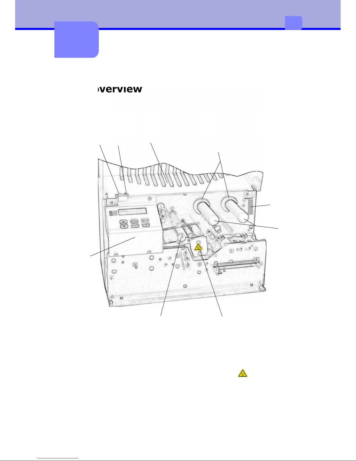
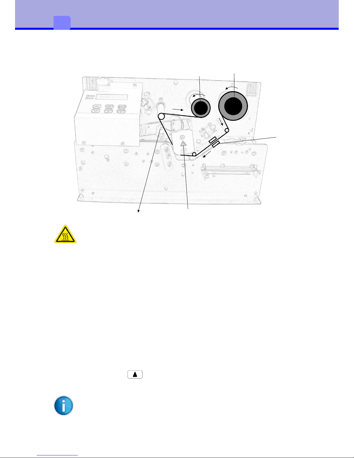
1Cover hood6Heated roller
2RFID module7Control panel
3Spacer ring8Power-LED(green)
4Carrier roller9Error-LED (red)
5Heated roller interlocking
9
2
2
Connection and
commissioning
Device overview
1
2
3
4
6
7
8
9
5

10
2
Unpacking and setting up the device
•Remove the device from its packaging and place on a level surface.
•Check the laminator for transport damage.
•Check delivery for completeness.
Scope of supply:
•Laminator
•Mains cable
Store original packaging for subsequent transportation.
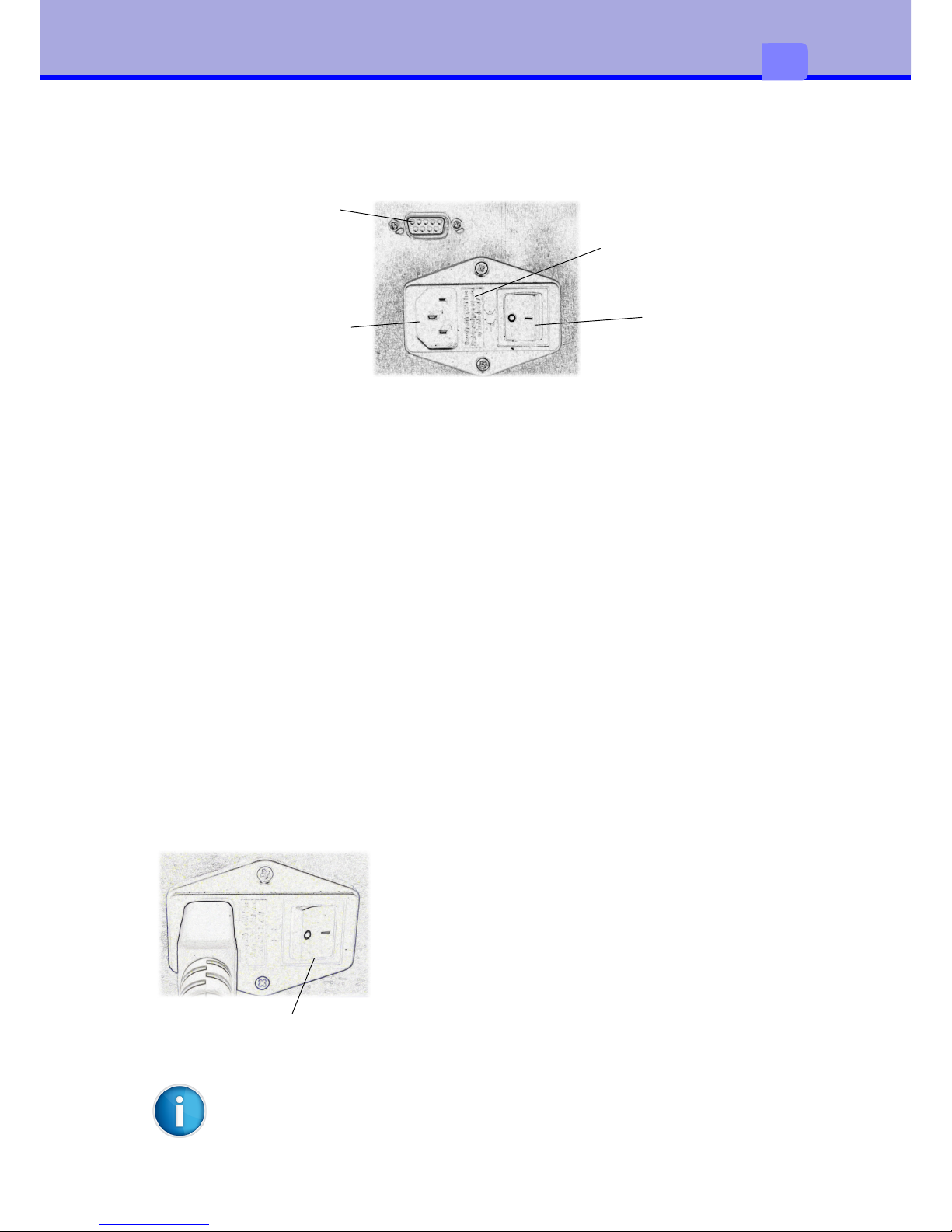
Mains switch
Mains fuse 2A slow blow
Mains connection jack
RS232-Interface
Once all connections have been established it is
possible to switch the laminator on via the mains
switch.
The device carries out initialisation with a
simultaneous self-test. If no error is present, heated
roller heating commences and the display indicates
HEATING. After roughly 8 minutes the laminator is
ready for operation and the display switches to the
Ready status.
11
2
It is assumed that film is already present inside the device.
Mains switch
Connecting the device
Connecting to the power supply
The laminator is equipped with a broad-range power pack for a mains voltage of
100 V to 240 V.
•Ensure that the device is switched off.
•Plug the mains cable into the mains connection jack.
•Plug the mains cable plug into an earthed socket
Connecting to a computer
For configuration and service purposes the laminator must be connected to the
computer with a suitable interface cable (optional).
Switching on the device
The first index mark on the film should lie before sensor (4), in order that
no patch is lost.
12
2
Inserting film
There is a risk of burning on the safety guard for the heated roller (5)
4
1
2
5
3
When inserting or exchanging patch film proceed as follows:
•
Switch off the device and let it cool down
•
Open housing cover
•
Release the heated roller interlocking. To do so push the lever (3) up.
•
When exchanging the film additionally empty carrier rollers (1,2)
•
Slide the film roll onto the unwinding carrier roller (1) until it reaches the limit
stop.
•
Slide an empty film core onto the winding carrier roller (2) until it reaches the
limit stop.
•
Insert the film in accordance with the drawing shown above. Attach the start
of the film to the empty core with adhesive tape.
•
Close the heated roller interlocking. To do so push the lever (3) down.
•
Switch on the device.
•
Transport film with to the first patch and when doing so check that the
film runs correctly and crease-free.
13
3
3
The control panel
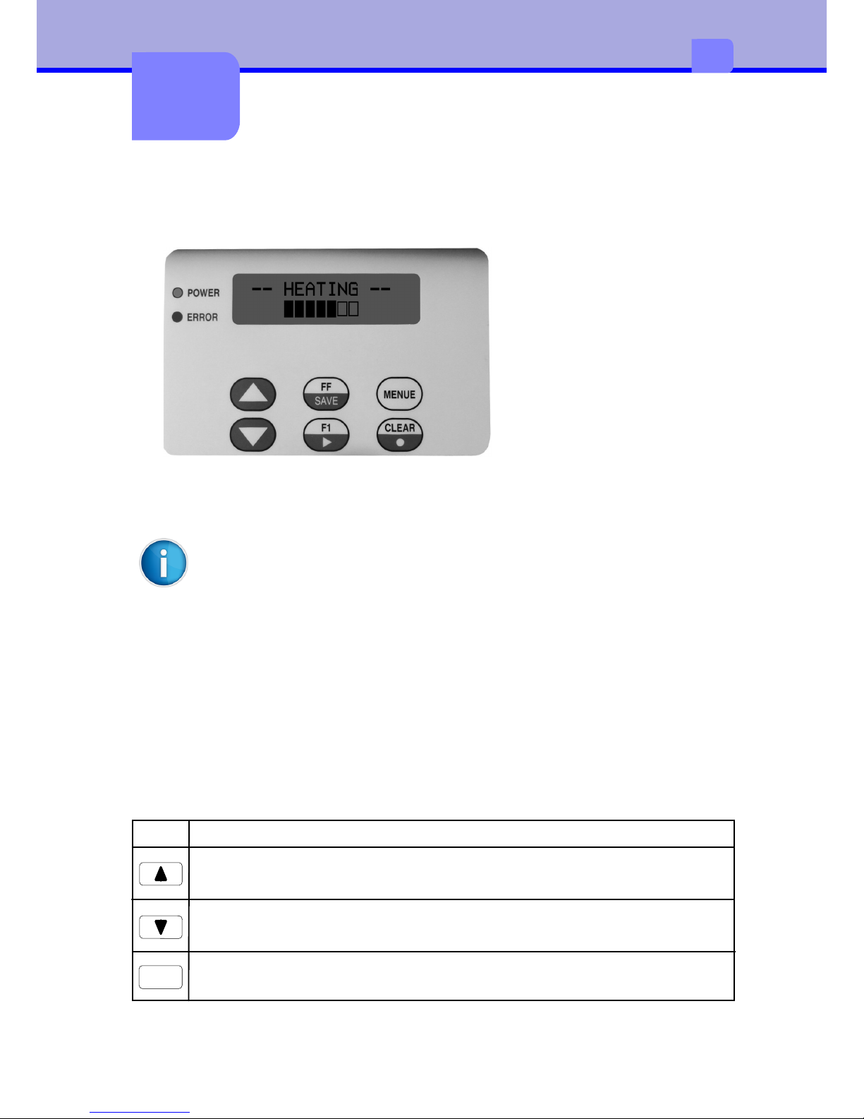
Control panel configuration
The display informs the
user of the current device
status, reports errors and
indicates configuration
settings in the menu.
The keys enable control
functions, the accessing of
information and navigation
within the menu.
If the device is switched on then the green LED illuminates. An error is
additionally signalled via the red LED.
The control panel can be folded out for improved ease of operation and
legibility. To do this draw the black button on the bottom edge of the
control panel forwards
The functionality of the control panel differs in the start menu and the
configuration menu.
Key functions in the start menu
The start menu contains all functions on one level, making these directly
accessible. Key navigation is not required. During lamination the buttons are
locked.
KeyFunction
Transports the film forwards. Useful when inserting new film
Transports the film backwards. Useful when inserting new film
FF
Transports a document manually from the tray

14
3
TasteFunktion
Displays the device no. and program version
Switches to the configuration menu
F1
CLEAR
Deletes error messages
MENUE
Key functions in the configuration menu
The configuration menu offers setting options across multiple levels, in order to
configure the laminator for the specific requirements. It is also equipped with test
and service functions in order to support the configuration and function of the
device. During lamination the buttons are locked.
TasteFunktion
Start the configuration menu
Scrolls forwards within the respective menu level. At access level
changes or reduces the value.
MENUE
Scrolls forwards within the respective menu level. At access level
changes or reduces the value.
One menu level up
SAVE
Scrolls forwards within the respective menu level. At access level
changes or reduces the value.
One menu level down

ZustandBeschreibung
The laminator is ready for operationt
Ready
-- HEATING --
The laminator is in the heat-up phase
-- COOLING --
The laminator is in the cool-down phase
in process
The laminator is ready for operation
Initialization
After the switch-on process the laminator is in the
initialisation phase and carrying out the self-test
STANDBY
If the laminator is not used for 30 minutes it switches
to energy-saving mode. The temperature of the
heated roller drops in this mode.
Press to end.
The energy-saving mode must be activated in the
menu!
#64 retract
An error is displayed, for example #64
CLEAR
15
3
Feeder empty
Stack of card in feeder is empty
Device statuses


17
4
4
Configuration
Configuration via control panel
1. Menu level 2. Menu level Access level
Startmenü
SETTING
DEVICE
SETUP
FoilType
Standby
Loop
Index=Yes
No
No
The different setting options configure the laminator for specific requirements. This
is carried out either via the control panel or via the interface by means of a
command set. There are exceptions, whereby access is only possible via one or the
other method.
Simultaneous switching on of the device and pressing of the key
resets all settings to the standard values. The setup values are an
exception to this.
CLEAR

SETTING
Temperature150 ºC
Lamination Speed 6 mm/sTest
Delay Heatroller200 ms
Transport Speed 80 mm/sTest
LaminationLength 86 mm
FoilFurtherMove 14 mm
Foil Position 0 x1/10mm
DEVICE
Foil CategoryNormal Foil
Foil TypePATCH
StandbyNo
FeederNo
double-sidedNo
Operation ModeNormal
18
4
1. Menu level2. Menu levelAccess level
= Default value
Special function
on Access level
Menu structure
Farther settings are possible by the Windows tool.
Within the access level the user works in editing mode:
KeyFunction
Increases / reduces the value or changes an option
Exits the editing mode. Changes are lost after the device is switched
off.
Exits the editing mode. Changes are retained after the device is
switched off.
SAVE
Special functions for some parameters

19
4
Configuration via interface
The parameters accessible via the control panel can also be adjusted via the serial
interface. Furthermore, there is an additional command for controlling the device.
The laminator is connected by means of a standard cable
RS-232 SERIAL SUB D9 connector jack
to the computer.
Die RS232-Parameter:
Baudrate19200
Databits8
Paritynone
Stopbits1
The sequences for the command transfer are constructed as follows:
<ESC> cmd [data] <CR>
A few communication rules:
•<LF> is ignored
•Every command transfer is acknowledged with <CR>
•Sequences without parameter data deliver the actual value (ReadBack)
•No data is sent back when not requested
Italic characters in the command description are placeholders and must be
replaced:
•d = Decimal number
•p = Boolean number: 0 oder 1 (1 Byte)
•h = Hexadecimal number: 1-9, A-F, a-f (1 Byte)
•c = Arbitrary character:0-9,A-Z,a-z(1 Byte)
•s = Arbitrary string:...
•<...> = Control caracter as <ESC> or <CR>
•Boldprinted Character are directly be taken on.
•Underline refers to default setting
Example:Send:Response:
<ESC>T175<CR><CR>
<ESC>T<CR>175<CR>

SETTING COMMANDS
DdDelay Heatroller
GdLamination Speed
HdTransport Speed
LdLamination Length
NdFoil Further Move
PdFoil Position
TdTemperature
DEVICE COMMANDS
K01;pFoil Type
K02;pSkip lamination
K04;pDouble-sided (only with optional flipper)
K10;pFeeder
K20;pFoil Synchronisation (with / without index bar)
K40;pStandby
K80;pFoil Category (normal / alternative)
CONTROL COMMANDS
!!Reset
!cClear Error
!rAlife-Status
!RRibbon-Status
!fStatus
RBnext card with both sides laminating (only with optional flipper)
RCnext card starts cleaning procedure
RNnext patch (only for tests)
RSnext patch synchronization (only for tests)
SYSTEM COMMANDS
!vRead Programm-Version
y8aRead Serial Number (Board)
y8bRead Serial Number (Device)
y5Read Tag-Info
S Save Macro
20
4
List of Commands

21
4
Configuration: Settings
Menu: SETTING / Temperature
Command:<ESC>Td<CR>
Setting the thermal energy for the heated roller for lamination. The correct
temperature must be experimentally determined with consideration to the
lamination speed, the film and the plastic card. The presetting must be considered
a guideline value.
Setting range(d):120...150...180 degree C
Menu: SETTING / Lamination Speed
Command:<ESC>Gd<CR>
Setting of the transport speed of the document during lamination. The correct
speed must be experimentally determined with consideration to the lamination
temperature, the laminate film and the plastic card. The presetting must be
considered a guideline value.
In order to carry out a test it is possible to start the motor via
Setting range(d):4...6...20 mm/s
Menu: SETTING / Delay Heatroller
Command:<ESC>Dd<CR>
Setting the waiting time, once the heated roller has lowered and lies on the
document. Only after this time does the actual lamination start.
Setting range(d):0...200...2000 ms
Menu: SETTING / Transport Speed
Command:<ESC>Hd<CR>
Setting the transport speed of the plastic card outside of lamination. In order to
carry out a test it is possible to start the motor via .
Setting range(d):40...60...80 mm/s

22
4
Menu: SETTING / Lamination Length
Command:<ESC>Ld<CR>
Setting the lamination range.
Setting range(d):80...86...100 mm
Menu: SETTING / Foil Position
Command:<ESC>Pd<CR>
With a change in the plastic card intake range, precise placement of the film is
carried out.
With an enlarging of the intake range, the lamination of the plastic card starts
later. Conversely, with a reduction in the intake range lamination starts earlier.
The direction arrows on the display indicate the direction of travel once lamination
starts.
Setting range(d):-30...0...+30 x 1/10mm

Menu: DEVICE / Foil Type
Command:<ESC>K01;p<CR> und <ESC>K20;p<CR>
Setting the film type.
Setting range: p p
K01 = 1, K20 = 1: Patch (allways with Index)
K01 = 0, K20 = 1: Hologram with Index
K01 = 0, K20 = 0: Hologram without Index
23
4
The difference between patch and thin film with/without black marking is another
lamination position of the card.
Menu: DEVICE / Operation Mode
Command:<ESC>K02;p<CR>
The laminator operates in 3 different modes. 1 of these is exclusively suitable for
test purposes only in menu.
Setting range:p
0 = Normal
1 = Skip lamination
Test: Normal Hoff
3 = Front lamination, if alternative foil
4 = Back lamination, if alternative foi
The standard setting is "normal" and reflects normal operation.
With the setting "Skip lamination" the plastic card is not laminated. Heating is on
without WAIT-Status.
"Test: Hoff" also reflects the normal operating process, but the heating is off in
this case.
Menu: DEVICE / double-sided (only with optional flipper)
Command:<ESC>K04;p<CR>(only with optional flipper)
Cards are laminated on both sides. In addition the optional flipper is required.
Setting range:0 = double-sided inactive
1 = double-sided active
Configuration: Device

24
4
Menu: DEVICE / Feeder
Command:<ESC>K10;p<CR>
An optional feeder with stack could be connected.
Setting range:p
0 = without feeder
1 = with feeder
Menu: DEVICE / Standby
Command:<ESC>K40;p<CR>
If the laminator is not used for 30 minutes it switches to energy-saving mode.
The temperature of the heated roller drops in this mode. Press to finish.
The energy-saving mode must be active for this!
Setting range:p
0 = Standby off
1 = Standby on
CLEAR
Command:<ESC>K80;p<CR>
Change foil category. The “Alternative foil”-Option only makes sense in
connection with front- and back-lamination commands (K02;3 and K02;4).
Setting range:0 = Normal foil
1 = Alternative foil

25
4
Function:Read Programm-Version
Startmenu:
Command:<ESC>!v<CR>
Reads the firmware version. Is shown in line 1 on the display.
As a response following a command transfer the user receives a sequence in the
form e.g. "LAMI-S06/V3.30<CR>
F1
Function:Read Serial Number (Board)
Command:<ESC>y8a<CR>
Reads the serial number of board.
As a response following a command transfer the user receives a sequence in the
form e.g. "PL13091570B06RL<CR
Function:Read Serial Number (Device)
Startmenu:
Command:<ESC>y8b<CR>
Reads the serial number of device. Is shown in line 2 on the display.
As a response following a command transfer the user receives a sequence in the
form e.g. "PL13091570M02RL<CR>
F1
Function:Tag-Info
Command:<ESC>y5<CR>
Reads the 8-digit tag information.
As a response following a command transfer the user receives a sequence in the
form e.g. "12345678<CR>
Function:Storage of Macro
Menu:
Command:<ESC>S<CR>
All configuration parameters are stored in the EEPROM so that these values are
not lost after the switch-off process. When switching on the laminator the stored
settings are reloaded and reused.
The command sequence is acknowledged with “+”.
Configuration: System


27
5
5
Control
Control commands
Reset
Command:<ESC>!!<CR>
The laminator is reset. The process equates to a restart after a Power On.
Settings that are not saved in the macro are lost.
Function:Clear Error
Startmenu:
Command:<ESC>!c<CR>
Deletes error messages, refer also to the "trouble-shooting" chapter.
CLEAR
Function:Both sides lamination(only with optional flipper)
Command:<ESC>RB<CR>
For both sides lamination, send this command for each card before input to the
laminator. This command is only executable if flipper is connected.
Function:next patch
Command:<ESC>RN<CR>
Foil-Transport to the next patch without reading ribbon status. Only for tests!
Function:next patch synchronization
Command:<ESC>RS<CR>
Foil-Transport to the next patch with reading and setting ribbon status. It can get
lost up to 2 patches. Only for tests!
Function:Cleaning
Command:<ESC>RC<CR>
Next card starts the cleaning procedure without foil and temperature.

28
5
Status query
Function:Status
Command:<ESC>!f<CR>
Delivers detailed information on the current status of the laminator. The status
can be requested at any time.
The response consists of 7 Bytes.
Format: =hh/dd<CR>
hh: Statuscode Hint:
00: READYDevice is ready for work
01: WAITTemperature of heat roller too high / too low
02: BUSYLaminator is active
04: ERRORErrorcode is setting
10: GOT ITDocument identified to start lamination
20: LAMILamination od Document activ
40: EJECTEjection of Document activ
dd: ErrorcodeHint
00no Error
ddErrorcode, see chapter “Trouble shooting”
Status bits also occur in combination. E.g. status code “42” means that the
laminator is active and is presently outputting a document.
Function:Alife-Status
Command:<ESC>!r<CR>
Delivers information on the current status of the laminator. The status can be
requested at any time.
The response only consists of 2 Bytes.
Format: d<CR>
d: Statuscode Hint
0 = OKDevice is ready for work
1 = WAITTemperature of heat roller too high / too low
2 = BUSYLaminator is active
4 = ERRORErrorcode is setting

29
Function:Ribbon-Status
Command:<ESC>!R<CR>
Delivers information on the current status of the ribbon side. The status can be
requested at any time.
The ribbon status will be refresh after RS-command and after start of laminating.
The response only consists of 3 Bytes.
Format: <ESC>d<CR>
d: Statuscode
0 = unknown
1 = next patch is recto
2 = next patch is verso
3 = busy
5

30
5
Time chart of status
Eject backside to the exit stacker
Sensor LS1
Sensor LS2
Sensor LS3
GOTIT
BUSY
LAMI
EJECT
heatroller downheatroller up
entrancelaminationeject

31
6
6
Troubleshooting
Types of errors and elimination
If an error occurs then this is signalled by the red ERROR LED whilst the error
message is shown on the display. Different error codes indicate the cause of the
problem. In a normal case it is possible to delete the error message after
eliminating the problem with after which the device is once again ready for
operation.
CLEAR
StatusLEDDisplay
Rectifiable errorsblinkserrorcode < #80
Non rectifiable errorsonerrorcode > #80
System errorsonerrorcode > #90
"Rectifiable errors" are usually film or transport errors, which are simple to
remedy.
"Non-rectifiable errors" are triggered by defective hardware. If a restart does not
solve the problem then service intervention is necessary.
In the event of a "system error" the device must be returned to the factory.
#61 card inside
As an alternative to the control panel it is also possible to query the error code via
the status message and delete this via the Clear command.

32
6
Error messages
Error messageCause Remedy
#53 Tag invalid
Invalid tag information with
initial acquisition of the film.
Use permissible / approved film
material.
#54 RFID ERR=dd
Reader:Communication Error
dd=24 read err
dd=83 write err
Error message from tag reader.
Indicates signal between reader
and tag too weak. Visual
inspection!
#55 RFID CRC
Reader transfer error.
Contact problems between
board and tag reader
Check connection cable (service)
#56 RFID MSG
No response from tag
reader. Tag not seen or not
read.
Use permissible / approved film
material.
#61 card inside
Document located in the
transport tray after restart or
after and could not be
ejected
Remove document from the
transport tray manually.
CLEAR
#62 eject
Ejection of the document
failed.
Remove document from the
transport tray manually.
#63 transport
Transport of the document
failed.
Remove document from the
transport tray manually.
#64 retract
Intake of the document
failed.
Remove document from the
transport tray manually.
#65 ribbon end
Film end
Insert new film
#30 Standby
#31 Feeder empty
Feeder is empty
Insert cards to feeder and press
clear or send clear command.
Laminator is switched to the
energy saving mode.
Press Clear or send a Clear-
Command to end.

33
6
#81 RFID no data
No response from tag reader. Check tag reader.
Contact service!
#82 ADC problem
Impermissible ADU values
Check temperature sensor.
Contact service!
#83 ADC problem
No temperature increase to
record
Check temperature sensor.
Contact service
#84 heat roller
Heated roller not in limit
position
Contact service!
#85 heating
Circuit breaker for high
temperature has triggered.
Contact service!
#86 Sensor ???
Both sensors in transport tray
see document
Check transport tray, otherwise
Contact service!
#98 EEPROM/SETUP
No access to the EEPROM
Contact service!
#99 Call Service
Electronic type plate missing Contact service!
Error messageCause Remedy
#87 Flipper
Flipper in wrong position
Check if card in flipper. If not,
contact service!
#66 ribbon synch
Synchronisation of the film
failed.
- Insert film with index marks
- Insert film correctly
- Configure correct film type
#67 ribbon trans
No film transport.
Check film
#71 Foil category
Foil category could not be
read
Press Clear or send a Clear-
Command to end. After this:
Category = normal


Service
35
7
7
Windows-Application: LamiControl
Use this tool for tests and configuration of the L006 laminator. Y
ou also can use
the LamiControl-Tool for downloading the newest manual, application and firmware
with programming. For some settings you need a password.

36
7
After starting the Windows application BootControl it is possible to load new
firmware. Prior to this the interface agreements as well as the path for the access
to the application code (*.HEX) must be stipulated
The download process normally can be started as follows:
•Switch on laminator
•Press „Starting firmware update“
If anything goes wrong and the update-process cannot started, you need the
service-panel and started as follows:
•Switch on laminator and simultaneously hold the key down
•Press „Starting firmware update“
For service purposes the laminator is connected with the computer via the serial
interface. A standard cable RS-232 SERIAL SUB D9 connector jack is used.
Alternative, you also can use the LamiControl-Tool for downloading the newest
firmware and programming.
Windows-Application: BootControl
F1

After the AVBRL is started (via a reset, a power-up, or a jump from the main
application), the following protocol must be observed:
1. Upon power-up, reset, or as a result of a jump from the main application, the
AVRBL sends a ‘^’ (BOOTLOADER_ACTIVE_CHAR) at your selected baud
rate.
2. The host is then required to send the three-character entry sequence. This is
used to prevent an inadvertent attempt of reprogramming from taking place. If
the AVRBL does not receive these characters within the timeout period, the
AVRBL tests to see if there is code located in the main application area of flash.
If there is, then the AVRBL jumps to it, otherwise, execution stays within the
AVRBL indefinitely, waiting for the entry sequence.
3. Once the three-character entry sequence has been sent, the bootloader sends
the version string (Vx.xx) followed by a ‘?’ (READY_CHAR).
4. Upon receipt of the READY_CHAR, the host application should send the hex file
for the new/updated application program observing an X-ON / X_OFF
handshaking protocol to control data flow. The handshaking is very important as
the flash memory area writes much more slowly than the serial port can send
data.
37
7
The upgrade process can also be started without Windows software via the
sequence <ESC>U<CR>. The subsequent protocol must then be carried out
independently:
LaminatorHostHint
ˆBootLoader is ready
@&$Start Download Sequence
V1.31
?ready for Download
XONenable Interface
:naatddd…cSend 1 HexLine (Intel-Hex-Format)
-if Checksum Error
XOFFdisable interface
%if Verify-Error in Flash-Page
~HexLine closed
#EOF identified, exit with error
@EOF identified, exit without error
AVR Programming Protocol

The programming software continues sending the hex file until it is all sent. After
each line of “.hex” file is received by the bootloader, one of three characters is
transmitted by the bootloader:
- ‘~’ Line received with no errors.
- ‘%’Line received with no error, but an error occurred while flashing.
- ‘-‘ Checksum error detected while receiving the line.
5. After the programming is complete, the AVRBL sends either a ‘#’, meaning the
programming is all right, or an ‘@’ indicating that an error has occurred and the
program did not load successfully. In most cases an error during programming
means that the main application program is corrupted and will need to be resent.
6. The AVRBL then starts the newly programmed application software. As stated
in step 2, the AVRBL tests to see if there is code located in the main application
area of flash. If there is, the AVRBL jumps to it, otherwise, execution stays within
the AVRBL indefinitely, waiting for the entry sequence.
Character Definition
//define three character string to enter boot loader
#define char1 '@' /* reset codes.. start load codes.. */
#define char2 '&'
#define char3 '$'
// define bootloader active char
#define BOOTLOADER_ACTIVE_CHAR '^'
//define bootloader ready for file character
#define READY_CHAR '?'
// define line complete with no error character
#define LINE_COMPLETE_CHAR '~'
// define checksum error character
#define CS_ERROR_CHAR '-'
// define flash page error character
#define PAGE_ERROR_CHAR '%'
// define file complete, no errors character
#define FILE_COMPLETE_CHAR '@'
38
7

Usage of alternative foil
39
8
Attachment
8
With the usage of alternative foil a patch is in each case for card-front and
card-back in alternate order intended. For the Laminator it is important for the
synchronisation of the foil to know whether it concerns a normal or an alternative
foil (foil category). The real foil transport takes place always directly before the
lamination. At that time must be confessed by a suitable command in which
manner the positioning has to take place not to synchronise normally on the
following patch.
The category of the foil is read normally always after Power On about the RFID
information. Besides, a short foil transport can originate. If one wants to avoid
this or one works in general without RFID, one can suppress the automatic
capture in the menu (optional display or windows tool). Besides, the manually
definition of the category occurs again about the menu or also by command.
menu
PowerOn
Manual
registration
Automatic
registration
K80;0
Change
category
K80;1
command
Normal
Alternative
or
foil-category

The following commands are important for the handling with alternative foil:
Foil category - normal foil: <esc>K80;0<cr>
Only makes sense if the definition of the foil category from should occur
externally. This is also the standard default, if none automatic recognition was
possible. Besides, is always synchronised on the following patch, even so if an
alternative foil is inserted. Front- and back-command have no influence.
Foil category - alternative foil: <esc>K80;1<cr>
Only makes sense if the definition of the foil category from should occur
externally. Front- and back-command have influence on the foil synchronisation.
Synchronization: <esc>K02;0<cr>
Regardless of the foil category it is always synchronised on the next patch. This
is also the standard default.
Synchronization: <esc>K02;3<cr>
The next synchronisation starts from a front patch with followed change,
provided that an alternative patch foil is inserted. With the first synchronization
patches can be jumped over, if the ribbon status is still unknown.
Synchronisation: <esc>K02;4<cr>
The next synchronisation starts from a back-patch with followed change,
provided that an alternative patch foil is inserted. With the first synchronisation
patches can be jumped over, if the ribbon status is still unknown.
40
8

Ribbon-Status: <esc>!R<cr>
The ribbon status always indicates the position of the following patches. If the
information is not available, a foil transport occurs before the synchronisation up
to the reading. This is after a new start basically the case.
0 = unknown
1 = next patch is front
2 = next patch is back
3 = busy
Command
K02,0
K02,3
K02,4
to next patch
foil category
Normal
Alternative
K02,0 error
K02,3
K02,4
to next front patch
to next back patch
Synchronization
41
8

Flow control: both sides lamination with flipper
Ribbon-Status: <esc>RB<cr>
The following card is laminated in the laminator on both sides. The command
must be sent renewed for every card.
After the first lamination the card is turned in the flipper and is supplied to the
laminator once more. After the second lamination the card about the flipper is
ejected.
Foil category = “normal”:
It is laminated on both sides and, besides, synchronized always on the following
patch.
foil category = “alternative”:
It is laminated on both sides. Besides, the foil is synchronized first on the front-
sided and afterwards on the back-sided patch. Above the front-/ back-command
can be changed the start condition.
start lamination
Designating “both sides lamination”
Starting with “front-side”
Creating Command: RB
Retracting card to LXS
Waiting for LXS job done (BUSY = 0)
finish
front- and back-side
lamination
Designating front- or back-side
lamination
Creating Command: K02;3 or K02;4
optional
42
8
 Loading...