

Page 1

LAPCOM S SERIES
GPS RECEIVER
Instruction Manual
PERCUL CORPORATION
Page 2
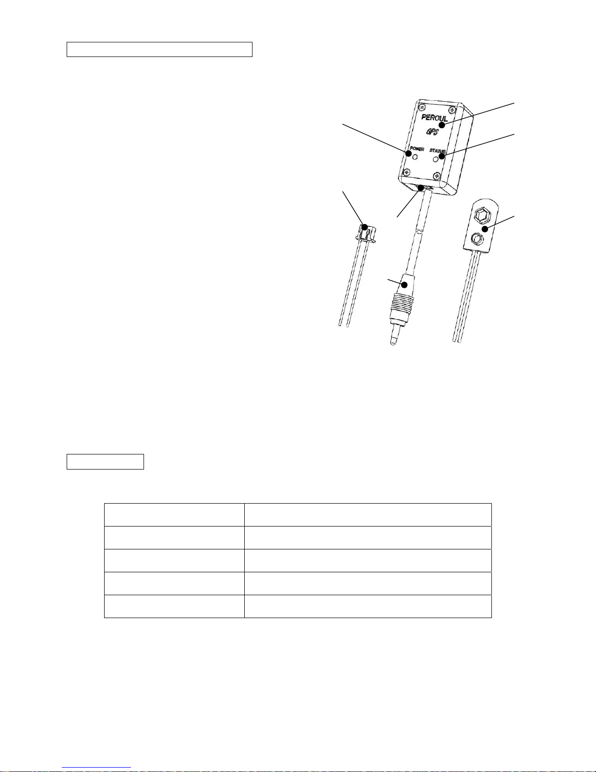
Names of Parts of GPS receiver
1. Built-in GPS antenna
1
2 3 4
5
6 7
GPS antenna is inside.
2. Power lamp(Blue)
The lamp illuminates when the power is
on.
3. Status lamp(Red)
The lamp illuminates or flashes when
receiving information from the satellite.
4. Power port
Insert the power connector.
5. Communication cable
Connected to the COM port of Lapcom
unit.
6. Battery snap
Used for 9V square type battery.
7. Power connector
Connect to 12V power or 9V square type battery on the other side, and insert to
the power port of the GPS receiver.
Specification
Size 50x30x20 mm
Available voltage DC7.5 to DC14.5V
Consumption current 10mA
Hot start 1.0 sec
Cold start 35 sec
-1-
Page 3
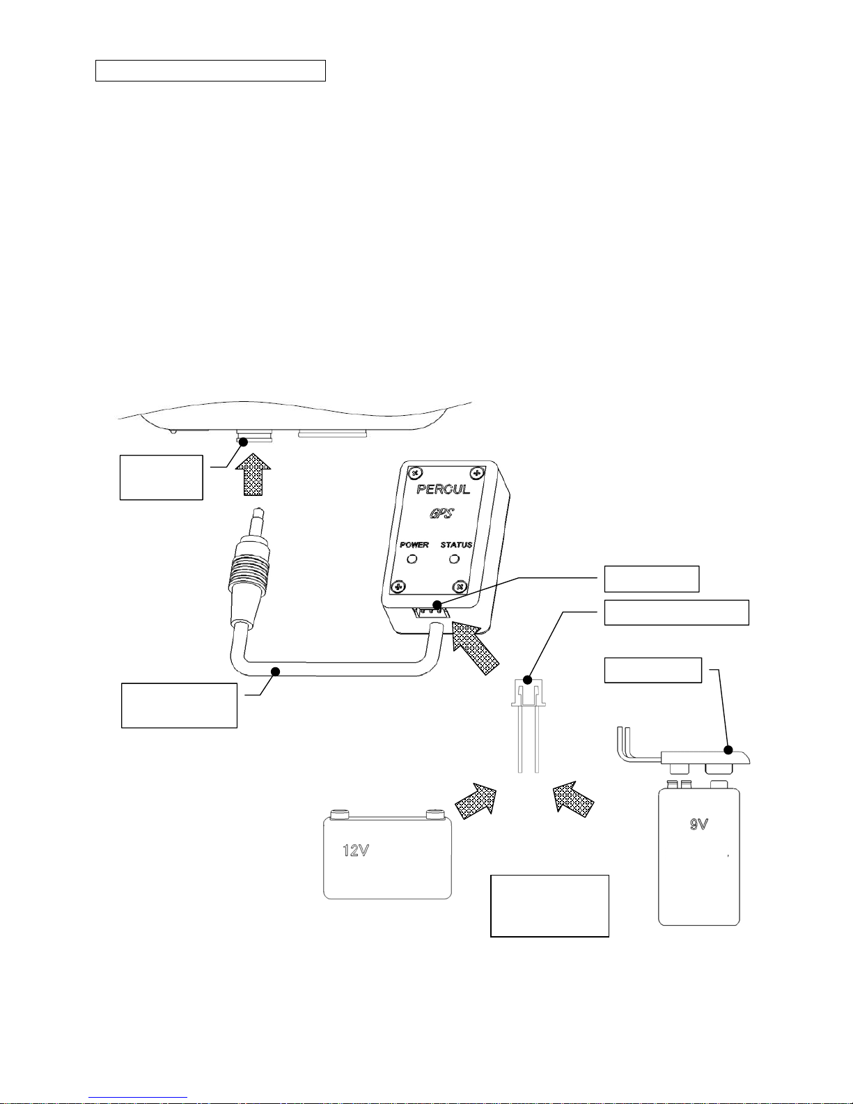
How to install GPS receiver
1. Put the top side with logo horizontally toward the sky on the location where the
signal from the satellite can be received well.
2. Connect to 12V power battery or 9V square type battery on the other side of the
power connector, and insert the connector to the power port of the receiver.
* The power connector’s red line is into the plus(+) of the 12V power battery or
9v square battery, the black line is into the minus(-).
* Available voltage is DC7.5V to DC14.5V.
3. Connect the communication cable to the Lapcom COM port.
LAPCOM
COM port
Use 12V powe
r
or 9V square
type battery
Power port
Power connecto
r
Communication
cable
battery
square
type
battery
Red (+)
Black (-)
Battery snap
-2-
Page 4
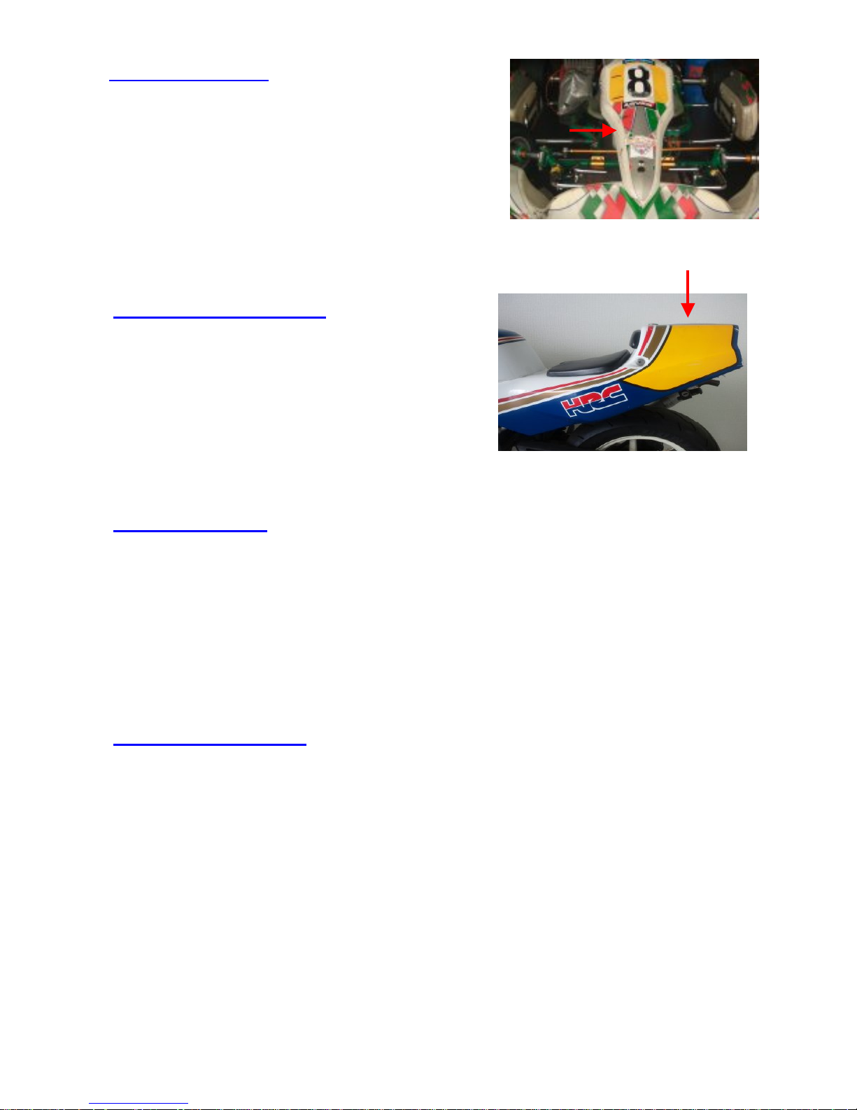
Installation for kart
Attach the GPS receiver’s top side with logo
horizontally toward the sky on the front panel by
two-sided tape or hook & loop fastener. Please
provide the installation bracket as per your
requirement.
Installation for motorbike
Attach the GPS receiver’s top side with logo
horizontally toward the sky on the rear cowling
by two-sided tape or hook & loop fastener.
Installation for car
Attach the GPS receiver’s top side with logo horizontally toward the sky on the
dashboard by two-sided tape or hook & loop fastener. Some kinds of windscreens
including heat-reflecting glass would be difficult to acquire the GPS satellite. In
that case, please attach on the roof.
Caution for installation
- To avoid the noise from the engine ignition, put the receiver away from the
engine, and do not fix the GPS receiver's cable together with other sensors'
cables.
- If the GPS receiver is subjected to strong vibration, malfunction may occur.
Place low-repulsion urethane (sponge or similar) around the sensor to absorb
vibration.
- If using the GPS receiver in the rain, wrap it with plastic bags so as not the
receiver and cables wet.
-3-
Page 5
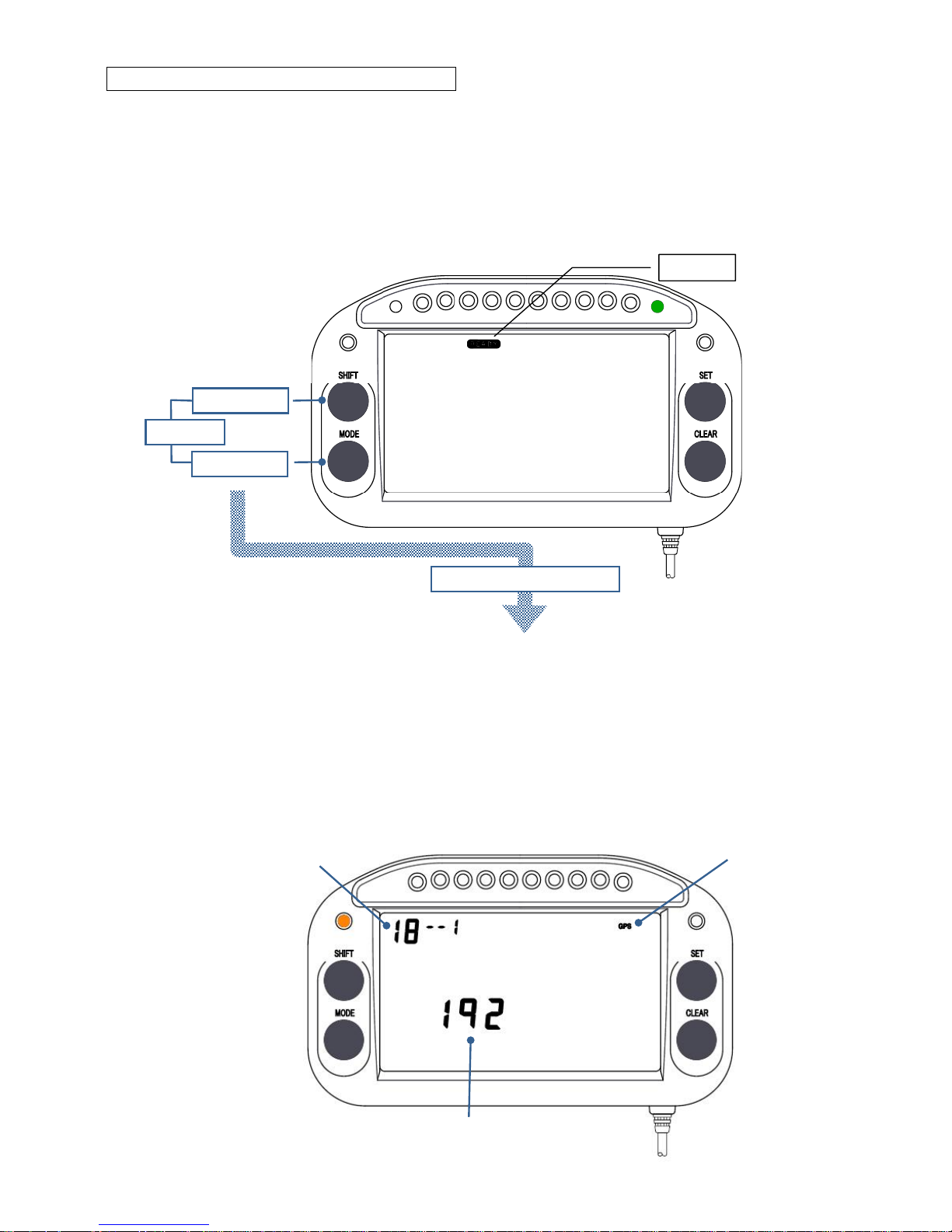
Parameter setting of the Lapcom unit
Set the communication speed between GPS receiver and Lapcom unit.
1. Verify that [READY] is displayed on the display screen. If [READY] is not
displayed, press the CLEAR key to display it.
2. Press and hold the SHIFT key and MODE key at the same time for 3
seconds to change to the parameter setting screen. The parameter number
is displayed at the top left of the display.
READY
To the parameter setting
SHIFTキー
MODEキー
+
MODE key
SHIFT key
3 seconds
3. Press the CLEAR key and display parameter No. 18.
4. There is a flashing hyphen or number on the right side of the parameter No.
Press the SET key and enter “1” to display [GPS].
5. Press the SHIFT key and move the flashing digit to the baud rate, then press
the SET key and select “192(19200bps)”.
6. Press the CLEAR key to move to the next parameter setting. To exit the
setting, press and hold the CLEAR key for 3 seconds.
[GPS] display
Baud rate
Parameter No.
-4-
Page 6
7. Confirm the following parameter setting to log the driving data properly. Press
and hold the CLEAR key for 3 seconds to exit the setting.
Parameter No. 3: Number of Segments
Parameter No. 4: Sensor Off Timer
Parameter No. 5: Speed Pulse Length
Parameter No. 7: Logging start/stop condition
* Please refer to each model’s instruction manual for the parameter
setting.
* It is necessary to measure speed.
8. Insert a SD card into the Lapcom main unit, and confirm the SD card mark is
shown on the display.
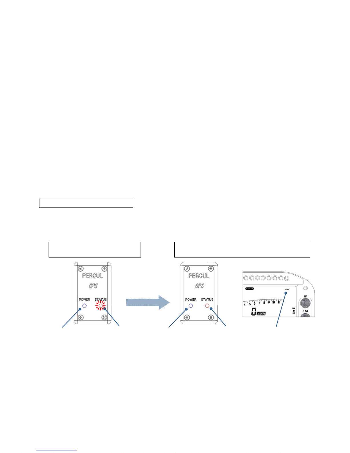
LED and Display indication
LED and the display indication of each status are as follows;
Acquiring GPS satellite Completed GPS satellite acquisition
POWER (Blue)
illuminate
STATUS (Red)
flash
POWER (Blue)
illuminate
STATUS (Red)
illuminate
GPS or DGPS
illuminate
-5-
Page 7

NOTICE POINTS
COLD START:
The first start after purchasing the GPS receiver, or the start after remaining
unused for a long period.
Please notice COLD START will take longer time to acquire the GPS satellite, like
about 35 seconds.
Turn on the power of the device 15-30 minutes before driviing in a open place to the
sky.
Please notice that aquiring the GPS satellite would be difficult in the following place;
- In doors or behind a building
- Between tall buildings
- Near the object that generates magnetism like high-voltage electrical power lines
- On the narrow road between dense trees or buildings
- When operating the GPS receiver through heat reflecting glass
To acquire the GPS satellite properly
- Acquire the GPS satellite in a open place to the sky.
- Keep the receiver’s top side with logo horizontally toward the sky.
- Do not move the place 15 to 30 minutes until completing the acquisition.
-6-
 Loading...