

Page 1
ⓒ2016 LaON Technology Co., Ltd. All rights reserved.
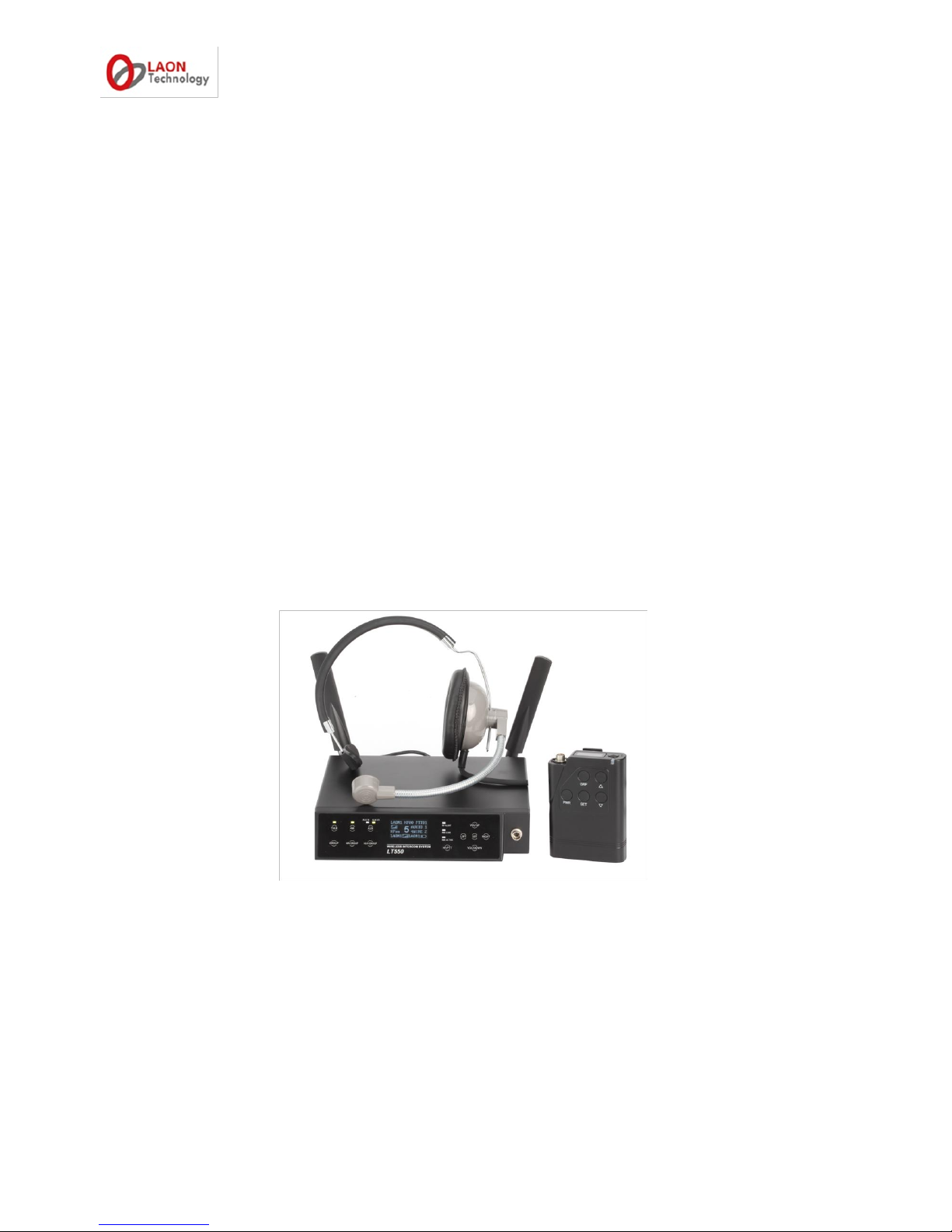
LT550 EXPERT
Digital Wireless Intercom System
Operating Instructions
(V2.6 160501)
LaON Technology Co., Ltd.
Page 2

ⓒ2016 LaON Technology Co., Ltd. All rights reserved.
TABLE OF CONTENTS
IMPORTANT SAFETY INFORMATIONS
3 SECTION 1. INTRODUCTION
5
SYSTEM USAGE EXAMPLE
7 SECTION 2. PRODUCT OVERVIEW
10
BS550 BASE STATION EQUIPMENTS
10
BP550 BELT PACK EQUIPMENTS
11
BATTERY CHARGER AND HEDSET EQUIPMENTS
11
REMOTE BASE STATION EQUIPMENTS
13
EQUIPMENTS OVERVIEW
14
BS550 BASE STATION OVERVIEW
14
BP550 BELT PACK OVERVIEW
15
BASE STATION MENU
16
BELT PACK MENU
17
SECTION3. SYSTEM SETUP AND CONNECTIONS
18
BS550 BASE STATION SETUP
18
BP550 BELT PACK SETUP AND PAIRING UP
19
BELT PACK SETUP
19
PAIRING UP BELT PACKS
20
BATCHG125 BATTERY CHARGER SETUP
23
SECTION 4. SYSTEM OPERATION
24
BS550 BASE STATION OPERATION
24
BP550 BELT PACK OPERATION
31
SECTION5. ADDITIONAL DEVICES SETUP
36
ADDITIONAL DEVICES AND COMMUNICATION GROUP SETUP
36
4-WIRE INTERCOM SETYP
37
AUXILIARY DEVICE SETUP
38
EXTERNAL SPEAKER SETUP
39
REMOTE STATION SETUP
40
SECTION 6. FAQ AND TROUBLE SHOOTING
54
BASE STATION
54
BELT PACK
55
REMOTE STATION
56
SECTION 7. APPENDIX
55
FACTORY DEFAULT SETTING AND RECOMMENDATION
55
6-PIN HEADSET CABLE CONNECTOR
55
10-PIN SPRING CLAMP CONNECTOR
56
Auxiliary CONNECTOR
56
SECTION 8. TECHNICAL SPECIFIACTIONS
57
LT550 SYSTEM SPECIFICATIONS
57
BS550 BASE STATION
57
Page 3

ⓒ2016 LaON Technology Co., Ltd. All rights reserved. 2
BP550 BELT PACK
58
RBS25 REMOTE STATION
59
Page 4

ⓒ2016 LaON Technology Co., Ltd. All rights reserved. 3
IMPORTANT SAFETY INFORMATIONS
1. For LT550 systems, to reduce the risk of electric shock, explosion or fire;
Use only the supplied AC power adapter
Do not disassemble the product
Avoid contact with liquids besides the permitted certain equipments
Use only the proper type of battery and rechargeable battery supplied by the manufacturer
2. Battery Safety and Cautions
Do not charge with any other AC power adapter or charger.
Do not burn, disassemble, bend or short-circuit the battery.
Dispose of used up battery promptly and safely according to local regulations.
Keep battery away from children.
Do not short the metal contacts with electrically conducting material such as bracelets, keys, and etc.
Recommended battery storage temperature is -20 °C to 30°C for less than 1 year, -20°C to 40°C for less than 90
days, -20 °C to 50°C for Less than 30 days.
Recommended Battery charging temperature is 0°C to 40°C
Do not burn or expose batteries to excessive heat such as sunshine or other heat sources
When using alkaline or other maker‟s rechargeable batteries other than LAON provided rechargeable batteries,
LTWI-BAT50 and LTWI-BAT150, use the same batteries as packaged by the makers for the same specifications,
related current and voltage. In case of using non-LAON provided rechargeable batteries, use the maker designated
battery charger. Two or Four batteries to be used together by putting into the Battery Sled of LAON products should
be managed to have the same residual time, life and recharged with same cycles. Using batteries together with
different specifications and natures may cause damages on inner parts of the applicable LAON product and affect
battery operating time.
3. Antenna Safety and Cautions
Use only manufacturer supplied antennas.
Antenna shall be mounted in such a manner to minimize the potential for human contact during normal operation. The
antenna should not be contacted during operation. The minimum separation distance of 7.9 inches (20 cm) from the
antenna to the body of user required.
Page 5

ⓒ2016 LaON Technology Co., Ltd. All rights reserved. 4
LT550 system operates in the 5GHz UNII band frequency range. LT550 system is approved for license free use in most countries.
There may be restrictions on the use of some bands or RF spectrum operations in some countries. Therefore, it is your
responsibility to confirm with the designated authorizer in your local area whether the equipments of the LT550 system approved to
use in your country or not.
NOTICE
Illustrations, figures and images of this publication are only for explaining equipment‟s operations and functions and may
roughly reflect the actual equipment.
Contact the designated distributors or retailers to avoid erroneous interpretations or language translations that may cause
equipment malfunctioning.
The information herein, including but not limited to, illustrations, figures and images subject to change without prior notice and
shall not be interpreted as an expressed or implied commitment on LAON Technology‟s part.
With due respect, LAON Technology, the manufacturer of the equipment does not provide any expressed or implied warranty to
anything included in this operating instruction and shall have no legal responsibility for any implied warranties of suitableness
for a specific application or for any special, indirect, or consequential damages.
LAON Technology may update this publication at its own discretion.
Page 6

ⓒ2016 LaON Technology Co., Ltd. All rights reserved. 5
SECTION 1: INTRODUCTION
LaON Technology(„LaON‟)‟s patent-technology base digital wireless intercom system offers the best audio quality with an excellent
clarity by using 5GHz UNII band, triple diversity - frequency, time and antenna, and frequency interference avoidance
technologies. It guarantees the system stability even in the large congested site environments where various A/V and wireless
equipments are co-located.
LT550 EXPERT SYSTEM MAIN FEATURES
LICENSE-FREE 5GHz UNII BAND
5GHz UNII Band, the worldwide license-free frequency band provides approximately up to fifteen (15) RF channels
depending on the regions as opposed three(3) RF channels on 2.4GHz ISM band. Therefore, users are able to enjoy
pleasant wireless communications with even less traffics or interferences. Due to high frequency band, the system is also
hardly affected by high-power digital equipments such as amplifiers and speakers.
SUPER-SCALABLE IP BASED REPEATER SOLUTION, REMOTE STATION
Remote Station(„RBS‟) supports to dramatically expand the wireless communication coverage. Multiple studio spaces or
multi-floors can be easily consolidated by adding Remote Station at each space using the standard LAN network
configuration. Up to five (5) Remote Station can be connected per Base Station, BS550 and it provides PoE (Power of
Ethernet) function for the convenient power supply. Automatic roaming is available between the Base Station and Remote
Stations.
INDUSTRY-TOP LEVEL AUDIO QUALITY
23ms low latency level and non-compressed audio transmission technology guarantee a high quality audio performance.
LT550 system is perfectly tuned professional wireless intercom system that fits to use at various loud and congested site
environments.
FIVE(5) COMMUNICATION GROUP CHANNEL
Single or multiple communication group channels can be assigned to the Base Station, Belt Pack, 4-Wire and AUX
devices each and those group channels can be used in single, multiple or all together at the same time. With this flexible
grouping capability, one (1) Base Station covers IFB communication as well as IC and ISO communications without an
additional IFB system which is „more with less‟ cost efficient solution.
ELEVEN(11) FULL-DUPLEX LISTEN & TALK COMMUNICATION CHANNEL (1 BS + 10 BPs)
Eleven (11) full-duplex audio channels are offered with one (1) Base Station. By making the full use of this with multiple
group channels, a number of independent teams are practically able to have IFB and wireless communications in one (1)
system respectively.
UP TO ONE HUNDRED AND TWENTY EIGHT(128) BELT PACK CONNECTION
One hundred and twenty eight (128) Belt Packs can be registered into a Base Station.
4-WIRE AND AUXILIARY I/O INTERFACES
4-Wire and Auxiliary Input / Output ports are provided to secure seamless connections with wired intercom systems,
external audio devices and etc.
COMPACT DESIGN
Comfortable headset and compact Belt Pack with internal antenna support high wearability with mobility even at the
tough broadcasting or event sites.
VARIOUS OPTIONS ON BATTERY
Either LaON provided rechargeable battery or AA type Alkaline battery with LaON provided designated battery sled can
be used for supplying power to the Belt Pack. Also, non-LaON provided rechargeable battery can be used with the battery
sled.
MONITORING FUNCTIONS
LT550 system provides various monitoring functions for Base Station, Remote Station and Belt Pack such as the link
status, RSSI(Received Signal Strength Indication), battery status and microphone gain level and etc.
Page 7
ⓒ2016 LaON Technology Co., Ltd. All rights reserved. 6
MONITORING OF AUDIO BREAK-UP
When a Belt Pack is out of coverage, the Belt Pack user is easily able to monitor the audio break-up with his/her side
tone unlike other traditional wireless intercom systems.
TOP LEVEL SECURITY WITH AES 256BIT LEVEL 3 ENCRYPTION
AES 256bit Level 3, the top level encryption technology is applied to secure confidential communications.
EFFICIENT 7 PORT CHARGER
There are five (5) bays for charging the Belt Pack batteries which are equipped in the Belt Packs and two (2) bays for
charging the Belt Pack batteries which are separated from the Belt Packs. Two (2) of them are for dual use for charging
Remote Station or Mobile Station‟s batteries.
LaON IN-HOUSE TECHNOLOGIES AND SOLUTIONS
LaON has developed from the wireless SoC built in the systems to the wireless intercom systems in-company by
applying its own patent base technologies. Base on the know-how and comprehensive experiences in wireless
technology, LaON offers timely and prompt service with full flexibilities for customer satisfactions with top priority.
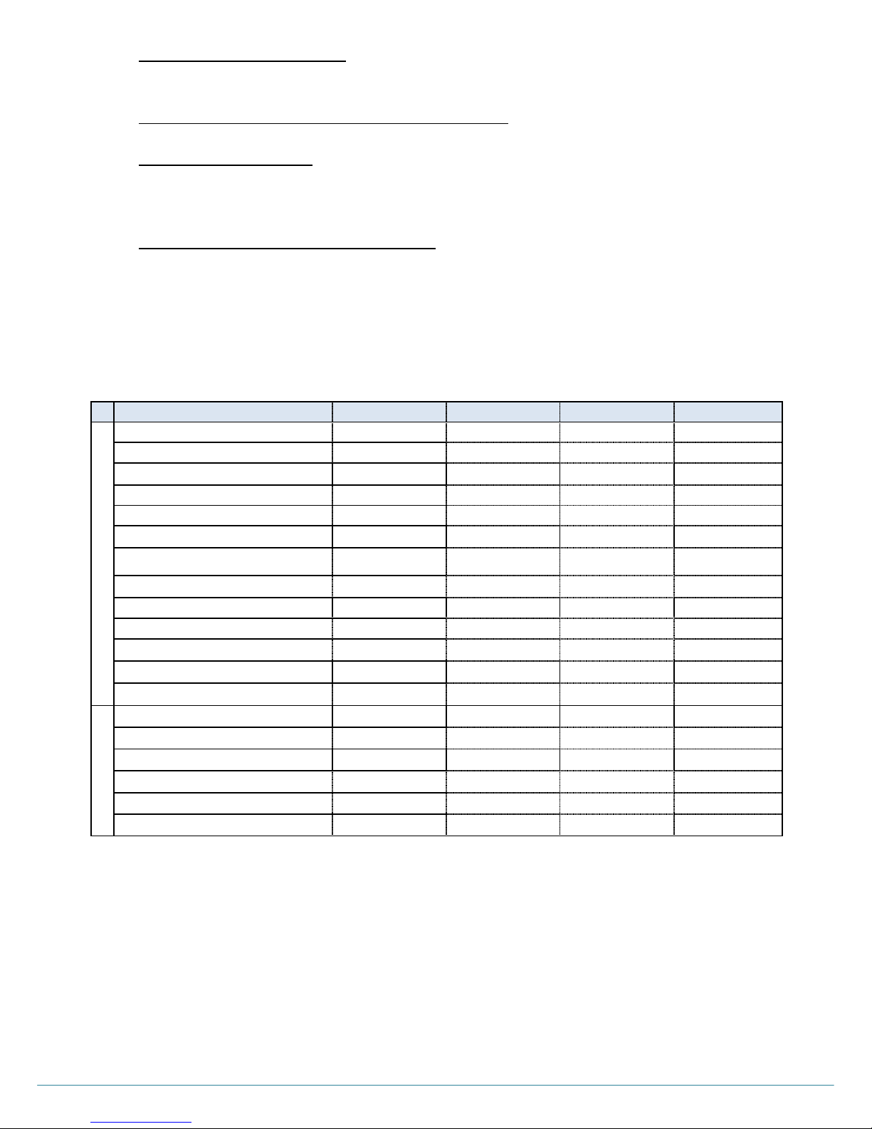
SYSTEMS AT A GLANCE
(BS:Base Station / MS:Mobile Station / BP:Belt Pack / RBS:Remote Station)
LT SERIES
LT750
LT550
LT250
LT150
SYSTEM
Frequency band
5GHz UNII
5GHz UNII
5GHz UNII
5GHz UNII
Station type
Fixed
Fixed
Fixed
Fixed or Mobile
Battery availability for Station
X X X
○
Number of full-duplex channel
11(1BS + 10BP)
11(1BS + 10BP)
9(1BS + 8BP)
5(1MS + 4BP)
Number of group channel
5 5 3
2
4-Wire port
○(1)
○(1) X X
Auxiliary I/O port
○(1)
○(1)
○(1)
○(1)
Number of RBS connection
10 5 1
X
BP connection and compatibility
BP750, MS150
BP550
BP250, BP550
BP150, BP750
Number of BP connection
128
128
128
128
Link, RSSI, Battery status Monitoring
○ (BS, BP)
○ (BS, BP)
○(BS, BP)
○(BP)
RF monitoring
○
○ (USB S/W)
X
X
BP # for group channel allocation
128
32
32
X
BELT PACK
Two groups communication (IC/ISO)
○ ○ ○
○
Side tone level adjustment
○ X X
○
Key lock
○ X X
○
Hands off sensibility level selection
○ ○ ○
○
Low cut adjustment
○(-3dB/-6dB)
X
X
○(-3dB/-6dB)
Maser BP function
○ X X
○
Page 8
ⓒ2016 LaON Technology Co., Ltd. All rights reserved. 7
SYSTEM USAGE EXAMPLE
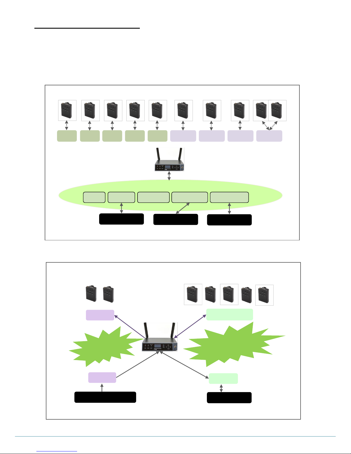
COMMUNICATION GROUP ALLOCATION
Single or multiple communication group channels up to five (5) can be allocated flexibly to the each device and the group
or groups can be selected for RX/TX.
Since the channels can be allocated to the 4-Wire and AUX Input/Output devices, the one (1) system supports various
communication ways such as IFB as well as IC and ISO.
On Belt Pack, communication in each group or simultaneous communications for two groups are available.
IFB and IC/ISO communications in ONE (1) system
Group 2 & 3
Group1: IFB
Group 2 : IC
Group 3 : ISO
Group 1
Auxiliary Microphone
4-Wire Device
Group 2
Group 1
BP1
BP2
BP10
BP17
BP28
BP127
BP128
… … …
Single or multiple or all groups can be allocated
BP1
BP2
Group 1
Group 2
Group 3
Group 4
Group 5
Group 1,2
Group 2,3
Group 3,4
Group 1,5
Group 1
Auxiliary Device
Group 2,3
Group 2,3,4
Group 1,2,3,4
Group 1,2,3,4,5
4-Wire Device
BS Headset
…
…
BP3
BP4
BP5
BP10
BP17
BP28
BP127
BP128
…
… … …
BS550 Base Station
Page 9
ⓒ2016 LaON Technology Co., Ltd. All rights reserved. 8
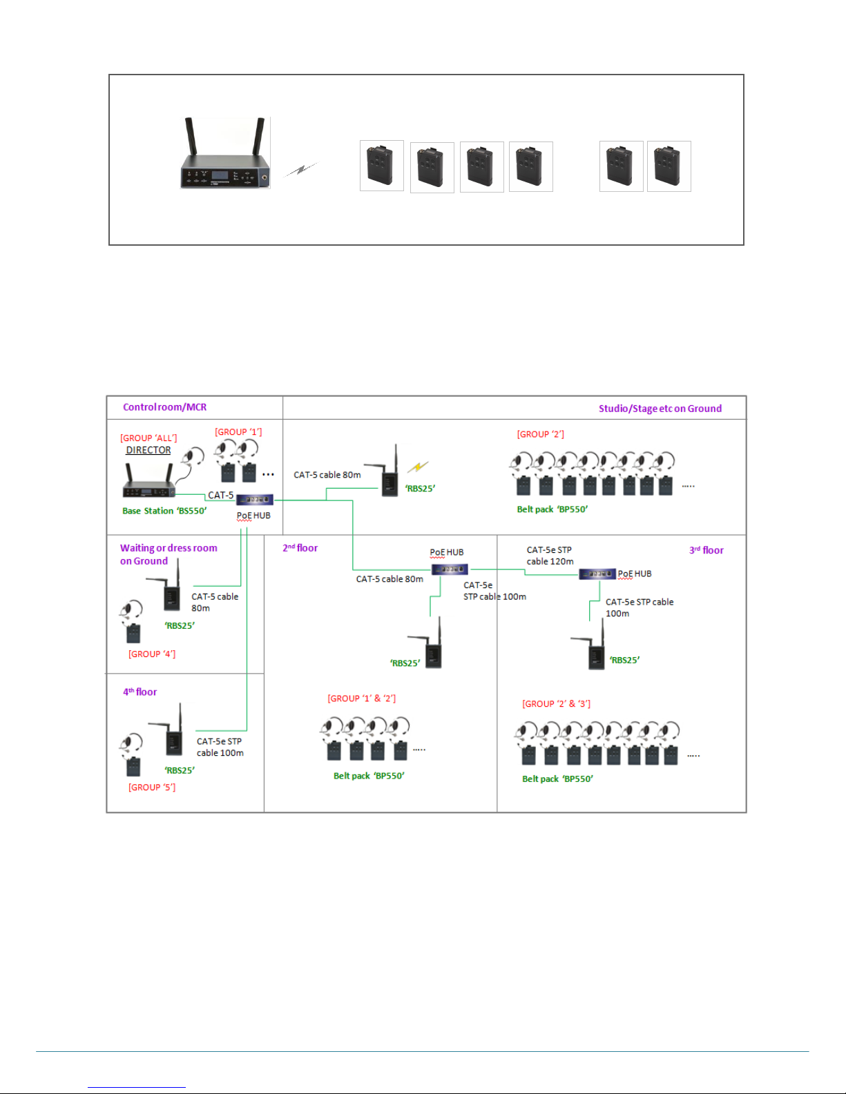
SYSTEM USAGE OF THE STAND-ALONE OPERATION
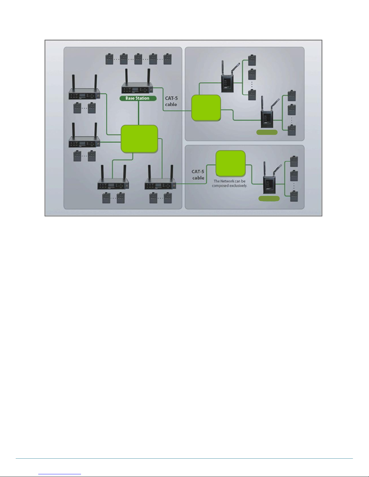
SYSTEM USAGE WITH THE REMOTE STATION
Up to five (5) Remote Station can be connected per Base Station, BS550. With the industry standard LAN network
configuration, multiple studio spaces or multi-floor sites can be easily consolidated.
This super-scalable Remote Station also provides extra-efficient functions such as PoE connection that does not require
a designated local power or battery, and automatic roaming between the Base Station and Remote Stations.
The system allows various types of network connection such as optical fiber cable, PoE and daisy-chain connection.
NOTE: It is highly recommended to compose the network exclusively due to the variable network environment.
……..
BP1
BP2
BP3
BP4
BP127
BP128
BS550 Base Station
BP550 Belt Pack
Page 10
ⓒ2016 LaON Technology Co., Ltd. All rights reserved. 9
SYSTEM USAGE WITH THE REMOTE STATION AND THE INTERCOM ROUTER
RBS25
Matrix
Intercom
Network
Switch
(LAN)
Network
Switch
(LAN)
RBS25
Page 11
ⓒ2016 LaON Technology Co., Ltd. All rights reserved. 10
SECTION 2: PRODUCT OVERVIEW
LT550 SYSTEM EQUIPMENTS
The followings are basic LT550 Wireless Intercom System equipments.
BS550 BASE STATION EQUIPMENTS
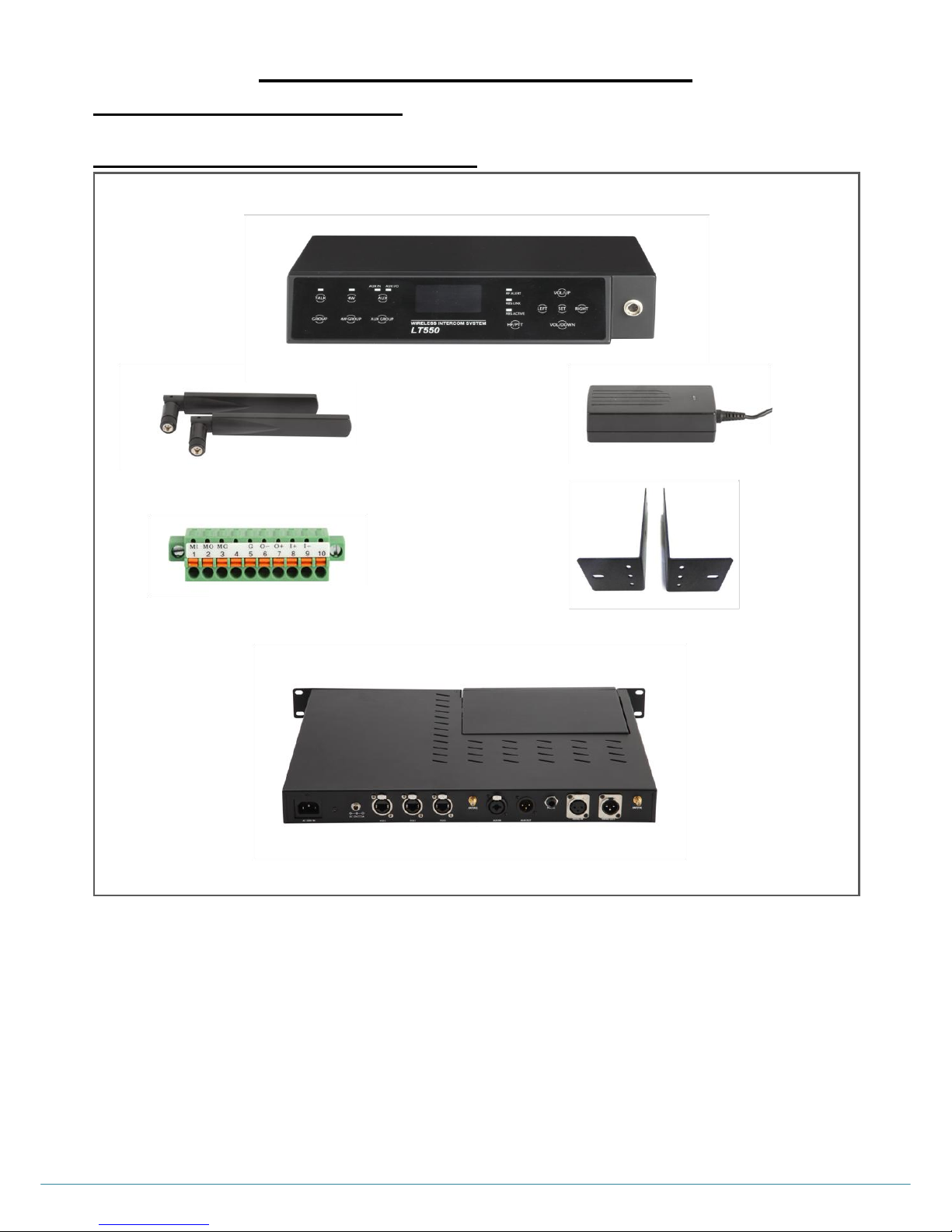
1RU RACK MOUNT KIT: This wing bracket accessory helps to install the Base Station on the 1RU rack. There are halls
on both side brackets to fix the antennas facing front.
1RU CASCADE KIT: The Base Station, BS550 can be docked to the 19” cascade kit. Locking power connector, 3 Pin
XLR connector for 4-Wire ports and AUX I/O ports, „Push-Pull Locking‟ type EtherCON connectors for three(3) PoE Ports
are provided on the rear panel of the cascade kit.
Base Station Antenna
BS550 Base Station
AC power adapter
1RU Cascade kit, BSCCK100 (Optional)
1RU Rack mount kit, BRK550 (Optional)
10 pin spring clamp connector
Page 12
ⓒ2016 LaON Technology Co., Ltd. All rights reserved. 11
BP550 BELT PACK EQUIPMENTS
BATTERY CHARGER AND HEDSET EQUIPMENTS
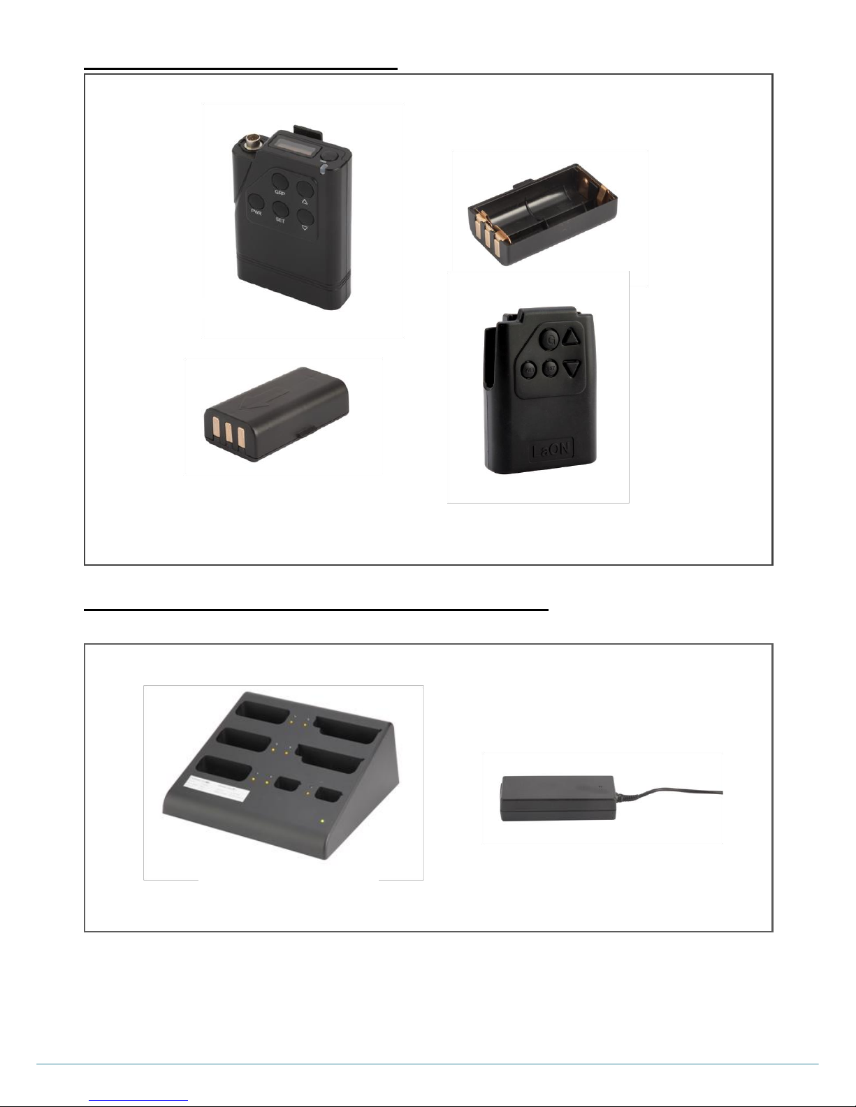
BATCHG125 BATTERY CHARGER EQUIPMENTS
AC Power Supply
BATCHG125 Battery Charger
BAT50 Rechargeable Battery Pack (Optional)
Battery sled
BP550 Belt Pack
BPPCH100 Belt Pack Pouch(optional)
Page 13
ⓒ2016 LaON Technology Co., Ltd. All rights reserved. 12
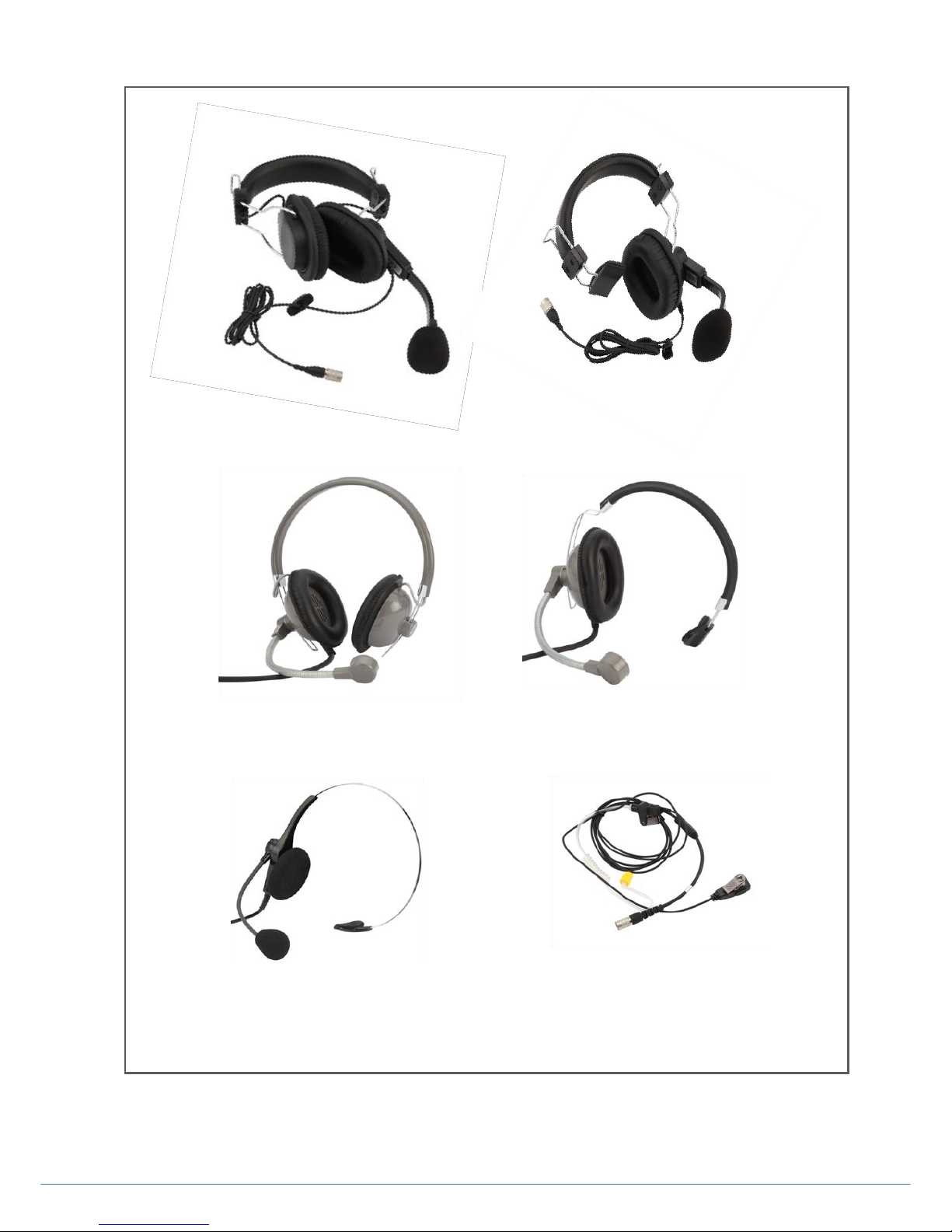
HEADSETS
NOTE: Headsets are designated to use for LAON's wireless intercom systems only.
LSH-S12 (Dynamic)
LMH-10 (Dynamic)
PTE-850 (Electret)
LMH-12 (Dynamic)
LSH-S125D (Dynamic)
LMH-125D (Dynamic)
Page 14
ⓒ2016 LaON Technology Co., Ltd. All rights reserved. 13
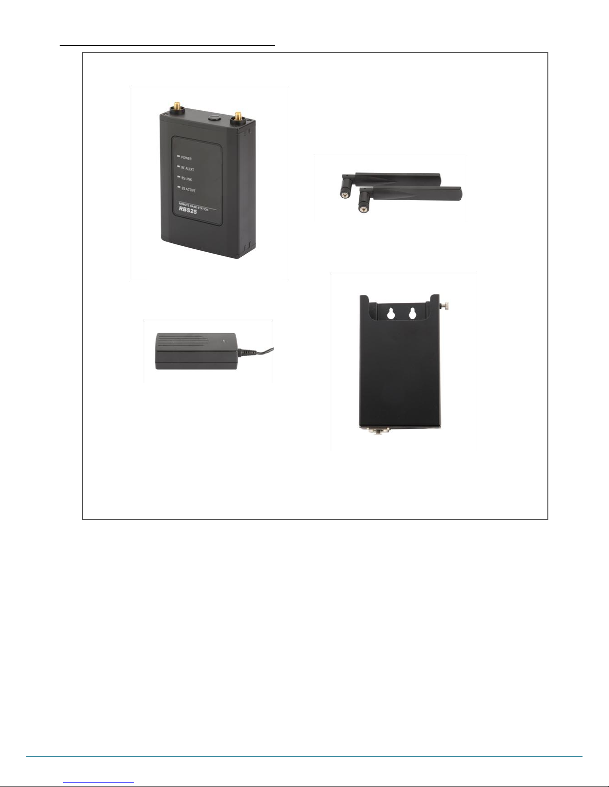
RBS25 REMOTE STATION EQUIPMENTS
Remote Station Holder: Insert a Remote Station and fix it with a screw on the holder. Connect the LAN cable by using
the „Push-Pull Locking‟ type EtherCON connector on the bottom of the holder. Install them on the wall or camera tripod or
microphone/light stand with interfacing screws.
AC Power Supply
RBS antennas
RBS25
Remote Station
RHD1000
Remote Station holder (Optional
Page 15
ⓒ2016 LaON Technology Co., Ltd. All rights reserved. 14
EQUIPMENTS OVERVIEW
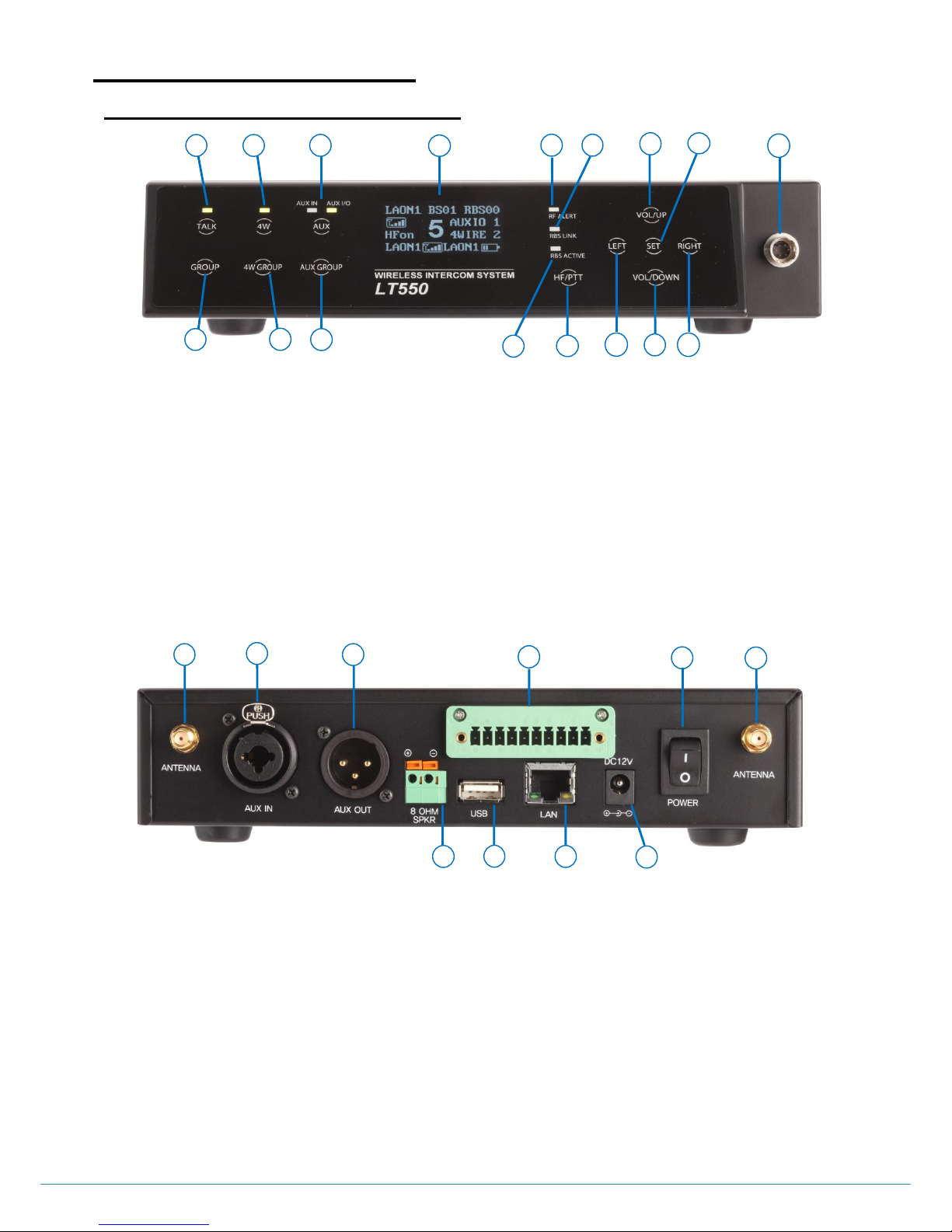
BS550 BASE STATION OVERVIEW
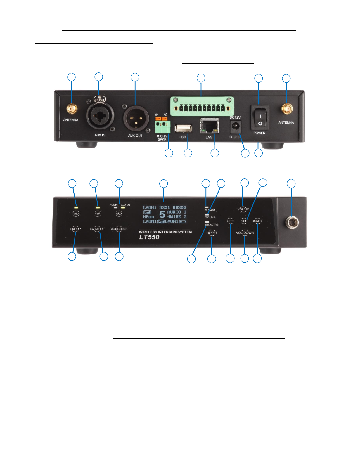
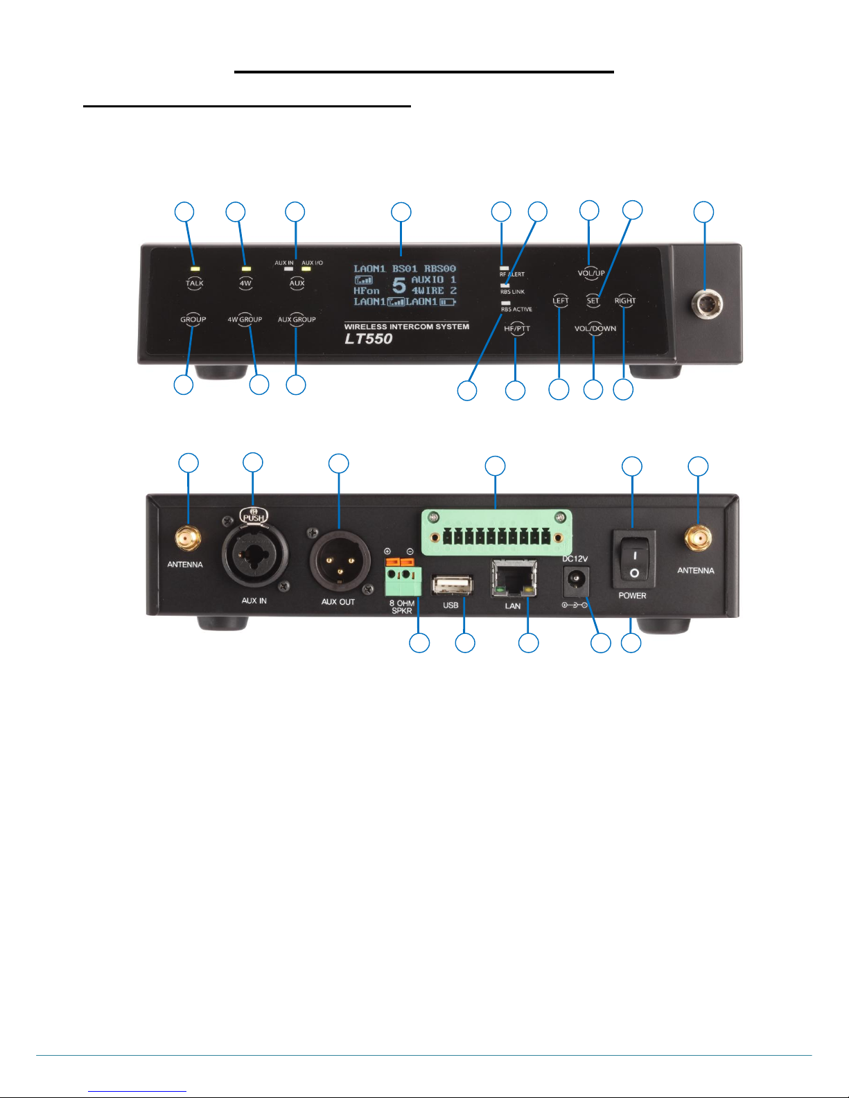
1. Headset TALK button with indicator light
10. Headset speaker volume control (UP)/Menu selection button
2. Headset communication group button
11. Headset speaker volume control (DOWN)/Menu Selection button
3. 4-Wire button with indicator light
12. Menu selection button (LEFT)
4. 4-Wire communication group button
13. Menu selection button (RIGHT)
5. AUX IN, AUX IN/OUT button with indicator light
14. Menu SET button
6. AUX IN, AUX IN/OUT communication group button
15. Headset cable connector (Receptacle)
7. RF ALERT indicator light
16. Hands Free/PTT mode selection button
8. Remote Station LINK Indicator light
17. OLED Display
9. Remote Station ACTIVE indicator light
1. Antenna connector
6. Antenna connector
2. AUX IN connector
7. 8-OHM speaker 2-pin spring clamp connector
3. AUX OUT connector
8. USB connector
4. 4-Wire connector
9. LAN RJ-45 connector
5. Power switch
10. POWER connector
1 2 3 4 5
6
7 8 9
10
Figure 2-2. Rear panel of the Base Station
17
14
15
16
12
1
3 5 2
4
6 7 8
10
9
11
13
Figure 2-1. Front panel of the Base Station
Page 16
ⓒ2016 LaON Technology Co., Ltd. All rights reserved. 15
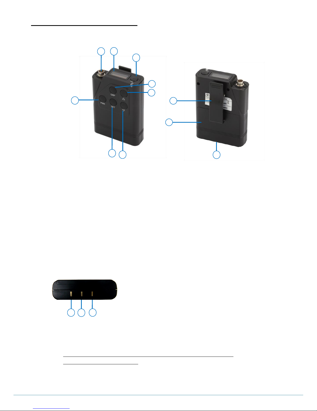
BP550 BELT PACK OVERVIEW
BP550 Belt Pack is moisture resistant which is excellent in using under humid environment.
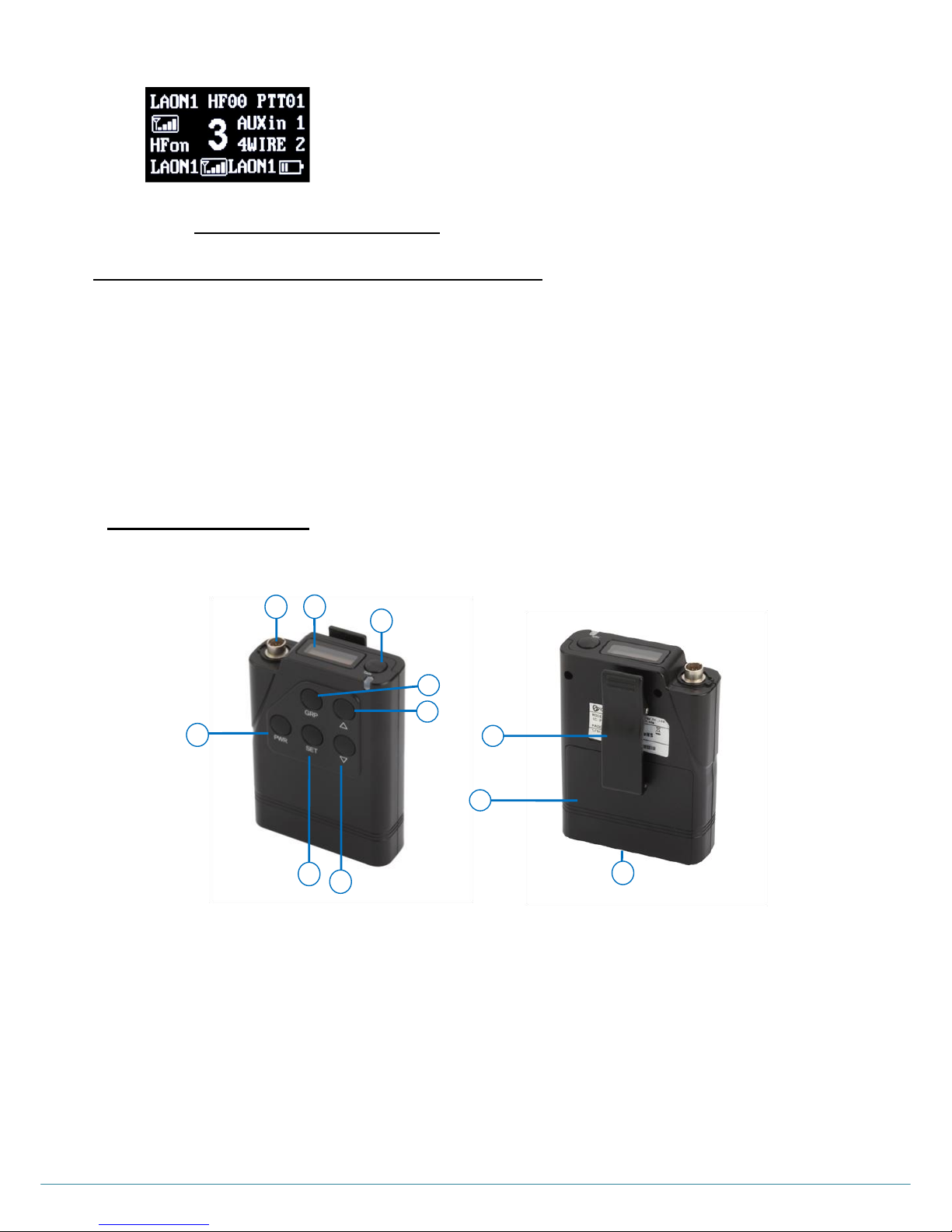
1. Headset cable connector (Receptacle)
7. Menu SET button
2. OLED display
8. Headset speaker volume control (DOWN) / Menu selection button
3. Headset TALK button with indicator light
9. Belt clipper
4. Power (PWR) button
10. Battery cover
5. Headset communication group (GRP) button
11. Charger terminals (Bottom of the Belt Pack)
6. Headset speaker volume control (UP) /
Menu selection button
Belt Pack pairing setup key: „PWR + SET‟
Manual hands off key: „PWR + PWR‟ (Double click of PWR)
BELT PACK CHARGER TERMINAL SPECIFICATION
NOTE
Do not stand the Belt Pack direct on electric conductors such as bracelets, keys and etc. and do not short the metal
contacts on the bottom of the Belt Pack with those electrically conducting material.
It is necessary to store the battery after fully charged and separating from the Belt Pack.
Turn off the Belt Pack before charging.
1
2
1. –
2. Temperature sensor
3. +
3
Figure 2-3. Panels of the Belt Pack
9
10
11
1 4 2
7
3
5
6
8
Page 17
ⓒ2016 LaON Technology Co., Ltd. All rights reserved. 16
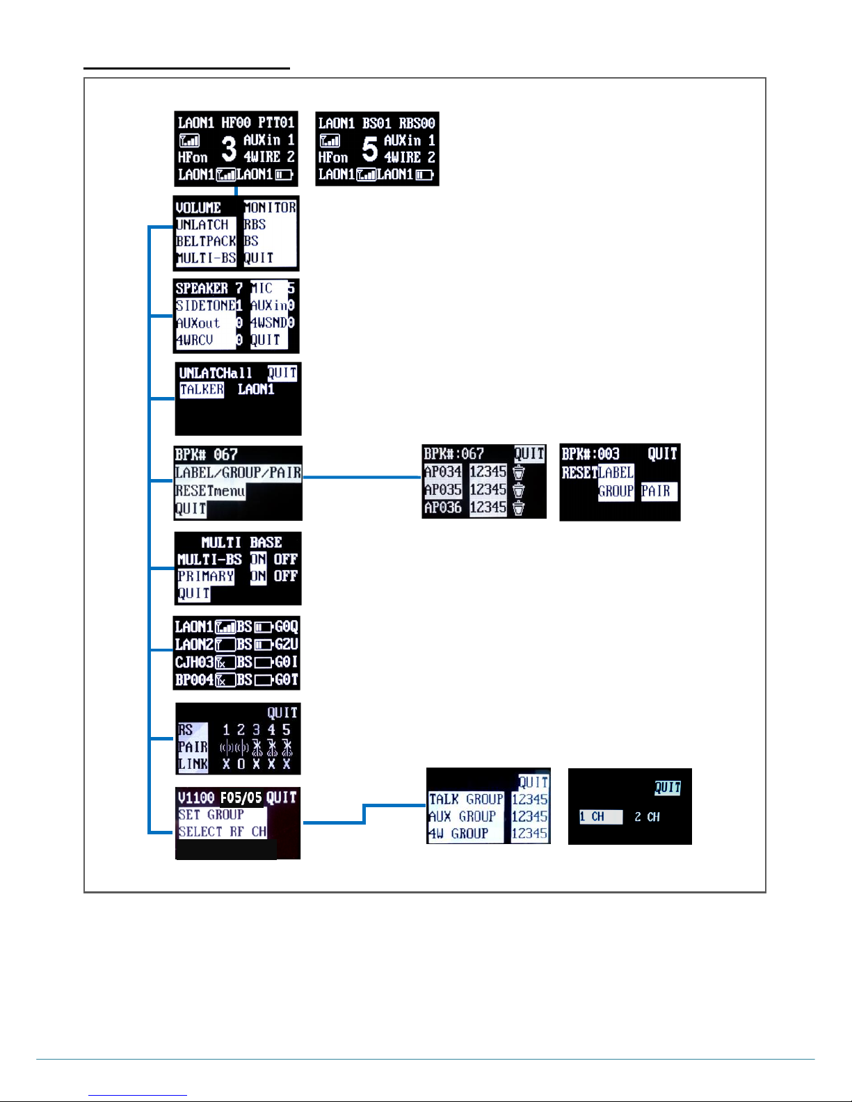
BASE STATION MENU
NOTE: Menu displays will be in sleep mode if no touch is made for approximately 30 minutes. Touching any button on the front
panel of the Base Station will have the screen waken up. Pressing SET button longer than 2 seconds on any menu screen will lead
you to NORMAL menu.
<MAIN menu>
<VOLUME menu>
<UNLATCH menu>
<RBS menu>
<BELTPACK menu>
<NORMAL menu>
<MULTI-BS menu>
<MONITOR menu>
<BS menu>
<LABEL/GROUP/PAIR menu>
<RESET menu>
<SET GROUP menu>
<SELECT RF CH menu>
Page 18
ⓒ2016 LaON Technology Co., Ltd. All rights reserved. 17
BELT PACK MENU
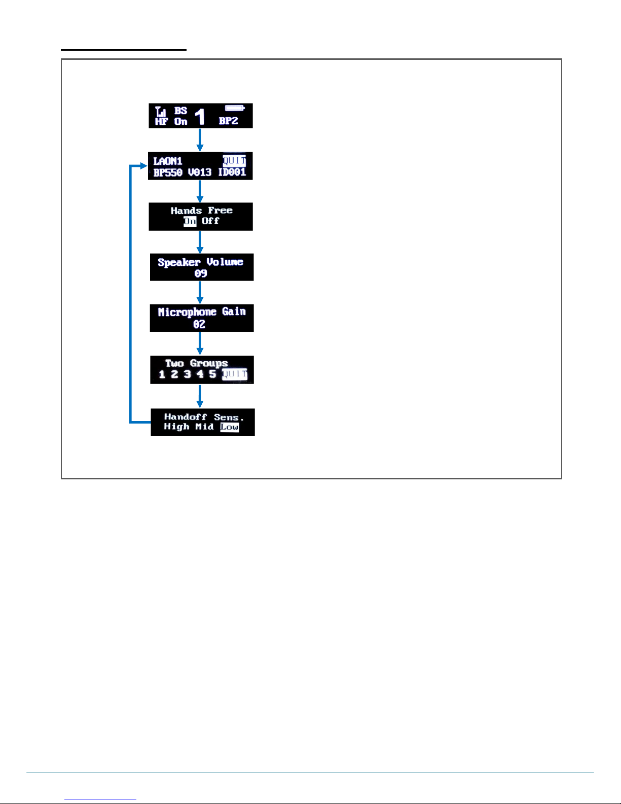
Pressing SET button on the NORMAL menu will lead you to MAIN menu.
On MAIN menu, press UP/DOWN direction key to move to the next menus.
Pressing PWR button on any menu screen will lead you to the NORMAL menu.
<MAIN menu >
<NORMAL menu >
<Hands Free On/Off selection menu>
<Speaker Volume adjustment menu>
<Microphone Gain adjustment menu>
<Two Groups setting menu>
<Handsoff Sensibility selection menu>
Page 19
ⓒ2016 LaON Technology Co., Ltd. All rights reserved. 18
SECTION 3: SYSTEM SETUP AND CONNECTIONS
BS550 BASE STATION SETUP
Following descriptions are stand-alone LT550 system configuration. Using additional devices such as Remote Stations, 4-wires,
auxiliary input/outputs and 8ohm speaker will be explained later on ADDITIONAL DEVICES SETUP in SECTION 5.
Step 1: Put two enclosed antennas to the antenna connectors (#1 and #6) on the rear panel of the Base Station. Turn the sleeve
on each of the antenna connectors clockwise to tighten them, and ensure that the antennas are connected firmly.
NOTE 1: These two antennas must be positioned vertically and be folded completely as 90 degree. Otherwise, it will be
caused to weaken the signal.
NOTE 2: While attaching the antennas directly to the rear panel of the Base Station, the Base Station should be away
from any metal obstructions, walls, and electronic equipments that can create radio interference. It is highly
recommended to place the antenna as high as possible in the center of the coverage and away from
obstructions.
Step 2: Plug the DC cable from the enclosed wall-adapter power supply into the 12VDC POWER connector (#10) on the rear of the
Base Station. Plug the large female connector at the end of the AC power cord into the power supply. Plug the other end of
the AC power cord into a standard wall outlet.
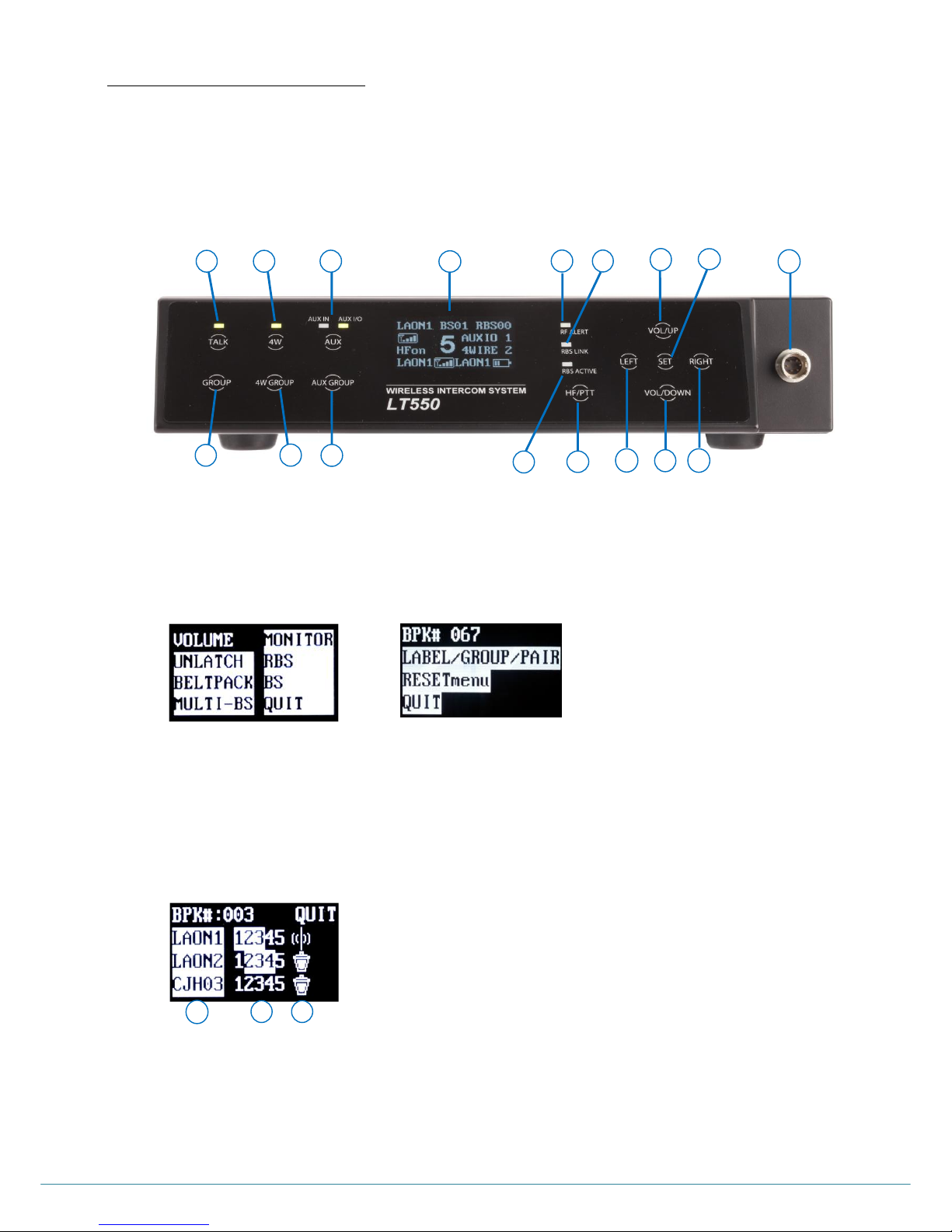
Step 3: The headset is with „Push-Pull Lock‟ type connector. Put a headset into the HEADSET connector (#15) on the front panel of
the Base Station. To disconnect the headset, hold the plug on the headset connector and pull out slightly turning.
Step 4: Press the POWER switch (#5) on the rear panel of the Base Station to turn on the Base Station. „DFS detecting‟ will be
indicated on the Base Station‟s front panel display and once the detecting is completed, NORMAL menu will pop up as
shown in Figure 3-3: The green light on top of the TALK button (#1), as shown in the Figure 3-2, should be flashing slowly
indicating the readiness of Base Station to start operations.
1
3
5
2
4
6
17
7
8
10
14
15
9
16
12
11
13
Figure 3-2. Front Panel of the Base Station
1
2
3 4 5 6 7 8 9
10
11
Figure 3-1. Rear Panel of the Base Station
Page 20
ⓒ2016 LaON Technology Co., Ltd. All rights reserved. 19
See the BS550 BASE STATION OPERATION in SECTION 4 for details about the NORMAL menu.
BP550 BELT PACK SETUP AND PAIRING UP
When you operate each Belt Pack for the first time with the Base Station, you must pair up the Belt Pack with a Base Station. This
pairing process allows a Base Station and a Belt Pack to recognize each other and an own cryptic code will be given for the
corresponding system. The Base Station will identify all the paired up Belt Packs and recognize the difference between the Belt
Packs. If a Belt Pack is added or replaced later, the new one is necessarily to be paired up with the Base Station. If the previous
Belt Pack will not be in use, turn off the Belt Pack or do the paring process again with a different label.
Each Base Station allows up to one hundred twenty eight (128) Belt Pack connections. The Base Station monitors various
information of the thirty two (32) Belt Packs, from the firstly paired up Belt Pack to thirty secondly paired up Belt Pack.
NOTE: BP550 can also be paired up with the Base Station, BS250. And BP550 will be connected to only one Base Station lastly
paired up with.
BELT PACK SETUP
Before pairing up the Belt Pack with the Base Station, set up all Belt Packs as following steps:
Slide the cover down to open the battery cover (#10), and put a fully charged rechargeable battery pack (BAT50) or battery sled
with two fresh AA 1.5V alkaline batteries. Make sure the position of polarity (+, -) is correct. Close the battery cover.
9
10
11
1 4 2
7
3
5
6
8
Figure 3-3. NORMAL menu
Page 21
ⓒ2016 LaON Technology Co., Ltd. All rights reserved. 20
PAIRING UP BELT PACKS
Check out the power status of the Base Station and each Belt Pack‟s, which will be paired up with. To execute a paring process,
the Base Station and Belt Packs should be turned on. Belt Packs should not go further than 3 feet (1 meter) from the Base
Station while they are being paired.
NOTE: Once paring is completed, the Base Station and each Belt Pack should go further than 6.5 feet (2 meters) to operate
otherwise, there could be audio breakups.
In NORMAL menu (#17) on the Base Station‟s front panel display, press SET (#14), then the MAIN menu appears, as shown
in Figure 3-5. Under MAIN menu, scroll (#10, #11, #12, #13) to and select „BELTPACK‟ and press SET (#14) then the
BELTPACK menu appears, as shown in Figure 3-6.
SETTING THE MAXIMUM NUMBER OF BELT PACKS (BPK#)
Enter the maximum number of Belt Packs that you want to pair up with the Base Station. Under the BELTPACK menu,
press SET(#14) on “BPK#” then input the maximum number by pressing UP, DOWN (#10, #11) buttons and press
SET(#14) to save. Move to next line „LABEL/GROUP/PAIR‟ and press SET(#14).
CREATING BELT PACK LABELS, COMMUNICATION GROUPS AND PAIRING
To set up the Labels and Communication Groups of Belt Packs, under the BELTPACK menu, move to and select
„LABEL/GROUP/PAIR‟. The LABEL/GROUP/PAIR menu appears, as shown in Figure 3-7. The maximum number of Belt
Packs set in BELTPACK menu will be displayed on the first row followed by BPK#. Belt Pack Labels will be shown as
„_P001‟ through „_P128‟ sequentially depending on the maximum number of Belt Packs set and you can customize the
Belt Pack Labels.
Figure 3-7. LABEL/GROUP/PAIR menu
A
B
C
A. Belt Pack Label
B. Communication Group
C. Pairing Icon
Figure 3-6. BELTPACK menu
Figure 3-5. MAIN menu
Figure 3-4. Front Panel of the Base Station
1 3 5
2
4
6
17
7
8
10
14
15
9
16
12
11
13
Page 22

ⓒ2016 LaON Technology Co., Ltd. All rights reserved. 21
NOTE: Up to 32 Belt Packs can be paired up with each Base Station in the normal mode. And, those 32 Belt Packs‟
Labels and Communication Groups can be edited and customized flexibly under the LABEL/GROUP/PAIR menu. The rest
of additional 96 Belt Packs under the shared mode are allocated to generic labels from “BP033” through “BP128” and into
the Communication Group “5” only automatically not being allowed for customization.
PARING ICONS
( ): Factory default status with no input of paring data
( ): Data edited and being ready to execute paring
( ): Paring processing
( ): Paring failed
( ): Paring completed - Base station can communicate with Belt pack from this stage.
CREATING OR CHANGING BELT PACK LABELS
To set Belt Pack Label, under the LABEL/GROUP/PAIR menu, move to Belt Pack Label section („A‟) by pressing LEFT
or RIGHT (#12, #13) and press SET on it to enter into the edit mode. Set the Label by pressing UP or DOWN (#10,
#11) then the display will show alphabets and numbers sequentially. After setting of the Belt Pack Labels, press SET
to save and move to Communication Group section („B‟). Then the icon ( ) will be changed to ( ).
When changing a Belt Pack Label for a Belt Pack which is already paired up, follow the same process. In this case, the
icon ( ) will be changed to ( ) once you enter into the edit mode.
ALLOCATING COMMUNICATION GROUPS TO BELT PACK
This process is to assign single or multiple group channels for the communication of each Belt Pack.
Move to a Communication Group number which you want to select by pressing LEFT or RIGHT. Single or multiple
groups within the five groups, „1 2 3 4 5‟ can be set for each Belt Pack by selecting the Communication Group number
and press SET on it to save one by one. To reverse the saved groups, press SET on the group number to be
reversed.
In order to change the Communication Group for a Belt Pack which is already paired up, follow the same process. In
this case, the icon ( ) will be changed to ( ) once you enter into the edit mode.
NOTE 1: Communication Group setting should be done correctly. Otherwise, it is not able to move out to the next step.
NOTE 2: Any Changes to be made in LABEL/GROUP/PAIR menu require paring process for the applicable Belt Packs
to reflect the changes. After modifying the Belt Pack Label and or Communication Group, implement the
pairing process again.
READY FOR PAIRING PROCESSING WITH BASE STATION
Once the Belt Pack Label and Communication Group set is done in the LABEL/GROUP/PAIR menu of the Base
Station and the applicable Belt Pack is ready, move on to the paring icon ( ) by pressing LEFT or RIGHT (#12, #13)
in the LABEL/GROUP/PAIR menu of the Base Station.
READY FOR PAIRING PROCESSING WITH BELT PACK
Turn on the Belt Pack by pressing PWR button for 2 seconds and confirm the NORMAL menu is displayed. When a
Belt Pack is not paired up yet, the LED adjacent to the TALK button will be blinking in red.
EXECUTING PARING PROCESSING WITH BASE STATION AND BELT PACK
Press SET on the paring icon ( ) in the menu display of the Base Station to execute paring processing. Then the
Base Station is in „paring processing mode‟ showing the icon ( ). At this time, for the Belt Pack, quickly press the SET
button on the front panel just after pressing and holding the PWR button. By doing this, the Belt Pack will also be in
„pairing processing mode‟ and the message, “Pairing…” will shortly appears on the Belt Pack display.
If the paring is completed successfully, the paring icon, ( ) will be shown in the Base Station display. And the Belt
Pack display will be shown as Figure 3-8 and shortly shows the NORMAL menu. If the paring is failed, the display will
be shown as Figure 3-9.
NOTE 1: When executing the paring processing with Belt Pack, after pressing and holding the PWR button, quickly
press the SET button and release the two buttons otherwise, the Belt Pack power may be off.
NOTE 2: While the pairing process, all communications will be halted temporarily and will be recovered upon
completing the pairing.
NOTE 3: When you pair up each Belt Pack with the Base Station for the first time, each ID number of the Belt Pack is
generated sequentially.
Page 23
ⓒ2016 LaON Technology Co., Ltd. All rights reserved. 22
IF PAIRING COMPLETED PROPERLY:
The display of the Belt Pack shows Belt Pack Label with an ID number that is sequentially generated from “1” to “128”.
If the paring is completed successfully “Paring…” message will be changed to “Paring Completed” within 20 seconds
as shown from Figure 3-8. And the LED adjacent to the TALK button of the Belt Pack is changed to green.
Move to QUIT and press SET button to back to the BELTPACK menu.
Repeat the paring processing for each Belt Pack.
IF PARING IS FAILED:
After the message “Pairing...” appears on the Belt Pack display, up to 20 seconds will be taken until the message,
“Pairing Failed” appears on the Belt Pack display. Try to process the paring again. If the paring is failed again, try
again after rebooting of the Belt Pack. If these processes do still not work, please contact your dealer or manufacturer
for the further supports.
PARING FOR REPLACEMENT
When you pair up a new Belt Pack („BP002‟) to replace one („BP001‟) that is already in paired mode, turn off the
„BP001‟ and execute the paring processing with the Belt Pack, „BP002‟. The „BP001‟ can be in use with another
alternative Belt Pack Label and ID after executing the paring up processing again.
NOTE: If a Belt Pack Label (ID) is duplicated, communication error may occur.
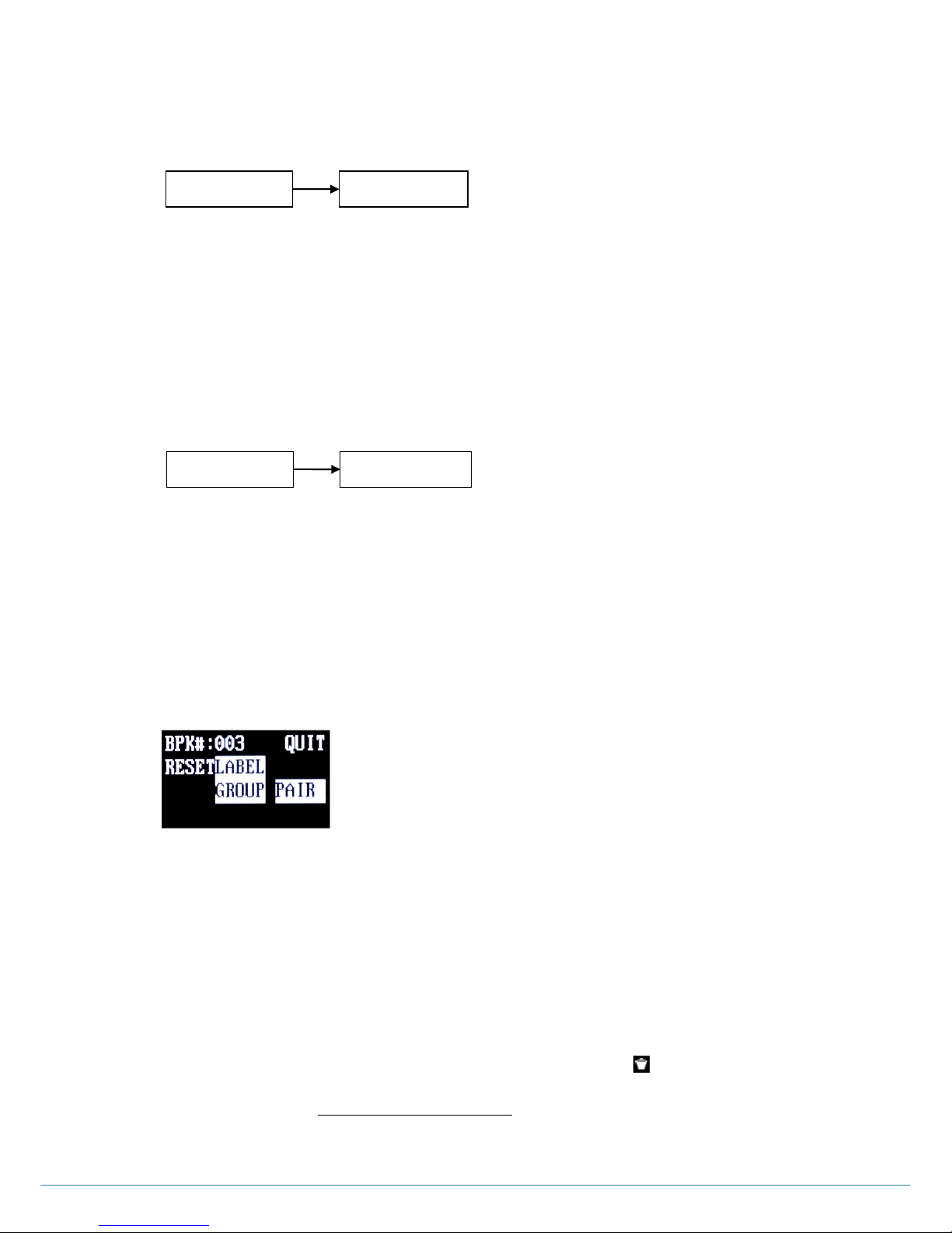
RESET BELT PACK LABELS, COMMUNICATION GROUP, PAIRING
In RESET menu under the BELTPACK menu, you can reset all the present pairing data of Belt Pack Labels and or
Communication Groups to the factory defaults. While processing resets on the Base Station and until the paring
processing is completed again, the communication with the applicable Belt Pack is not available.
RESET BELT PACK LABELS AND COMMUNICATION GROUP
Move to „LABEL‟ or „GROUP‟ and press SET button. The display shows “Yes No”, then move to “Yes” or “No” with
RIGHT or LEFT button and select. If you go to QUIT and press SET button, you can go back to BELTPACK menu.
Move to „LABEL‟ and select “Yes” then, all existing Belt Pack Labels will be overwritten to the factory defaults to „_P001‟
through „_P032‟. When you select „GROUP‟ and “Yes”, all the existing setups done earlier for Communication Groups
will be overwritten to the factory default and all the paring icons are changed to ( ).
NOTE: Re-pairing is necessary to use the Belt Packs after reset. Take an enough caution to reset all the data unless it
is really required. All data set earlier will be missing.
Figure 3-10. RESET menu
Pairing …
Pair- ID:000
Pairing Failed
Pairing …
BPK01 ID:001
Pairing Completed
Figure 3-8: Pairing completed status
Figure 3-9 : Pairing failed status
Page 24

ⓒ2016 LaON Technology Co., Ltd. All rights reserved. 23
RESET PARING
If you select “PAIR” in the RESET menu and “Yes”, existing Belt Packs‟ pairing data with the Base Station will be lost.
Under the BELTPACK menu, the maximum number of Belt Packs (BPK#), Belt Pack Labels and Communication
Groups are also changed to factory default. And original AES code given earlier of the Base Station will also be
changed then any Belt Packs paired up earlier are not able to communicate anymore with the Base Station. Therefore,
all the pairing setups for the Belt Packs should be done again.
BATCHG125 BATTERY CHARGER SETUP
The BATCHG125 is a seven-bay charger for charging the Belt packs, BAT50 and BAT150 Rechargeable Battery Pack. It is able to
charge up to five Belt Packs with the BAT50 Rechargeable Battery Packs are equipped, and two BAT50 Rechargeable Battery
Packs in about 4.5 - 5 hours. Using the Belt Pack/BAT150 dual bay, up to two BAT150 Rechargeable Battery Packs can be charged
instead of the Belt Pack. LEDs show charging status at all times.
See the “BATCHG125 Operating Instructions” for details.
Page 25
ⓒ2016 LaON Technology Co., Ltd. All rights reserved. 24
SECTION 4: SYSTEM OPERATION
BS550 BASE STATION OPERATION
Base Station is designed with soft-touch buttons to select menus, hand-free on/off, 4-wire, auxiliary input/output, communication
group, and so on. LEDs on the front panel indicate each selected modes and link status.
POWER ON/OFF
Power On
Turn on the POWER switch (#22) on the rear panel of the Base Station. NORMAL menu will be displayed after the
frequency scan process for a minute on the Base Station‟s front panel as shown from Figure 4-1 and 4-3: The green light
on top of the TALK button (#1) should be flashing slowly indicating the readiness of the Base Station to be in use.
Power Off
Turn off the POWER switch on the rear panel of the Base Station.
NOTE: When the green TALK light is on steady, the Base Station is transmitting audio data and when blinking, the Base
Station is receiving the audio but not transmitting the audio data.
18
19
20
21
22
23
24
25
26
27
28
Figure 4-1. Front Panel of the Base Station
1 3 5
2
4
6
17
7
8
10
14
15
9
16
12
11
13
Page 26
ⓒ2016 LaON Technology Co., Ltd. All rights reserved. 25
NORMAL MENU
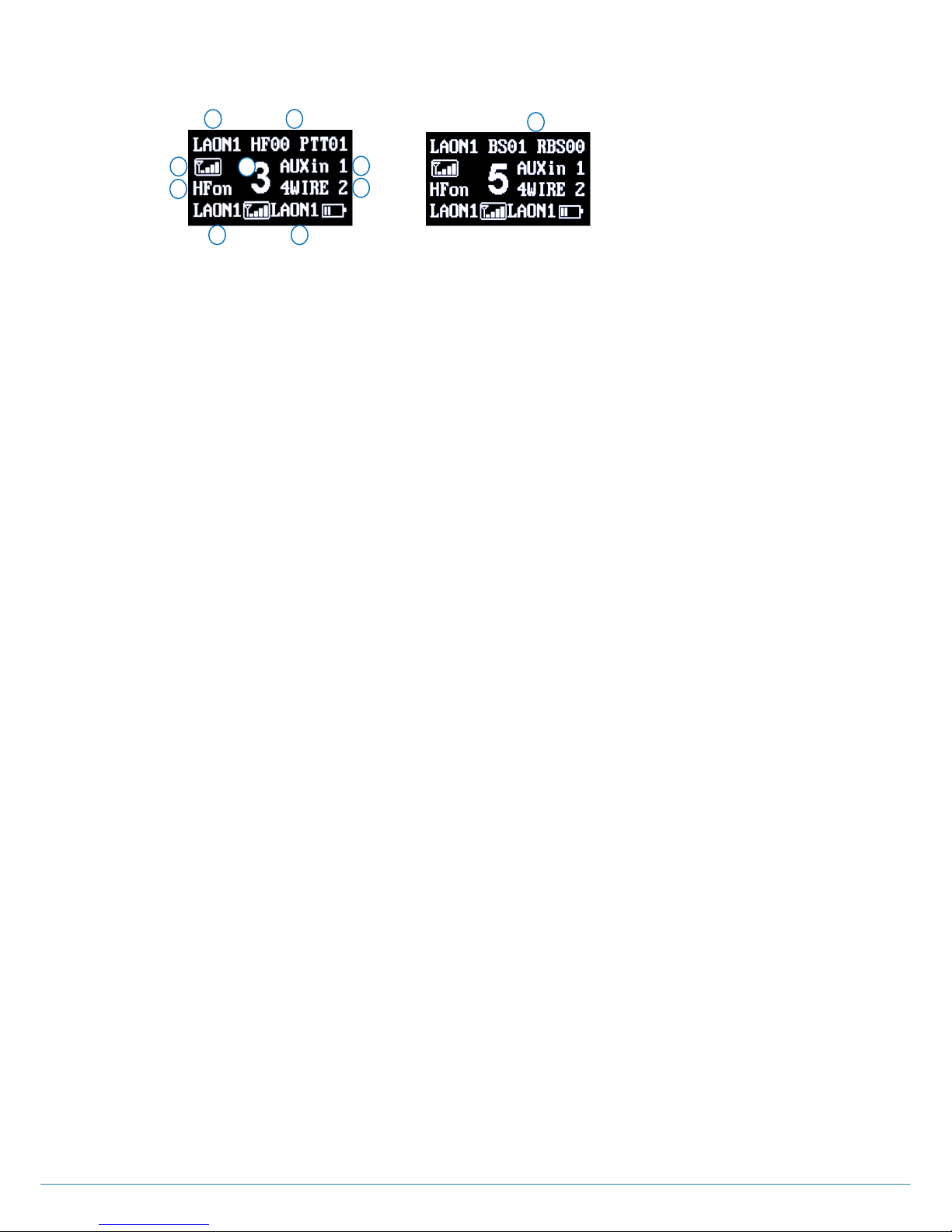
NORMAL menu will pop up when the Base Station is turned on. In order to move to the MAIN menu, press SET button.
When you press UP or DOWN button in the NORMAL menu, the headset speaker volume can be adjusted directly.
Followings are descriptions for NORMAL menu.
Item „A‟ indicates the Belt Pack Label that is most recently communicated within the selected group channel of the Base
Station.
Item „B‟ indicates Received Signal Strength Indication („RSSI‟) of the Belt Pack that is most recently communicated with
the Base Station. The RSSI level is presented graphically.
Item „C‟, the number next to “HF”, stands for the total number of Belt Packs that are transmitting the audio in Hands Free
on mode and the numbers next to “PTT” stand for the total number of Belt Packs that are transmitting the audio in Push-toTalk (Hands Free off) mode. The available number of Belt Packs that can transmit audio simultaneously is up to ten (10).
Item „D‟ will appear on the position of the item C alternatively, such as “BS07 RBS05”. The number next to “BS” stands for
the number of Belt Packs that are connected to the Base Station. The number next to “ RBS” stands for the number of Belt
Packs that is connected to the Remote Station. When the number of Belt Packs is in excess of 99, „FF‟ will be indicated to
instead.
Item „E‟, “HFon” appears on the display when the headset of the Base Station is in “Hands Free On” mode operation. Also,
when the headset of the Base Station is in “Push-to-Talk” (Hands Free off) mode operation, “HFoff” will appear on the
display.
Item „F‟ indicates the Communication Group of the Base Station. The number “1” through “5” stands for the
Communication Group that is selected by the Base Station operator. The character “A” stands that the Communication
Group is selected to “A” (All). The Base Station is able to do simultaneous communications with all the selected groups
that are set initially in the “TALK GROUP” menu of the Base Station.
Item „G‟ indicates the Communication Group of the auxiliary device. The display shows “AUXin” when AUX IN is enabled,
and shows “AUXIO” when AUX IN and AUX OUT are enabled both. The number “1” through “5” next to “AUXin” or “AUXIO”
stands for the Communication Group of the auxiliary device that is selected by the Base Station operator. The character “A”
stands that the Communication Group is selected to “A” (All). The Base Station is able to do simultaneous communications
with all the selected groups that are set initially in the “AUX GROUP” menu of the Base Station. The Communication
Group will be shown on NORMAL menu as following examples.
AUXIn 2: Auxiliary Input is enabled and the Communication Group of auxiliary device is set to “2”.
AUXIO 1: Auxiliary Input and Output are enabled both and the Communication Group of auxiliary device is set to “1”.
AUXIO A: Auxiliary Input and Output are enabled both and the Communication Group of auxiliary device is set to “A”
(All).
AUX X: Auxiliary devices are not enabled.
Item „H‟ indicates the Communication Group of the 4-wire. The display shows the status of the 4-wire enabled or disabled
status and the corresponding 4-wire Communication Group. The number “1” through “5” next to “4WIRE” stands for the
Communication Group of the 4-wire device that is selected by the Base Station operator. The character “A” stands for that
the Communication Group is selected to “A” (All). The Base Station is able to do simultaneous communications with all the
selected groups that are set initially in “4W GROUP” menu of the Base Station. The Communication Group will be shown
on NORMAL menu as following examples.
4WIRE 1: 4-wire is enabled and the Communication Group of 4-wire is set to “1”
4WIRE A: 4-wire is enabled and the Communication Group of 4-wire is set to “A” (All).
4WIRE X: 4-wire devices are not enabled.
Item „I‟ indicates the Belt Pack Label that is in the lowest Received Signal Strength Indication (RSSI) level. The RSSI level
is presented graphically.
Item „J‟ indicates the Belt Pack Label that is in the lowest battery Level. The battery level is presented graphically.
NOTE: Initially, when there has been no Belt Pack paired up, the Belt Pack Label indications of „A‟, „I‟ and „J‟ in the
NORMAL menu will be displayed as „_P000‟ and the corresponding graphic level indications will be empty.
Figure 4-3: NORMAL Menu
Page 27

ⓒ2016 LaON Technology Co., Ltd. All rights reserved. 26
TALK AND COMMUNICATION GROUP BUTTONS
Communication Group Button (#2)
Communication Groups of the Base Station is set as “1” (Group 1) by the factory default. Press the Base Station‟s
Communication Group (#2) button on the front panel of the Base Station and select Communication Group. The
Communication Group will be changed from “1” to “5”, and to “A” (All) by each pressing. The Communication Group “1” will
come again after “A” (All). Every time you press and release the Communication Group button, a voice message “Group o
ne to five or all” will be heard from the headset. Selected Communication Group is displayed on the NORMAL menu of the
Base Station, as following examples.
1: Base Station‟s Communication Group is selected to “1”:
A: Base Station‟s Communication Group is selected to “A” (All).
If you select the Communication Group of Base Station same as that of 4W or AUX IO, the headset of the Base Station
should be able to hear audio from the 4W or AUX IO, and the 4-wire or the auxiliary device should be able to hear audio
from the headset of the Base Station.
TALK Button (#1)
Push-To-Talk (hand-free off) Mode Setting
For push-to-talk (PTT) communication, press HF/PTT button. PTT mode is on when “HF off” appears on the screen. A
voice message “Hands free off” will be heard in the headset. Press TALK button while talking.
NOTE: After setting the PTT mode, hands-free on mode is disabled until it is changed to hands-free-on mode.
PTT Mode Operation
Press and hold the TALK button for talking. In PTT operation, audio will be transmitted only while you are pressing the
TALK button.
Hands-Free-On Mode Setting
For hands-free-on (HFon) communication, press HF/PTT button. Hands-Free-On mode is on when “HF on” appears on the
screen. A voice message “Hands free on” will be heard in the headset. In hands-free-on mode, the Base Station‟s headset
can be operated in either hands-free-on or PTT operation.
Hands-Free-On Mode Operation
Press and release the TALK button to latch the transmission then the greed LED will be on. After latch the transmission,
talk and listen work as in normal telephone conversation. Press and release the TALK button again to stop the
transmission, and you can listen only.
TALK light
When the Base Station is transmitting, the light on top of the TALK button should be on steady. When the Base Station is
ready but not transmitting, that is listen only status, the light on top of the TALK button will be blinking slowly.
AUX AND AUX COMMUNICATION GROUP BUTTONS
AUX Button (#5)
With AUX button you can select three options - auxiliary Input (AUX IN) only or auxiliary Input and Output (AUX I/O) or no
use of auxiliary device. Each mode is set by pressing AUX button sequentially. When auxiliary input is selected, AUX IN
light on top of the AUX button will be on. When you use the auxiliary input and the auxiliary output devices at the same
time, select AUX I/O. When AUX I/O is selected, AUX I/O light on top of the AUX button will be on. When both are not
activated, the lights of AUX IN and AUX I/O on top of the AUX button will be off.
AUX Communication Group Button (#6)
Communication Group of the auxiliary device is set to use “1” (Group 1) by the factory default. Press AUX GROUP (#6)
button on the front panel of the Base Station, and select Communication Group for the auxiliary device. The
Communication Group will be changed from “1” to “5”, and to “A” (All) by each pressing. The Communication Group “1” will
come again after “A” (All). Selected AUX Communication Group is displayed on the NORMAL menu of the Base Station,
as shown in Figure 4-3:
4W AND 4W COMMUNICATION GROUP BUTTONS
4W Button (#3)
Page 28
ⓒ2016 LaON Technology Co., Ltd. All rights reserved. 27
4W button allows for enabling or disenabling the connection of the 4-wire device. Two modes will be toggled by pressing
4W button. The light on top of the 4W button will be on or off depending on the selection status.
4-WIRE Communication Group Button (#4)
Communication Group of the 4-wire device is set as “1” (Group 1) by the factory default. Press the 4W GROUP (#4) button
on the front panel of the Base Station, and select the Communication Group for the 4-wire device. The Communication
Group will be changed from “1” to “5”, and to “A” (All) by each pressing. The Communication Group “1” will come again
after “A” (All).
Selected 4-wire Communication Group is displayed on the NORMAL menu of the Base Station, as shown in Figure 4-3.
STAUS LIGHTS ON THE BASE STATION‟S FRONT PANEL
RF ALERT light (#7)
When there are audio breakups seriously, RF ALERT light will go on.
RBS LINK light (#8)
When the Remote Station is connected, RBS LINK light will go on.
RBS ACTIVE (#9)
When the Remote Station exchanges data with the Base Station, RBS ACTIVE light will be flashing.
MENU CONTROL
MAIN Menu
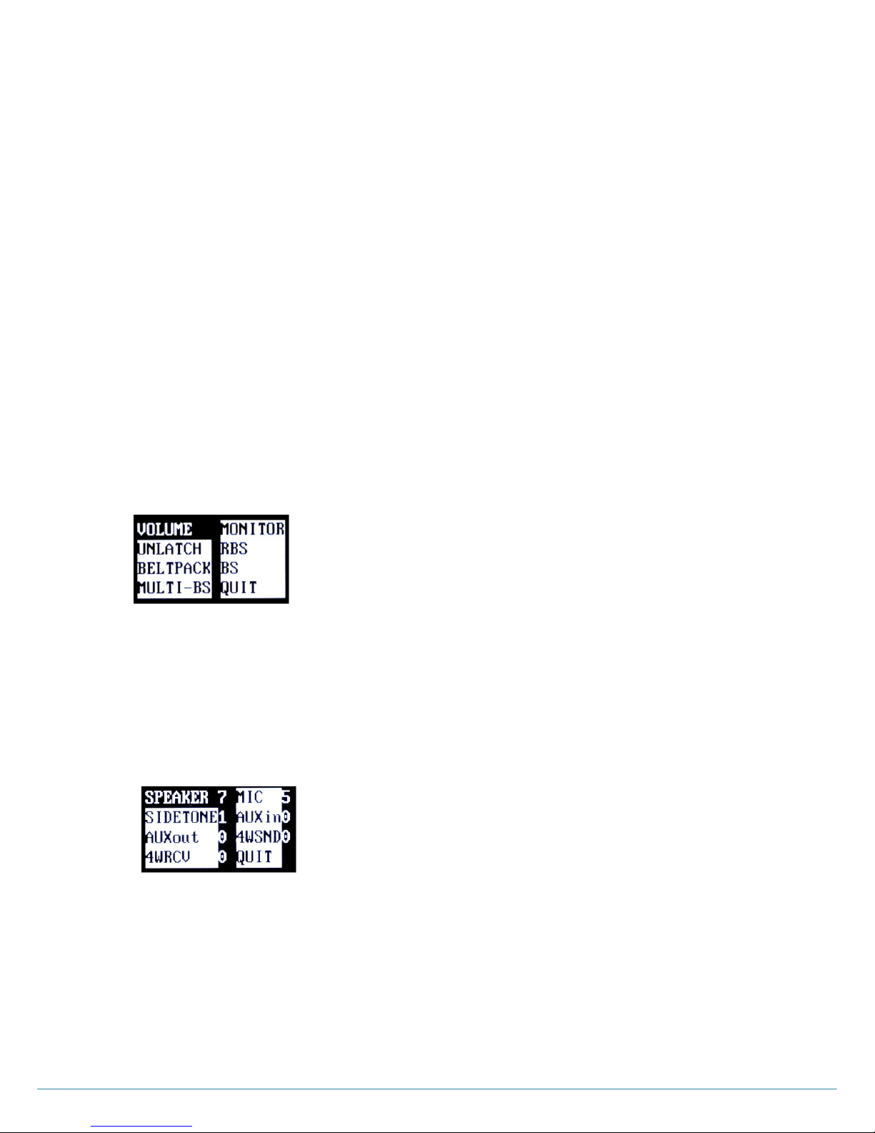
Press SET under the NORMAL menu, and the MAIN menu appears, as shown in Figure 4-4: Move to and press SET to
select on each menu, VOLUME, MONITOR, UNLATCH, BS, RBS and BELTPACK. Move to and press SET to select QUIT
or press SET for 2 seconds on any item to return to the NORMAL menu.
VOLUME Menu
Move to and press SET on VOLUME, to get into the VOLUME menu as shown in Figure 4-5. You can adjust volumes of the
Base Station‟s headset and external speaker by selecting SPEAKER. And you can adjust the microphone gain by selecting
MIC, the side tone by selecting SIDETONE of the Base Station‟s headset, auxiliary Input and output level by selecting
AUXin and AUXout and 4-wire sending and receiving level by selecting 4WRCV and4WSND. Move to and select QUIT or
press SET for 2 seconds on any item to return to the MAIN menu.
Headset Volume Up and Down
Move to SPEAKER, press SET to select and adjust headset speaker volume with UP or DOWN. And also pressing UP or
DOWN button under the NORMAL menu, enables you to adjust the volume directly.
Volume Up
Every time you press and release the volume up button, a beep sound will be heard from the headset. When the level
is reached out to a maximum, a voice prompt, “maximum” will be heard from the headset.
Figure 4-5. VOLUME menu
Figure 4-4. MAIN menu
Page 29

ⓒ2016 LaON Technology Co., Ltd. All rights reserved. 28
Volume Down
Every time you press and release of the volume down button, a beep sound will be heard from the headset. When the
level is reached out to a minimum, a voice prompt, “minimum” will be heard from the headset.
NOTE: Either a headset speaker or an external speaker can be used. The SPEAKER volume is for adjusting volume
levels of both.
Headset Side tone Up and Down
You can adjust headset side tone volume by selecting SIDETONE under the VOLUME menu. Use UP or DOWN to adjust
headset side tone volume.
Volume Up
Every time you press and release the volume up button, a beep will be heard from the headset. When the level is
reached out to a maximum, a voice prompt, “maximum” will be heard from the headset.
Volume Down
Every time you press and release of the volume down button, a beep will be heard from the headset. When the level is
reached out to a minimum, a voice prompt, “minimum” will be heard from the headset.
Headset Microphone Gain Up/Down
To adjust the headset microphone gain, move to and press SET to select MIC under the VOLUME menu, and then press
UP or DOWN.
Microphone Gain Up
Every time you press and release the volume up button, the increased voice level will be heard from the headset while
you are speaking to headset microphone. When the level is reached out to a maximum, a voice prompt, “maximum”
will be heard from the headset.
Microphone Gain Down
Every time you press and release the volume up button, the decreased voice will be heard from the headset while you
are speaking to headset microphone. When the level is reached out to a minimum, a voice prompt, “minimum” will be
heard from the headset.
Auxiliary Input and Output Volume Up/Down
You can adjust auxiliary input and output level by selecting AUXin and AUXout each under the VOLUME menu. Use UP
or DOWN to adjust the auxiliary input and output level.
Input or Output Volume Up
Every time you press and release the volume up button, a beep sound will be heard from the headset. When the level
is reached out to a maximum, a voice prompt, “maximum” will be heard from the headset.
Input or Output Volume Down
Every time you press and release the volume down button, a beep sound will be heard from the headset. When the
level is reached out to a minimum, a voice prompt, “minimum” will be heard from the headset.
4-Wire Sending and Receiving Volume Up/Down
You can adjust 4-wire sending and receiving level by selecting 4WSND and 4WRCV each under the VOLUME menu.
Use UP or DOWN to adjust the 4-wire sending and receiving level.
Sending or Receiving Volume Up
Every time you press and release the volume up button, a beep sound will be heard from the headset. When the
level is reached out to a maximum, a voice prompt, “maximum” will be heard from the headset.
Sending or Receiving Volume Down
Every time you press and release the volume down button, a beep sound will be heard from the headset. When the
level is reached out to a minimum, a voice prompt, “minimum” will be heard from the headset.
NOTE: HEADSET SAFETY
Please note that there could possibly be various root causes of distortion, echo or cut-off of the microphone
sounds of the headset. At the initial set up, for the safe use, it is encouraged to set these volume levels lower and
start to adjust for the best level required by various site environments and improve matters caused by the relevant
headset where applicable.
When the microphone gain, side tone or speaker volume on a specific headset is set too high, it is possibly cause
a kind of echo or distortion. Try to these gain or volume down for improving and mitigate the relevant matter.
Page 30
ⓒ2016 LaON Technology Co., Ltd. All rights reserved. 29
MONITOR Menu
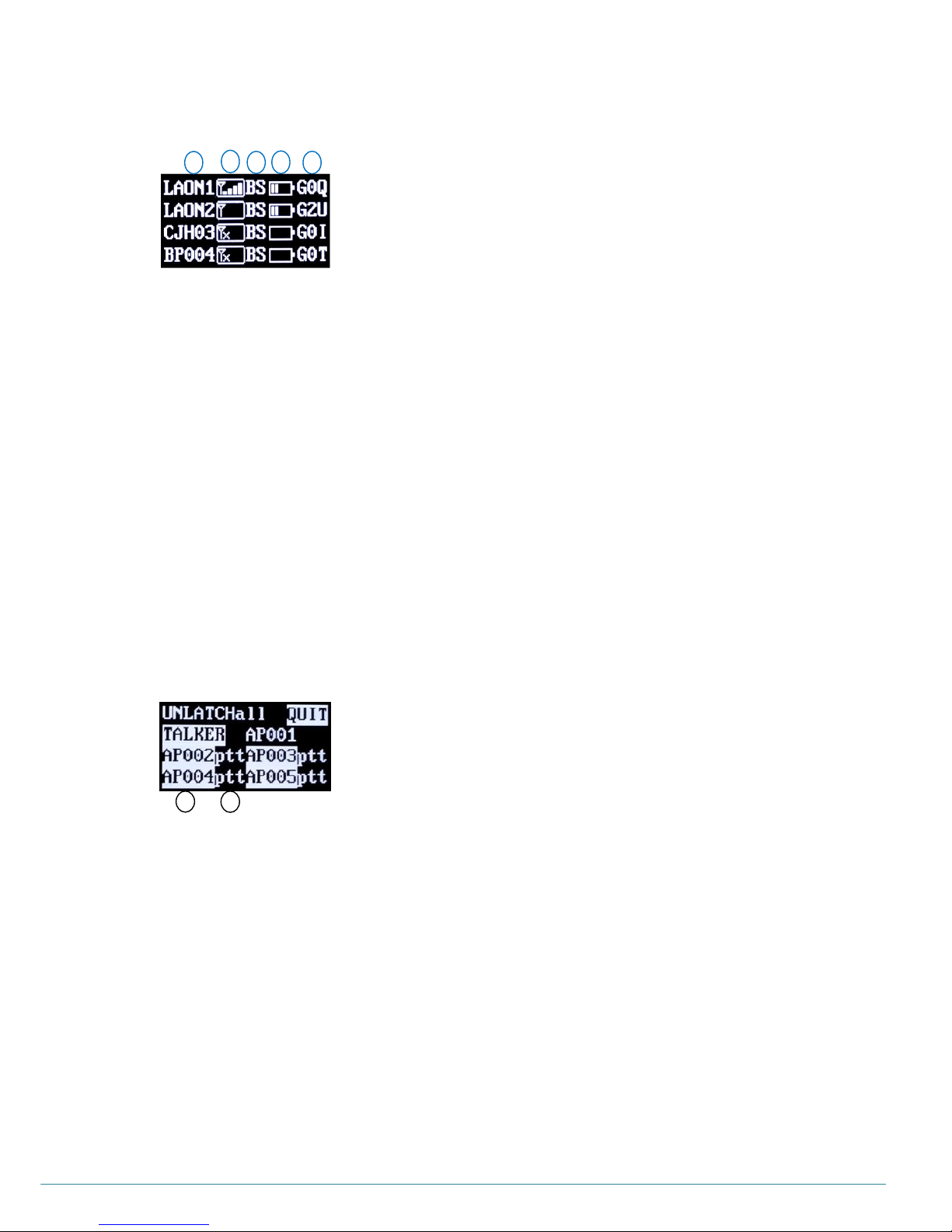
Move to and press SET to select MONITOR then, MONITOR menu appears as shown in Figure 4-6:
The MONITOR menu shows that each Belt Pack is connected to which Remote Station or Base Station. Also you can
monitor each Belt Pack‟s RSSI, battery and microphone gain levels at the same time. From the monitor screen, users
can monitor up to thirty secondly paired up Belt Packs.
The item „A‟ indicates the Label of each Belt Pack. The item „B‟ indicates the Received Signal Strength Indication (RSSI)
level of each Belt Pack. The RSSI level is presented graphically. The item „C‟ indicates the applicable Belt Pack is
connected to which Remote Station or Base Station. If the Belt Pack is connected to the Base Station, “BS” will appear. If
the Belt Pack is connected to the Remote Station, a Remote Station‟s ID number “R1” through “R5” will appear. When
the Belt Pack is not connected to any of the Remote Station or Base Station, the display shows a message “NC”. The
item „D‟ indicates the battery level of each Belt Pack. The battery level is presented graphically. The item „E‟ indicates the
headset microphone gain of each Belt Pack. The number next to „G‟ stands for the level of the microphone gain from „1‟
to „5‟.
You can scroll with UP or DOWN button, and move with LEFT or RIGHT button. Move to and press SET to select QUIT,
or press SET for 2 seconds to return to the MAIN menu.
UNLATCH Menu
Move to and press SET to select UNLATCH then the UNLATCH menu appears as shown in Figure 4-7.
When you need to unlatch the transmissions of a Belt Pack, use this UNLATCH menu. The Base Station operator may
want to stop the transmission of specific Belt Packs that are used in hands-free-on mode or Push-to-Talk mode.
Each Base Station can have up to eleven (11) full-duplex audio paths - 10 channels for Belt Pack and 1 channel for Base
Station. The display shows up to ten (10) Belt Pack Labels that are transmitting to the Base Station or the Remote
Station. Under the UNLATCH menu, move to and select „UNLATCH all‟, then, all transmissions of the Belt Pack are
unlatched. If all transmissions of the Belt Pack are unlatched successfully, the display shows only “QUIT” and
“UNLATCH Completed” message on the second row. When you press SET to select TALKER, a current or most recently
talked Belt Pack will be unlatched. If a transmission of the current or most recently talked Belt Pack is unlatched
successfully, the text of “TALKER” and its Belt Pack Label will disappear from the UNLATCH menu. The item „A‟ column
is for the Belt Pack Labels. The item „B‟ indicates the status of the Belt Pack that is in hands-Free-On or push-to-talk
mode operation. The “hf” stands for the Belt Pack in hands-free-on mode operation. The “ptt” stands for the Belt Pack in
push-to-talk mode operation. Move to and press SET to select each Belt Pack Label, then a transmission of the selected
Belt Pack is unlatched. If a transmission of the selected Belt Pack is unlatched successfully, selected Belt Pack Label
and its status will disappear from the UNLATCH menu.
You can scroll with UP or DOWN, and move with LEFT or RIGHT button. Move to and select QUIT or press SET for 2
seconds to return to the MAIN menu.
Figure 4-7. UNLATCH menu
A
B
Figure 4-6. MONITOR menu
D
E
C
B
A
47
48
Page 31

ⓒ2016 LaON Technology Co., Ltd. All rights reserved. 30
BELTPACK, RBS and BS Menu
See the “BP550 BELT PACK SETUP AND PAIRING UP” in SECTION 3 and “ADDITIONAL DEVICES SETUP” in
SECTION 5.
VOICE MESSAGE IN THE HEADSET OF THE BASE STATION
“Beep”
“Maximum”
“Minimum
“Group one”
“Group two”,
“Group three”
“Group four”
“Group five”
“Group all”
Page 32
ⓒ2016 LaON Technology Co., Ltd. All rights reserved. 31
BP550 BELT PACK OPERATION
POWER ON/OFF
Power On
Press the power button (#4, „PWR‟) longer than three (3) seconds to turn on the Belt Pack. A voice message “Power on” will
be heard from the headset, and the red TALK light adjacent to the TALK button will go on. After a few seconds, TALK light
will be changed to green slow flashing, indicating the Belt Pack is ready to use, if the pairing with the Base Station is
properly done.
Power Off
Press and hold the PWR button for approximately two seconds. A voice message “Power off” will be heard in the headset
and then the green slow flashing TALK light will go off.
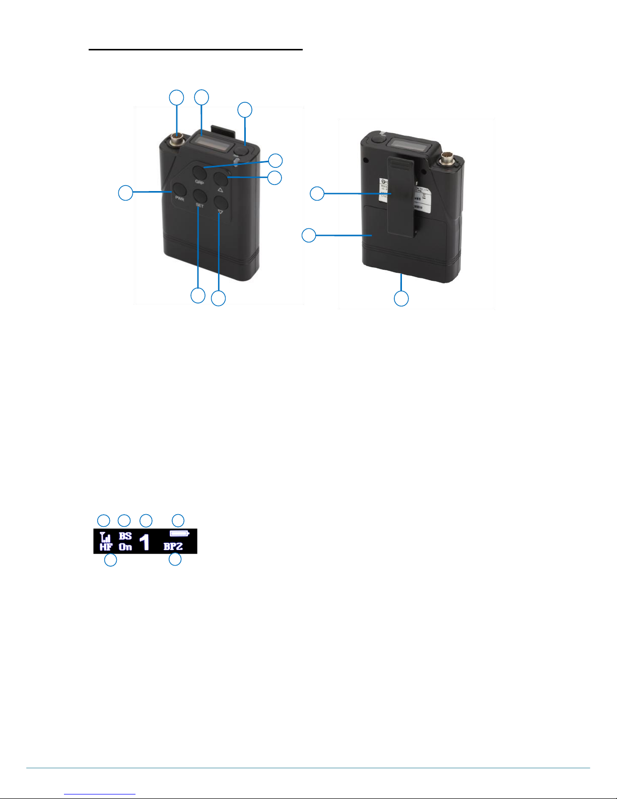
NORMAL MENU ON THE BELT PACK‟S UPPER PANEL DISPLAY
The item „A‟ indicates the Belt Pack‟s Received Signal Strength Indication (RSSI) level. The RSSI level is presented
graphically.
The item „B‟ indicates that the applicable Belt Pack is connected to which Remote Station or Base Station. When the Belt
Pack is connected to the Base Station, “BS” will be shown. When the Belt Pack is connected to the Remote Station, the
combination of “R” and “ID number of the Remote Station” will be shown. The „ID number‟ is assigned to each Remote
Station upon pairing up with the Base Station.
The item „C‟ indicates the Communication Group of the Belt Pack‟s headset. The numbers “1” through “5” stand for the
number of the Communication Groups.
The item „D‟ indicates the Belt Pack‟s battery level. The battery level is presented graphically.
The item „E‟ indicates the Belt Pack‟s label.
The item „F‟ indicates Belt Pack‟s operation mode. If the headset of Belt Pack is in the hands-free-on mode operation, “HF
on” appears on the display. If the headset of Belt Pack is in the push-to-talk (Hands Free off) mode operation, “HF off”
appears on the display.
Figure 4-8. NORMAL menu
9
10
11
1 4 2
7
3
5
6
8
Page 33

ⓒ2016 LaON Technology Co., Ltd. All rights reserved. 32
TALK AND BELTPACK COMMUNICATION GROUP BUTTONS
Belt Pack Communication Group Button (#5)
Up to five (5) communication groups, single or multiple, can be allocated and configured flexibly to Belt Pack by the Base
Station operator using the „LABEL/GROUP/PAIR‟ menu under the „BELTPACK‟ menu of the Base Station. For example, a
Belt Pack may belong to only one communication group of the group # 1, two communication groups of the group # 1 & 2,
three communication groups of the group # 2, 3 & 5, four communication groups of the group # 1, 3, 4 & 5, and five
communication groups of the group # 1, 2, 3, 4 & 5.
Belt Packs in the same communication group can talk with others in the designated group. Communication Groups of the
Belt Pack is initially set to “1” (Group 1) by the factory default. To select Communication Group on the Belt Pack, press the
Communication Group button (#5) on the front panel of the Belt Pack. It will be changed sequentially by each pressing, from
“1” to “5” within the allocated Communication Groups by the Base Station operator. Every time you press the Communication
Group button, a voice message will be heard from the headset. The selected Communication Group is displayed on the
NORMAL menu of the Belt Pack, as following examples.
“1” : Belt Pack‟s Communication Group is selected to “1”:
“5” : Belt Pack‟s Communication Group is selected to “5”.
If you select a Belt Pack‟s Communication Group same as that of 4-wire or auxiliary input/output, the headset of the Belt Pack
should be able to listen the 4-wire or auxiliary device groups, and the 4-wire or auxiliary device should be able to listen the
Belt Pack.
TALK Button (#3)
Push-To-Talk (hand-free off) Mode Setting and Operation
You can set a Belt Pack to be in Push-To-Talk (PTT) communication mode in the “Hands Free” menu. A voice message
“Hands free off” will be heard from the headset.
NOTE: After selecting the PTT mode, hands-free-on mode is disabled until it is changed to hands-free-on mode.
Press and hold the TALK button while talking. In PTT operation, audio will be transmitted only while you are pressing the
TALK button.
Hands-Free-On Mode Setting and Operation
You can set a Belt Pack to be in hands-free-on (“HFon”) communication mode in the “Hands Free” Menu. A voice message
“Hands free on” will be heard from the headset.
In order to transmit, press and release the TALK button to latch the transmission. After latching the transmission, talk and
listen work as in normal telephone conversation. Press and release the TALK button again to stop the transmission, and you
can listen only.
TALK Light
When the Belt Pack is transmitting, the light on top of the TALK button will be on steady. When the Belt Pack is ready but
not transmitting, that is listen only status, the light on top of the TALK button will be flashing slowly. When the Belt Pack is
not ready for transmitting the audio, the light on top of the TALK button will be flashing red rapidly.
TALK Light Operation
Green on steady: Listen and talk mode
Green flashing slowly: Listen only mode
Red flashing quickly: The Belt Pack is not paired up yet or is not linked to any Base Station or Remote Station
(out of coverage)
Red on steady: When the battery level is low, a voice message, “Change the battery” will be heard from the
headset and the green LED will be changed to red.
HOW TO CONTROL MENUS
MAIN Menu
Press any button of the front panel if the screen is in sleep mode, then the „NORMAL‟ menu appears.
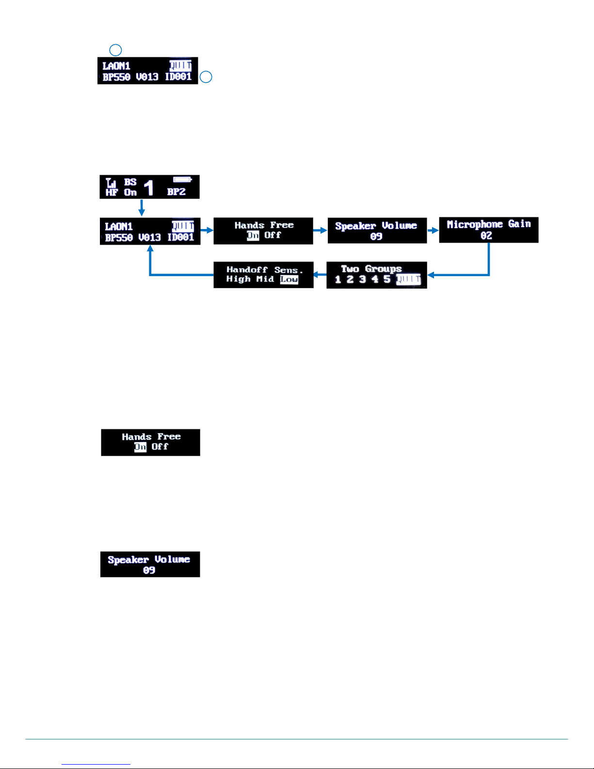
Press SET button under the NORMAL menu, then he MAIN menu appears as shown in Figure 4-9.
Page 34
ⓒ2016 LaON Technology Co., Ltd. All rights reserved. 33
The item „A‟ indicates the Belt Pack‟s Label.
The item „B‟ indicates the Belt Pack‟s model name, software version and ID number.
On the MAIN menu, press SET to back to NORMAL menu.
Under the MAIN menu with UP or DOWN button, move to each one of HANDS FREE, SPEAKER VOLUME,
MICROPHONE GAIN, TWO GROUPS and HANDSOFF SENSIBILITY menus sequentially and select a menu by
pressing SET button. The selected menu will be flashing and ready to be edited. Use UP or DOWN button to change
values. Press SET to save the settings and move to next field. Pressing once the power button will lead you to NORMAL
menu directly.
HANDS FREE Menu
Move to HANDS FREE menu, and press SET button to select a mode with UP or DOWN button. If a Belt Pack is in
shared mode, there is no option to select Hands Free On mode and it only operates in “Off” mode.
SPEAKER Volume Menu
Move to SPEAKER VOLUME menu, press SET button to select and adjust headset speaker volume level with UP or
DOWN button. And press UP or DOWN button in the NORMAL menu will also allow you to change the speaker volume
level directly.
Speaker Volume Up
Every time you press the volume up button, a beep sound will be heard from the headset. When the level is reached out
to a maximum, a voice prompt, “maximum” will be heard from the headset.
Speaker Volume Down
Every time you press the volume down button, a beep sound will be heard from the headset. When the level is reached
out to a minimum, a voice prompt, “minimum” will be heard from the headset.
Figure 4-12. SPEAKER VOLUME menu
Figure 4-11. HANDS FREE menu
Figure 4-10. Menus shown sequentially
MAIN menu
NORMAL menu
Figure 4-9. MAIN menu
Page 35
ⓒ2016 LaON Technology Co., Ltd. All rights reserved. 34
NOTE: HEADSET SAFETY
Please note that there could possibly be various root causes of distortion, echo or cut-off of the microphone
sounds of the headset. At the initial set up, for the safe use, it is encouraged to set these volume levels lower and
start to adjust for the best level required by various site environments and improve matters caused by the relevant
headset where applicable.
When the microphone gain, side tone or speaker volume on a specific headset is set too high, it is possibly cause
a kind of echo or distortion. Try to these gain or volume down for improving and mitigate the relevant matter.
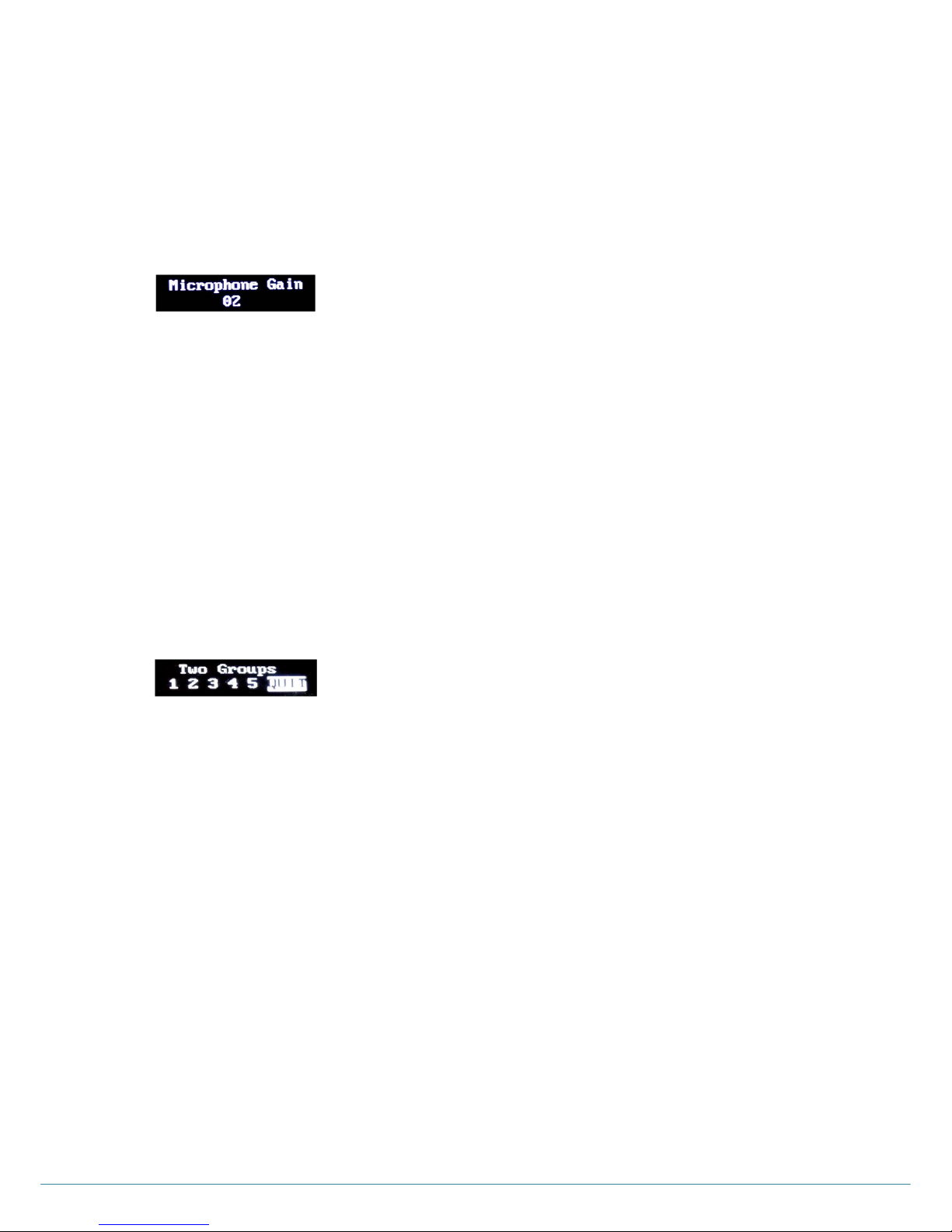
MICROPHONE GAIN Menu
Move to MICROPHONE GAIN menu, press SET button to select and adjust headset microphone gain level with UP or
DOWN button.
Microphone Gain Up
Every time you press the volume up button, increased voice level will be heard from the headset while you are speaking
to headset microphone. When the level is reached out to a maximum, a voice message, “maximum” will be heard from
the headset.
Microphone Gain Down
Every time you press the volume down button, decreased voice level will be heard from the headset while you are
speaking to headset microphone. When the level is reached out to a minimum, a voice message, “minimum” will be
heard from the headset.
TWO GROUPS Menu
TWO GROUPS menu is to set a „simultaneous listen mode‟ for selected two groups within the allocated group channels
to the Belt Pack. Once the TWO GROUPS mode is set, the Belt Pack user can only select the two groups with the
communication group selection button (#5, „GRP‟) on the front panel of the Belt Pack. And, only one selected group with
the communication group selection button (#5, „GRP‟) is allowed for „Listen & Talk mode‟ within the two groups.
Move to the TWO GROUPS menu and press SET to enter into the edit mode. Move to the desired communication group
number to select by pressing UP or DOWN button and press SET on the number. Then the communication group
number will be reversed and set. On the screen of the TWO GROUPS menu, initially allocated communication group
numbers to the Belt Pack will only be displayed. And, setting two (2) groups is necessary for the „two groups listen‟ mode.
Otherwise, the set value will not be saved. To reset the groups, reverse all the set values and reset. Move to QUIT on the
menu with UP or DOWN button and press SET to save. To release the „two groups listen‟ mode, reverse all the set
values in the menu.
NOTE: TWO GROUPS menu will not appear if there is initially only one group channel is allocated for the Belt Pack.
Figure 4-15. TWO GROUPS menu
Figure 4-13. MICROPHONE GAIN menu
Page 36

ⓒ2016 LaON Technology Co., Ltd. All rights reserved. 35
HANDSOFF SENSIBILITY Menu
HANDS OFF SENSIBILITY menu is to set hands off sensibility level. In case there are wide overlapping areas due to site
or installation environment between the Base Station and Remote Station or Remote Stations, set the sensibility to ‟High‟
or „Mid‟ and check out the most appropriate level. With the level, „High‟, the hands off will be done the fastest.
NOTE: If no action is taken for 10 seconds on any menu, all changes made will be saved automatically except any setup in
TWO GROUPS menu and the display will be off.
CHANGE BATTERIES
When Battery level became weak, a voice message, “Change battery” will be heard in the headset. When this happens,
open the battery cover by sliding down, and remove batteries from the Belt Pack. The removable battery sled will hold two
1.5v alkaline batteries. When you use two alkaline batteries, insert two 1.5v alkaline batteries into the battery sled, and put it
in the battery holder on the rear of the Belt Pack. When replacing a battery, make sure the position of polarity (+, -) is correct.
VOICE MESSAGE IN THE HEADSET OF THE BELT PACT
“Power on”
“Power off”
“Hands free on”
“hands free off”
“Beep”
“Maximum”
“Minimum”
“Audio channel is busy”
“Unlatched”
“Change battery”
“Out of coverage ”
“Group one”
“Group two”
“Group three”
“Group four”
“Group five”
Figure 4-16. HANDS OFF SENSIBILITY menu
Page 37
ⓒ2016 LaON Technology Co., Ltd. All rights reserved. 36
SECTION 5: ADDITIONAL DEVICES SETUP
The following instructions are regarding for connections and setups additional devices such as 4-wire intercoms, auxiliary audio
devices, external 8 ohm speakers and Remote Stations.
Additional Devices and Communication Group Set Up
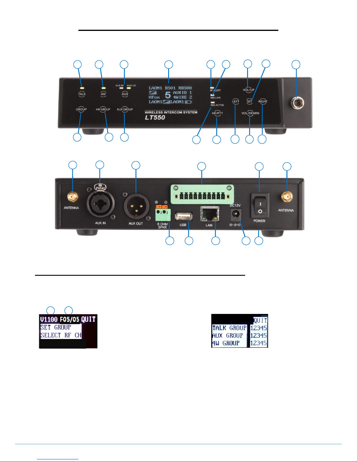
In order to set Communication Group channels for external devices and the Base Station, select „SET GROUP‟ in the BS menu.
The display shows the Software version information of the Base Station and the ID of a frequency band currently being used at the
Base Station will be shown on the first row as shown from Figure 5-3.
On SET GROUP menu, move to each row with direction buttons to set single or multiple Communication Group channels to the
additional devices and the Bas Station. TALK GROUP is to set for a headset of the Base Station. Once the Communication Groups
are assigned for AUX and 4-Wire device, the Base Station and Belt Packs can communicate with the external devices by selecting
the same group channel.
For a headset of the Base Station, select “TALK GROUP”, for Auxiliary device, select “AUX GROUP”; and for 4-Wire, select “4W
GROUP”. In each row, use LEFT or RIGHT to move to desired Communication Group number from „1‟ to „5. Single or multiple
groups within the five groups, „1 2 3 4 5‟ can be set for each device by moving onto the Communication Group numbers and
pressing SET to save one by one. Once the Communication Group channels are set initially in this menu, operator can select a
group number to communicate within the range from the front panel of the Base Station. Move to and select QUIT to return to MAIN
Menu.
Figure 5-4. SET GROUP Menu
Figure 5-3. BS Menu
A
B
A. Software version of the Base Station
B. ID of frequency band being taken
Figure 5-2. Rear Panel of the Base Station
16
17
18
19
20
21
22
23
24
25
26
1
3 5 2 4 6
17
7
8
10
14
15
9
16
12
11
13
Page 38
ⓒ2016 LaON Technology Co., Ltd. All rights reserved. 37
4-WIRE INTERCOM SETUP
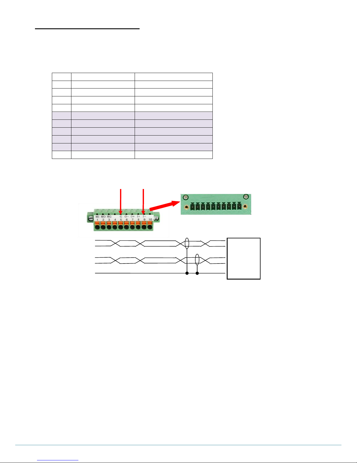
Step 1: When you use with a 4-wire intercom device, plug the enclosed 10 pin spring clamp connector into the „ 4-WIRE connector‟
(#21) on the rear panel of the Base Station, as shown in Figure 5-6. Put wires as following wiring map into 10 pin spring
clamp connector. To plug a cable, wire into the 10-pin spring clamp connector, push and hold an orange-colored wirerelease latch on the top of the 10 pin spring clamp connector, then put a cable wire into its relevant pin and release a wirerelease latch.
Figure 5-5. Pin assignments for the „4-WIRE connector‟
NOTE: It is recommended to shield and twist all wires.
Step 2: Activate the 4-wire connection and set 4-wire Communication Group
4-WIRE BUTTON
By toggling 4W button (#3) on the front panel of the Base Station, the 4-wire connection can be activated and deactivated.
When the 4-wire intercom is in use, the light on top of the 4W button should go on.
4-WIRE COMMUNICATION GROUP BUTTON
Communication Groups in the Base Station are set as “1” (Group 1) by default. Press 4-wire Communication Group
button (#4) and select Communication Groups (1, 2, 3, 4, 5 or “A”) for the 4-wire device. The Communication Group will
be changed from “1” to “5”, and then to “A” (ALL) by each pressing. The Communication Group “1” will come again after
“A” (ALL)”. Selected 4-wire Communication Group will be on NORMAL Menu as shown in Figure 5-1. When the Base
Station or Belt Packs set a same Communication Group channel as that of the 4-wire, they can communicate with 4-wire
device.
Step 3: To adjust the 4-wire intercom sending and receiving levels, under the MAIN menu of the Base Station‟s front panel, move
to and select VOLUME. Then the VOLUME menu appears, as shown in Figure 5-7:
Pin
Function
descriptions
1
Input+/Output+
2 Input-/Output-
3 NC(No Connection)
4 NC 5
GND
4-wire
6
4-wire output -
4-wire
7
4-wire output +
4-wire
8
4-wire input -
4-wire
9
4-wire input +
4-wire
10
NC
Figure 5-6. 4-wire connection
4-Wire + ○9
IN - ○8
4-Wire + ○7
OUT - ○6
GND ○5
+ 4-Wire
- OUT
+ 4-Wire
- IN
GND
4-Wire device
„4-WIRE connector‟
Pin 9
Pin 5
10 pin spring clamp connector
Page 39
ⓒ2016 LaON Technology Co., Ltd. All rights reserved. 38
To adjust the 4-wire intercom receiving level, under the VOLUME menu, move to 4WRCV, and pressing SET button will
lead you to volume values. You can change the level with UP or DOWN button. Listen to the audio input in your headset
as you adjust the 4-wire receiving level. After adjusting the level, press SET button, move to 4WSND, and pressing SET
button will lead you to volume values. You can adjust 4-wire sending level in the same way. While speaking into your
headset microphone, adjust the 4-wire sending levels to the desired level. Pressing SET for 2 seconds will lead you to the
NORMAL menu.
AUXILIARY DEVICE SETUP
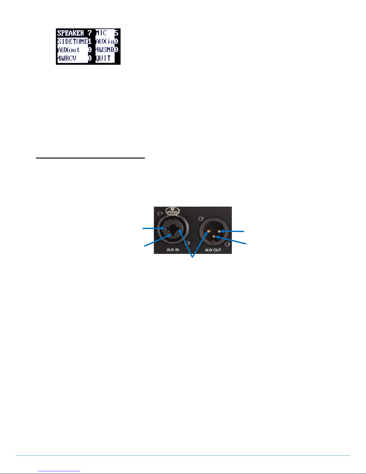
Step 1: When you use auxiliary device, such as another intercom or other audio sources, put its output cable connector into the
AUX IN connector (#19) and its input cable connector into the AUX OUT connector (#20), as the following pin connections.
The AUX OUT and AUX IN connectors are 3-pin XLR type for balanced +20dBV (10V) maximum level.
Figure 5-8. AUX IN and AUX OUT Connectors
Step 2: Activate the auxiliary input or auxiliary Input /Output connection and set the Communication Group
AUX BUTTON
There are two lights on top of the AUX button (#5). By pressing the AUX button sequentially, you can select auxiliary input
(AUX IN) only or auxiliary input and output (AUX I/O) at the same time or neither of them. Both lights should go off when
you inactivate the external auxiliary device.
AUX COMMUNICATION GROUP BUTTON
Communication Groups in the Base Station are set as “1” (Group 1) by default. Press auxiliary Communication Group
button (#6) and select Communication Groups (1, 2, 3, 4, 5 or A) for auxiliary device by pressing SET on each
Communication Group number. The Communication Group will be changed from “1” to “5”, and to “A” (All) by each
pressing. The Communication Group “1” will come again after “A” (All). Selected auxiliary Communication Group will be on
NORMAL Menu, as shown in Figure 3-3: When the Base Station or Belt Packs set a same Communication Group as that
of the auxiliary device, they can communicate with the auxiliary device.
Step 3: To adjust the auxiliary input volume level, under the MAIN menu of the Base Station‟s front panel display, move to and
select VOLUME. Then the VOLUME menu appears, as shown in Figure 5-9:
Pin 1
Pin 3
Pin 2
Pin 1
Pin 3
Pin 1 : Ground
Pin 2 : Audio +
Pin 3 : Audio –
Page 40
ⓒ2016 LaON Technology Co., Ltd. All rights reserved. 39
Under the VOLUME menu, move to and select AUXin which will lead you to volume values. You can change values by UP
or DOWN button. Listen to the audio input in your headset and adjust the auxiliary receiving level. After adjusting the level,
press SET, Move to AUXout and press SET button which will lead you to volume values. You can adjust auxiliary sending
level in the same way. While speaking into your headset microphone, adjust the auxiliary sending levels to the desired
listening level. Pressing SET for 2 seconds will lead you to the Normal menu.
EXTERNAL SPEAKER SETUP
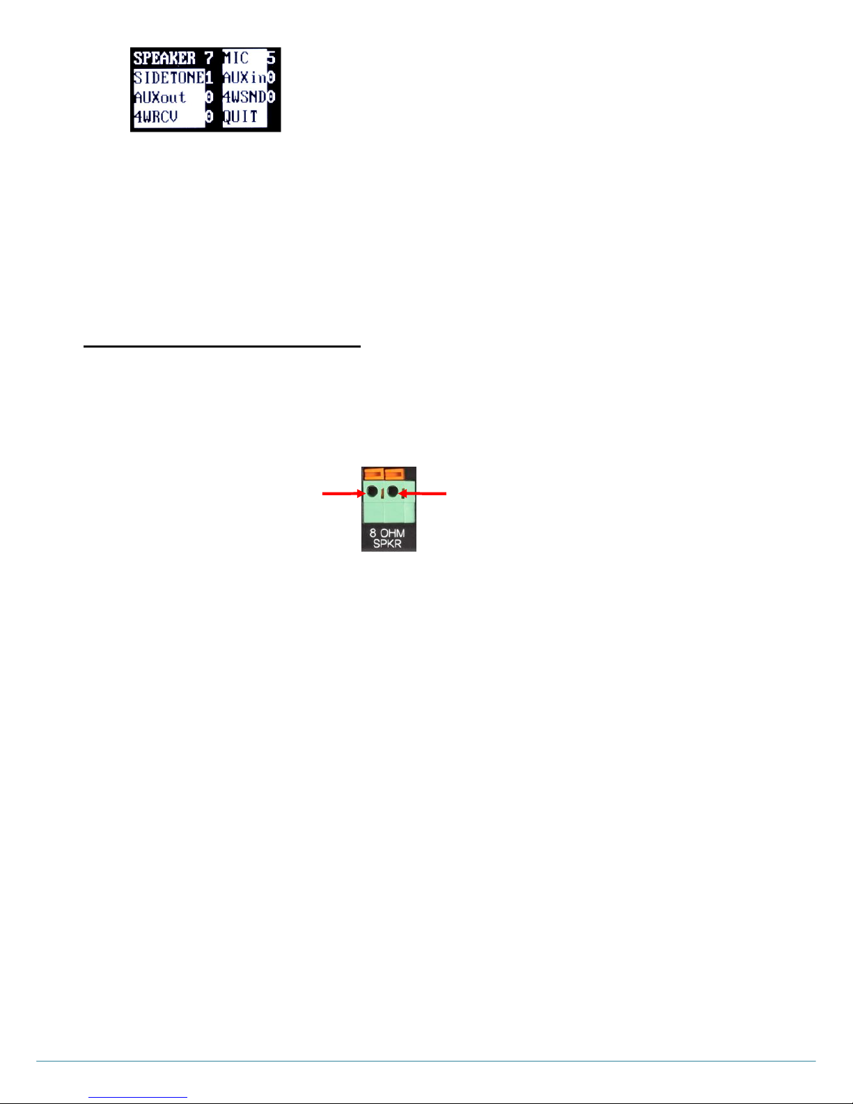
Step 1: When you use external 8 ohm speaker, connect its cable wire to the 8 OHM SPKR 2-pin Spring Clamp connector (#24) on
the rear panel of the Base Station, as the following pin connections. To plug a cable wire into the 2-pin spring clamp
connector, push and hold an orange-colored wire-release latch on the top of the connector, then put a cable wire into its
applicable pin and release a wire-release latch.
Figure 5-10. 8 OHM SPKR 2-pin Spring Clamp connector
Step 2: To adjust the speaker volume, under the MAIN menu of the Base Station‟s front panel display, move to and select VOLUME.
Then the VOLUME menu appears. Under the VOLUME menu, move to and select SPEAKER will lead you to volume
values. You can change the levels with UP or DOWN button.
VOLUME UP ADJUSTMENT
Every time you press the volume up button, a beep sound will be heard from the external speaker. When the level is
reached out to the maximum, a voice prompt, “maximum” will be heard from the external speaker.
VOLUME DOWN ADJUSTMENT
Every time you press the volume down button, a beep sound will be heard from the external speaker. When the level is
reached out to the minimum, a voice prompt, “minimum” will be heard from the external speaker.
NOTE: Either a headset speaker or an external speaker can be used; The SPEAKER volume is for adjusting the volume
of both.
Pin 1
Pin 2
Pin 1: Audio +
Pin 2: Audio -
Figure 5-9. VOLUME menu
Page 41
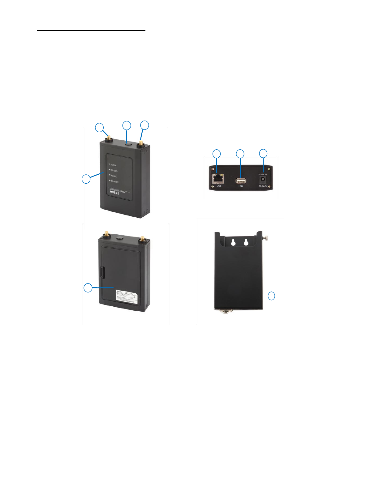
ⓒ2016 LaON Technology Co., Ltd. All rights reserved. 40
REMOTE STATION SETUP
A Remote Station (RBS) can be connected to the Base Station through LAN, composing customized and extended coverage, and
enabling automatic roaming between coverage zones. The Remote Station supports communication with Belt Packs in remote area
from the Base Station. Standard STP cable is used to connect the Remote Station either directly to the LAN port on the rear panel
of the Base Station or via the Network Switch. Remote Station can be powered by local electricity or batteries or network switching
device which has the Power-over-Ethernet (PoE) function. Remote Station shares up to eleven full duplex audio paths with the
Base Station within the coverage area. Up to five (5) Remote Stations can be connected to the Base Station. It is recommended to
compose the network exclusively for LaON intercom system. If the existing network at the site is used there could possibly a
network traffic, delay, audio breakups and etc in the wireless intercom communications.
1. ANTENNA connector
7. 12VDC POWER connector
2. ANTENNA connector
8. Cover
3. Null
9. Remote Station holder (optional)
4. Status lights
5. LAN RJ-45 connector with the PoE function.
6. USB connector
6
5
7
1
2 4 3
8
9
Figure 5-11. Remote Station and RBS Holder
Page 42
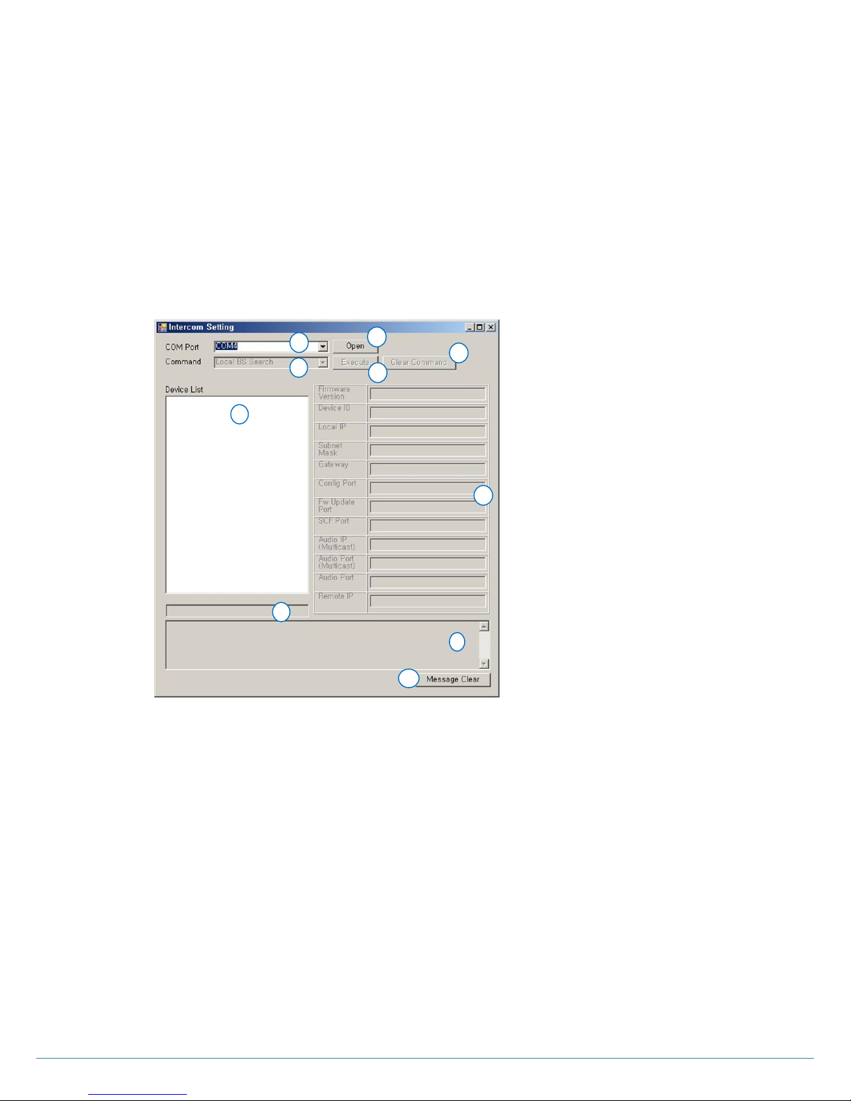
ⓒ2016 LaON Technology Co., Ltd. All rights reserved. 41
The instructions for the Remote Station setup and installation will be followed as below order. Take enough cautions for notes.
1. IP network information setup – Not required to compose an exclusive network
2. Pairing with the Base Station
3. Network configuration for the Base Station and Remote Station
4. Coverage test
5. Remote Station installation and notes
Step 1: IP Network information setup with a configuration tool program. (This is not required if an exclusive network is composed)
Download the LAON provided configuration tool program „LXSetting.exe‟ on your PC and connect the PC with the Base
Station through USB cable. Run the program on your PC and set up IP Network information required as following
instructions.
CONFIGURATION PROGRAM MAIN DISPLAY
1. Serial port selection window
6. Devices display window – BS and Remote Station
2. Serial port Open/Close button
7. Command execution result display window
3. Command execution button
8. Network information display window
4. Clear button for the executed Command
9. Additional message display window
5. Command selection drop down menu and display
window
10. Additional message delete button
1
2 6 4
3
7
8
5
Figure 5-12. Main display of the configuration tool program
9
10
Page 43
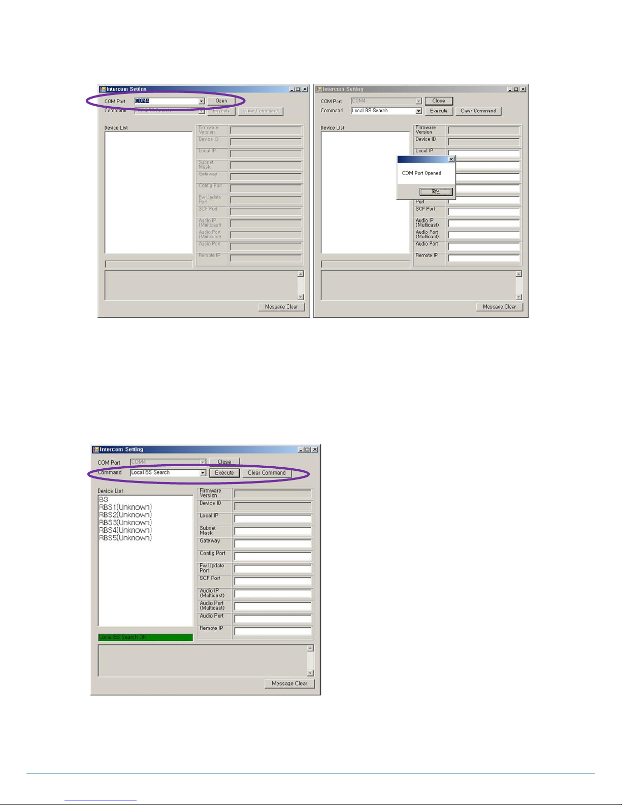
ⓒ2016 LaON Technology Co., Ltd. All rights reserved. 42
1) COM PORT OPEN
Select the COM port being used on the PC from the drop down menu. Click „Open‟ then, the pop up message „COM
Port opened‟ will be displayed if the correct port is selected as shown in the Figure 5-13.
2) DEVICE SEARCH
From the „Command‟ selection drop down menu, click „Local BS Search‟ and „Execute‟ button. Then, the Base Station
(„BS‟) being connected with the PC through USB cable will be detected in the „Device List‟ window. Also, Remote
Station („RBS‟) list will be followed as shown from the Figure 5-14.
Figure 5-14. Device Search
Figure 5-13. COM Port Open
Page 44
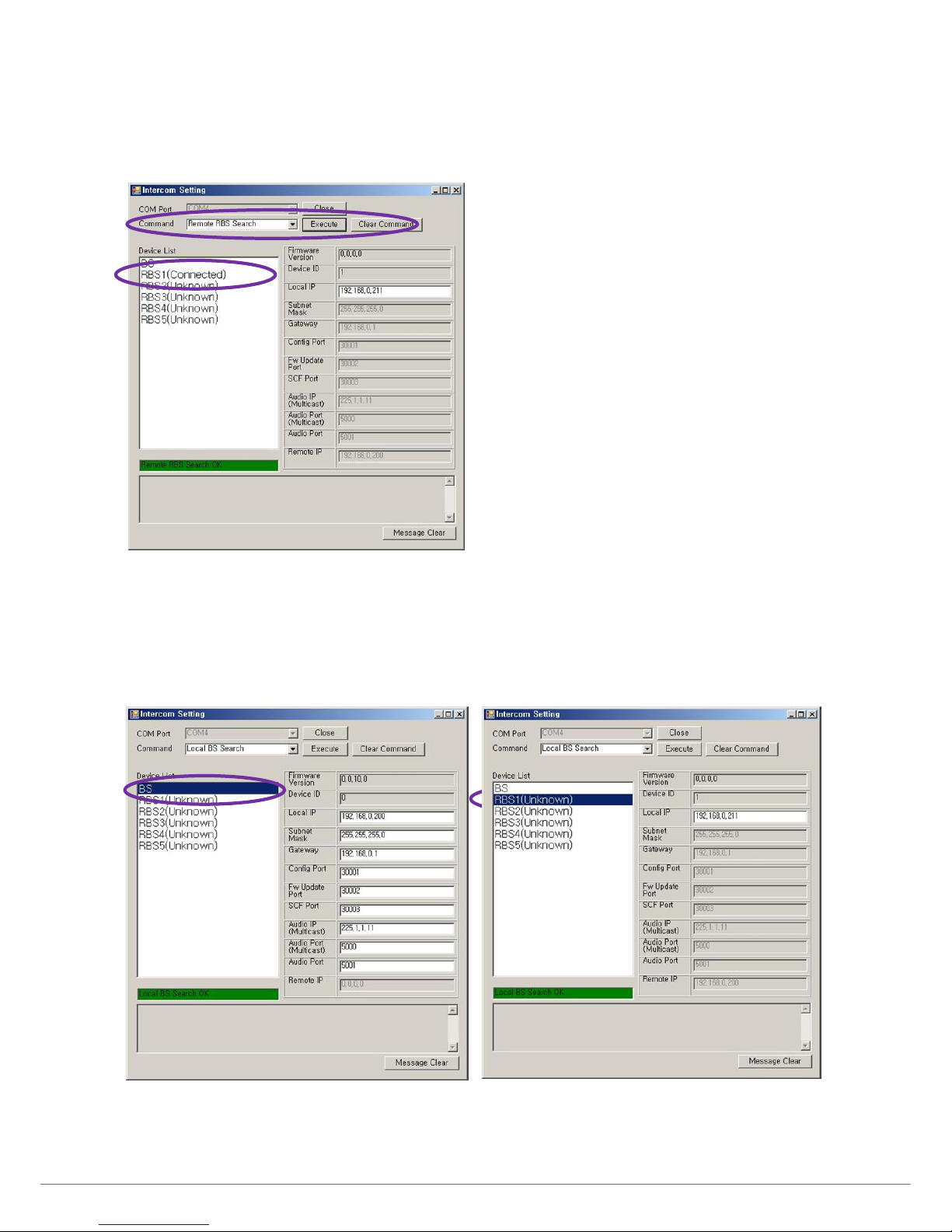
ⓒ2016 LaON Technology Co., Ltd. All rights reserved. 43
3) RBS CONNECTION STATUS
To confirm the Remote Station connection status, select the applicable Remote Station to confirm from the „Device
List‟ and select „Remote RBS Search‟ from the „Command‟ selection drop down menu and click „Execute‟ button then,
the network connection status will be displayed as „Connected‟ or „Disconnected‟ as shown from the Figure 5-15.
4) NETWORK INFORMATION DISPLAY
Select a device, BS or a RBS to display the Network information details of the applicable device as shown from the
Figure 5-16.
Figure 5-16. Network information display
Figure 5-15. RBS connection status
Page 45
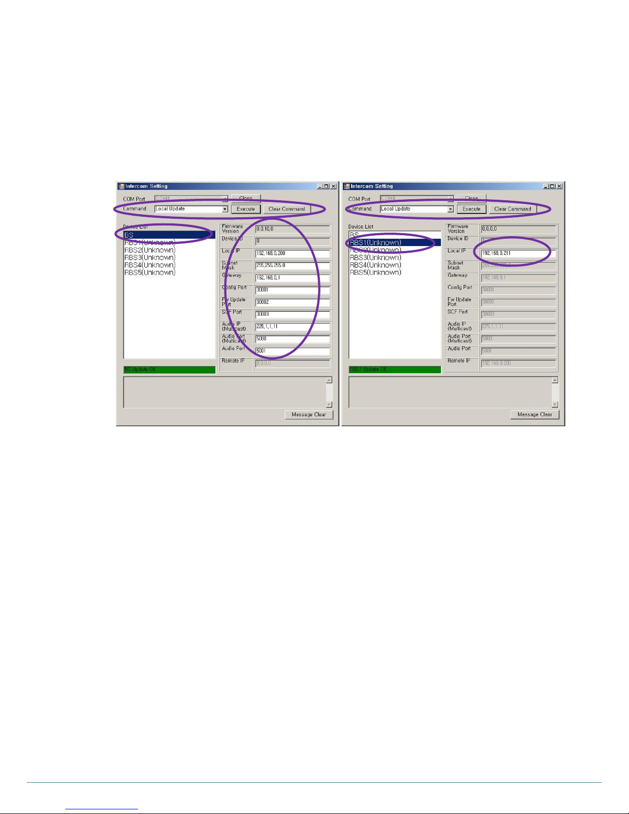
ⓒ2016 LaON Technology Co., Ltd. All rights reserved. 44
5) NETWORK INFORMATION SET UP OR UPDATE FOR BASE STATION
In order to update BS‟s network information, select „BS‟ from the „Device List‟ and edit the value as required. Select
„Local Update‟ from the „Command‟ selection drop down menu and click „Execute‟ button to complete the update. As
updating the BS network information, back to back RBS network information will be updated accordingly.
In order to update RBS‟s network information being set up at the BS, select the desired RBS for update from the
„Device List‟ and edit information. Then, select „Local Update‟ from the „Command‟ selection drop down menu and
click „Execute‟ button to save as shown from the Figure 5-17.
In order to update the network information for RBS end, you may implement RBS pairing up process following the
Step 2 below.
All the log data of updated information will be saved in the same directory of „LXsetting.exe‟ as „LXsetting.txt‟, if the
updates are done properly. Click „Close‟ button to close the „COM Port‟ and configuration tool program.
NOTE: In order to update the network information for RBS which is already in paired mode, you may implement either
RBS pairing up process again or process it in this program with „Remote RBS Update‟ command as following
instruction.
All the devices including the applicable RBS for update should be connected to perform this process.
NETWORK INFORMATION UPDATE FOR REMOTE STATION WHICH IS IN PAIRED MODE
Select the desired RBS for update from the „Device List‟ and select „Remote RBS Update‟ from the „Command‟ selection
drop down menu. Edit the network information and click „Execute‟ button to save the update as shown from the Figure 5-
18. Reboot all devices after updates.
Figure 5-17. Local network information update for BS
35
Page 46
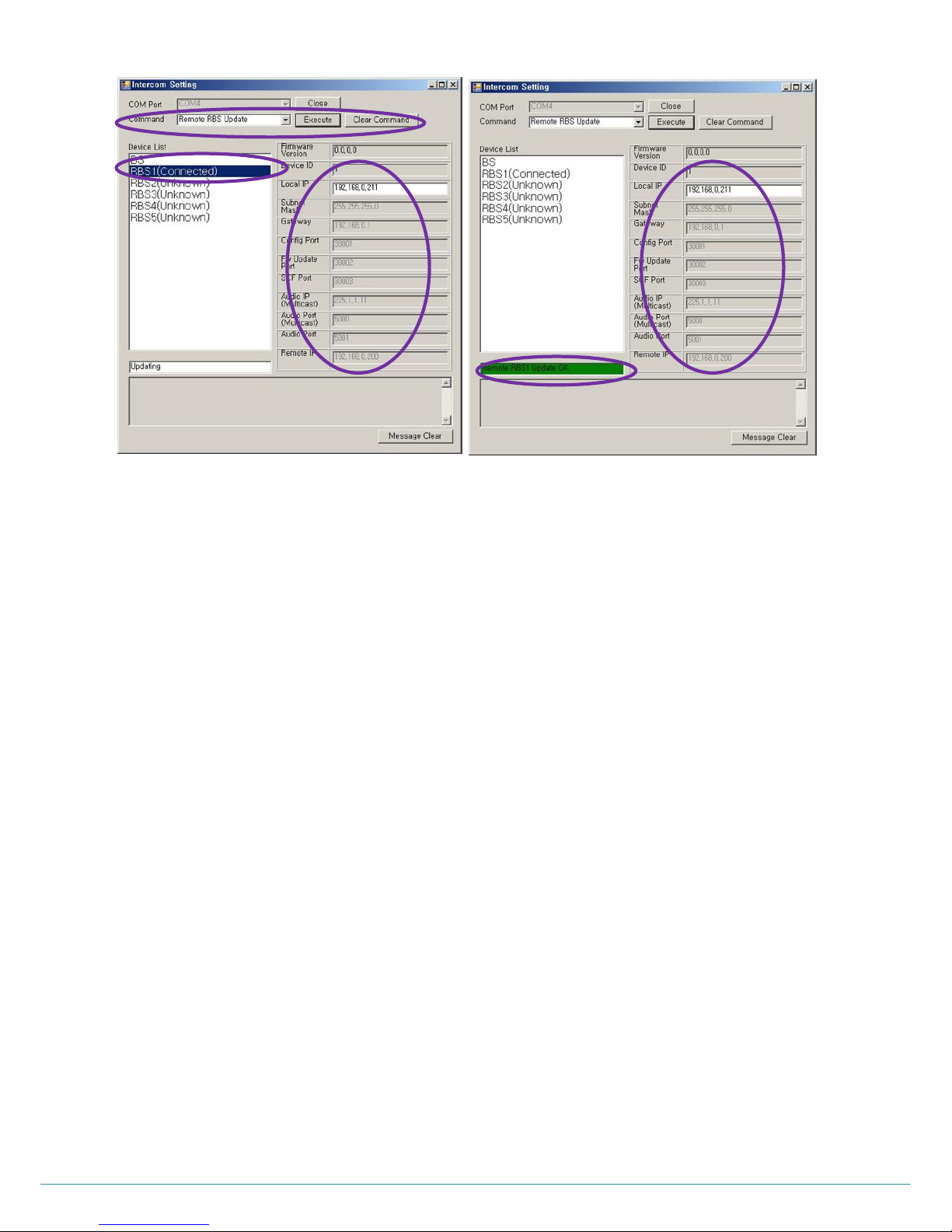
ⓒ2016 LaON Technology Co., Ltd. All rights reserved. 45
NOTE 1: After executing the configuration program, reboot the Base Station.
NOE 2: In case updating the Remote Station setup information through network
After updating the setup information of the Base Station and Remote Sation which are stored in
the Base Station („Local BS Update‟), Network update („Remote RBS Update‟) should be done.
If the update is not done for the Local BS, only the changed information of the Remote Station will
be updated and previous information will be left in the Base Station
No need to reboot the Remote Station.
NOTE 3: Confirm the Network setup values
When connecting into the non-exlusive exisiting network at the customer site, assigned IP and port
information of the Base Station and Remote Station should be set correct.
Step 2: Paring up the Remote Base Station with Base Station
Once the IP network information setting is completed, disconnect the PC from Base Station and reboot the Base Station.
For pairing up process, the Remote Station should be connected direct to the Base Station through standard STP LAN
cable. Implement paring up process for each of the Remote Station one by one.
1) REMOTE STATION SET UP
Put two enclosed antennas into the antenna connectors (#1 and #2) on the top panel of the Remote Station. Turn the
sleeve on each of the antenna connectors clockwise to tighten them and ensure that the antennas are connected firmly.
NOTE: When attaching the antennas directly to the top panel of the Remote Station, the Remote Station should be away
from any metal obstructions, walls and electronic equipments that can create radio interference. When actually installed at
site it is highly recommended to place the antenna as high as possible in the center of the coverage and away from
obstructions.
Figure 5-18. Network information update for RBS which is in paired mode
Page 47
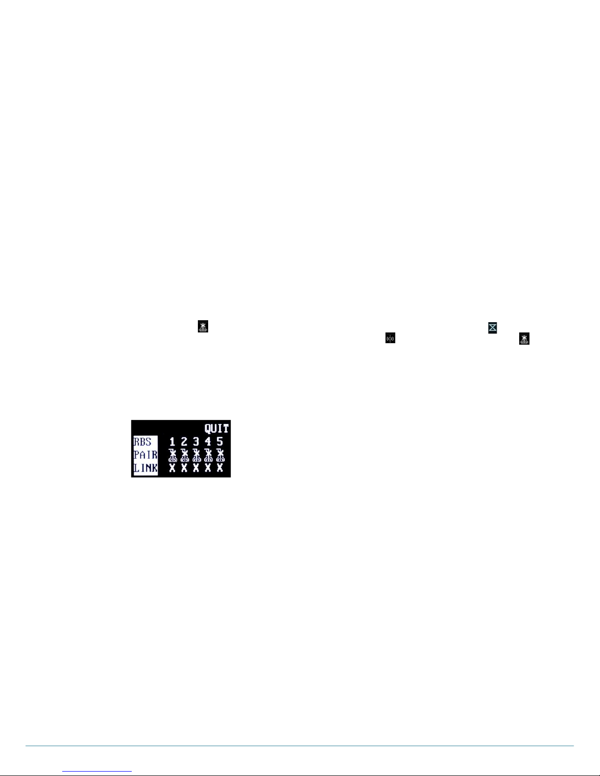
ⓒ2016 LaON Technology Co., Ltd. All rights reserved. 46
2) WIRE REMOTE STATION WITH BASE STATION
Put the STP cable into the Base station‟s LAN RJ-45 Connector, and the other side into the Remote Station‟s LAN RJ-45
Connector (#5) as shown in Figure 5-11. For pairing, single Remote Station o be paired up should be connected at once.
3) SUPPLY POWER TO THE REMOTE STATION
When you use the wall-adapter power supply:
Plug the DC cable from the enclosed wall-adapter power supply into the 12VDC POWER connector (#7) on the
bottom of the Remote Station. Plug the large female connector at the end of the AC power cord into the power
supply and plug the other end of the AC power cord into a standard wall outlet.
When you use the battery:
Pull the cover up to open the battery cover (#8) and put a fully charged rechargeable battery pack (BAT150) or
battery sled with six fresh AA 1.5v alkaline batteries. Make sure the position of polarity (+, -) is correct.
When you use the network switching device which has the PoE function:
Connect STP cable to LAN Connector (#5) of Remote Station and connect the other side to network switching
device which has the PoE function.
Upon the power supply, the green light should go on. In case of using battery, when the battery level is low, red light will go
on.
4) IMPLEMENT THE PARING UP PROCESSING
On the MAIN menu of the Base Station, move to and select “RBS”. The RBS menu appears as shown in Figure 5-19.
Move to the applicable Remote Station number for paring up by pressing LEFT or RIGHT and press SET then, the
corresponding pairing icon, ( ) in the next row of the applicable Remote Station number is changed to ( ), indicating
the paring is being processed. If paring processing is completed successfully, ( ) icon is displayed and if failed, ( ) is
displayed. Repeat the same process one by one for additional Remote Stations.
When the paring processing is completed between Base Station and Remote Station, the RBS LINK light on the front
panel of the Base Station will go on and the RBS Active light will be blinking when there are data transmissions.
Reboot all the Remote Stations once the pairings for the Remote Stations to be in use are all done. And then reboot the
Base Station with the toggle power switch.
NOTE 1
The RBS LINK light on the Base Station will go on if there is more than one Remote Station linked in.
NOTE 2
The link status of the multiple Remote Stations can be monitored in the RBS menu as shown in the Figure 5-19. When the
Remote Station is linked in, “O” is displayed and not linked, “X” will be displayed.
NOTE 3
During the pairing process, all the connections for communications will temporarily halted.
Step 3: Wire the Base Station with Remote Stations for actual operation as shown from the Figure 5-20
Figure 5-19. RBS menu
Page 48
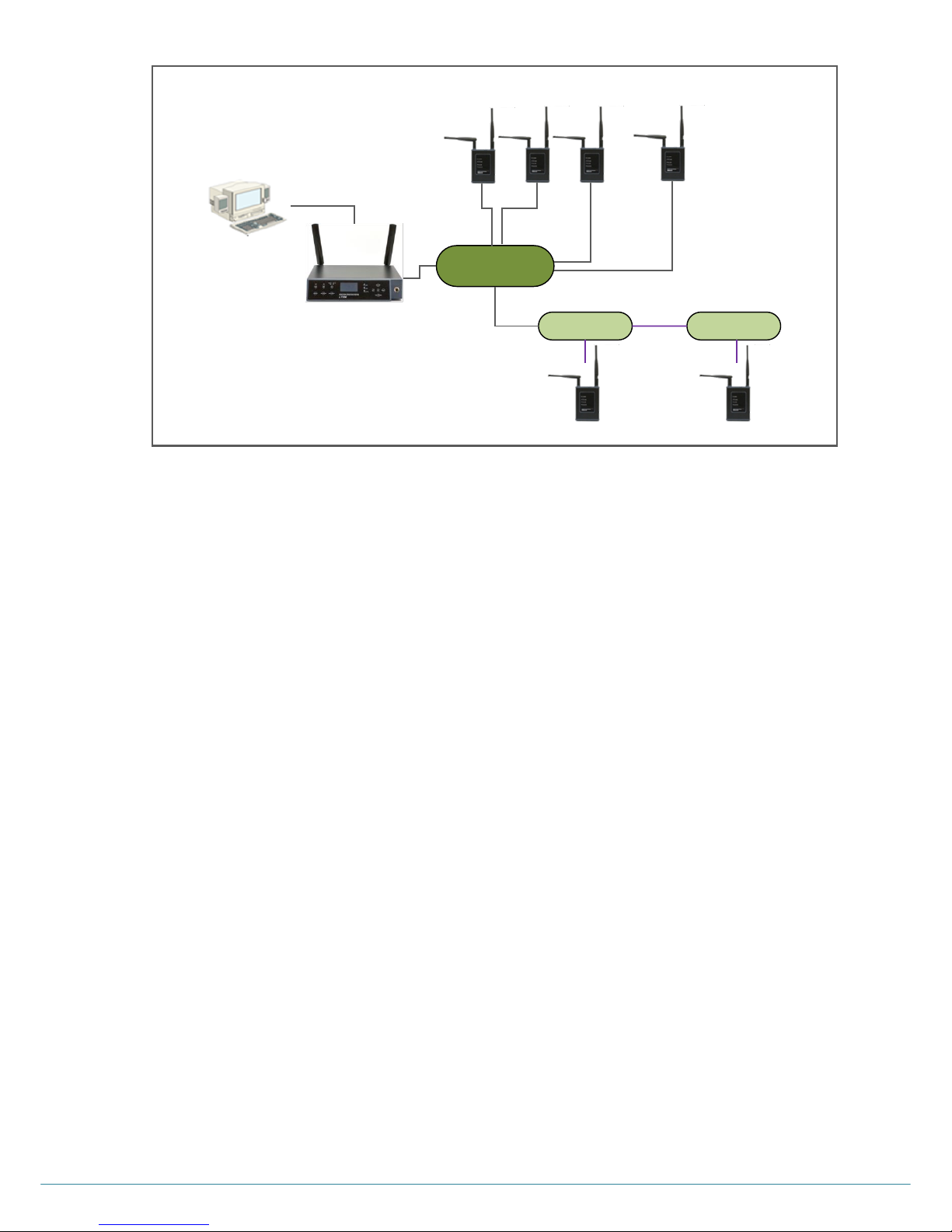
ⓒ2016 LaON Technology Co., Ltd. All rights reserved. 47
Above is an example of the basic system configuration. Since the connection between the Remote Station and Base
Station follows the standard LAN network configuration method, the system can be configured with full flexibility with PoE
repeaters as well as network switches. Also, the coverage can be expanded by adapting daisy chain connection, fiber
optic cable, wireless bridge and etc.
NOTE: Not using dedicated exclusive network between the Base Station and the Remote Stations, there could possibly
be delays due to network traffic. When there are audio breakups due to the delays, it is highly recommended to compose
a dedicated exclusive network. „Dedicated Network‟ means the LAN network is used only for the LaON Base Station and
Remote Stations.
STATUS LIGHTS ON THE FRONT PANEL OF THE REMOTE STATION
RF ALERT light
When there are audio breakups seriously, RF ALERT light will go on.
BS LINK light
When the Remote Station is connected to the Base Station, BS LINK light will go on.
BS ACTIVE light
When the Remote Station exchanges data with the Base Station, BS ACTIVE light will be flashing.
Step 4: Perform the coverage test
Once the Remote Station is located at a space, you can test the coverage to find out optimal location of the Remote Stations.
TESTING COVERAGE AREAS
Checking Received Signal Strength Indication Level
Once the Base Station and Remote Stations are properly connected and the pairing is done, turn on the Belt Pack power
and check out within the coverage area while walking around the Base Station or Remote Station. While talking and moving
around, check audio breakups and Received Signal Strength Indication („RSSI‟)(„A‟) level on the Belt Pack‟s NORMAL
menu, as shown in Figure 5-21:
Figure 5-20. Connection example
Network Switch
(PoE)
PoE Repeater
PoE Repeater
USB
STP
Cable
…
Page 49
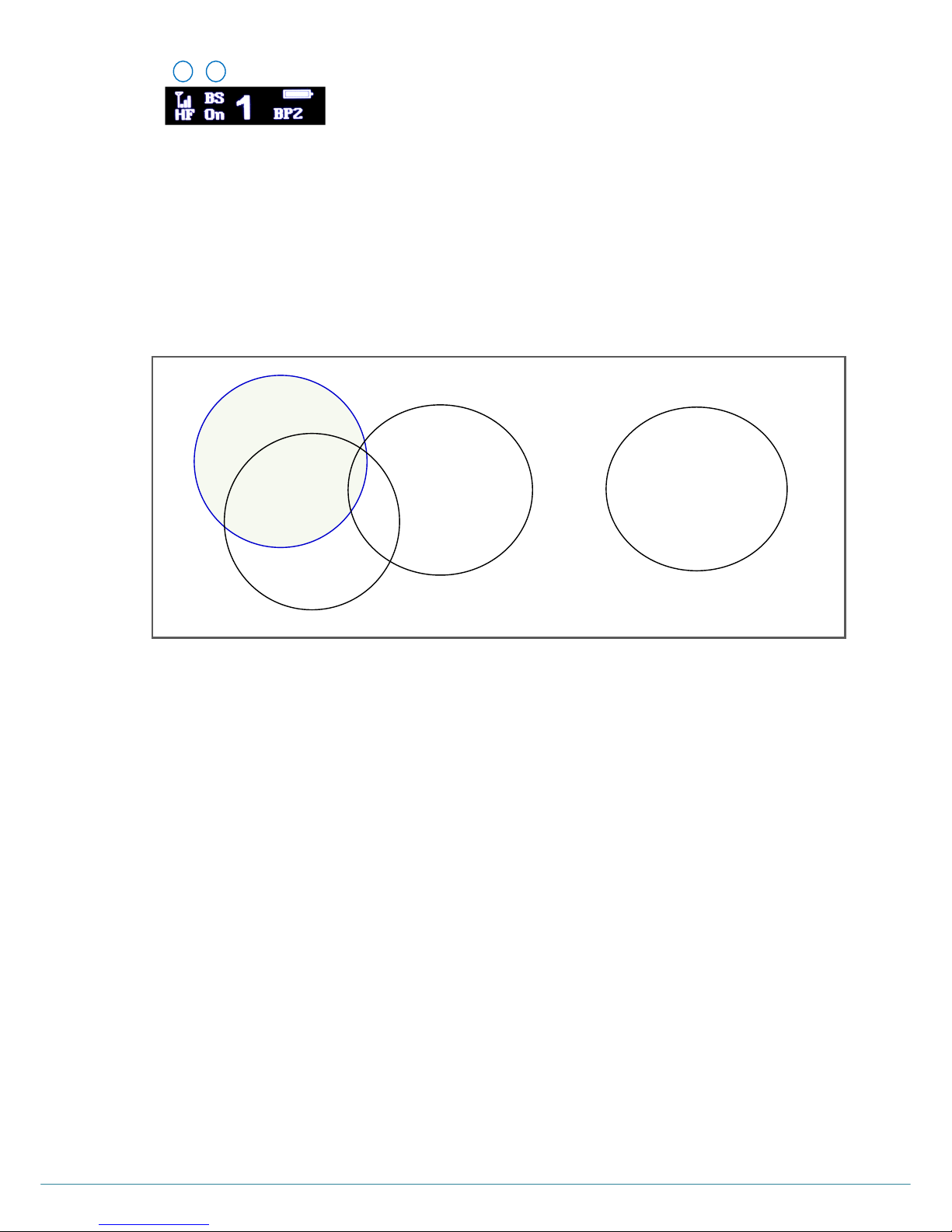
ⓒ2016 LaON Technology Co., Ltd. All rights reserved. 48
If RSSI Graphic bar is less than one and audio breakups start, that is the limit of coverage zone.
Mapping coverage zones
Draw a map of the coverage zone for the antenna of the Base Station and Remote Station as shown in Figure 5-22: While
repeating this process, see if the Base Station and Remote Station cover each area enough. If not, add the required
number of additional Remote Stations. In order to secure enough overlapping area, locate the Remote Station like a
coverage zone A and B creating enough overlapping area and set the „Hands off Sensibility‟ level as „High‟ or „Mid‟ on the
menu screen of the Belt Pack which will make the roaming quickly. In normal case, locating the Remote Stations like the
coverage zone A, C & D where the Belt Pack communication is required would be feasible.
Figure 5-22. Mapping coverage zones
Relocation of the Base Station and Remote Station
In a certain environment, audio breakups could occur even though high signal strength is observed.
There might be two reasons as followings:
A Belt Pack is within 6.5 feet (2 meters) from the antenna that of the Base Station or the Remote Station.
RF signals reflection could occur in an environment where there are a number of reflective surfaces, such as metal
obstructions, walls or other large structures and electronic equipments that can create radio interference.
You can relocate the Base Station or Remote Station antenna to avoid reflective surface. It is highly recommended to
relocate the antenna as high as possible in the center of the coverage and away from obstructions.
Testing antenna Handoff
After testing the coverage zones of the antennas that of the Base Station and Remote Stations, you should continue to test
handoff between the coverage zones. When your Belt Pack is out of coverage while walking through coverage zones, the
Belt Pack scans to find another antenna of the Base Station or Remote Station and automatically roam to the antenna with
the stronger signals. When the automatic roaming is performed smooth while walking through Zone A and Zone C, the
distance between the antenna locations of the Base Station and Remote Station maybe ideal. In order to confirm the Belt
Pack is connected to which of the Base Station or Remote Stations, see Belt Pack‟s NORMAL menu, („B‟), as shown in
Figure 5-21. If the Belt Pack is connected to the Base Station, “BS” will appear. If a Belt Pack is connected to the Remote
Station, a Remote Station‟s ID number “R1” through “R5” will appear. You can also monitor the Belt Pack status on the Base
Station‟s MONITOR menu, as shown in Figure 5-23. The MONITOR menu shows each Belt Pack is connected to which of
the Remote Stations or the Base Stations.
A
B
Figure 5-21. Belt Pack‟s NORMAL Menu
A. RSSI level
B. Base Station or Remote Station that the Belt Pack is being connected
Zone A
BS
Coverage Area
Zone B
RBS1
Coverage Area
Zone D
RBS3
Coverage Area
Zone C
RBS2
Coverage Area
Page 50
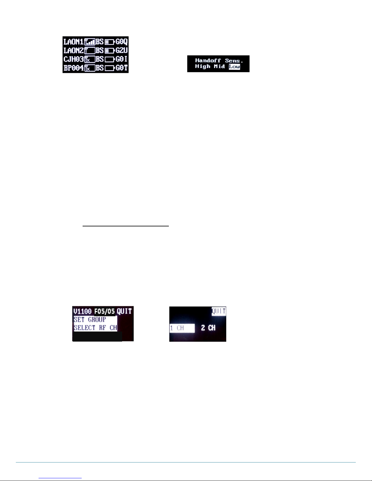
ⓒ2016 LaON Technology Co., Ltd. All rights reserved. 49
In case wide overlapping area is created like between the coverage zone A, B and C Zone A, Zone B, Zone C, set the
„Hands off Sensibility‟ level as „High‟ or „Mid‟ on the menu screen of the Belt Pack which will make the handoff quickly.
When using the Belt Pack in an independent area like the coverage zone D, set the „Hands off Sensibility‟
level as „Low‟ on the menu screen of the Belt Pack then the communication will be disconnected only when the Belt
Pack is totally out of the coverage.
The user can manually execute the hand-off by a „double click‟ of the power button on the front panel of the Belt Pack.
Expect a beep sound upon the new link to other Base Station or Remote Stations.
NOTE:
When manually roaming, do not press PWR button longer than 2 second otherwise, the Belt Pack will be turned off.
In case of doing a manual roaming operation, depending on the site environment and condition of installation - for an
instant, when moving from the coverage zone C to D, the Belt Pack could be totally out of coverage with a voice
message from headset with the red LED blinking and then roamed to another coverage zone with the green LED on.
See the “ BS550 BASE STATION OPERATION” in SECTION 4 for the details about MONITOR menu.
PRECAUTIONS UPON SETUP AND INSTALLATION OF THE REMOTE STATION
1) Frequency diversity options
In order to save frequency band or to avoid any possible interferences when there are multiple Remote Stations located, it is
recommended to not select the frequency diversity option 2CH.
Move to BS menu and select SELECT RF CH. From the two options, select 1CH.
Figure 5-23. MONITOR menu on Base Station
Figure 5-24. HANDSOFF SENSIBILITY
level selection menu on Belt Pack
Figure 5-25 „BS‟ menu
Figure 5-26 „SELECT RF CH‟ menu
Page 51

ⓒ2016 LaON Technology Co., Ltd. All rights reserved. 50
2) Frequency monitoring
Through a USB port connection with the Base Station, the frequency channel currently being taken of the Base Station
and Remote Stations can be monitored. The frequency ID indicated in this program is followed as below figure 5-27.
In case the same frequency is taken by Bas Station and Remote Station, or Remote Stations which are neighboring, try to
reboot the Base Station with the power toggle switch to make all the system rescan the frequencies, or reboot the
applicable Remote Station to rescan for the better frequency.
FREQUENCY BAND
The following lists the frequencies that can be used in 5GHz UNII band. The ID of frequency bands currently being used
will be shown on the BS menu. The LT550 system which operates in 5GHz is approved for license free use in most
countries. However, some countries may restrict the use of some band or RF spectrum operations. Therefore, it is your
responsibility to find out whether the LT550 system is permitted in your country or not.
Figure 5-27. Frequencies being used in 5GHz UNII band
3) Precautions to install multiple Remote Stations
Upon installation of multiple Remote Stations, fully aware of the followings to feasibly install and use the system with the
full use of automatic avoidance function against any possible frequency interference.
Turn on the Remote Station and Base Station in designated order as below.
Firstly, supply the power source to all Remote Station in connection. When using a PoE switch, supply the
power to the PoE switch or if it is already done, connect the LAN cable between the Remote Station and
the PoE Switch through a PoE Port.
Then, turn on the Base Station.
Assuming that five (5) Remote Stations are installed at the site. After the NORMAL menu screen is
displayed on the Base Station, Base Station starts to scan the best available frequency channels one and
after sequentially for all Remote Stations from R1 to R5. The power LED of the Remote Station that is in
the scan mode with the Base Station will be changed to RED on. Once the scanning process is completed,
„BS LINK‟ LED will be on in green indicating the link between the Base Station and Remote Station is done.
At the Base Station end, the Remote Station link status can be confirmed from the RBS menu. For the
scanning process of the five (5) Remote Stations, 100 seconds – 20 seconds per Remote Station) will take.
Frequency ID
Channel
Frequency
Band width
US
EU
Japan
Korea
01
52
5260MHz
20MHz
O O O
X
02
56
5280MHz
20MHz
O O O
O
03
60
5300MHz
20MHz
O O O
O
04
64
5320MHz
20MHz
O O O
O
05
100
5500MHz
20MHz
O O O
O
06
104
5520MHz
20MHz
O O O
O
07
108
5540MHz
20MHz
O O O
O
08
112
5560MHz
20MHz
O O O
O
09
116
5580MHz
20MHz
O O O
O
10
120
5600MHz
20MHz
X O O
O
11
124
5620MHz
20MHz
X O O
O
12
128
5640MHz
20MHz
X O O
X
13
132
5660MHz
20MHz
X O O
X
14
136
5680MHz
20MHz
O O O
X
15
140
5700MHz
20MHz
O O O
X
16
149
5745MHz
20MHz
O X X
O
17
153
5765MHz
20MHz
O X X
O
18
157
5785MHz
20MHz
O X X
O
19
161
5805MHz
20MHz
O X X
O
20
165
5825MHz
20MHz
O X X
O
Page 52
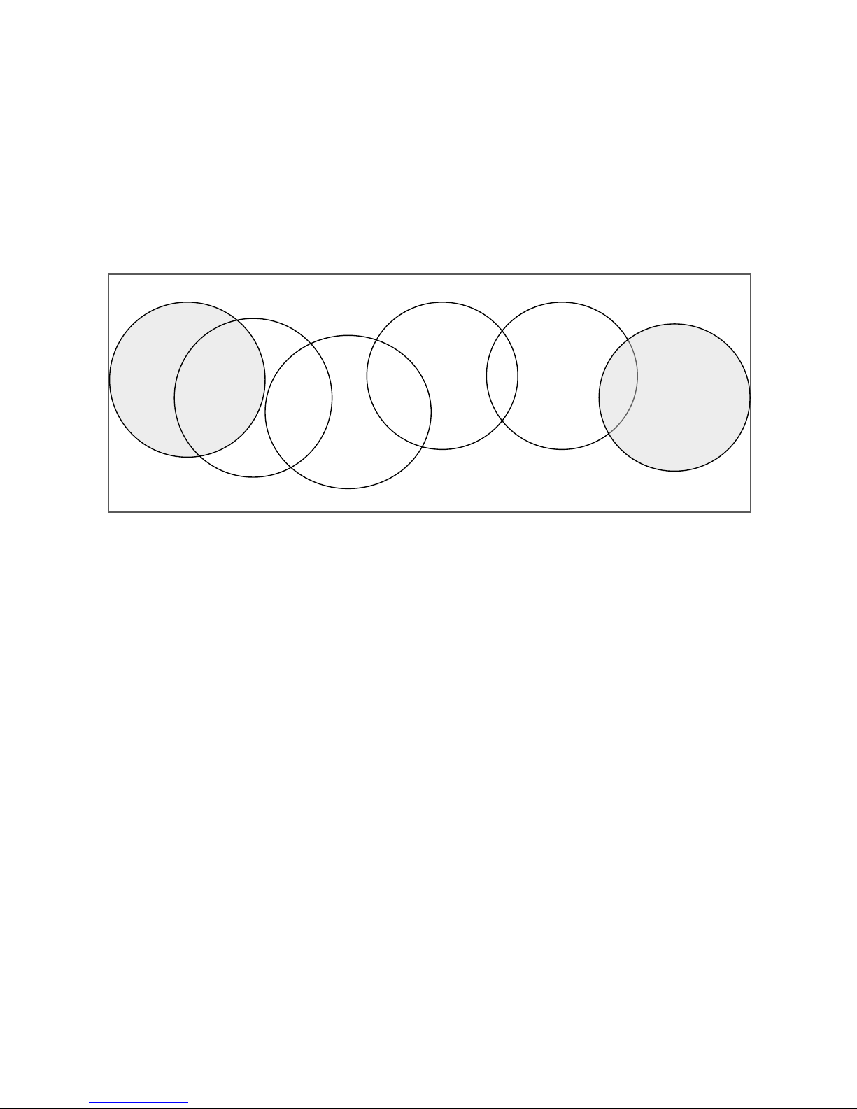
ⓒ2016 LaON Technology Co., Ltd. All rights reserved. 51
NOTE: If the Base Station is turned on before the Remote Station, it is impossible for Remote Stations to receive
correct data regarding the sequential power on and automatic frequency avoidance which may cause
inefficient frequency channel allocations. And Remote Stations may miss to receive the correct frequency
avoidance information about other Remote Stations or Base Station and take the duplicated frequency. If it is
the case, while the Remote Stations are turned on, reboot the Base Station only with the power toggle switch
and make the system rescan properly.
Install the Remote Stations sequentially from the nearest location from the Base Station.
Locate the RBS1 at the nearest place from the Base Station, RBS2 at the next nearest place, and RBS5 the
farthest place as shown from the figure 5-28. By following this rule, the coverage zone A and G where no
interference between at all, can use the same frequency channel which is the way to fully enjoy the usable
frequency channels with efficiency.
Figure 5-28. Configuration example with overlapping of frequencies
Precautions when pairing between the Belt Pack and Remote Station
Do not make pairing for any Belt Packs or Remote Stations for 100 seconds after the NORMAL menu is
displayed on the Base Station
If any Belt Pack pairing is tried during this scanning process ;
Due to dramatic down of the TX power of the Base Station, there could possibly an issue that Remote Stations
are not able to scan frequency channels and in the result, they may occupy a duplicated frequency channel.
If any Remote Station pairing is tried during this scanning process ;
Pairing will not be completed properly.
Zone A
BS
Coverage Area
FREQ. 1
Zone D
RBS3
Coverage Area
FREQ. 7
Zone B
RBS1
Coverage Area
FREQ. 3
Zone C
RBS2
Coverage Area
FREQ. 5
Zone F
RBS4
Coverage Area
FREQ. 11
Zone G
RBS5
Coverage Area
FREQ. 1
Page 53

ⓒ2016 LaON Technology Co., Ltd. All rights reserved. 52
SECTION 6: FAQS AND TROUBLESHOOTING
BASE STATION
Regarding limited RF coverage
When there are audio breakups within the coverage
Ensure that the antennas are properly connected and tightened on the Base Station.
Confirm the antennas are positioned vertically and be folded completely as 90 degree.
Check around the Base Station‟s line-of-sight and ensure that there are no physical obstructions around. While attaching
the antennas directly to the rear panel of the Base Station, the Base Station should be away from any metal obstructions,
walls, and electronic equipments that can create radio interference. If possible, the antenna should be located as high as
possible and away from obstructions and select location to the center of the coverage.
When Remote Station or Stations are connected
Monitor if there is any duplicated frequency channel within the same range with LaON provided software program.
If any, reboot the Base Station with the power toggle switch on the Base Station while the Remote Station is turned on, or
reboot the applicable Remote Station only.
TALK light on the Base Station does not come on
Make sure that the power cords are properly plugged to the Base Station and standard wall outlet.
Confirm that the POWER switch on the rear panel of the Base Station is turned on.
No audio data TX/RX between a Base Station and an external hardwired intercom system
Make sure that the cables are firmly connected and the 4-wire or AUX intercom is on.
Confirm that the Base Station and 4-wire or AUX are in the same Communication Group.
Make sure that the headset is firmly connected to the Belt Pack or the Base Station.
Page 54

ⓒ2016 LaON Technology Co., Ltd. All rights reserved. 53
BELT PACK
Belt Pack TALK light does not turn on green and “out of coverage” is heard in the headset.
Confirm that the POWER switch is turned on and ensure that the battery is fully charged.
Reboot the Belt Pack and Base Station again.
Check out the coverage. You may be too far from the Base Station or the Remote Station. The coverage can be varied
depending on the site environments and basically the „line-of-sight‟ should be secured between the Base Station and Belt
Pack, or Remote Station and Belt Pack.
Communication is unable with single or multiple group channels
Confirm TALK button and light of the Base Station and Belt Pack
Check out if the correct communication group channel is selected
In case in „TWO GROUPS‟ mode, communication is available with the two (2) groups only
Communication or pairing is unable between the Base Station and Belt Pack
Confirm with the power toggle switch of the Base Station if the power is on
Make sure the two (2) antennas are properly and firmly connected to the Base Station
Make sure the headset is firmly connected to the Belt Pack
Check out if the pairing is made between the Base Station and Belt Pack
Check if the Base Station is TX ON mode in the Base Station menu screen
Audio breakups in the coverage
If the Belt Pack is near the Base Station or Remote Station however the RSSI level is low
In case multiple Remote Stations and Base Stations are existing in the range
Confirm the Belt Pack‟s link status in the NORMAL menu of the Belt Pack if it is connected to the nearest Base Station or
Remote Station. If it is connected to a Base Station or Remote Station in remote area, try to rescan the Base Station or
Remote Station with the stronger signal by a double click of the power button of the Belt Pack. And set the hands off
sensibility as „High‟ or „Mid‟ in HANDSOFF SENSIBILITY menu of the Belt Pack.
Monitor if there is any duplicated frequency channel within the same range with LaON provided software program.
If any, reboot the Base Station with the power toggle switch on the Base Station while the Remote Station is turned on, or
reboot the applicable Remote Station only.
In case of low battery
If the battery level is low, TALK light of the Belt Pack is changed to red. In case of low battery, it may cause a malfunction.
Replace the battery immediately with a fully charged battery or turn off the Belt Pack, or unlatch the Belt Pack from the
UNLATCH menu of the Base Station. In case of low battery, the TX and power is automatically off however continuous
using or pressing TALK button of the Belt Pack and etc may cause bad affection to the wireless communications for a
while.
Page 55

ⓒ2016 LaON Technology Co., Ltd. All rights reserved. 54
REMOTE STATION
Limited RF coverage
When there are audio breakups within the coverage
Ensure that the antennas are properly connected and tightened on the Remote Station
Confirm the antennas are positioned horizontally not being folded
Reflected RF signals could occur in an environment with a number of reflective surfaces, such as metal obstructions,
walls or other large structures, and electronic equipments that can create radio interference. You can relocate the Remote
Station antenna to avoid the reflective surface. If possible, you can adjust the antenna as high as possible and away from
any reflective obstructions and relocate them to the center of the coverage.
Monitor if there is any duplicated frequency channel within the same range with LaON provided software program.
If any, reboot the Base Station with the power toggle switch on the Base Station while the Remote Station is turned on, or
reboot the applicable Remote Station only.
The communication with Belt Pack is unable within the Remote Station‟s coverage
Ensure that the antennas are properly connected and tightened on the Remote Station
Check out the RBS LINK light on the front panel of the Base Station and BS LINK light on the front panel of the Remote
Station are on. Make sure that you have paired up a Remote Station with the appropriate Base Station.
If LINK lights are not on, check the Base Station‟s RJ-45 connector and Remote Station‟s RJ-45 connector are properly
wired to the network switch. Ensure that the network switch is working well.
If the power light on the front panel of the Remote Station is off; check the power cord is firmly connected or the PoE
network switch is working well.
Page 56
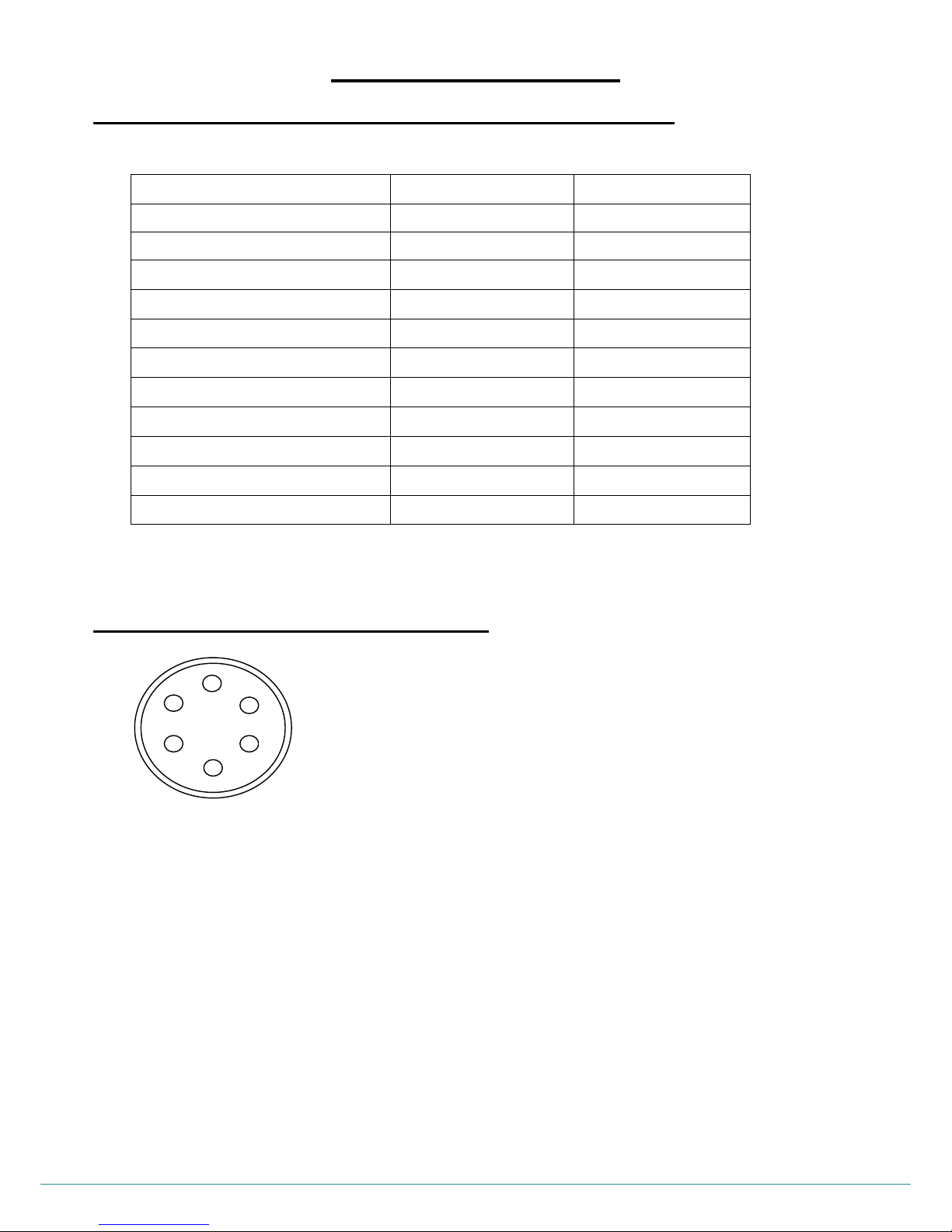
ⓒ2016 LaON Technology Co., Ltd. All rights reserved. 55
SECTION 7: APPENDIX
FACTORY DEFAULT SETTING AND RECOMMENDATION
6-PIN HEADSET CABLE CONNECTOR
1. MIC VCC +2V (For ECM mic.)
2. MIC – (GND)
3. MIC + (For Dynamic mic.)
4. MIC VCC +5V (For preamplifier mic. out)
5. RECEIVER -
6. RECEIVER +
Item
Base Station default
Belt Pack default
Microphone gain 5 5
Speaker volume
8
8
Communication Group Allocation
1,2,3,4,5 (All)
1,2,3,4,5 (All)
Communication Group Selection
1
1
„TALK‟ button
Unlatched
Unlatched
Hands free mode
On
On
Auxiliary In/Out connection On/Off
Off
NA
Auxiliary In/Out volume
8
NA
4-Wire connection On/Off
Off
NA
4-Wire send/receive level
8
NA
Hands off Sensibility
NA
MID
1 2 3 4 5
6
Page 57
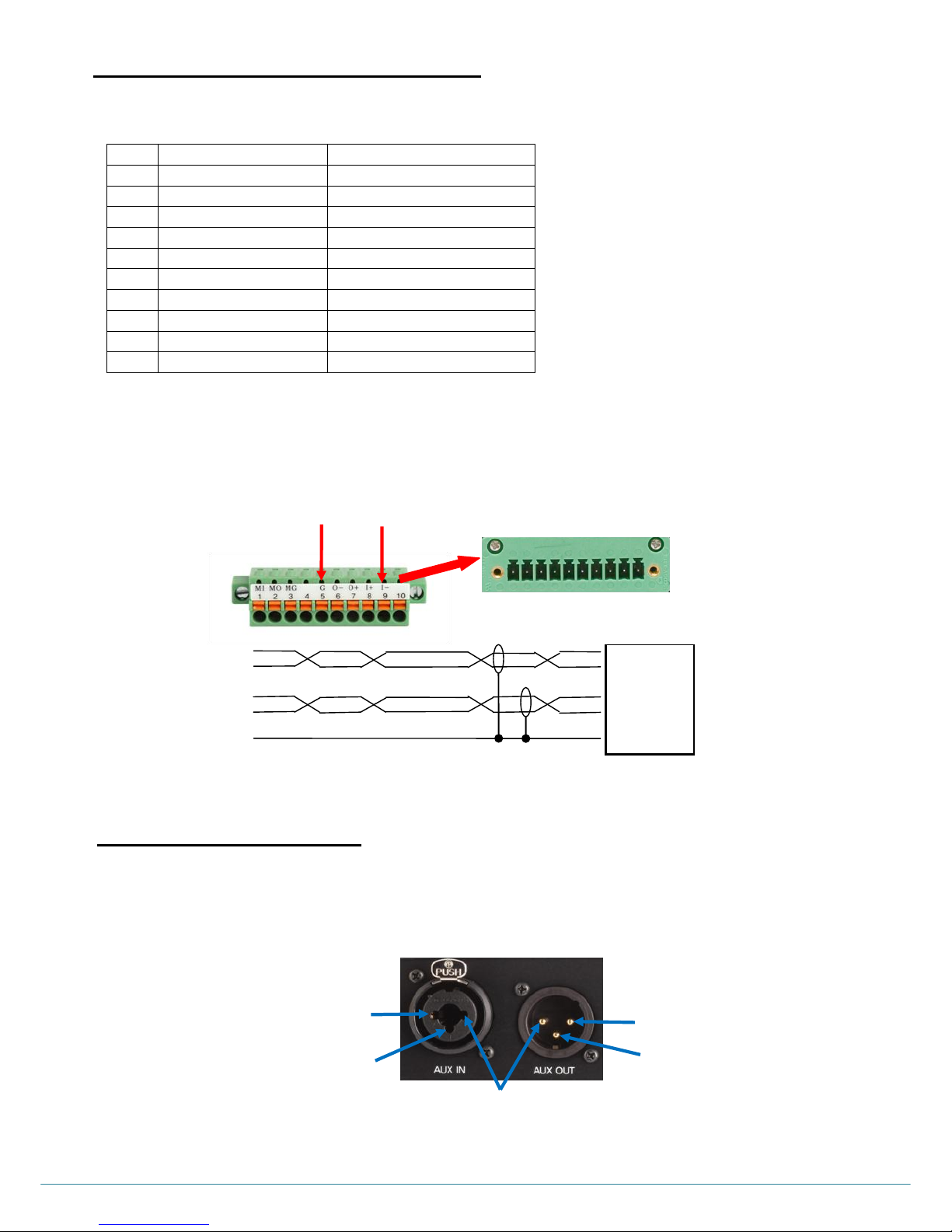
ⓒ2016 LaON Technology Co., Ltd. All rights reserved. 56
10 PIN SPRING CLAMP CONNECTOR
To plug a cable wire into the 10-pin spring clamp connector, push and hold an orange-colored wire-release latch on the top of the
connector, then put a cable wire into its relevant pin and release a wire-release latch.
Pin assignments for the „4-WIRE connector‟
4-Wire
AUXILIARY CONNECTOR
When you use auxiliary device such as intercom or other audio sources, put its output cable connector into the AUX IN connector
and its input cable connector into the AUX OUT connector. The AUX OUT and AUX IN connectors are 3-pin XLR type for balanced
+20dBV (10V) maximum level.
Pin
Function
descriptions
1
Input+ / Output+
2 Input- / Ouput-
3 NC(No Connection)
4 NC 5
GND
4-wire
6
4-wire output -
4-wire
7
4-wire output +
4-wire
8
4-wire input -
4-wire
9
4-wire input +
4-wire
10
NC
Pin 1
Pin 3
Pin 2
Pin 1
Pin 3
Pin 1 : Ground
Pin 2 : Audio +
Pin 3 : Audio –
4-Wire + ○9
IN - ○8
4-Wire + ○7
OUT - ○6
GND ○5
+ 4-Wire
- OUT
+ 4-Wire
- IN
GND
4-Wire device
„4-WIRE connector‟
Pin 9
Pin 5
10 pin spring clamp connector
Page 58
ⓒ2016 LaON Technology Co., Ltd. All rights reserved. 57
SECTION 8: TECHNICAL SPECFICATIONS
LT550 SYSTEM SPECIFICATIONS
BS550 BASE STATION
RF Frequency:
UNII band: 5.26GHz~5.32GHz, 5.50GHz~5.70GHz, 5.745GHz~5.805GHz
Antenna Connector Type:
External
1
/2
-wave dipole, SMA connector
Transmitter
Type:
Frequency/Time Diversity
Transmit Power:
17dBm(50mW) @antenna port
Modulation Type:
QPSK
Frequency Stability:
± 20ppm
Receiver
Type:
Antenna/Frequency/Time Diversity
RF Sensitivity:
-85dBm for 5 BER
Frequency Stability:
± 20ppm
Belt Packs per Base station:
Inherently, 128 Belt Packs can be paired up, and ten (10) Belt Packs
operating in full-duplex (talk/listen) at the same time while eleven (11) fullduplex channels are provided including the Base Station.
Audio Communication Group:
Five (5)
Audio Frequency Response:
200 Hz to 3.5 kHz with proprietary audio voice shaping
Audio Dynamic Range:
>70dB or more
Headset output:
50mW into 32 Ohm
Microphone Type:
Dynamic or Electret
Headset Connector:
6-pin mini-DIN male
Latency:
One-way system latency less than 23ms direct
Communication Security:
256 bits key AES level 3 Encryption
Auxiliary Input:
XLR-3F/
1
/4
”(6:35mm) combo jack, 600Ω balanced, level adjustable
Auxiliary output:
XLR-3M, 600Ω balanced, level adjustable
8Ω Speaker Output:
1W into 8Ω
4-Wire I/O:
10-Pin Spring Clamp connector, 600Ω balanced, level adjustable
LAN RJ-45 Connector:
One (STP standard wiring), Up to five (5) Remote Station can be connected
via LAN.
USB Connector :
Monitoring and Program port
Front Panel Display:
OLED 128 x 64 Resolutions
Front Panel Button:
Touch buttons
Power Input:
100-240VAC, 47-63Hz, 11.4-12.6VDC
Operating Temperature:
0°C to 50°C (32°F to 122°F)
Dimensions:
8.26W x 6.37L x 1.73H inch (21W x 16.2L x 4.4H cm),
Without Connector on the Rear panel and foot.
Weight:
2.4118 lbs (1094g)
Page 59

ⓒ2016 LaON Technology Co., Ltd. All rights reserved. 58
BP550 BELT PACK
RF Frequency:
UNII band: 5.26GHz~5.32GHz, 5.50GHz~5.70GHz, 5.745GHz~5.805GHz
Antenna Connector Type:
Internal
Transmitter
Type:
Antenna/Frequency/Time Diversity
Transmit Power:
17dBm(50mW) @antenna port
Modulation Type:
QPSK
Frequency Stability:
± 20ppm
Receiver
Type:
Antenna/Frequency/Time Diversity
RF Sensitivity:
-85dBm for 5 BER
Frequency Stability:
± 20ppm
Audio Communication Group:
Five (5)
Audio Frequency Response:
200 Hz to 3.5 kHz with proprietary audio voice shaping
Audio Dynamic Range:
>70dB or more
Headset output:
50mW into 32 Ohm
Microphone Type:
Dynamic or Electret
Headset Connector:
6-pin mini-DIN male
Latency:
One-way system latency less than 23ms direct
Communication Security:
256 bits key AES level 3 Encryption
Display:
OLED 128 x 32 Resolutions
Button:
Push buttons
Battery Requirement:
2.4V 2450mA h Rechargeable NiMH Battery or Two AA size 1.5V alkaline
batteries
Rechargeable Battery life:
Nine (9) hours in full duplex mode
Operating Temperature:
0°C to 50°C (32°F to 122°F)
Dimensions:
2.89W x 0.92L x 3.83H inch (7.35W x 2.35L x 9.73H cm) without Belt Clip
Weight:
0.445 lbs (202g) with battery / 0.29 lbs (133g) without battery
Page 60

ⓒ2016 LaON Technology Co., Ltd. All rights reserved. 59
RBS25 REMOTE STATION
RF Frequency:
UNII band: 5.26GHz~5.32GHz, 5.50GHz~5.70GHz, 5.745GHz~5.805GHz
Antenna Connector Type:
External
1
/2
-wave dipole, SMA connector
Transmitter
Type:
Frequency/Time Diversity
Transmit Power:
17dBm(50mW) @antenna port
Modulation Type:
QPSK
Frequency Stability:
± 20ppm
Receiver
Type:
Antenna/Frequency/Time Diversity
RF Sensitivity:
-85dBm for 5 BER
Frequency Stability:
± 20ppm
LAN RJ-45 Connector:
One (STP standard wiring) , Connect to the Base Station via LAN.
USB Connector :
Program Port
Power Input:
100-240VAC, 47-63Hz, 11.4-12.6VDC or PoE from the Network Switch
Operating Temperature:
0°C to 50°C (32°F to 122°F)
Dimensions:
3.46W x 1.47L x 4.80H inch (8.8W x 3.74L x 12.2H cm) without RBS holder
kit
Weight:
0.831 lbs (377g) without RBS holder kit
Page 61

ⓒ2016 LaON Technology Co., Ltd. All rights reserved. 60
THANK YOU!
 Loading...