

Lanzar VCAP8000 Owners Manual
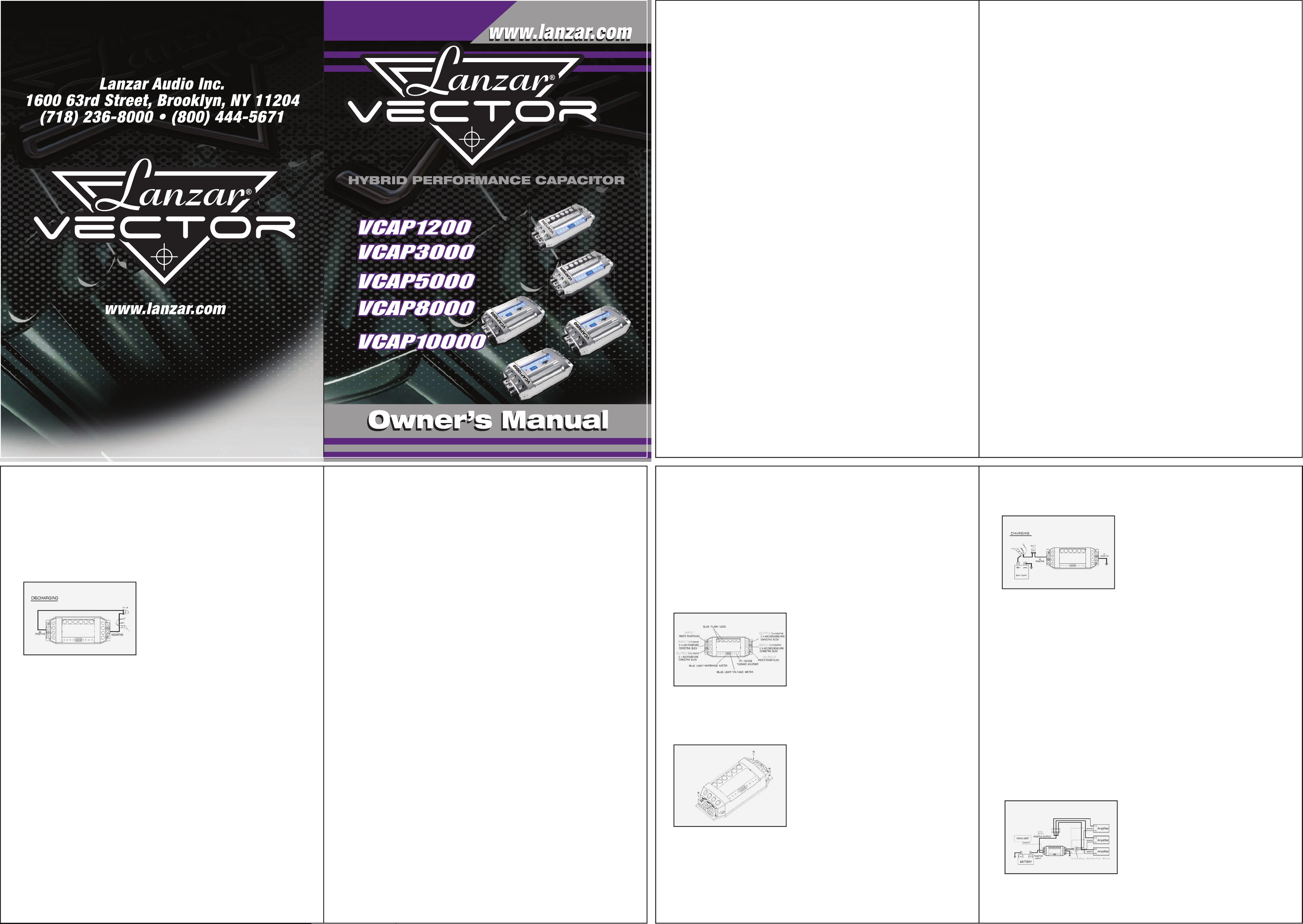
DISCHARGING THE CAPACITOR:
When you want to take out the capacitor after you finish the
installation process from original car audio system, you must do
discharge process when you want to move the capacitor. It will be
safe to release the power of the capacitor.
DISCHARGING
To discharge the capacitor: With battery power disconnected, place
the resistor across the capacitor’s positive and negative terminals,
after 1-5 minutes, the capacitor will be discharged. (The resistor will
become hot!) Then you can safely remove and handle it..
LIMITED WARRANTY
One Year Warranty from the date of purchase.
WARNING!!
THIS POWER CAPACITOR MAY EXPLODE AND CAUSE
SERIOUS INJURY IF ABUSED OR CONNECTED IMPROPERLY.
PLEASE REFER TO THE INSTRUCTIONS CONTAINED IN THIS
MANUAL FOR CORRECT MOUNTING,
CHARGING/DISCHARGING AND WIRING CONNECTION FOR
THIS CAPACITOR PRIOR TO INSTALLATION.
4
SPECIFICATIONS
Model: VCAP1200
12Farad Hybrid High Performance Capacitor
Capacitance……………………….….. 12,000,000 micro farad
Working Voltage……………………… 19DC
Surge Voltage…………………………. 24DC
E.S.R (Equivalent Series Resistance)… 0.0015 ohm @120hz/ 25℃
Capacitance Tolerance………………... ±10%
Model: VCAP3000
30Farad Hybrid High Performance Capacitor
Capacitance……………………….….. 30,000,000 micro farad
Working Voltage……………………… 19DC
Surge Voltage…………………………. 24DC
E.S.R (Equivalent Series Resistance)… 0.0015 ohm @120hz/ 25℃
Capacitance Tolerance………………... ±10%
Model: VCAP5000
50Farad Hybrid High Performance Capacitor
Capacitance……………………….….. 50,000,000 micro farad
Working Voltage……………………… 19DC
Surge Voltage…………………………. 24DC
E.S.R (Equivalent Series Resistance)… 0.0015 ohm @120hz/ 25℃
Capacitance Tolerance………………... ±10%
Model: VCAP8000
80Farad Hybrid High Performance Capacitor
Capacitance……………………….….. 80,000,000 micro farad
Working Voltage……………………… 19DC
Surge Voltage…………………………. 24DC
E.S.R (Equivalent Series Resistance)… 0.0015 ohm @120hz/ 25℃
Capacitance Tolerance………………... ±10%
Model: VCAP10000
100Farad Hybrid High Performance Capacitor
Capacitance……………………….….. 100,000,000 micro farad
Working Voltage……………………… 19DC
Surge Voltage…………………………. 24DC
E.S.R (Equivalent Series Resistance)… 0.0015 ohm @120hz/ 25℃
Capacitance Tolerance………………... ±10%
DETAILED FEATURES:
a) Chrome plastic case
b) Flashing Blue LED Lights
c) 4 digits blue light display DV voltage meter that can measure 0.1DCV range.
d) Reverse pole connection PCB buzz warning function. If the capacitor is
connected incorrectly by reversing the positive and negative wires during the
installation process the PCB will issue a noise to warn you.
e) Over voltage limit and low battery voltage limit warning, When the system voltage
peeks over 17.5DCV or LESS than 10DCV. The buzzer on the PCB will issue an
audible noise warning.
f) When the voltage between the positive and negative keeps same in two minutes,
the display will turn to sleep. When the voltage changes, display will wake and show
the voltage, LED will flicker.
CHARGING
To charge the capacitor:
1. Make Capacitor positive terminal connections with amplifier and
tighten the bolt. Do not over-tighten the bolts!
Caution: Stripped terminals are not covered under the capacitor’s
warranty.
2. Connect the ground cable with battery, amplifier, then refer to the
attached drawing.
3. Place the supplied charging resistor between positive terminal of
INSTALLATION AND MOUNTING:
Securely mount the capacitor using supplied hardware. Notice the small mounting
screw hole in the capacitor chassis.
the capacitor and the battery’s positive terminal. Do this for 2~3
minutes or until the charging resistor goes out.
Caution: The charging resistor will get hot!
4. Immediately take out the charging resistor from the connecting
wire after the charging process. And connect the positive cable of
the battery directly to the positive terminal on the capacitor.
CAPACITOR WIRING DIAGRAM:
CHARGING THE CAPACITOR AND WIRING:
The capacitor must be charged before connecting the Power and Ground cables to
the capacitor. Failure to charge the capacitor will result in a large spark generated
from the rapid inflow of current.
1
2
3
 Loading...