

Page 1

Page 2

INTRODUCTION
Congratulations on your purchase of LANZAR State of the art crossover. Your selection of a
LANZAR car audio product indicates a true appreciation of fine musical reproduction. Whether
adding to an existing system or including your LANZAR crossover in a new system, you are
certain to notice im medi ate performance benefits .
KEEP YOUR SALES RECEIPT
Take the time to attach your sale receipt to the manual and put it in a safe place. In case of any
unforeseen reason this product may need warranty service, your receipt will be necessary to
establish the purchase date.
RECOMMENDATION
Crossover performance is only as good as its installation. Proper installation will maximize the
system’s overall performance. It is recommended that you have our product installation by an
authorized LANZAR dealer. However, if you decide to install it yourself, please carefully read
through this manual and take your time to do a quality installation.
IMPORTANT!
Before making any connection, disconnect the car’s battery until the installation is
completed to avoid possible damage to the electrical system.
WARNING!
Exposure to high power sound systems can c ause hea ring l oss or dama ge. Li stening
to your system at loud levels while driving will impair you日 ability to hear traffic
sounds and emergency vehicles. Use common sense when listening to your system.
Systems is plural you have it singular
1
Page 3
SYSTEM LAYO UT
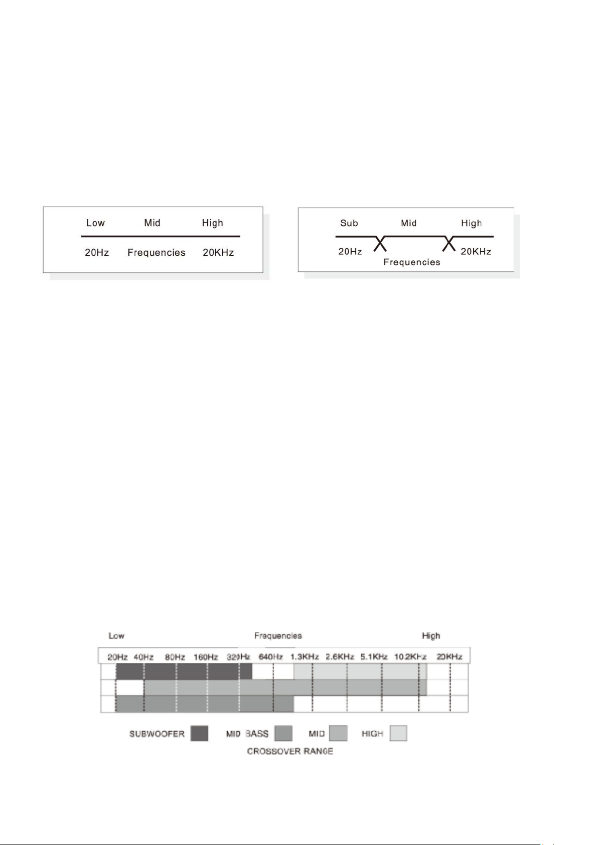
The primary function of the crossover is to filter the audio signal. Basically, the OPTIXA6B
divides the audio signal into six separate parts….Subwoofer, Mid Bass, Band Pass 3, Band
Pass 2, Band Pass 1 and high.(See Figure #1).Although the OPTIXA6B has rather simple
connections, it is important for you to have a general understanding of the operating range of
your system to properly setup the system as well as to make the final adjustments.
Full Range Output Six-way Output
(FIGURE#1)
FULL RANGE VS.THREE-WAY OUTPUT
In order to reproduce the music in which it was recorded, your audio system should have the
ability to recrea te all au dio i nfor mation from 20 Hz up to 20KHz (T his i s know n as hu man audi ble
range).One of the most important factors in sound quality is the over all balance of the
frequency reponse ,bett er k now n as the li near it y of th e sound. In a perfectly balance sys tem, the
low to high frequencies are reproduced without missing information. Unfortunately there are
many factors that can cause loss of frequencies in your system. Some loss may be caused due
your speaker’s frequency response, crossover points, and level adjustment.
Before you set up the system it is best to first layout your system maintaining the speakers
operating range. The following graph will give a general idea the Subwoofer, Mid Bass, Mid
range and High operating range for the OPTIXA6B crossovers.
(FIGURE # 2)
OPTIXA6B CROSSOVER AND OPERATING RANGE
2
Page 4

SAFETY PRECAUTIONS
Fuse crossover’s power wire at the battery
Be sure to fuse (1 amp) the power wire within 12’’ of the car’s battery. This will protect the car’s
battery in case of a short circuit between the crossover and the battery. THIS IS A MUST.
Use high grade wire connectors
To ensure maximum power transfer and secure safe connections, it is recommended to use
high grade barrier spades (for connections at crossover) and terminal rings (for connection at
battery).
Do not run any wires undernea t h vehicle
Exposed wires have a chance of being cut or damaged. It is best to run all wires through the
vehicle under th e carpet and / or si de panels. Thi s l ends to a cleaner i nstallation and les s r i s k o f
damage.
Use caution when mounting the cr ossover
Remember t hat there are many electrical wires , gas lines , vacuum lines , brake lines as well
as a gas tank in the automobile .Make sure you know where they are when mounting the
crossover to avoid puncturing lines , shorting wires or drilling holes in the gas tank.
Run signal wires away from electrical w ire s
To avoid possibility of induced noise from the car’s electrical system (i.e.popping noises or
engine noise), run signal wires away from the car’s electrical wiring.
Make all ground wires as short as possi ble and at the same point
In order to reduce the chance of ground loops (i.e. engine noise), make the grounding wire as
short as possible to reduce the wire’s resistance .Also, when using multiple components, make
sure all units are ground at the same point.
Avoid sharp edges w he n running the wires
To avoid the possibility of pow er, signal or speaker short s b e care ful not to al low the cr osso ver’s
wires to come in contact with sharp edges .Use a grommet to protect the wire when running
through the firewall.
3
Page 5
MOUNTING LOCATION
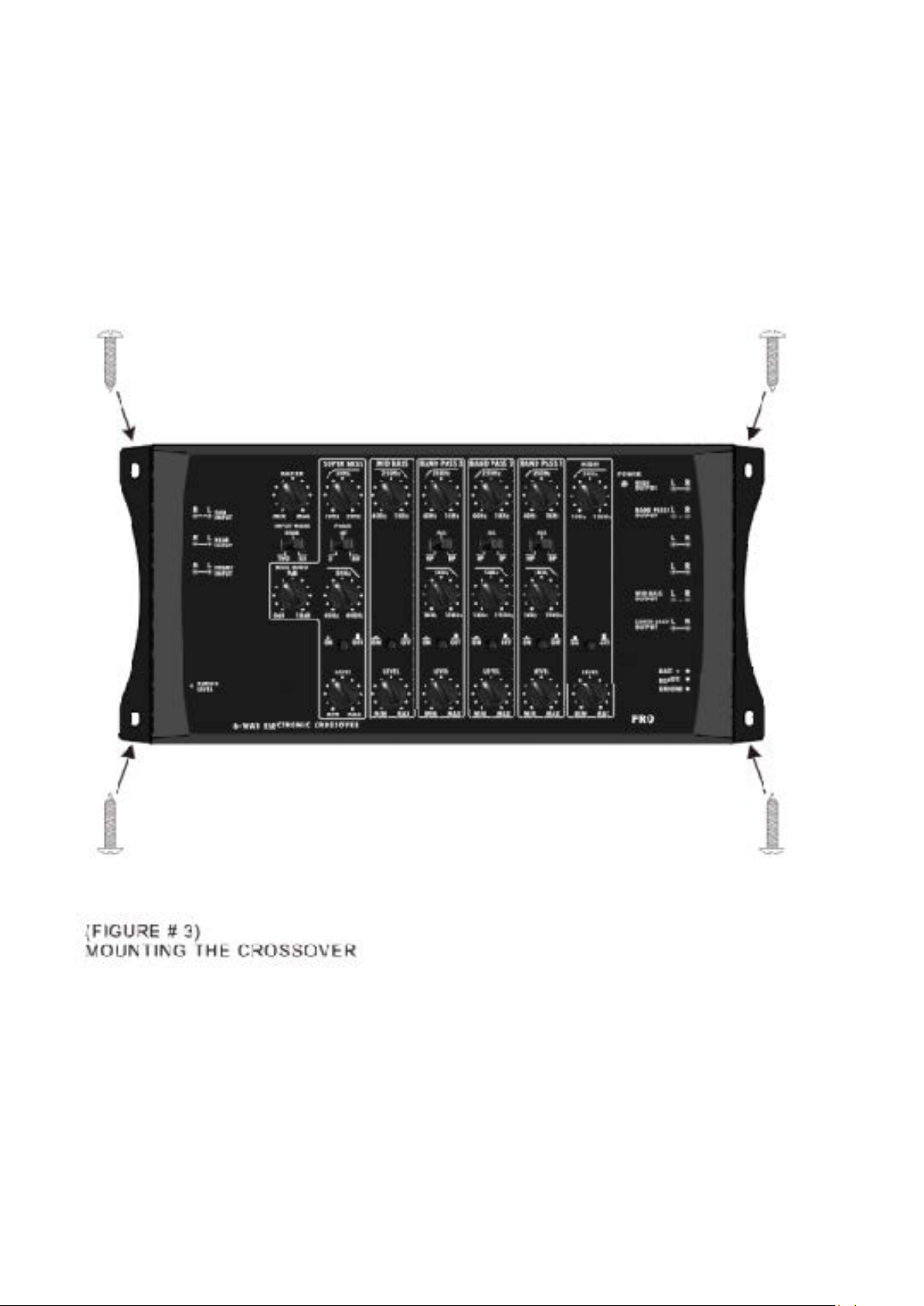
Select the location in which you wish to mount the crossover , It is recommended to find a
location that will allow easy adjustment .Use caution when mounting crossover …there are
many wires ,gas lines, vacuum lines brake lines as well as a gas tank in the automobile .Make
sure you know where they are when mounting the crossover to avoid puncturing lines ,shorting
wires or drilling holes in the gas tank .Once you are ready use a pencil to mark the through
holes in the bottom p a nel .After you have mar k ed the l ocations of the holes move crossover out
of the way and drill small starter holes to make the taping screws easier to install .Use provided
screws to tighten down the crossover (see Figure #3).
4
Page 6

IMPORTANT!
Before making any connection, disconnect the car’s battery until the installation is
completed to avoid possible damage to the electrical system.
Connect the Power terminal of the crossover to the car’s *battery.
Use a 16 gauge wire to connect to the terminal on the crossover marked + 12V. Run the wire
directly to the positive terminal of the car’s *battery. Make sure to use an in-line fuse (1 amp)
within 12’’ of the battery.*Since the crossover’s current draw is nominal, you can connect to the
pre-existing +12V power wire that has been run for the crossovers if so desired.
Connect the ground terminal of the crossover to the car’s chassis
Use a 16 gauge wire to connect the GROUND terminal to the car’s chassis .Try to keep the
length of the cable as shor t as p os si bl e , pr e ferably less than 12’’, Also make sure that t he poi nt
on the car chassis where the connection is to be made is free of paint and dirt .It is
recommended to grounding point as the amplifiers to eliminate the possibility of ground loop
(engine noise )caused by different levels of ground to each of the components .
Connect the remote terminal of the crossover to a switchable +12V
This connection allows the crossover to be turned on and off with the power control of the head
unit .If the head unit has a PEMOTE OUTPUT WIRE (+12V), connect it to the OPTIXA6B
terminal marked REM .Now when the head unit is turned on, the crossover will automatically
turn on, If the head unit does not provide a remote output, it is necessary to connect the
crossover to switched +12V power supply (when the car is on or in use).
5
Page 7

SIGNAL CONNECTIONS
Before making your signal connections, you will need to decide how you wish to configure your
system .The OPTIXA6B is extremely flexible allowing for many different configurations .All
signal connections should be made using higher-grade RCA patch cables and these cables
should be run away from electrical wiring to avoid inducted noise . The OPTIXA6B allows for
three different types of input connections that control all three outputs of the crossover.
1) USING ONE PAIR OF PRIMARY INPUTS
When only one pair of input is available ,use the “1/2” input section and set the INPUTS switch
to “TWO” .This will allow the signals to be fed internally to the SUBWOOFER and REAR
sections to give proper outputs .You have Subwoofer Amplifier twice in the bottom design.
6
Page 8

2) USING TWO PAIRS OF INPUTS
When front a nd rea r pairs of i nput a re available, from the source, use the“1/2” and “3/4” inputs,
respectively. Set the INPUTS switch to “FOUR” position to allow the signals to be fed internally
to the SUBWOOFER section to give proper outputs to allow control of fader from the head unit.
3) USING THREE PAIRS OF I NPUTS
All three pairs of inputs on OPTIXA6B can be utilized when front, rear and subwoofer pairs of
inputs are available from a pre-amp EQ. Set the SUBWOOFER INPUT switch to” DIRECT”
position to allow independent subwoofer level control from the EQ to allow control of fader from
the head unit. Note that some head units offer independent subwoofer output signals as well.
7
Page 9

1) SETTING THE SUBWOOFER CROSSOVER POINT, PHASE,& SUBSONIC FILTER
Set the desired CROSSOVER FREQUENCY for the subwoofer output using the LOW PASS
FREQUENCY dial. You may select from 40Hz up to 400Hz as your crossover point.
Select the PHASE of the subwoofer using the PHASE switch,0 degrees in phase or 180
degrees out of phase.The normal default setting is 0 degreed in phase.
SUBSONIC FILTER with a variable Full/30Hz/50Hz subsonic filter. This filter avoids the
reproduction of inaudible low frequencies on the amplifier which could damage the subwoofer
because they can generate over excursion of the subwoofer cone.You would want to set the
frequency point where you want the filter not to produce frequencies below that
point.Generally,human ears cannot hear low freqencies below 20Hz.
8
Page 10

2) SETTING THE CROSSOVER POINTS FOR THE REAR (MIDRANGE) OUTPUT
Usually the MID output is a BAND PASS design. It ’s achieved by setting the MODE switch at
“BP” and using both HIGH PA SS and LOW PASS FREQUENCY dials. Set the desired HIGH
PASS frequency anywhere between 40Hz and 1KHz for the low frequency cutoff, and set the
desired LOW PASS frequency anywhere between 1KHz and 12KHz for the high frequency
cutoff.
Selecting HIGH PASS from the MODE switch and using HIGH PASS FREQUENCY dial alone
will remove the high cut off section and allow the midrange output to play up to 20KHz.
Selecting ALL from the MODE switch. This setting will be ideal if you’re using ALL range
speakers capable of reproducing Full frequencies.
3) SETTING THE CROSSOVER POINT FOR THE FRONT (HIGH) OUTPUT
Set the desired frequency cutoff point using the HIGH PASS FREQUENCY dial for your HIGH
output such as Tweeters and/or Compression Drivers. The frequency range for this pair of
channels is 1KHz to 12KHz.
9
Page 11

FINE TUNE THE SYSTEM
One very impor t ant part of fin e tuning your sys tem i s pr oper l y level matching the signal from th e
head unit to the OPTIXA6B crossover and from the crossover to the amplifiers. Level matching
is the process of calibrating the audio signal from the head unit all the way to the amplifiers to
eliminate unwanted noise and maximize the dynamic headroom. When the system is properly
adjusted, you should achieve maximum output before distortion at about 3/4 volume on the
head unit.
MATCHING THE SIGNAL LEVEL
1) Turn all amplifiers to min-gain
2) Turn all six channels off via the push button switches.
3) Turn all six level controls to their “max” setting.Yes,”max” as these are attenuators and not
gain or boost potentiometers.
4) Turn the “master” gain control to its minimum setting. This is the main control of the 15-volts
line driver. Use it carefully.
5) Set the head-unit or radio to approximately 3/4 volume.
6) Begin by selecting a channel by turning it “on” and begin raising the amplifier gain until you
reach a desired level of volume.
7) Follow this procedure for all channels that will be used.
8) Raise the “master gain” as desired but try to never pass the 10 O’clock position.
Once all adjustment are made, the system should sound clear without distortion up to 3/4 of
main volume. Also the volume should increase very evenly.
ADJUSTING THE OVERRALL BALANCE OF THE SYSTEM
Once you complete matching the signal level, the following steps ought to be made to set the
overall linearity of the system. This may be necessary due to the relative efficiencies of each of
the speakers. For example, smaller speakers normally are more efficient then woofers and play
louder faster at given equal power (See Figure # 4)The OPTIXA6B’s individual output level
controls allow compensation for this.
It is important to understand that the output levels are not designed to add gain to the
signal.Actually,the output level controls attenuate(reduce signal gain).It is for this reason that in
the following steps we will start with the output levels at the maximum position then reduce the
outputs to ba lance the system. For example, if you like heavy bass, you will most likely leave
the SUBWOOFER OUTPUT LEVEL at the maximum position and reduce the MID and HIGH
speakers. If you wish to increase the MID and HIGH frequencies, reduce the SUBW OOFER
OUTPUT LEVEL.
(FIGURE # 4)
A VISUAL EXAMPLE OF DIFFERENT OUTPUT LEVELS BASED ON THE SAME POWER
INOUT
10
Page 12

TROUBLE SHOOTING THE SYSTEM
We have put together this trouble-shooting guide if you experience problems after installing the
crossover. Please keep in mind that the majority of problems incurred are caused by improper
installation and not the equipment itself. In addition, there are many components in the system
that could cause various signal problems such as inducted electrical noise and engine noise.
Problem… SOLUTION
No Output
Blown fuse Replace
Bad RCA Cable(s) Replace
+12V at power terminal Check connection
+12V at remote terminal Check connection
Grounding point clean and tight Check for ground w/mater
Head Unit’s fader not in center position Set to center position
Low Output
Check level adjustments Re-adjust
Bad RCA cable(s) Replace
Improper level matching
Engine Noise
Grounding points are clean and tight Check for ground w/meter
Ground all components at same point Ground at same point
Try different grounding point Charge for better ground
Bad RCA cable(s) Replace
USE High Quality shielded RCA cable Rejects include noise
Low Vehicle charging system and /or battery Fix and/or repla ce
11
Page 13

SPECIFICATIONS
GENERAL
Total Harmonic Distortion @ 1KHz………………………………………………………0.04%
Signal to Noise Ratio…………………………………………………………………….>105dB
Stereo Separation…………………………………………………………………..……...>70dB
Current Drain………………………………………………………………………….……200mA
Remote Turn-on Time………………………………………………………………….….0.5sec
Recommended Fuse……………………………………………………………………..........1A
Dimensions.................…………………………………………………….1.6”Hx5.9”Lx12.8”W
INPUTS
Input Impedance
Front & Rear & Subwoofer…………………………………………………….….22K-Ohm
Input Voltage………………………………………………………….………….150mV~1.6V
OUTPUTS
Crossover Cut Off Slope…………………………………………………………..12dB/Octave
Maximum Output Voltage…………………………………………………………………….15V
SUBWOOFER
Low Pass Crossover Frequency………………………………………….40~400Hz
Subsonic Filter……………………………………..………………….Full/30Hz/50Hz
Phase Shift……………………………………………………….……………..0 or 1800
Bass Level Remote Control…………………………………………………….Wired
Rear (Mid Bass/Band Bass 3):
Mid Bass: Low Pass Crossover Frequency…………………………40Hz ~ 1KHz
Band Bass 3:
High Pass Crossover Frequency……………………………………..40Hz ~ 1KHz
Low Pass Crossover Frequency…………………………………….. 1KHz~12KHz
Front(HIGH/Band Pass 1/ Ba nd Ba s s 2):
High:
High Pass Crossover Frequency…………………………………..…1KHz~12KHz
Band Bass 1 & Band Bass 2:
High Pass Crossover Frequency……………………………………..40Hz ~ 1KHz
Low Pass Crossover Frequency…………………………………….. 1KHz~12KHz
12
Page 14

 Loading...