

Page 1
DIGITAL
ENHANCER
BASS
Page 2

INTRODUCTION...
Congratulations on purchasing the LANZAR OptiX-9. You are now the proud owner of
the finest and most accurate bass enhancing & restoration system available.
Whether your interest is in Beethoven's kettle drums, in Miles Davis' trumpet or in the
percussion of Rap lyrics, the OptiX-9 would restore those long lost missing bass
notes, with amazing accuracy and clarity.
There's a dash mounted level control unit which permits instant adjustments; whether
it's because your passenger is not as much a "bass-head" as you are or for whatever
reason you want to turn it down a bit, this handy knob does the trick.
Before you start to install this audio product to your music system, please take a few
minutes to sit back and read through this manual. It contains lots of useful facts and
information.
FEATURES
Bass Driver: The OptiX-9 contains a Bass Driver circuit that accurately recreates
and injects Low frequency information back into the signal path. What that means in
everyday terms is that the OptiX-9 will give more bass impact to your best compact
discs or even your old tapes.
Bass Equalization Circuit: The OptiX-9 has a unique equalization circuit that contours
the restored bass to your speaker systems.
Dash Mount Control: The OptiX-9 comes with a dash mountable control that allows you
to enjoy the effects of the OptiX-9 without having to leave the drivers seat. The dash
mount control has a LED indicator, this LED will grow brighter as you add more bass or
dimmer when you decrease it.
Bass Maximizer Indicator: Not only does The OptiX-9 provide good music to your ears,
but it also gives you some visual enjoyment as well. On the Chassis of the OptiX-9, there
are two LED indicators that flashes when the bass maximization circuit is activated.
PFM Subsonic Filter Control: This unique feature is legendary with its ability to fine tune
the bass response of any system. Why waste power on nasty subsonic information when
PFM Subsonic Filter Control can help you to clean things up?
Bass Output Control: The OptiX-9 has the ability to produce large amount of deep,
mind shattering bass without damaging your speakers. The Bass Output Control circuit
allows the OptiX-9 to maximize the bass output of any autosound audio system while
restraining destructive bursts.
- 1 -
Page 3
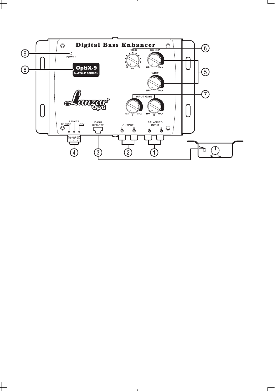
FUNCTIONS
THE OUTSIDE
1. Inputs: The inputs of The OptiX-9 use a balanced input circuit to help minimize induced
noise. They are also designed to handle very high signal voltages up to 15 volts.
2. Outputs: These RCA connectors should be connected to the next component after the
OptiX-9, such as a crossover, equalizer, or amplifier. Just remember, the OptiX-9 should
go inline before a crossover.
3. Dash Remote Control
4. Power Connector
5. Para-Bass Controls: These 2 knobs control the Para-Bass functions of the OptiX-9.
The SWEEP knob allows you to pick the center frequency that you want the OptiX-9 bass
restoration circuit to maximize. The WIDE knob adjusts how wide of a frequency range the
OptiX-9 will effect.
6. The PFM Subsonic Filter Control: The OptiX-9 utilizers a PFM Subsonic Filter Control
which will help with speaker control and amplifier power management. This PFM Subsonic
Filter Control comes with frequencies selections from 32Hz to 250Hz. On most systems,
setting the switch at 32Hz is fine. If you want to protect your speaker system even more, you
should try a higher frequency. Often a higher frequency actually sounds louder and cleaner.
7. Input Gain Controls: Input signal L/R can be adjusted with these control. Turn the knob
clockwise to increase the input level or turn counterclockwise to reduce the input level.
8. Bass Maximize Indicator Display: This lens display with light up effect which flashes when
the bass maximization circuit is activated.
9. Power On LED.
- 2 -
Page 4

10. Input Grounding: For most systems you can leave this jumper set in the BALANCED
position. In some systems, the source unit may look for a ground through the RCA
connectors. In this event, you should go ahead and change the jumpers to the
UNBALANCED position.
11. Ground Isolation Jumpers: Occasionally alternator whine may appear in a
system because the source unit and amplifier may use different grounding. To help
in this situation, we have provided alternative grounding connections. Made sure
your system is turned OFF before you move these jumpers.
12. Bass Output Control Jumpers: Not all systems are designed the same, some
systems are designed strictly for SPL (sound pressure level) while others are a little
more tame. The Bass Maximize circuit can either increase or decrease the signal
voltage of the Bass Restoration Circuit. Depending upon your system, you may opt to
change these jumpers to a higher or lower setting to maximize your bass output and
protect your speakers. In most systems the factory setting will suit you fine. We
recommend you try the factory setting first.
- 3 -
Page 5

Power connection
B+(12V) : Connect a red wire to the car battery or other power source.
REMOTE: Connect an orange wire to remote activating (12V DC)wire of car
stereo or equalizer.
GND : Connect a black wire to the car chassis for ground connection.
- 4 -
Page 6

SIGNAL
Head
Unit
CONNECTION
Equalizer
0
Digital
0
0
!'OWER
Bass
Enhancer
.REQ
!Si
0
'WEE~
~
Ell
9
dlmffBt
0 0
= =
o 0
..
S)'S)
0
NOTE:
For
to
the
next
amplifier.
Just
o o
Crossover
signal
connection,
component
remember,
after
= =
the
output
RCA
the
the
OptiX-9
OptiX-9,
such
should
SUBWOOFSHIONO
f.i ",,··",·1-\-1,
connectors
as a crossover,
go
inline
- 5 -
should
before a crossover.
CIIMNELAr.t'l.FER
be
connected
equalizer,
or
,,"'
"
SUIIWOOFER
Page 7

Adjusting the Para-Bass Controls
The bass response in a system is affected by four factors:
(1) The acoustics of the vehicle
(2) The locations of the speakers
(3) The music on the tape
(4) Speakers and speaker enclosures.
Because of the variations in the recording process, we developed OptiX-9 to help
restore any low frequencies lost during the recording process, however, the acoustics
of various environments are different.
The Sweep control allows you to select a center frequency (the frequency most
affected) between 27 and 63 Hz. The Width control then allows you to control the shape
of the filter centered around the Sweep frequency.
Setting The Bass Output Control
The Optix-9 is the most powerful bass component. This device equipped with several
different Bass Output selections. If you should need to change the settings, Please use
the chart below for guidance. It is recommended:listen to the factory setting before
changing your Bass Output settings.
Recommended Settings
Setting Amplifier Input Voltage Minimum Speaker Size
2.5Volt 3Volt or less 8"
5Volt 5 Volt or less 10"
7.5Volt 7.5 Volt or less 12"
10Volt Oh My Gosh !!!!!!!!!!!!!!!!!
SPECIFICATIONS
Maximum Input Level .................................................................15V RMS
Maximum Output Level ..........................................................13.5V peak
Frequency Response ...........................................10Hz- 100KHz ; +/-1dB
Total Harmonic Distortion ............................................................0.003%
Signal to Noise Ratio ...................................................................-130dB
Balanced Input Noise Rejection .................................................... >60dB
Input Impedance ....................................................................10 K Ohms
Output Impedance ...................................................................150 Ohms
Power Supply .........................................................High headroom PWM
Power Draw .................................................................................150mA
Recommend Fuse Rating ...............................................................1 Amp
- 6 -
Page 8

TROUBLE SHOOTING GUIDE
If the Unit does not turn-on, and /or the power indicator LED is NOT
illuminated, do this :
1) Check and make sure that B+ and GND are not reversed
2) Check that all power wires are properly connected and has
the appropriate potential (11-16 volts)
3) Check that the fuse is intact.
If you experience high audible distortion or low output volume :
4) Check that the input and output levels are set correctly. Input should
match the source and output should match the sensitivity of the host.
5) Check the crossover settings;make sure they are correct; for high "Q"
systems, set the crossover half an octave above the desired point and for
low "Q" systems, set it 1 octave or more above.
If you experience whining or engine noises :
6) Verify that the GND connection is secure, the conductor (wire) is not too
thin and unnecessarily long.
7) Check that the B+ wire is not too thin and unnecessarily long.
8) Change the power source;try taking power from a different point.
INSTALLATION
 Loading...