

Page 1
user’s manual
www.lanzar.com
OptiD-100
OptiD-100
High Performance 7 Volt Line Driver
Crossover Network w/Remote Bass
Boost , Level and Q Controls
Page 2

INTRODUCTION...
Congratulations on your purchase of a new Lanzar Opti signal processor. Opti mobile electronics are some of the most advanced
car audio products available. These quality audio products are designed and engineered to afford you years of uncompromising
musical service. Lanzar has utilized the latest electronic technologies in order to deliver a superb listening experience.
The D-100 Active Line Driver offers the listener the ability to enjoy the finest in mobile audio. The D-100 unleashes the effortless,
natural and open quality of the real performance. Car audio systems which utilize passive crossovers feed the music through
chokes and capacitors, which creates a “bottleneck” through which the music must pass. Portions of the program material may
pass through at different speeds, creating distortion – some of the music doesn’t make it through at all!
With the Lanzar Opti D-100 you’ll hear all the dynamics in the bass, and still hear delicacies like fingers sliding across guitar
strings.
Page 3

table of contents
general features
precautions
features and specifications
system wiring
mounting and installation
noise check and system adjustment
troubleshooting
2
3
4-5
6
7
8
9
Page 4

general features
Blue light illuminated control panel
Rotary control knobs
PWM power supply
Variable line out level control
Variable input level control
Subwoofer variable phase shift control
Subwoofer stereo/mono mode control
Remote bass boost , level and Q controls
Variable bass boost frequency : 40-400 Hz
Variable Q (2-20)
2
Page 5

Precautions
To prevent short circuits, be sure to disconnect the negative battery ground lead before wiring the system up.
When you finish the installation, be sure to make one more check to be sure everything is done correctly.
Reinstate all car parts that were removed.
Reconnect the negative battery ground lead.
3
Page 6
features and specifications
4
Page 7

features and specifications
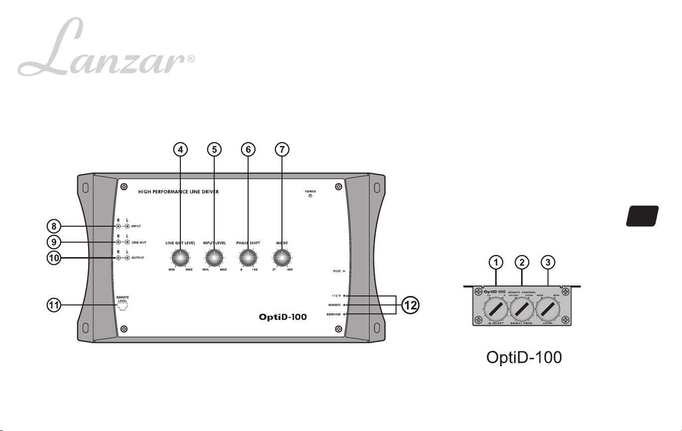
1. PARAMETER "Q" SELECT 2-20
2. BASS BOOST FREQUENCY CONTROL
3. BASS BOOST LEVEL CONTROL
4. VARIABLE LINE OUTPUT LEVEL
CONTROL
5. VARIABLE INPUT LEVEL CONTROL
6. VARIABLE SUBWOOFER PHASE SHIFT
CONTROL 0-180
7. SUBWOOFER STEREO/MONO MODE
CONTROL
8.INPUT PORT
9.LINE OUT PORT
10.OUTPUT PORT
11.REMOTE CONTROL JACK
12.POWER TERMINALS
Allows independent continuous change of the boost frequency bandwidth (Q-factor) for
each band from Q=20 (Narrow bandwidth, steep slope) to Q=2 (Wide bandwidth, gentle
slope).
This control adjusts the bass boost frequency from 40Hz to 400Hz.
This control sets the subwoofer gain control.
Turning this control to adjust the output sensitivity of line out to match the input of additional
amplifier, crossover or audio system.
Turning this control to adjust the input sensitivity of the set to match the radio's output.
Allows you to control the phase of your subwoofer between 0 degrees and 180 degrees to
help compensate for timing difference between drivers.
Allows you to control the subwoofer output between stereo and mono, thus facilitating single
subwoofer installation.
To be connected to the outputs of the source unit or signal processor.
To input additional amplifiers, crossover or Audio system.
To be connected to the amplifier left/right inputs.
Plug the modular telephone style cord connected to the remote control unit into this jack.
Use these connectors to deliver power, ground, and remote turn-on control to the unit.
Adjustable Bass Boost
Frequency
Adjustable Bass Boost
Adjustable Q Control
Power Supply
Input Impedance
S/N ratio
Max Output Signal Level
Channel Separation
Distortion
Dimensions,WxDxH,inches
(millimeters)
REMOTE CONTROL UNIT
1.Q SELECT
This control will narrow or widen the boost frequency bandwidth (Q=factor) being
sent to the amplifier for each band from Q=20 (Narrow bandwidth, steep slope) to
Q=2 (Wide bandwidth, gentle slopes).
2.BASS FREQUENCY
This control sets the center frequency of the bass boost effect from 40Hz to 400Hz.
40Hz-400Hz
0-18dB
2-20
10-16V DC, negative ground
10K Ohm
more than 85dB
7.0V RMS
60dB
less than 0.05%
6x10-11/16x1-3/4
(150 x 272 x 45)
5
3.BASS LEVEL
This control sets the subwoofer level control.
Page 8
System wiring
6
Page 9
Mounting and installation
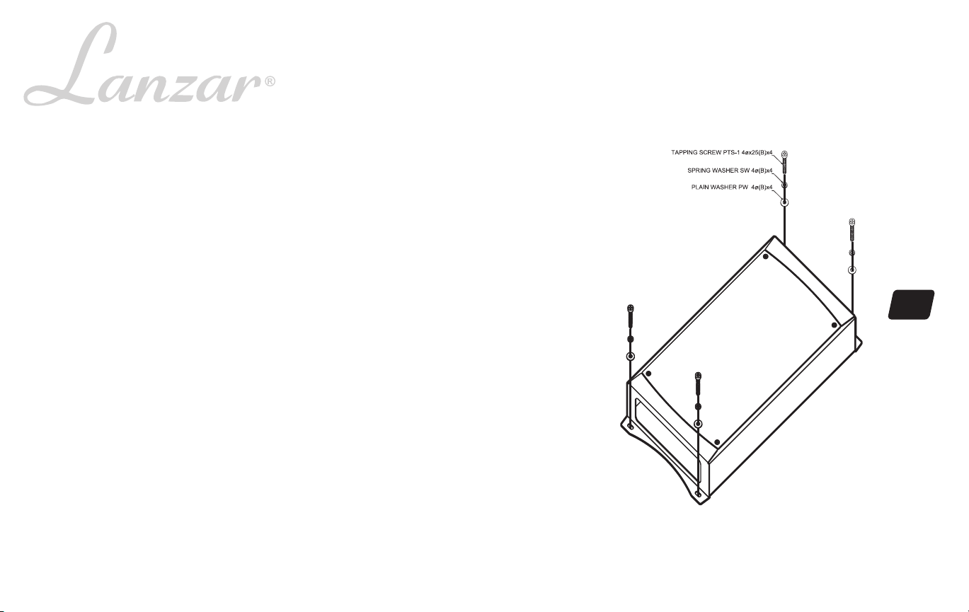
Your new Opti Series Line Driver comes complete with all required mounting hardware.
Mark the location for the mounting screw holes by positioning the Line Driver where you wish to install it
and use a scribe (or one of the mounting screws) inserted in each of the mounting holes to mark the
mounting surface. If the mounting surface is carpeted, measure the hole centers and mark with a felt tip
pen.
Before attempting to drill the mounting holes, take note of any wires, lines or other devices in your vehicle
which may be located behind the mounting surface! Then drill pilot in the mounting surface for the mounting
screws and insert then. Tighten the screws securely.
Installation
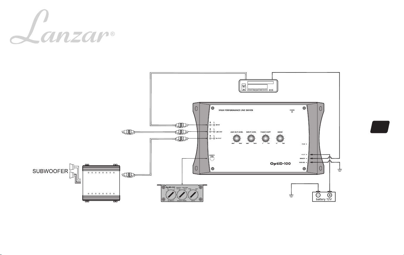
• A red 18 gauge stranded or heavier and insulated wire should be connected to the terminal marked +12V.
Wire an in-line fuse holder on this lead as it is the 12 Volts DC wire for the system. This wire should be
connected to your vehicle’s battery. If a wire is run directly to the battery make sure to install an in-line fuse
on this wire within 12” from the battery.
• A black stranded wire of at least 18 gauge should be connected to the terminal marked Ground. This is the
ground wire for the D-100 and should be attached to the same ground point with the amplifiers in the system.
Keeping this ground wire as short as possible improves the electrical circuit and keeps ground related noise
problems to a minimum.
• An orange stranded wire of a least 20 gauge should be connected to the terminal marked Remote. This wire
connects to your head unit’s remote out or power antenna lead out. This wire should supply 12 Volts DC any
time the radio, cd or cassette are playing. This lead must also be connected to any other components in your
system that utilize a remote turn-on lead for powering up.
• Connect all line inputs and outputs using high-quality RCA-RCA cables.
• Recheck all connections before powering up.
• Set all level controls to their least sensitive positions and set all Line Driver controls, switches, etc. to the
desired frequency or position.
• Once the system is powered up, set the volume control on the head unit to about the 2 o'clock position, and
then set all the amplifiers' level controls for half output level.
7
Page 10

Noise check and system adjustment
NOISE CHECK
Check the entire audio system for noise before permanently securing the Line Driver mounting
1. Start the engine.
2. Turn the audio system on.
3. Rev the engine and vary the VOLUME of the audio system to determine if there is any unwanted noise.
If so, turn both the audio system and the engine off. Do not secure the Line Driver mounting screws. Refer to the "Trouble Shooting Guide" at this manual.
4. If the audio system does not have any noise, securely tighten the Line Driver mounting screw and double check the wiring cabl
SYSTEM ADJUSTMENT
Preliminary Adjustments
Pre-setting the system provides a necessary starting point for fine-tuning the entire audio system to maximum performance.
NOTE: DO NOT MOUNT Line Driver UNTIL THE FOLLOWING PROCEDURES HAVE BEEN COMPLETED.
1. Preset each amplifier input gain adjustment at the amplifier to half of maximum.
2. Slowly turn the volume up and listen carefully for: obvious trouble in sound (distortion, no sound, no hiss, total silence). Turn the system off refer to "Trouble Shooting
Guide" at this manual.
Caution
DO NOT ROUTE AUDIO CABLES AND POWER CABLES TOGETHER! THIS CAN CAUSE ENGINE NOISE IN YOUR AUDIO SYSTEM. ALWAYS DISCONNECT
THE SYSTEM FROM THE BATTERY BEFORE ATTEMPTING TO MAKE OR ALTER ANY CONNECTIONS. THIS PRODUCT IS DESIRED FOR USE IN ANY
12 VOLTS NEGATIVE GROUND ELECTRICAL SYSTEM ONLY. INSTALLING THIS PRODUCT IN ANY POSITIVE GROUND ELECTRICAL SYSTEM COULD
SERIOUSLY DAMAGE THE AUDIO SYSTEM.
Adjusting The Line Driver
The Line Driver provides variable enhancement of Line frequencies. The level of peak boost varies from 0 to +18dB and the frequency at which peak boost occurs is adjustable
from 40Hz to 400Hz. 20-Q to 2-Q boost characteristic can be adjustable.
2-Q characteristic boosts a wide range of frequencies and is useful for general sound quality enhancement. The 20-Q characteristic boosts a narrow range of frequencies
and can be used to tune a subwoofer system fo rmaximum output.
The Line Driver Q adjustable should be set to the 2-Q(wide) position and the frequency control set approximately one octave below the subwoofer's resonant frequency.
In vented enclosures, the roll off of the system is quite steep below the tuning frequency (typically 24dB/octave). In this case, the Line driver should be set for 20-Q(narrow)
operation. Never set the Line Driver boost frequency below a vented enclosuer's turning frequency. For maximum output from a vented enclosure, set the Line Driver boost
frequency to the tuning frequency of the enclosure. These adjustments can be made with the Line Driver in the signal path, but make sure the effect is turned off (remote
level Min.) then verify operation of the Line Driver by increasing the boost level while listening for changes in subwoofer response.
Once operation of the Line Driver is confirmed, adjustment can proceed.
es for safe placement.
8
Page 11
TBOUBLE SHOOTING GUIDE
PROBLEM
1. There is an audible distortion at a low
volume level.
2. A whining sound can be heard through the
speakers when the audio system is at low
volume with the engine running. The whining
noise remains unchanged or seems to
disappear when the volume level is
increased.
3. There is a "motor boating" type of sound
when the engine is running and the audio
system volume is set at a reasonably high
level.
4. High squeal noise from speakers • This is almost always caused by a poorly -
• Output levels NOT set correctly.
• Check for shorts on the speaker leads.
• Check the red power wire. It muse be
connected directly to the battery.
• Check the system's ground point It muse
make good contact with chassis ground
(bare metal).
• The radio and the Line Driver must be
grounded at the same reference point.
• Check the red power wire. It must be
connected directly to the battery.
• Check the system's ground point. It must
make good contact with chassis ground
(bare metal).
grounded RCA patch cord.
POSSIBLE CAUSE
9
Page 12

limited warranty policy
Line Driver
All Lanzar Signal Processors are carefully constructed and thoroughly tested
before shipment. Units purchased in the USA are warranted to be free of defects
in material and workmanship for three (3) years from the date of purchase. This
warranty is limited to the original retail purchaser of the Signal Processor.
Should the unit fail due to a factory defect in material or workmanship, your unit
will be repaired or replaced at the sole discretion of Lanzar.
To obtain warranty service, you must first call our Consumer Return Hotline
number at (718) 236-6948 to obtain a Return Authorization (RA) number. This
RA Number must appear on the outside of your package and on all paperwork
relating to your return.
When returning the unit to us for warranty service, it must be carefully packed
and shipped prepaid to:
R.A. # ______________
Lanzar Service Center
1600 63rd Street
Brooklyn, NY 11204
www.lanzar.com
You must also include the following items with your return:
• A copy of your sales receipt or other proof of purchase
• A brief letter indicating the problem you are experiencing with the
product
• Include in your letter your return address, daytime phone number
and RA Number
• Also include a check or money order for $20.00 for return shipping,
handling and insurance, or provide your VISA/MasterCard number
with expiration date.
Our obligation under this warranty is limited to the repair or replacement
of the defective unit when it is returned to us prepaid. This warranty will
be considered void if the unit was tampered with, improperly serviced,
or subject to misuse, neglect or accidental damage.
All implied warranties of merchantability and fitness for a particular
purpose are limited in duration to the length of the warranty. Lanzar
expressly disclaims any liability for incidental or consequential damages
caused by product defects. This warranty does not cover any expense
incurred in the removal and/or reinstallation of the Signal Processor.
Lanzar’s total liability will not exceed the purchase price of the Signal
Processor.
Some states do not allow the exclusion or limitation of incidental or
consequential damages, or limitations on how long an implied warranty
lasts, so the above limitations and exclusions may not apply to you.
This warranty gives you specific legal rights, and you may also have
other rights which vary from state to state.
 Loading...