

Page 1
Full FET Class AB Amplifier
Page 2

INTRODUCTION & FEATURES
......................................................... 2
FEATURES & CONTROLS
specification
................................................................................ 5
.................................................. 3-4
installation & precautions
SYSTEM WIRING
........................................................................6-13
2channel SYSTEM WIRING
4channel SYSTEM WIRING
TROUBLESHOOTING
wiring
.....................................................................................................14
.....................................................................13
........................................ 5
.............................................6-8
............................................9-12
Page 3
Congratulations on your purchase of a LANZAR amplifier. You have
purchased a quality product designed and engineered to give you
many years of un compromised musical service. LANZAR amplifiers
are designed with the latest technology available, incorporating
a DC to DC Switching Power Supply, which provides headroom for
even the most demanding peaks and dynamic ranges found on
modern CD's and recordings.
MOSFET switches maintain rated power over a wide range of
battery voltages
PWM(Pulse-Width-Modulated) System.
2 Ohm Stable Stereo operation
Stereo, Bridge Mode and Tri-Mode System Application Compatible
Variable input level controls for each pair of channels
Variable high and low pass crossover controls
Thermal and speaker short protection circuitry
Power and Protection LED indicators
Bass Boost Circuitry
Nickel plated power, RCA and speaker connectors
High-efficiency, heavy aluminum heatsink
Page 4
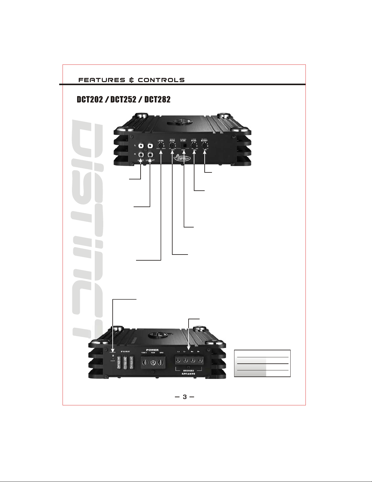
INPUT RCA JACKS
These inputs are for signal
cables from the source.
Always use high quality
shielded RCA cables.
INE OUT RCA JACKS
L
The LINE OUT allows you to
build multiple amplifier systems
with out having to use splitter
cords to distribute the signal.
Now it is simple a matter of
bringing one set of RCAs into
the first amplifier, then using
the line out RCA jacks as the
feed to the next amplifier.
INPUT LEVEL CONTROL
Enables the matching of input
levels to the output levels from
the head unit(or other signal
source).
POWER & PROTECTION INDICATORS
Provide instant information on status of amplifier,
including short-circuit and thermal overload alerts.
BASS BOOST CONTROL
Increases sound level in lower
frequencies by 18dB.
LOW PASS FILTER
When Crossover Mode Selector is in
Low Pass Mode, this control limits the
frequencies which will be distributed to
the speakers to those below the value
to which this is set within the range
50 Hz - 500 Hz.
CROSSOVER MODE SELECTOR
Determines the mode of built-in crossover:
low pass(permits only low frequency signals to
pass to speakers), high pass (permits only high
frequency signals to pass to speakers), or flat.
HIGH PASS FILTER
When Crossover Mode Selector is in High Pass
Mode, this control limits the frequencies which will
be distributed to the speakers to those above the
value to which this is set within the range
50 Hz - 500 Hz.
SPEAKER TERMINAL.
MODEL FUSES
DCT202
DCT252
DCT282
20A x 2
25A x 2
25A x 3
Page 5
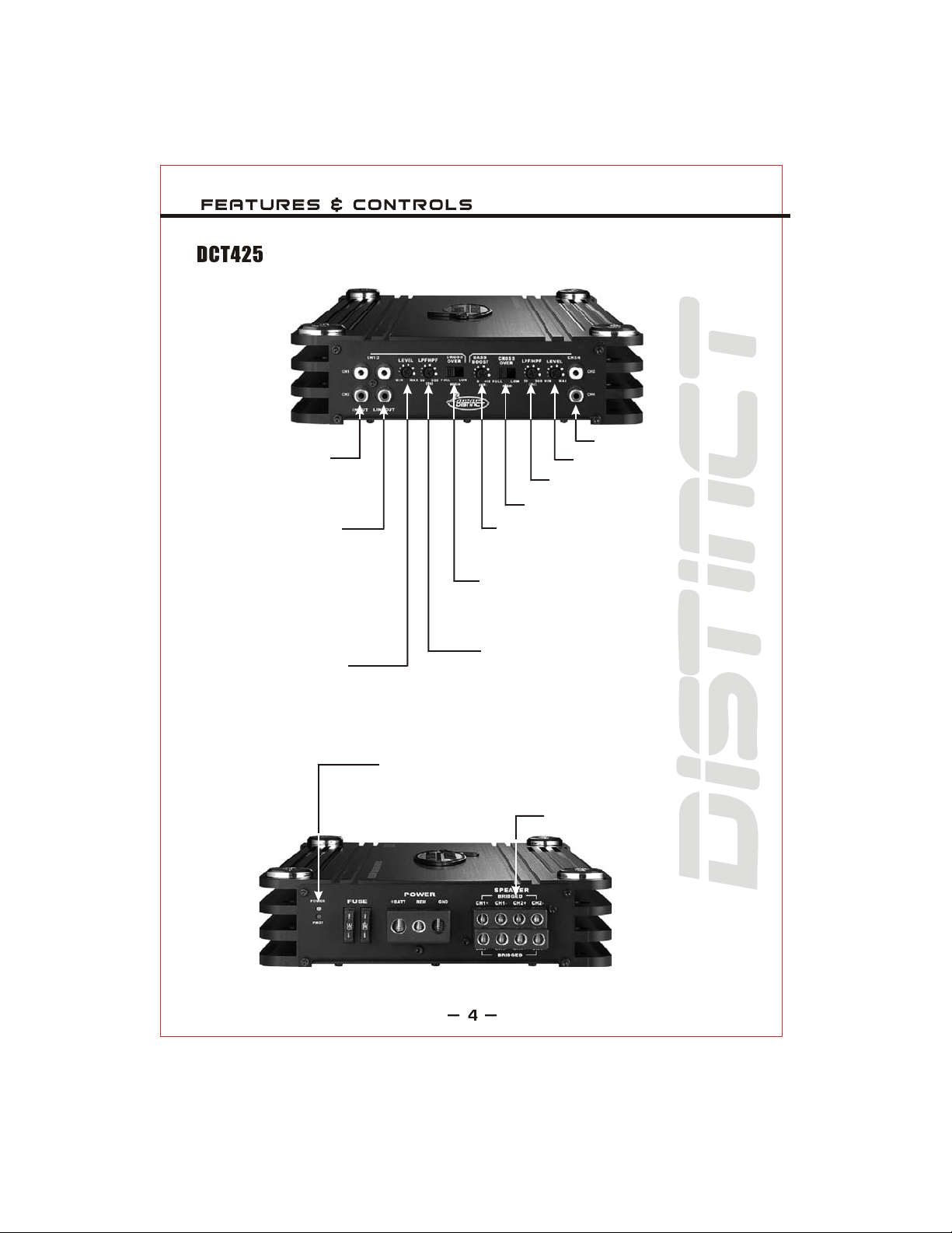
INPUT RCA JACKS
These inputs are for signal
cables from the source.
Always use high quality
shielded RCA cables.
INE OUT RCA JACKS
L
The LINE OUT allows you to
build multiple amplifier systems
with out having to use splitter
cords to distribute the signal.
Now it is simple a matter of
bringing one set of RCAs into
the first amplifier, then using
the line out RCA jacks as the
feed to the next amplifier.
INPUT LEVEL CONTROL
Enables the matching of input
levels to the output levels from
the head unit(or other signal
source).
INPUT RCA JACKS
INPUT LEVEL CONTROL
HIGH & LOW PASS FILTER
CROSSOVER MODE SELECTOR
BASS BOOST CONTROL
Increases sound level in lower
frequencies by 18dB.
CROSSOVER MODE SELECTOR
Determines the mode of built-in crossover:
low pass(permits only low frequency signals to
pass to speakers), high pass (permits only high
frequency signals to pass to speakers), or flat.
HIGH & LOW PASS FILTER
When Crossover Mode Selector is in High and
Low Pass Mode, this control limits the frequencies
which will be distributed to the speakers to those
above the value to which this is set within the range
50 Hz - 500 Hz.
POWER & PROTECTION INDICATORS
Provide instant information on status of amplifier,
including short-circuit and thermal overload alerts.
SPEAKER TERMINAL.
Page 6

Peak at 4 Ohms
RMS at 2 Ohms
At 4 Ohms Bridged
Speaker Impedance
T.H.D 4 Ohms Power
Frequency Response
Input Sensitivity
S/N Ratio
Channel Separation
Low Pass Filter
High Pass Filter
Bass Boost Control
Dimensions(inches)
Fuse(s)
1000W x 2
950W x 2
2000W x 1
2 Ohm
0.5%
10Hz ~40kHz
100mV~4V
>90dB
>65dB
50Hz~500Hz
50Hz~500Hz
0 ~+18dB
(60 Hz fixed)
8.66"x2.15"x9.45"
20A x 2
1500W x 2
1050W x 2
3000W x 1
2 Ohm
0.5%
10Hz ~40kHz
100mV~4V
>90dB
>65dB
50Hz~500Hz
50Hz~500Hz
0 ~+18dB
(60 Hz fixed)
8.66"x2.15"x11.42"
25A x 2
2000W x 2
1400W x 2
4000W x 1
2 Ohm
0.5%
10Hz ~40kHz
100mV~4V
>90dB
>65dB
50Hz~500Hz
50Hz~500Hz
0 ~+18dB
(60 Hz fixed)
8.66"x2.15"x15.35"
25 x 3
1000W x 4
750W x 4
2000W x 2
2 Ohm
0.5%
10Hz ~40kHz
100mV~4V
>90dB
>65dB
50Hz~500Hz
50Hz~500Hz
0 ~+18dB
(60 Hz fixed)
8.66"x2.15"x13.38"
30A x 2
Page 7

1. Find a suitable location in the vehicle to mount the amplifier.
2. Make sure there is sufficient air flow around the intended mounting location.
3. Bolt the amplifier to the mounting surface.
4. Connect the power ground terminal to the nearest point on the chassis of the car.
Keep this ground wire less than one meter (39") in length. Use 4 gauge or 0 gauge wire.
5. Connect the remote terminal to the remote output of the head unit using 14 gauge.
6. Connect an empty fuse holder within 300mm (12") of the battery and 4 gauge
or larger high quality cable from this fuse to the amplifier location.
7. Make sure there is no fuse in this fuse holder. Then make the connection to the "BATT"
connection on the amplifier.
8. If multiple amplifiers are being used, use cables (each with its own fuse at the battery)
or a #0 or a #2 cable from the fuse holder at the battery to a distribution block at or
near the amplifier's location.
9. Connect all line inputs and outputs using high-quality RCA-RCA cables.
10. Insert fuse(s) at the battery fuse holder(s).
11. Recheck all connections before powering up.
12. Set all level controls to their least sensitive positions and set all crossover controls,
switches, etc. to the desired frequency or position.
13. Once the system is powered up, set the volume control on the head unit to about the
2 o'clock position, and then set all the amplifiers' level controls for maximum output level.
14. Further fine tuning of the various controls may be necessary to obtain the desired
results.
Page 8

2 channel stereo configuration
TO OUTPUT FROM HEAT UNIT
FUSE
MODEL FUSES
DCT202
DCT252
DCT282
20A x 2
25A x 2
25A x 3
TO CAR STEREO
AUTO ANTENNA
LEFT
SPEAKER
SPEAKER
IMPEDANCE
2~4 OHM
RIGHT
SPEAKER
Page 9

2 channel bridged mode configuration
TO OUTPUT FROM HEAT UNIT
FUSE
MODEL FUSES
DCT202
DCT252
DCT282
20A x 2
25A x 2
25A x 3
SPEAKER
IMPEDANCE
4~8 OHM
TO CAR STEREO
AUTO ANTENNA
Page 10

2 channel tri-mode configuration
TO OUTPUT FROM HEAT UNIT
FUSE
MODEL FUSES
DCT202
DCT252
DCT282
20A x 2
25A x 2
25A x 3
TO CAR STEREO
AUTO ANTENNA
RIGHT
SPEAKER
LEFT
SPEAKER
SPEAKER
IMPEDANCE
4~8 OHM
Page 11

4 channel stereo configuration
TO OUTPUT FROM HEAT UNIT
1CH
SPEAKER
2CH
SPEAKER
FUSE
TO CAR STEREO
AUTO ANTENNA
4CH
SPEAKER
3CH
SPEAKER
Page 12

4 channel bridged mode configuration
TO OUTPUT FROM HEAT UNIT
SPEAKER
IMPEDANCE
4~8 OHM
FUSE
TO CAR STEREO
AUTO ANTENNA
SPEAKER
IMPEDANCE
4~8 OHM
Page 13

4 channel tri-mode configuration
TO OUTPUT FROM HEAT UNIT
1CH
SPEAKER
SPEAKER
IMPEDANCE
4~8 OHM
2CH
SPEAKER
FUSE
TO CAR STEREO
AUTO ANTENNA
SPEAKER
IMPEDANCE
4~8 OHM
4CH
SPEAKER
3CH
SPEAKER
Page 14

Page 15

STOP
STOP
STOP
+
4 ohm
_
+
2-channel Amplifier
(Operating in Stereo)
YES! NO!
Two 4-ohm speakers, wired in stereo,
will present a 4 ohm load to each
channel of the amplifier. Most twochannel amplifiers will work well in this
configuration.
4-channel Amplifier
(Operating in Stereo)
YES! NO!
Four 4-ohm speakers, wired in stereo,
will present a 4 ohm load to each
channel of the amplifier. Most fourchannel amplifiers will work well in this
configuration.
_
+
_
+
4 ohm
_
STOP
+
4 ohm
_
+
_
+
+
_
_
+
_
+
_
4 ohm
+
_
4 ohm
+
4 ohm
_
2-channel Amplifier
(Operating in
Bridged Mono)
Two 4-ohm speakers, wired in parallel
to a bridged two-channel amplifier,
will present a 2-ohm mono load to the
amplifier.
AMPLIFIERS DO NOT SUPPORT 2-OHM
MONO OPERATION! AMPLIFIER DAMAGE
COULD RESULT!
4-channel Amplifier
(Operating in
Bridged Mono)
Four 4-ohm speakers, wired in parallel
to a bridged four-channel amplifier,
will present a 4-ohm mono load to the
amplifier.
AMPLIFIERS DO NOT SUPPORT 2-OHM
MONO OPERATION! AMPLIFIER DAMAGE
COULD RESULT!
+
4 ohm
_
+
_
+
4 ohm
_
MOST TWO-CHANNEL
+
4 ohm
_
+
_
+
_
MOST FOUR-CHANNEL
4 ohm
+
_
4 ohm
+
_
4 ohm
+
_
Page 16

Lanzar Audio Inc.
1600 63rd Street, Brooklyn, NY 11204
(718)535-1800
www.lanzar.com
 Loading...