

Page 1
XPress DR
Industrial Device Server
User Guide
Part Number 900-772-R
Revision C December 2017
Page 2

Intellectual Property
© 2017 Lantronix, Inc. All rights reserved. No part of the contents of this publication may be
transmitted or reproduced in any form or by any means without the written permission of
Lantronix. Printed in the United States of America.
Lantronix is a registered trademark of Lantronix, Inc. in the United States and other countries.
DeviceInstaller and XPress are trademarks of Lantronix, Inc.
Patented: http://patents.lantronix.com
Windows is a trademark of Microsoft Corporation. All other trademarks and trade names are the
property of their respective holders.
Warranty
For details on the Lantronix warranty policy, please go to our Web site at
www.lantronix.com/support/warranty
Contacts
Lantronix, Inc.
7535 Irvine Center Drive
Suite 100
Irvine, CA 92618, USA
Phone: 949-453-3990
Fax: 949-453-3995
Technical Support
Online: www.lantronix.com/support
Sales Offices
For a current list of our domestic and international sales offices, go to the Lantronix web site at
www.lantronix.com/about/contact
; additional patents pending.
.
.
Disclaimer
All information contained herein is provided “AS IS.” Lantronix undertakes no obligation to update
the information in this publication. Lantronix does not make, and specifically disclaims, all
warranties of any kind (expressed, implied or otherwise) regarding title, non-infringement, fitness,
quality, accuracy, completeness, usefulness, suitability or performance of the information
provided herein. Lantronix shall have no liability whatsoever to any user for any damages, losses
and causes of action (whether in contract or in tort or otherwise) in connection with the user’s
access or usage of any of the information or content contained herein. The information and
specifications contained in this document are subject to change without notice.
Operation of this equipment in a residential area is likely to cause interference in which case the
user, at his or her own expense, will be required to take whatever measures may be required to
correct the interference.
Attention: This product has been designed to comply with the limits for a Class A digital device
pursuant to Part 15 of FCC Rules. These limits are designed to provide reasonable protection
against such interference when operating in a commercial environment. This equipment
generates, uses, and can radiate radio frequency energy, and if not installed and used in
accordance with this guide, may cause harmful interference to radio communications.
XPress™ DR Industrial Device Server User Guide 2
Page 3

Date
Rev.
Comments
Changes or modifications to the device not explicitly approved by Lantronix will void the user's
authority to operate the device.
The information in this guide may change without notice. The manufacturer assumes no
responsibility for any errors which may appear in this guide.
Revision History
February 2016 A Initial release.
May 2016 B Included Limited Power Source (LPS) information.
December 2017 C Updated enhanced password information.
XPress™ DR Industrial Device Server User Guide 3
Page 4

Table of Contents
Intellectual Property ______________________________________________________ 2
Warranty ______________________________________________________________ 2
Contacts _______________________________________________________________ 2
Disclaimer _____________________________________________________________ 2
Revision History _________________________________________________________ 3
List of Figures __________________________________________________________ 9
List of Tables ___________________________________________________________ 9
1: Using this Guide 11
Purpose and Audience __________________________________________________ 11
Chapter Summary ______________________________________________________ 11
Additional Documentation ________________________________________________ 12
2: Introduction 13
Applications ___________________________________________________________ 13
XPress™ DR Industrial Device Server ________________________________ 13
XPress DR-IAP Industrial Device Server ______________________________ 14
Protocol Support _______________________________________________________ 15
Industrial Automation Protocols _____________________________________ 15
Network Protocols (Standard Tunneling) ______________________________ 15
Additional Features _____________________________________________________ 15
Packing Algorithm ________________________________________________ 15
IP Address _____________________________________________________ 15
Port Number ____________________________________________________ 16
Configuration Methods __________________________________________________ 16
Dimensions ___________________________________________________________ 16
Product Information Label ________________________________________________ 17
3: Installation of the XPress DR Device Server 18
Package Contents ______________________________________________________ 18
Installing the XPress DR Unit _____________________________________________ 18
Required Information ____________________________________________________ 19
Hardware Address _______________________________________________ 19
Internet Protocol (IP) Address ______________________________________ 19
Port Number ____________________________________________________ 19
Methods for Assigning an IP Address _______________________________________ 20
4: Using DeviceInstaller 21
Installing DeviceInstaller _________________________________________________ 21
Assigning an IP Address _________________________________________________ 21
Adding the Unit to the Manage List _________________________________________ 22
XPress™ DR Industrial Device Server User Guide 4
Page 5

Table of Contents
Accessing the XPress DR Device Server Using DeviceInstaller ___________________ 22
Viewing the Current Configuration _________________________________________ 22
Next Step ______________________________________________________ 24
Assigning the IP Address: Serial Port Login __________________________________ 24
Saving Configuration ____________________________________________________ 24
Updating Configuration __________________________________________________ 25
5: Configuration Using Web Manager 28
Web Manager Page _____________________________________________________ 28
Device Status Home Page _________________________________________ 28
Apply Settings ___________________________________________________ 29
Apply Defaults __________________________________________________ 29
Network Configuration ___________________________________________________ 30
Automatic IP Address Configuration _________________________________ 30
Ethernet Configuration ____________________________________________ 31
Server Configuration ____________________________________________________ 32
Serial Tunnel - Hostlist Configuration _______________________________________ 34
Channel 1 - Serial Settings Configuration ____________________________________ 35
Serial Settings __________________________________________________ 35
Channel 1 – Connection Configuration ______________________________________ 37
Connection Settings - TCP _________________________________________ 37
Connection Settings - UDP_________________________________________ 40
6: Configuration via Telnet or Serial Port (Setup Mode) 42
Accessing the Setup Mode Window ________________________________________ 42
Telnet Connection _______________________________________________ 42
Serial Port Connection ____________________________________________ 44
Exiting Setup Mode _____________________________________________________ 44
7: Setup Mode: Server Configuration 45
Server Configuration (Option 0)____________________________________________ 45
IP Address _____________________________________________________ 45
Set Gateway IP Address __________________________________________ 45
Netmask: Number of Bits for Host Part _______________________________ 46
Set DNS Server IP Address ________________________________________ 46
Change Telnet/Web Configuration Password __________________________ 47
DHCP Naming __________________________________________________ 47
8: Channel Mode: Channel Configuration 48
Channel 1 (Option 1) ____________________________________________________ 48
Baudrate _______________________________________________________ 48
I/F (Interface) Mode ______________________________________________ 48
Flow __________________________________________________________ 49
Port Number ____________________________________________________ 50
Connect Mode __________________________________________________ 50
XPress™ DR Industrial Device Server User Guide 5
Page 6

Table of Contents
Send the Escape Sequence (+++) in Modem Mode _____________________ 53
Show IP addr after 'RING' _________________________________________ 53
Auto Increment Source Port ________________________________________ 53
Remote IP Address ______________________________________________ 53
Remote Port ____________________________________________________ 53
DisConnMode ___________________________________________________ 53
Flush Mode (Buffer Flushing) _______________________________________ 54
Pack Control ____________________________________________________ 54
DisConnTime (Inactivity Timeout) ___________________________________ 55
Send Characters _________________________________________________ 56
Telnet Terminal Type _____________________________________________ 56
Channel (Port) Password __________________________________________ 56
9: Setup Mode: Advanced Settings 57
Expert Settings (Option 5) ________________________________________________ 57
TCP Keepalive time in s ___________________________________________ 57
ARP Cache timeout in s ___________________________________________ 57
Disable Monitor Mode at Bootup ____________________________________ 57
HTTP Port Number _______________________________________________ 57
MTU Size ______________________________________________________ 57
TCP Re-Transmission Timeout _____________________________________ 58
Enable alternate MAC ____________________________________________ 58
Ethernet Connection Type _________________________________________ 58
Security Settings (Option 6) _______________________________________________ 58
Disable SNMP __________________________________________________ 58
SNMP Community Name __________________________________________ 59
Disable Telnet Setup _____________________________________________ 59
Disable TFTP Firmware Upgrade ____________________________________ 59
Disable Port 77FE (Hex) ___________________________________________ 59
77FEh Access Mode _____________________________________________ 59
Disable Web Server ______________________________________________ 59
Disable Web Setup _______________________________________________ 60
Disable ECHO Ports ______________________________________________ 60
Enable Enhanced Password _______________________________________ 60
Default Settings (Option 7) _______________________________________________ 60
Exit Configuration Mode (Option 8 or Option 9) _______________________________ 60
10: Firmware Upgrades 61
Obtaining Firmware _____________________________________________________ 61
Reloading Firmware ____________________________________________________ 61
Using TFTP Graphical User Interface ________________________________ 61
Distributing Firmware to Another Unit ________________________________ 62
Using HyperTerminal _____________________________________________ 62
XPress™ DR Industrial Device Server User Guide 6
Page 7

Table of Contents
11: Monitor Mode 64
Entering Monitor Mode Via the Serial Port _____________________________ 64
Entering Monitor Mode Via the Network Port ___________________________ 64
Monitor Mode Commands _________________________________________ 64
12: Com Port Redirector 67
A: Troubleshooting & Technical Support 68
LEDs ________________________________________________________________ 68
Problems and Error Messages ____________________________________________ 69
Lantronix Technical Support ______________________________________________ 71
B: Network Configuration Using UDP 72
UDP Datagrams _______________________________________________________ 72
Configuring Multiple Devices ______________________________________________ 73
Acquiring a Valid Setup Record _____________________________________ 73
Sending a Setup Record __________________________________________ 74
The Intel Hex Format _____________________________________________ 75
Calculating the Checksum _________________________________________ 75
Calculating the Two’s Complement __________________________________ 76
Setup Records _________________________________________________________ 76
Channel Parameters ______________________________________________ 77
Interface Mode __________________________________________________ 77
Baud Rate ______________________________________________________ 78
Flow Control ____________________________________________________ 78
Connect Mode __________________________________________________ 79
Disconnect Mode ________________________________________________ 79
Flush Mode (Buffer Flushing) _______________________________________ 80
Pack Control ____________________________________________________ 81
IP Addresses __________________________________________________________ 81
Network Portion _________________________________________________ 81
Subnet Portion __________________________________________________ 82
Host Portion ____________________________________________________ 82
Network Address ________________________________________________ 82
Broadcast Address _______________________________________________ 82
IP Subnet Mask _________________________________________________ 82
Private IP Networks and the Internet _________________________________ 83
Network RFCs __________________________________________________ 83
C: Connections and Pinouts 84
Serial Interface ________________________________________________________ 84
RJ-45 Serial Connector __________________________________________________ 84
Screw Terminal Serial Connectors _________________________________________ 85
RJ-45 Ethernet Interface _________________________________________________ 85
XPress™ DR Industrial Device Server User Guide 7
Page 8

Table of Contents
Serial Interface Connections ______________________________________________ 86
9-Pin RS-232 to Serial RJ-45 _______________________________________ 86
9-Pin RS-232 to Serial Screw Terminals ______________________________ 86
Front Panel Description __________________________________________________ 87
Power Requirements ____________________________________________________ 89
Reset Switch __________________________________________________________ 89
RS-232/RS-485 Switch __________________________________________________ 89
D: Technical Specifications 90
E: Alternative Ways to Assign an IP Address 91
DHCP ________________________________________________________________ 91
AutoIP _______________________________________________________________ 91
Class A Network _________________________________________________ 92
Class B Network _________________________________________________ 92
Class C Network _________________________________________________ 92
Network Address ________________________________________________ 92
Broadcast Address _______________________________________________ 92
IP Netmask _____________________________________________________ 92
Private IP Networks and the Internet _________________________________ 93
Network RFCs __________________________________________________ 93
BOOTP ______________________________________________________________ 94
ARP and Telnet ________________________________________________________ 94
F: Binary to Hex Conversion 95
Converting Binary to Hexadecimal _________________________________________ 95
Conversion Table ________________________________________________ 95
Scientific Calculator ______________________________________________ 95
Connect Mode Options __________________________________________________ 96
Disconnect Mode Options ________________________________________________ 98
Flush Mode (Buffer Flushing) Options ______________________________________ 100
Interface Mode Options _________________________________________________ 105
Pack Control Options ___________________________________________________ 106
G: Compliance 108
Compliance Information Emission/Susceptibility ______________________________ 108
RoHS, REACH and WEEE Compliance Statement ___________________________ 109
XPress™ DR Industrial Device Server User Guide 8
Page 9

List of Figures
Table of Contents
Figure 2-1 XPress DR ___________________________________________________ 13
Figure 2-2 RS-485 Multidrop with XPress DR-IAP _____________________________ 14
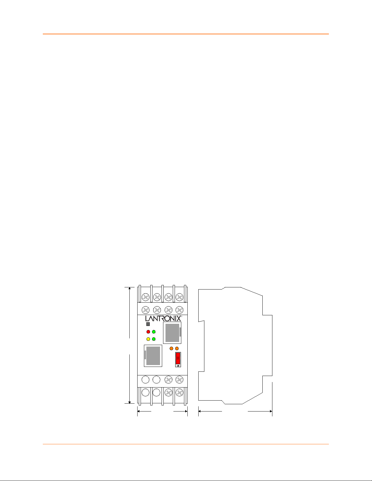
Figure 2-3 Product Dimensions ____________________________________________ 16
Figure 2-4 Product Information Label _______________________________________ 17
Figure 3-1 XPress DR Connected to Serial Device and Network __________________ 18
Figure 5-1 Device Status Home Page _______________________________________ 28
Figure 5-2 Apply Settings and Apply Defaults _________________________________ 29
Figure 5-3 Network Settings ______________________________________________ 30
Figure 5-4 Server Settings ________________________________________________ 32
Figure 5-5 Hostlist Settings _______________________________________________ 34
Figure 5-6 Channel Serial Settings _________________________________________ 35
Figure 5-7 TCP Connection Settings ________________________________________ 37
Figure 5-8 UDP Connection Settings _______________________________________ 40
Figure 6-1 Setup Mode Window (Standard Tunneling) __________________________ 43
Figure 10-1 TFTP Dialog Box _____________________________________________ 62
Figure A-1 Product Information label ________________________________________ 68
Figure C-1 Serial Screw Terminal Pinouts ___________________________________ 85
Figure C-2 RJ-45 Connector ______________________________________________ 86
Figure C-3 RS-232 to Serial RJ-45 Connection _______________________________ 86
Figure C-4 RS-232 Configuration __________________________________________ 86
Figure C-5 Front Panel Layout ____________________________________________ 87
Figure C-6 Power Requirements ___________________________________________ 89
Figure C-7 Reset Switch _________________________________________________ 89
Figure C-8 RS-232/RS-485 Switch _________________________________________ 89
List of Tables
Table 3-1 Methods for Assigning IP Addresses _______________________________ 20
Table 4-1 XPress DR Configuration in DeviceInstaller __________________________ 22
Table 7-1 BootP/DHCP/AutoIP Options _____________________________________ 45
Table 7-2 Standard IP Network Netmasks ___________________________________ 46
Table 7-3 Netmask Examples _____________________________________________ 46
Table 8-1 Interface Mode Options __________________________________________ 49
Table 8-2 Common Interface Mode Settings __________________________________ 49
Table 8-3 Flow Control Options ____________________________________________ 49
Table 8-4 Port Numbers _________________________________________________ 50
Table 8-5 Connect Mode Options __________________________________________ 50
Table 8-6 Manual Connection Address Example ______________________________ 51
Table 8-7 Modem Mode Commands ________________________________________ 52
XPress™ DR Industrial Device Server User Guide 9
Page 10

Table of Contents
Table 8-8 Disconnect Mode Options ________________________________________ 53
Table 8-9 Flush Mode Options ____________________________________________ 54
Table 8-10 Pack Control Options __________________________________________ 55
Table 10-1 Protocol Firmware _____________________________________________ 61
Table 11-1 Monitor Mode Commands _______________________________________ 64
Table 11-2 Command Response Codes _____________________________________ 66
Table A-1 XPress DR LED Functions ______________________________________ 68
Table A-2 LED Error Indications ___________________________________________ 68
Table A-3 Problems and Error Messages ____________________________________ 69
Table B-1 UDP Configuration _____________________________________________ 72
Table B-2 Block Types __________________________________________________ 75
Table B-3 Setup Record Construction _______________________________________ 76
Table B-4 Channel Parameters ____________________________________________ 77
Table B-5 Interface Mode Options _________________________________________ 77
Table B-6 Common Interface Mode Settings _________________________________ 78
Table B-7 Baud Rate Settings _____________________________________________ 78
Table B-8 Flow Control Options ___________________________________________ 78
Table B-9 Connect Mode Options __________________________________________ 79
Table B-10 Disconnect Mode Options _______________________________________ 79
Table B-11 Flush Mode Options ___________________________________________ 80
Table B-12 Pack Control Options __________________________________________ 81
Table B-13 Network Portion of IP Address ___________________________________ 81
Table B-14 Available IP Addresses _________________________________________ 82
Table B-15 Standard IP Network Netmasks __________________________________ 83
Table B-16 Netmask Examples ____________________________________________ 83
Table C-1 Serial RJ45 Pinouts ____________________________________________ 84
Table C-2 Serial Screw Terminal Pinouts ____________________________________ 85
Table C-3 Ethernet Interface Signals _______________________________________ 85
Table C-4 Front Panel Components ________________________________________ 88
Table D-1 Technical Specification __________________________________________ 90
Table F-1 Binary to Hexadecimal Conversion Table ____________________________ 95
Table F-2 Connect Mode Options __________________________________________ 96
Table F-3 Connect Mode Options for Modem Emulation ________________________ 98
Table F-4 Disconnect Mode Options ________________________________________ 98
Table F-5 Flush Mode Options ___________________________________________ 100
Table F-6 Interface Mode Options _________________________________________ 105
Table F-7 Pack Control Options __________________________________________ 106
XPress™ DR Industrial Device Server User Guide 10
Page 11

Chapter
Description
7: Setup Mode: Server
8: Channel Mode: Channel
9: Setup Mode: Advanced
10: Firmware Upgrades
11: Monitor Mode
1: Using this Guide
Purpose and Audience
This user guide describes the family of Lantronix® XPress™ DR device servers, including the
XPress DR device server and the XPress DR-IAP device server with support for Industrial
Automation Protocols (IAP).
Most of the material in this manual applies to all of the XPress DR products. However, in some
cases there will be some features that apply to only one product. In those cases, a note will
explain the variation.
Note: In most cases XPress DR refers to both the XPress DR and the XPress DR-IAP industrial
device servers.
Chapter Summary
2: Introduction
3: Installation of the XPress
DR Device Server
4: Using DeviceInstaller
5: Configuration Using Web
Manager
6: Configuration via Telnet
or Serial Port (Setup Mode)
Configuration
Configuration
Settings
Describes the main features of the XPress DR device server and the
protocols supported.
Provides information for installing your unit and getting it up and running
using DeviceInstaller or a serial port connection.
Instructions for viewing the current configuration using DeviceInstaller
application.
Details using the Web-Manager to set parameters such as port and server
properties.
Provides instructions for accessing Setup Mode (command line interface)
using a Telnet connection through the network or a terminal or terminal
emulation program through the serial port.
Details the network (server) settings
Details the serial port settings.
Details expert and security settings and explains how to reset the unit to
factory default values.
Provides instructions for obtaining the latest firmware and updating the
XPress DR.
XPress™ DR Industrial Device Server User Guide 11
12: Com Port Redirector
A: Troubleshooting &
Technical Support
Provides instructions for accessing and using the command line interface to
monitor the network and diagnose problems.
Provides an introduction to the Com Port Redirector and where to download
the software online.
Describes common problems and error messages and how to contact
Lantronix Technical Support.
Page 12
1: Using this Guide
Server Quick Start Guide
B: Network Configuration
Using UDP
C: Connections and Pinouts
D: Technical Specifications
E: Alternative Ways to
Assign an IP Address
F: Binary to Hex Conversion
G: Compliance
Describes how to configure and query the device server over the network
using UDP datagrams.
Provides descriptions and illustrations of connection hardware.
Lists technical specifications for the XPress DR.
Provides detailed information about using DHCP, AutoIP, BOOTP ARP, and
Telnet to assign an IP address.
Provides instructions for converting binary values to hexadecimals.
Provides Lantronix compliance information.
Additional Documentation
Visit the Lantronix Web site at www.lantronix.com/support/documentation for the latest
documentation and the following additional documentation.
Document Description
XPress DR Industrial Device
DeviceInstaller Online Help
“Live” Tutorials on the Lantronix
Web Site (English)
Provides the steps for getting the XPress DR device server
up and running.
Provides instructions for using the Windows® operating
system-based utility to configure the XPress DR and other
Lantronix device servers.
Explain and demonstrate assigning an IP address to the
XPress DR device server and setting it up with the Com Port
Redirector. See
http://ltxfaq.custhelp.com/app/answers/detail/a_id/1119
.
Com Port Redirector Quick Start
Guide
Provides information on using the Windows operating
system-based utility to create a virtual com port.
XPress™ DR Industrial Device Server User Guide 12
Page 13

2: Introduction
Applications
XPress™ DR Industrial Device Server
The XPress DR device server connects serial devices to Ethernet networks using the IP protocol
family (TCP for connection-oriented stream applications and UDP for datagram applications). A
few of the different types of serial devices supported are listed below:
Time/Attendance Clocks and Terminals
ATM Machines
CNC Controllers
Data Collection Devices
Universal Power Supply (UPS) Management Units
Telecommunications Equipment
Data Display Devices
Security Alarms and Access Control Devices
Handheld Instruments
Modems
2: Introduction
The XPress DR connects these devices through a TCP data channel or through a Telnet
connection to computers or another device server. Datagrams can be sent by UDP.
Figure 2-1 XPress DR
The XPress DR supports RS-232, RS-422/485 via its screw terminals and RJ45 serial port. It
supports 10/100 megabytes per second (Mbps) Ethernet through the RJ-45 connector. It can be
configured via HTTP, SNMP, DHCP or Telnet. It contains a flash ROM for easy software
upgrades.
XPress™ DR Industrial Device Server User Guide 13
Page 14

2: Introduction
PLCs XPress DR-IAP
XPress DR-IAP Industrial Device Server
Note: This section is for the XPress DR-IAP only.
The Lantronix Industrial Automation Platform (IAP) family of device servers allows a single
network and protocol to connect multiple serial devices from many vendors. IAP provides the
automation industry with a network-enabling solution using TCP/IP and standard Ethernet
networks that is vendor-independent.
By encapsulating serial data and transporting it over Ethernet, the device server allows virtual
serial links to be established over Ethernet and IP (TCP/IP, UDP/IP) networks. As a result, limited
distance, point-to-point, direct serial connections can be extended within the plant, throughout the
facility, or across the global enterprise. The following picture is one of the device servers in the
IAP family.
Figure 2-1 RS-485 Multidrop with XPress DR-IAP
Lantronix provides IAP device servers are specifically designed for different industrial
environments.
XPress DR-IAP, with DIN rail interface for harsh environments or alongside control
instruments in electrical panels
UDS1100-IAP, a rugged device server for use in applications that require a wide operating
temperature range (-40 to 70°C)
xDirect-IAP, a compact device server with multiple power options including PoE and wide
operating temperature range (-40 to 85°C)
A few examples of attached devices are:
PLCs
AC/DC drives
CNC systems
Operator panels and message displays
Process Controls
Instrumentation
Power monitoring equipment
Scales and weighing systems
Barcode scanners
Label printers
Most factory floor serial devices
XPress™ DR Industrial Device Server User Guide 14
Page 15

Protocol Support
Industrial Automation Protocols
IAP device servers, adapted to multiple factory environments, can unite any mixture of equipment
from industrial automation vendors into a single reliable pipeline. This new and open
infrastructure opens the way for data to flow in real time from all your plant devices up to your IT
layer.
IAP device servers are delivered with IAP Standard Tunneling protocol and can be loaded with
industrial communication protocols. Where the IAP Standard Tunneling protocol is limited to
exclusive, standard ASCII device-to-device connections, the industrial protocols offer connections
to other devices that require special formatting or features simultaneously.
For information about using any of the industrial communication protocols, see user manuals and
protocol firmware files available at www.lantronix.com/downloads
2: Introduction
.
You can set up the unit using the serial port, or remotely over Ethernet using Telnet or a web
browser. The Lantronix® DeviceInstaller™ application, a Windows
that simplifies the process of installing protocols and configuring them for use with attached
devices. The DeviceInstaller application is also available for download at
www.lantronix.com/downloads
free, non-volatile storage which allows for fast system upgrades.
Network Protocols (Standard Tunneling)
The XPress DR uses TCP/IP protocols for network communication. The supported standards are:
ARP, UDP, TCP, ICMP, Telnet, TFTP, DHCP, AutoIP, and SNMP. For transparent connections,
TCP/IP (binary stream) or Telnet protocols are used. Firmware upgrades can be made with the
TFTP protocol.
The IP (Internet Protocol) protocol defines addressing, routing, and data-block handling over the
network. The TCP (transmission control protocol) assures that no data is lost or duplicated, and
that everything sent into the connection on one side arrives at the target exactly as it was sent.
For typical datagram applications where devices interact with others without maintaining a pointto-point connection, UDP datagram is used.
Additional Features
Packing Algorithm
The two available packet algorithms (which define how and when packets are sent to the
network) are software selectable. The standard algorithm is optimized for applications where
XPress DR is used in a local environment, allowing for very small delays for single characters
while trying to keep the packet count low. The alternate packing algorithm minimizes the packet
count on the network and is especially useful for applications in routed Wide Area Networks.
Various parameters can be set in this mode to economize the serial data stream.
based configuration software
. XPress DR device servers use flash memory for maintenance-
IP Address
Every active device connected to the TCP/IP network must have a unique IP address. This IP
address is used to reference a specific device, for example, to build a connection to XPress DR’s
serial port. See E: Alternative Ways to Assign an IP Address for a complete description of IP
Addressing.
XPress™ DR Industrial Device Server User Guide 15
Page 16
95MM
(3.7 in)
35MM
(1.4 in)
60MM
(2.4 in)
RESET
10/100BASE-T SERIAL
RS232
RS485
F R
A L
Port Number
A destination IP address and a port number define every TCP connection and every UDP
datagram. A port number is necessary to address an application or a channel on a network host.
The port number can be compared to an extension on a PBX system.
A Telnet application (login to a host with an ASCII terminal) is commonly assigned TCP port
number 23. More than one Telnet connection can be established to one host using the Telnet
port; however, the other peer IP address/port number combinations must be different.
In the XPress DR, a port number can be configured on the channel (port). The XPress DR uses
this port number for outgoing messages and incoming connections, or UDP datagrams, which are
addressed to its port number. Port 9999 (decimal) is used for remote configuration.
Configuration Methods
After installation, the XPress DR requires configuration. For the unit to operate correctly on a
network, it must have a unique IP address on the network. There are three basic methods for
logging into the XPress DR and assigning IP addresses and other configurable settings:
DeviceInstaller: Configure the IP address and other network settings on the XPress DR using a
Graphical User Interface (GUI) on a PC attached to a network. See 4: Using DeviceInstaller.
Web-Manager: Through a web browser, configure the XPress DR settings using the Lantronix
Web-Manager. See 5: Configuration Using Web Manager.
2: Introduction
Dimensions
Serial and Telnet Ports: Use Setup Mode, a command line interface. There are two approaches
to accessing Setup Mode: making a Telnet connection to the network port (9999) or connecting a
terminal (or a PC running a terminal emulation program) to the unit’s serial port.
See 6: Configuration via Telnet or Serial Port (Setup Mode).
The XPress DR dimensions are shown in the following drawing.
Figure 2-3 Product Dimensions
XPress™ DR Industrial Device Server User Guide 16
Page 17
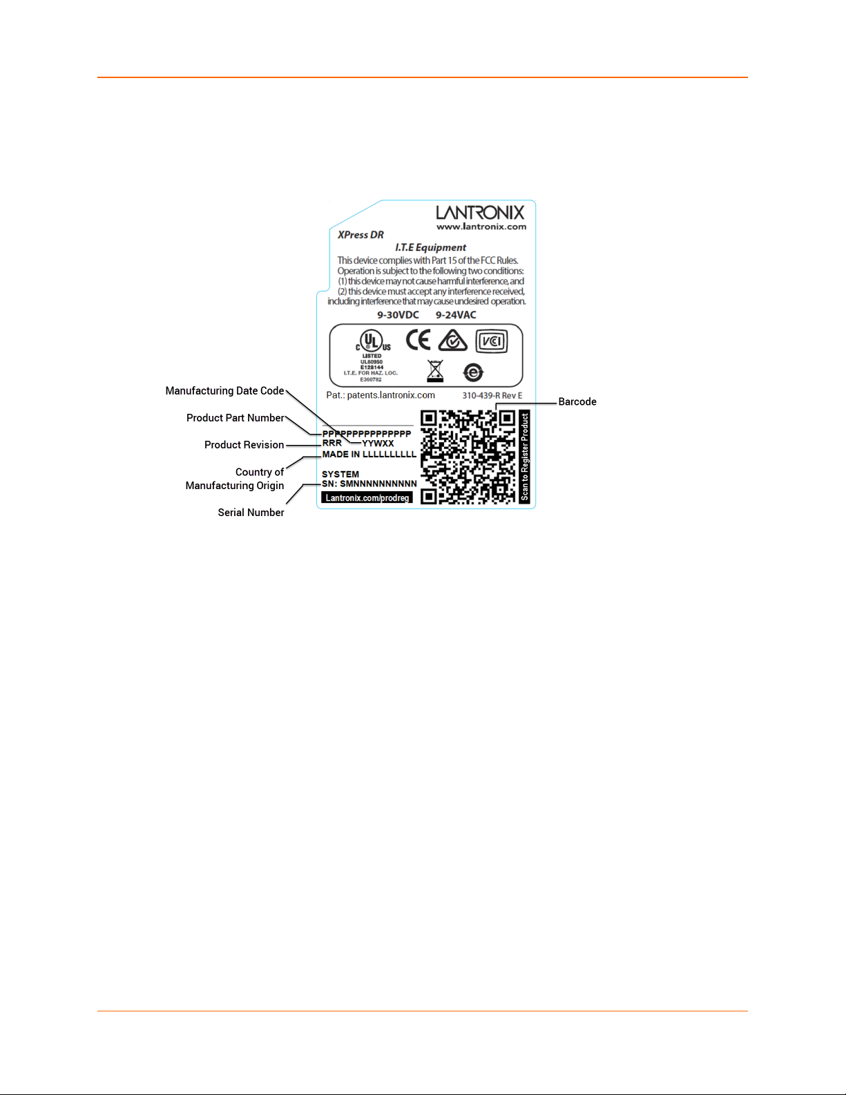
Product Information Label
The product information label on your XPress DR or XPress DR-IAP industrial device server
contains important information about your unit.
Figure 2-4 Product Information Label
2: Introduction
Notes: Before mounting the
device on a DIN rail, copy the
information from the label.
XPress™ DR Industrial Device Server User Guide 17
Page 18
3: Installation of the XPress DR Device Server
RESET
10/100BASE-T
SERIAL
RS232
RS485
F R
A L
3: Installation of the XPress DR Device Server
This section describes how to install your XPress DR device server and get it up and running in
the shortest possible time.
XPress DR comes with standard tunnel protocol and the XPress DR-IAP comes with the IAP
standard tunnel protocol. Both versions are similar but cannot be interchanged. Standard
tunneling is a serial communications protocol used by most Lantronix device servers. It can be
configured to Ethernet-enable most serial devices such as barcode scanners, weigh scales,
operator panels, data access devices, alpha numeric displays, and thousands of intelligent serial
devices. For XPress DR-IAP users, see Industrial Automation Protocols.
Loading industrial protocols to an XPress DR-IAP, such as IAP Modbus Bridge, may remove the
web pages and change the configure dialogs. See the user manuals on individual protocols for
protocol specific settings and configuration dialogs. Protocol manuals are found at
www.lantronix.com/downloads
Standard Tunnel Protocol.
Note: The following information is based on the condition that a XPress DR is loaded with
Standard Tunnel Protocol. The XPress DR-IAP with IAP Standard Tunnel Protocol has the same
options available.
. This section describes the setup and configuration dialogs for the
Package Contents
Verify and inspect the contents of your XPress DR device server package using the following list.
XPress DR or XPress DR-IAP industrial device server
XPress DR Industrial Device Server Quick Start Guide
Installing the XPress DR Unit
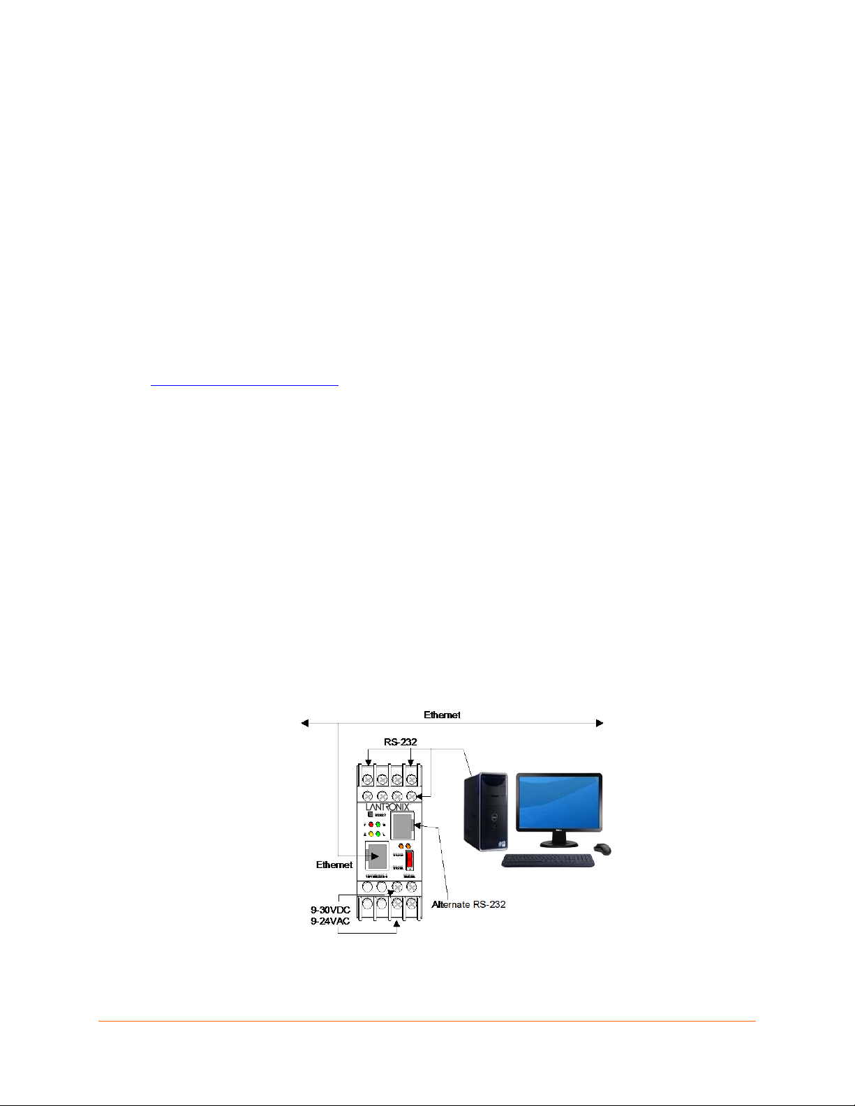
The following diagram shows a typical hardware configuration for the XPress DR unit. Use one of
the cables described in Serial Interface Connections to connect a PC COM port to the XPress DR
device server.
Figure 3-1 XPress DR Connected to Serial Device and Network
XPress™ DR Industrial Device Server User Guide 18
Page 19

To install the unit
1. Connect a serial device to your XPress DR. See Serial Interface Connections for more
information about cable and connector specifications.
2. Connect an Ethernet cable to the Ethernet port.
3. Supply power to your XPress DR using a 9-30VDC or 9-24VAC source.
Note: The required input voltage is 9-30VDC, 9-24VAC (3 W maximum).
4. Supply power to the serial device.
Note: Connecting a device to an active Ethernet network can disrupt communications on the
network. Make sure the device is configured for your application before connecting to an active
network.
Required Information
Before configuring the XPress DR device server, have the following information available:
Hardware Address
Take note of the unit’s hardware address (also known as the Ethernet or MAC address.) It is on
the Product Information Label. The first three bytes of the hardware Address are fixed and read
00-80-A3, identifying the unit as a Lantronix product. The fourth, fifth, and sixth bytes are unique
numbers assigned to each unit.
3: Installation of the XPress DR Device Server
00-80-A3-21-18-17 or 00:80:A3:21:18:17
Internet Protocol (IP) Address
The XPress DR device server must have a unique IP address on your network. This address
references the specific unit. By default, the unit is DHCP-enabled and automatically assigned an
IP address on DHCP-enabled networks. If you are assigning a static IP address, the systems
administrator generally provides the IP address, subnet mask, and gateway.
Note: The factory default IP address is 0.0.0.0 to enable DHCP, BOOTP, and AutoIP. When the
units boots, it sends a DHCP broadcast to try and get an IP address. If it receives no reply from a
DHCP server, the XPress DR tries BOOTP. If the XPress DR does not receive a response from
BOOTP, it reverts to an AutoIP address.
IP Address: ______ ______ ______ ______
Subnet Mask: ______ ______ ______ ______
Gateway: ______ ______ ______ ______
You have several options for assigning an IP address and related network settings to your unit.
This chapter provides information about using the DeviceInstaller (graphical user interface) and
serial port login (command line interface) methods.
Note: For information about other methods of assigning the IP address, such as DHCP, AutoIP,
ARP, and Telnet, see Alternative Ways to Assign an IP Address.
Port Number
Every TCP connection and every UDP datagram is defined by a destination IP address and a port
number. For example, a Telnet application commonly uses port number 23. A port number is
similar to an extension on a PBX system.
XPress™ DR Industrial Device Server User Guide 19
Page 20

Method
Description
The unit's serial channel (port) can be associated with a specific TCP/UDP port number. Port
number 9999 is reserved for access to the unit's Setup (configuration) Mode window.
Methods for Assigning an IP Address
The unit's IP address must be configured before a network connection is available. You have the
following options for assigning an IP to your unit:
Table 3-1 Methods for Assigning IP Addresses
3: Installation of the XPress DR Device Server
DHCP
DeviceInstaller
(Recommended)
ARP and Telnet
AutoIP
Serial Port Login
A DHCP server automatically assigns the IP address and network settings. See
DHCP.
You can manually assign the IP address using a graphical user interface (GUI) on a
PC attached to a network.
You manually assign the IP address and other network settings at a command
prompt using a UNIX or Windows-based system. Only one person at a time can be
logged into the configuration port (port 9999). This eliminates the possibility of several
people simultaneously attempting to configure the unit. See ARP and Telnet.
This automatic method is appropriate when you have a small group of hosts rather
than a large network. This method allows the hosts to negotiate with each other and
assign addresses, in effect creating a small network. See AutoIP.
You initially configure the unit through a serial connection. See Assigning the IP
Address: Serial Port Login.
These methods are described in the remaining sections of this chapter.
Note: In most installations, a fixed IP address is desirable. The systems administrator generally
provides the IP address.
Obtain the following information before starting to set up your unit:
IP Address: ______ ______ ______ ______
Subnet Mask: ______ ______ ______ ______
Gateway: ______ ______ ______ ______
XPress™ DR Industrial Device Server User Guide 20
Page 21

4: Using DeviceInstaller
This chapter covers the steps for getting the XPress DR industrial device server online, for
viewing its current configuration, and for saving and upgrading device configurations.
Note: DeviceInstaller is a free utility program provided by Lantronix that discovers, configures,
upgrades, and manages Lantronix device servers. It can be downloaded from the Lantronix
website at www.lantronix.com/support/downloads
configure the IP address and related settings or for more advanced features, see the
DeviceInstaller Online Help.
Installing DeviceInstaller
1. Download the latest version of DeviceInstaller from www.lantronix.com/support/downloads.
2. Run the executable to start the installation process.
3. Respond to the installation wizard prompts. (If prompted to select an installation type, select
Typical).
Assigning an IP Address
. For instructions on using DeviceInstaller to
The unit’s IP address must be configured before it can work correctly on a network. The unit’s IP
address is normally set to 0.0.0.0 at the factory. The hardware address is on the product label.
The unit is DHCP enabled as the default.
1. Click Start -> All Programs -> Lantronix ->DeviceInstaller 4.4 -> DeviceInstaller. If your
PC has more than one network adapter, a message displays. Select an adapter and click OK.
Note: If the unit already has an IP address (e.g., DHCP has assigned an IP address), click
the Search icon and select the unit from the list of Lantronix device servers on the local
network.
2. Click the Assign IP icon.
3. If prompted, enter the hardware address (on the product label) and click Next.
4. Select Assign a specific IP address and click Next.
5. Enter the IP address. The Subnet mask displays automatically based on the IP address; if
desired, you may change it. On a local network, you can leave the Default gateway blank (all
zeros). Click Next.
6. Click the Assign button and wait several seconds until a confirmation message displays.
7. Click Finish.
8. Select the device from the main window list and select Ping from the Tools menu. The Ping
Device dialog box shows the IP address of the selected unit.
9. From the Tools menu, click the Ping button. The results display in the Status window. Click
the Clear Status button to clear the window so you can ping the device again.
Note: If you do not receive “Reply” messages, make sure the unit is attached to the network
properly and the IP address assigned is valid for the particular network segment you are
working with. If you are not sure, check with your systems administrator.
XPress™ DR Industrial Device Server User Guide 21
Page 22

4: Using DeviceInstaller
Configurable field. A name that identifies the XPress. The name field is blank
DeviceInstaller application.
Non-configurable field. Displays the name associated with XPress unit’s
current IP address, if the IP address was obtained dynamically.
Configurable field. A group name to categorize the XPress device server.
group name is not visible on other PCs or laptops using DeviceInstaller.
Comments
Configurable field. Information about the XPress device server. Double-click
comment is not visible on other PCs or laptops using DeviceInstaller.
Adding the Unit to the Manage List
Now add the unit to the list of similar Lantronix devices on the network so you can manage and
configure it. To perform this step, click the Search icon.
DeviceInstaller locates the unit and adds it to the list. Now you can manage (configure) the unit so
it works with the serial device on the network.
Accessing the XPress DR Device Server Using DeviceInstaller
1. If DeviceInstaller has not already been installed, run the executable to start the installation
process and respond to the installation wizard prompts. (If prompted to select an installation
type, select Typical.)
2. Click Start -> All Programs -> Lantronix -> DeviceInstaller 4.4 -> DeviceInstaller.
3. When DeviceInstaller starts, it will perform a network device search. To perform another
search, click Search.
4. Expand the xPress folder by clicking the + symbol next to the folder icon. The list of available
Lantronix XPress DR and XPress DR-IAP devices appear.
5. Select the XPress unit by expanding its entry and clicking on its IP address to view its
configuration.
6. On the right side of the page, click the Device Info tab. The current XPress device
configuration appears.
Viewing the Current Configuration
DeviceInstaller provides a view of the unit's configuration.
1. Follow the instructions above to locate the XPress device server.
2. In the right pane, click the Device Info tab. The current XPress device server configuration
displays.
Table 4-1 XPress DR Configuration in DeviceInstaller
Current Settings Description
Name
DHCP Device Name
Group
Device Family
Type
ID
by default. Double-click the field, type in the value, and press Enter to
complete. This name is not visible on other PCs or laptops using the
Double-click the field, type in the value, and press Enter to complete. This
the field, type in the value, and press Enter to complete. This description or
Non-configurable field. Displays the XPress device server’s device family as
“xPress”.
Non-configurable field. Displays the device type as “xPress DR” or “xPress DRIAP”.
Non-configurable field. Displays the XPress device server’s ID embedded
within the unit.
XPress™ DR Industrial Device Server User Guide 22
Page 23

Non-configurable field. Displays the XPress device server’s hardware (or MAC)
address.
Non-configurable field. Displays the firmware currently installed on the XPress
device server.
Extended Firmware
Non-configurable field. Displays the extended firmware currently installed on
Non-configurable field. Displays the XPress device server’s status as online,
(the XPress device server is currently performing a task).
Non-configurable field. Displays the XPress device server’s current IP address.
To change the IP address, see Assigning an IP Address.
IP Address was
Non-configurable field. Displays “Dynamically” if the XPress device server
Non-configurable field. Displays the XPress device server’s current subnet
mask. To change the subnet mask, see Assigning an IP Address.
Non-configurable field. Displays the XPress device server’s current gateway.
To change the gateway, see Assigning an IP Address.
TCP Keepalive
Non-configurable field. Displays the XPress device server’s TCP keepalive
value. The value is in the range 1-65s, and the default setting is 45.
Non-configurable field. Indicates if Telnet sessions are permitted. Displays
True.
Non-configurable field. Displays the XPress device server’s port for Web
Manager configuration.
Non-configurable field. Displays the XPress unit’s maximum baud rate.
Firmware Upgradable
Non-configurable field. Displays True, indicating the XPress device server’s
firmware is upgradable as newer version become available.
Supports 921K Baud
False
Current Settings Description
Hardware Address
Firmware Version
4: Using DeviceInstaller
Version
Online Status
IP Address
Obtained
Subnet Mask
Gateway
Number of COB
partitions supported
Number of Serial
Ports
Telnet Supported
the XPress device server.
offline, unreachable (the XPress device server is on a different subnet), or busy
automatically received an IP address (e.g., from DHCP). Displays “Statically” if
the IP address was configured manually. If the IP address was assigned
dynamically, the following fields appear:
Obtain with DHCP with value of True or False
Obtain with BOOTP with value of True or False
Obtain with RARP with value of True or False
Obtain with Auto IP with value of True or False
Non-configurable field. Displays the number of COB partitions supported.
Non-configurable field. Displays the number of serial ports on the XPress unit.
Telnet Port
Web Port
Maximum Baud Rate
Supported
Supports
Configurable Pins
Supports Email
Triggers
Supports AES Data
Stream
Supports 485 Non-configurable field. Displays True. The XPress DR supports the RS-485
Rate
Supports HTTP
Server
Supports HTTP Setup Non-configurable field. Displays True.
Non-configurable field. Displays the XPress device server’s port for telnet
sessions.
Note: The XPress device server may not currently be running at this rate.
Non-configurable field. Displays False.
Non-configurable field. Displays False.
Non-configurable field. Displays False.
protocol.
Non-configurable field. Displays
Non-configurable field. Displays True.
.
XPress™ DR Industrial Device Server User Guide 23
Page 24

4: Using DeviceInstaller
Current Settings Description
Supports 230 Baud
Rate
Supports GPIO Non-configurable field. Displays False, indicating the The XPress DR does not
Non-configurable field. Displays False.
support General Purpose Input Output (GPIO).
Next Step
You may configure the XPress DR device server now that it has an IP address and other initial
settings.
1. Double-click the unit IP address in the list. Details about the unit display under the Device
Info tab.
2. You have the following options:
♦ To configure the unit using a Web browser, click the Web Configuration tab. The
Lantronix Web Manager window displays in your browser. Continue with
Chapter 5: Configuration Using Web Manager.
Note: To assign Expert and Security settings, you must use the Setup Mode window in a
Telnet session.
♦ To configure the unit using a Telnet session, click the Telnet Configuration tab. The
Setup Mode window displays. Continue with Chapter 6: Configuration via Telnet or
Serial Port (Setup Mode).
Assigning the IP Address: Serial Port Login
To assign the IP address and other network settings using a serial connection:
1. Connect a console terminal or a PC running a terminal emulation program to the unit's serial
port. The default serial port settings are 9600 baud, 8 bits, no parity, 1 stop bit, no flow
control.
2. To enter Setup Mode, cycle the unit's power (power off and back on). After power-up, the
self-test begins and the red Diagnostic LED starts blinking. You have one second to enter
three lowercase x characters.
Note: The easiest way to enter Setup Mode is to hold down the x key at the terminal (or
emulation) while powering up the unit.
3. Select 0 (Server Configuration) and follow the prompts until you get to IP address.
4. Enter the new IP address, subnet mask, and gateway (if applicable).
5. Do one of the following:
♦ Continue with Assigning an IP Address.
♦ Select 9 to save and exit Setup Mode. The unit performs a power reset.
Saving Configuration
The device configuration information is stored in flash memory and can be read and saved as a
configuration (.cfg) file.
XPress™ DR Industrial Device Server User Guide 24
Page 25
To save configuration information
1. Select your XPress device server through DeviceInstaller (see
Accessing the XPress DR Device Server Using DeviceInstaller).
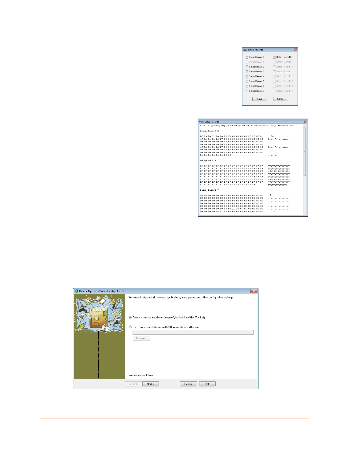
2. Click File > Save Setup Records… in the DeviceInstaller menu
bar. A dialog box with setup record choices appears.
3. Check the setup records you wish to save and click Save. A
browser window appears.
4. Browse to your save location and save your configuration file.
To view saved configuration information
1. Select your XPress device server through
DeviceInstaller (see Accessing the XPress
Device Server Using DeviceInstaller).
2. Click View > Setup Record File in the
DeviceInstaller menu bar.
3. Double-click to select the desired setup record
file.
4: Using DeviceInstaller
4. A View Setup Records window opens showing
contents of the configuration file.
Updating Configuration
Device configuration information can be saved in a file and later used to update the configuration
of other devices.
To update the configuration of a device from a saved file
1. Select your XPress device server through DeviceInstaller (see Accessing the XPress Device
Server Using DeviceInstaller).
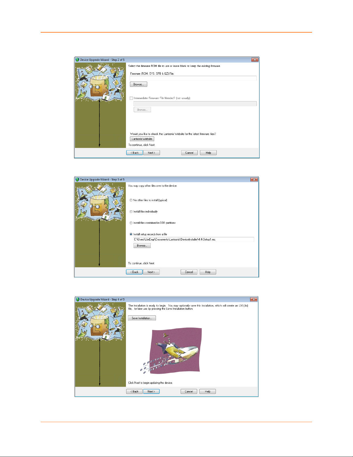
2. Click Device > Upgrade in the DeviceInstaller menu bar. Step 1 of 5 of the Device Upgrade
Wizard appears.
3. Check Create a custom installation by specifying individual files (Typical) and click Next
to advance to Step 2 of 5.
XPress™ DR Industrial Device Server User Guide 25
Page 26
4: Using DeviceInstaller
4. To continue without installing a new firmware file, just click Next. To install new firmware,
click Browse to browse to the firmware file and click Next to advance to Step 3 of 5.
5. Check Install setup records from a file, click Browse to browse to and select desired setup
record file, and click Next to advance to Step 4 of 5.
6. Click Save Installation, browse to and save to a desired save location, and click Next to
advance to Step 5 of 5.
XPress™ DR Industrial Device Server User Guide 26
Page 27
4: Using DeviceInstaller
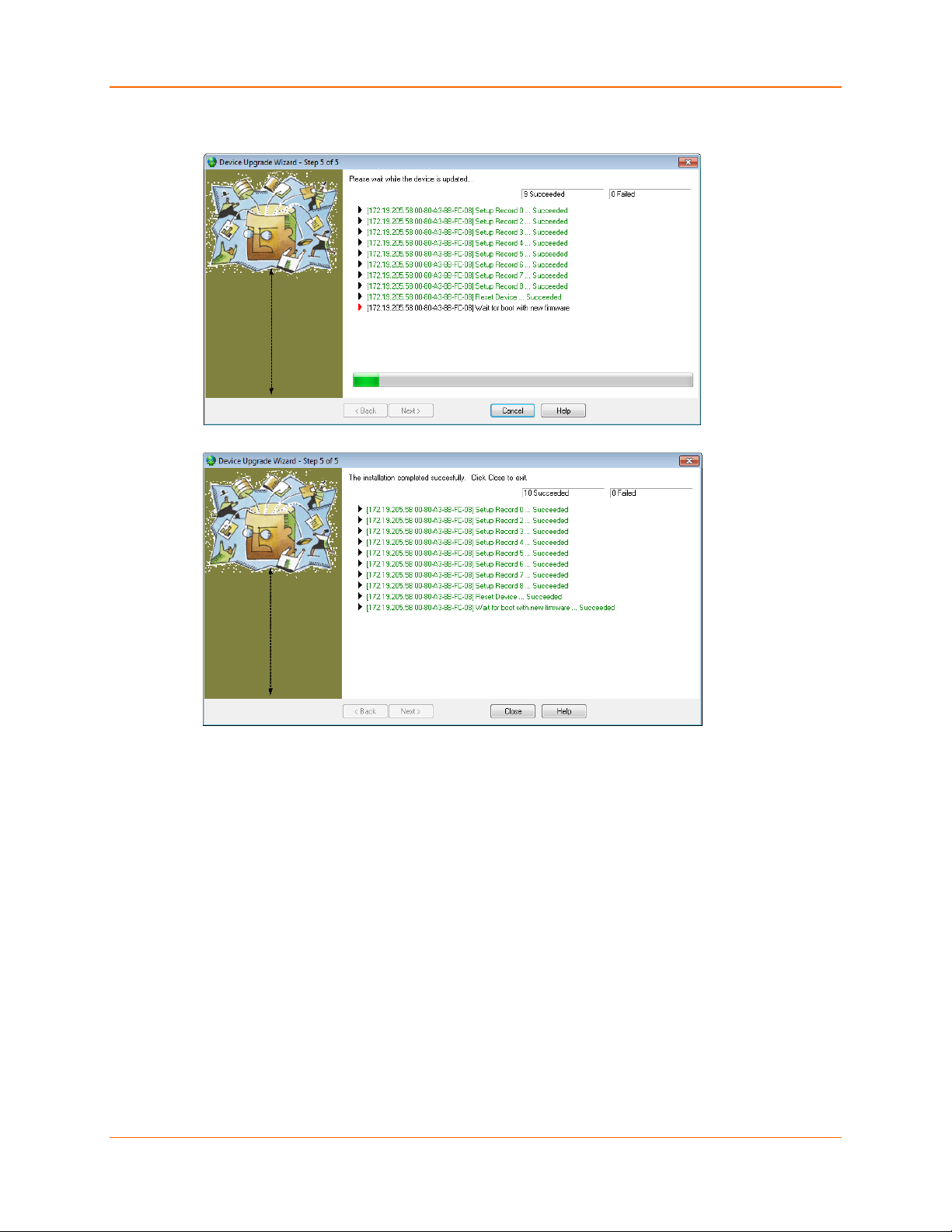
7. Click Next to upgrade your device (or Cancel to cancel.) Status of your device update will
appear in the Device Upgrade Wizard with a confirmation appearing once the unit is updated.
8. Click Close to exit the Device Upgrade Wizard.
XPress™ DR Industrial Device Server User Guide 27
Page 28
5: Configuration Using Web Manager
5: Configuration Using Web Manager
You must configure the unit so it can communicate on a network with your serial device. For
example, you must set the way the unit will respond to serial and network traffic, how it will handle
serial packets, and when to start or close a connection.
The unit’s configuration is stored in nonvolatile memory and is retained without power. You can
change the configuration any time. The unit resets after configuration is changed and stored.
In this chapter, we describe how to configure the XPress device server using Web Manager,
Lantronix’s browser-based configuration tool. (For information on using Setup Mode, our
command line configuration interface, see Accessing the Setup Mode Window.
Note: The examples in this section show a typical device. Your device may have different
configuration options.
Web Manager Page
Note: The XPress DR-IAP may not have a web page or may use a different format web page.
You can start a web browser for configuration by opening your JAVA-enabled web browser and
entering the IP address or by clicking the Web Configuration button on the Device Management
window. There is initially no Web Manager password for your XPress device server as first
received from Lantronix. We recommend that you always use the enhanced password setting
and create a strong 16 character password. Using no password is very dangerous. See Security
Settings (Option 6) on page 58.
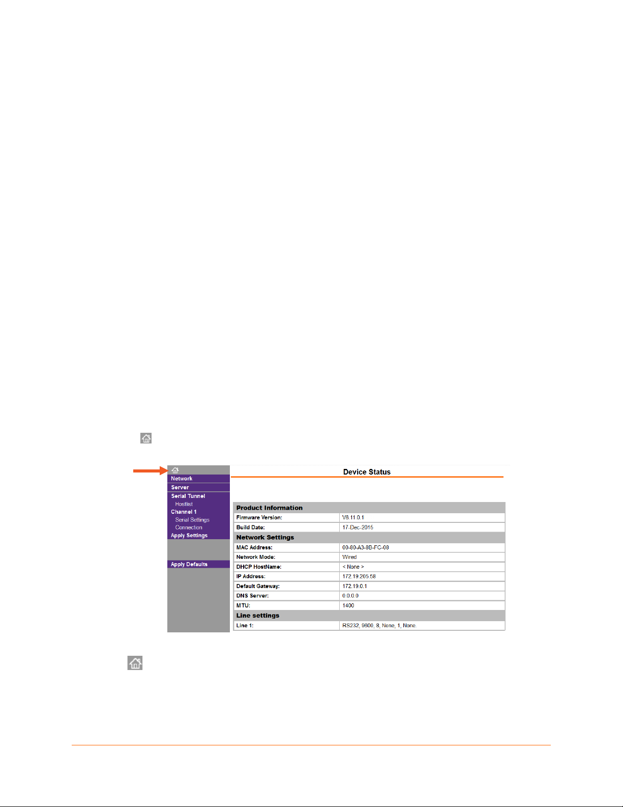
Device Status Home Page
You will reach the Device Status page upon logging into Web Manager. Clicking the
Home icon at the top of the Navigation bar will also bring you to the Device Status page.
Figure 5-1 Device Status Home Page
Navigate to content organized by links on the Navigation bar to the left:
(Device Status Home Page)
Network
Server
Serial Tunnel -- Hostlist
Channel 1 -- Serial Settings
Channel 1 – Connection
XPress™ DR Industrial Device Server User Guide 28
Page 29
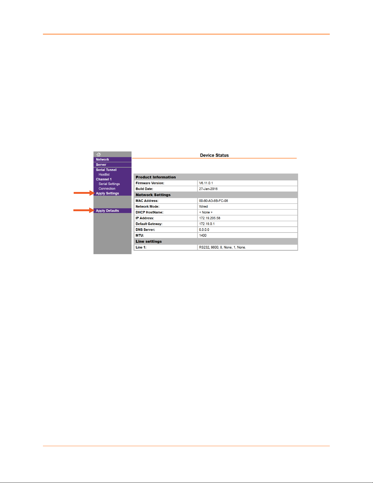
5: Configuration Using Web Manager
Apply Settings
1. To save and apply the configuration changes to the device server, click Apply Settings.
Note: Clicking OK on each page does not change the configuration on the device. Clicking the
OK button tells the XPress DR device server what changes to use; the Apply Settings button
makes the changes permanent and reboots the XPress DR unit.
Apply Defaults
1. Click Apply Defaults to set the device server back to the default settings.
2. Click Yes to set factory settings, or click No to cancel.
Figure 5-2 Apply Settings and Apply Defaults
XPress™ DR Industrial Device Server User Guide 29
Page 30
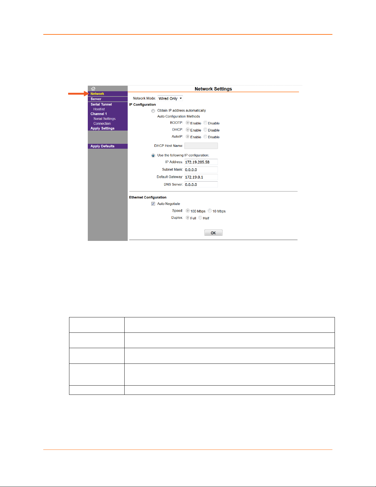
Network Configuration
The unit’s network values display when you select Network in the Navigation bar. The following
sections describe the configurable parameters on the Network Settings page.
5: Configuration Using Web Manager
Figure 5-3 Network Settings
Automatic IP Address Configuration
An IP address can be assigned automatically. You then enter related network settings.
To assign an IP address automatically:
1. In the Navigation bar, click Network.
2. Select Obtain IP address automatically.
3. Update the following:
Network Mode For the XPress device server, Wired Only is the only choice. It enables the
Ethernet network connectivity.
BOOTP Select Enable to permit the Bootstrap Protocol (BOOTP) server to assign the IP
address from a pool of addresses automatically. Enable is the default.
DHCP Select Enable to permit the Dynamic Host Configuration Protocol (DHCP) to
assign a leased IP address to the XPress unit automatically. Enable is the default.
AutoIP Select Enable to permit the Automatic Private IP Addressing (AutoIP) to generate
an IP in the 169.254.x.x address range for the XPress unit automatically within the
a Class B subnet. Enable is the default.
DHCP Host Name
Note: Disabling BOOTP, DHCP, and AutoIP (all three checkboxes) is not advised as the only
available IP assignment method will then be ARP or serial port.
4. When you are finished, click the OK button.
Enter the name of the host on the network providing the IP address.
Click Apply Settings in the Navigation bar.
5.
XPress™ DR Industrial Device Server User Guide 30
Page 31

5: Configuration Using Web Manager
IP Address
A subnet mask defines the number of bits taken from the IP address that are assigned
Auto Negotiate
Static IP Address Configuration
You can manually assign an IP address to the unit and enter related network settings.
To assign an IP address manually:
1. In the Navigation bar, click Network.
2. Select Use the following IP configuration.
3. Update the following:
If DHCP is not used to assign IP addresses, enter it manually in decimal-dot notation.
The IP address must be set to a unique value in the network.
Subnet Mask
for the host part.
Default Gateway
DNS Server
The gateway address, or router, allows communication to other LAN segments. The
gateway address should be the IP address of the router connected to the same LAN
segment as the unit. The gateway address must be within the local network.
The DNS server allows the name of a remote machine to be resolved automatically.
Enter the IP address of the DNS server. If the device is DHCP enabled, the DHCP
server provides the DNS server IP address, which will override this configured value.
Note: This setting is applicable only in Manual Connection mode.
4. When you are finished, click the OK button.
5. Click Apply Settings in the Navigation bar.
Ethernet Configuration
You must specify the speed and direction of data transmission.
To specify how data will be transmitted:
1. In the Navigation bar, click Network.
2. Update the following:
With this option, the Ethernet port auto-negotiates the speed and duplex with the
hardware endpoint to which it is connected. This is the default.
If this option is not selected, complete the fields that become available:
Speed: The speed of data transmission. The default setting is 100 Mbps.
Duplex: The direction of data transmission. The default setting is Full.
3. When you are finished, click the OK button.
4. Click Apply Settings in the Navigation bar.
XPress™ DR Industrial Device Server User Guide 31
Page 32

Enhanced Password
Telnet/Web Manager
Retype Password
ARP Cache Timeout (secs)
Server Configuration
The unit’s server values display when you select Server in the Navigation bar. The following
sections describe the configurable parameters on the Server Settings page.
5: Configuration Using Web Manager
Figure 5-4 Server Settings
To configure the XPress device server settings:
1. In the Navigation bar,, click Server.
2. Update the following:
Server Configuration
Select whether to enable advanced password:
Note: We recommend that
you always enable the
enhanced password setting,
and create a strong 16
character password.
Password
Enable: selecting this option enables advanced password creation,
allowing you to create passwords up to 16 bytes in length.
Disable: selecting this option disables advanced password creation,
allowing you to create basic passwords up to 4 bytes in length.
Enter the password required for Telnet configuration and Web Manager
access. No password or entering a “blank” password entry will disable
default password protection.
Re-enter the password required for Telnet configuration and Web
Manager access.
Advanced
XPress™ DR Industrial Device Server User Guide 32
When the unit communicates with another device on the network, it adds
an entry into its ARP table. ARP Cache timeout defines the number of
seconds (1-600) before it refreshes this table.
Page 33

5: Configuration Using Web Manager
TCP Keepalive (secs)
Monitor Mode @ Bootup
HTTP Server Port
Config Server Port
MTU Size
TCP Re-transmission
TCP Keepalive time defines how many seconds the unit waits during an
inactive connection before checking its status. If the unit does not receive
a response, it drops that connection. Enter a value between 0 and 60
seconds. 0 disables keepalive. The default setting is 45.
Select Disable to disable entry into the monitor mode using the yyy or
xx1 key sequence at startup. This field prevents the unit from entering
monitor mode by interpreting the stream of characters that are received
during the device server's initialization at startup. The default setting is
Enable.
This option allows the configuration of the web server port number. The
valid range is 1-65535. The default setting is 80.
Not applicable for this product.
The Maximum Transmission Unit (MTU) is the largest physical packet
size a network can transmit for TCP and UDP. Enter between 512 and
1400 bytes. The default setting is 1400 bytes.
timeout (ms)
The desired TCP re-transmission timeout value. If the ACK is not
received for a packet sent from the XPress device server, then the unit
will retransmit the data. The valid range is 500-4000 msec. The default is
500.
3. When you are finished, click the OK button.
4. Click Apply Settings in the Navigation bar.
XPress™ DR Industrial Device Server User Guide 33
Page 34

Retry Counter
Retry Timeout
Host Address
Port
Serial Tunnel - Hostlist Configuration
The XPress device server scrolls through the host list until it connects to a device listed in the
host list table. After a successful connection, the unit stops trying to connect to any others. If this
connection fails, the unit continues to scroll through the table until the next successful connection.
The host list supports a minimum of 1 and a maximum of 12 entries. Each entry contains an IP
address and a port number.
Note: The host list is disabled for Manual and Modem Mode. The unit does not accept a
data connection from a remote device when the hostlist option is enabled.
To configure the host list:
1. In the Navigation bar, click Hostlist.
Figure 5-5 Hostlist Settings
5: Configuration Using Web Manager
2. Update the following:
Retry Settings
Host Information
Enter the value for the number of times the XPress device server should
attempt to retry connecting to the host list. The default setting is 3.
Enter the duration (in milliseconds) the XPress device server should
abandon attempting a connection to the host list. The default setting is 250.
Enter or modify the host’s IP address.
Enter the target port number.
3. When you are finished, click the OK button.
4. Click Apply Settings in the Navigation bar.
XPress™ DR Industrial Device Server User Guide 34
Page 35

Disable Serial Port
Protocol
Flow Control
Channel 1 - Serial Settings Configuration
The Channel 1 configuration defines how the serial ports respond to network and serial
communication.
Serial Settings
To configure the channel’s serial settings:
1. In the Navigation bar, click Serial Settings (organized under Channel 1) to display the Serial
Settings window.
Figure 5-6 Channel Serial Settings
5: Configuration Using Web Manager
5. Update the following:
Channel 1
Port Settings
When selected, disables communication through the serial port. The
serial port is enabled by default.
Note: This feature is not available on single port device servers, since it
can only be applied to channel 1.
From the drop-down menu, select the protocol type for the selected
channel. The default setting is RS232.
XPress™ DR Industrial Device Server User Guide 35
Flow control manages data flow between devices in a network to ensure
it is processed efficiently. Too much data arriving before a device is
prepared to manage it causes lost or retransmitted data. None is the
default.
Page 36

Baud Rate
Data Bits
Parity
Stop Bits
Enable Packing
Idle Gap Time
Match 2 Byte Sequence
Match Bytes
Send Frame Immediate
Send Trailing Bytes
With Active Connect
With Passive Connect
Pack Control
5: Configuration Using Web Manager
The unit and attached serial device, such as a modem, must agree on a
speed or baud rate to use for the serial connection. Valid baud rates are
300, 600, 1200, 2400, 4800, 9600, 19200, 38400, 57600, and 115200
baud. The default setting is 9600.
Indicates the number of bits in a transmitted data package. The default
setting is 8.
Checks for the parity bit. The default setting is None.
The stop bit follows the data and parity bits in serial communication. It
indicates the end of transmission. The default setting is 1.
Select to enable packing on the XPress device server.
Two firmware-selectable packing algorithms define how and when
packets are sent to the network.
The standard algorithm is optimized for applications in which the unit is
used in a local environment, allowing for very small delays for single
characters, while keeping the packet count low.
The alternate packing algorithm minimizes the packet count on the
network and is especially useful in applications in a routed Wide Area
Network (WAN). Adjusting parameters in this mode can economize the
network data stream.
Disabled by default.
Select the maximum time for inactivity. The default time is 12
milliseconds.
Use to indicate the end of a series of data to be sent as one group. The
sequence must occur sequentially to indicate end of the data collection to
the XPress device server. The default setting is No.
Use to indicate the end of a series of data to be sent as one group. Set
this value to 00 if specific functions are not needed.
After the detection of the byte sequence, indicates whether to send the
data frame or the entire buffer. Select Yes to send only the data frame.
The default setting is No.
Select the number of bytes to send after the end-of-sequence characters.
The default setting is None.
Flush Input Buffer (Serial to Network)
Select Yes to clear the input buffer with a connection that is initiated from
the device to the network. The default setting is No.
Select Yes to clear the input buffer with a connection initiated from the
network to the device. The default setting is No.
XPress™ DR Industrial Device Server User Guide 36
Page 37

At Time of Disconnect
With Active Connect
With Passive Connect
At Time of Disconnect
Select Yes to clear the input buffer when the network connection to or
from the device is disconnected. The default setting is No.
Flush Output Buffer (Network to Serial)
Select Yes to clear the output buffer with a connection that is initiated
from the device to the network. The default setting is No.
Select Yes to clear the output buffer with a connection initiated from the
network to the device. The default setting is No.
Select Yes to clear the output buffer when the network connection to or
from the device is disconnected. The default setting is No.
6. When you are finished, click the OK button.
7. Click Apply Settings in the Navigation bar.
Channel 1 – Connection Configuration
Connection Settings - TCP
5: Configuration Using Web Manager
To configure a channel’s TCP settings:
1. In the Navigation bar, click Connection (organized beneath Channel 1). The Connection
Settings window for the channel displays.
Figure 5-7 TCP Connection Settings
XPress™ DR Industrial Device Server User Guide 37
Page 38

Protocol
Accept Incoming
Password Required
Password
Modem Escape Sequence
Active Connect
Start Character
Modem Mode
Show IP Address After RING
Local Port
Auto increment for Local Port
2. Update the following:
Connect Protocol
From the drop-down menu, select TCP.
Connect Mode: Passive Connection
Select Yes to accept incoming connections. The default setting is Yes.
Determines whether a password is required for an incoming passive
connection. This field is not available when a password is set for Telnet
mode. The default setting is No.
If Password Required was set to Yes, enter the password for passive
connections.
5: Configuration Using Web Manager
Pass Through
Disable or enable the XPress device server’s ability to send the escape
sequence. The default is Yes (send the escape sequence).
Connect Mode: Active Connection
Select None (default) to disable Active Connect. Otherwise, indicate
the connection type from the drop-down list:
With Any Character: Attempts to connect when any character is
With Active Mdm Ctrl In: Accepts external connection requests
With Start Character: Attempts to connect when it receives a
Manual Connection: Attempts to connect when directed by a
Auto Start: Automatically connects to the remote IP address and
If Active Connect is set to With Start Character, enter the start
character in this field. The default setting is 0D.
Indicates the on-screen response type when in Modem Mode (if Modem
Mode is enabled). The default setting is None.
received from the serial port.
only when the Modem Control In input is asserted.
specific start character from the serial port. The default start
character is carriage return.
command string received from the serial port.
port after booting up.
Endpoint Configuration
for active connect
XPress™ DR Industrial Device Server User Guide 38
Indicates whether to display the remote IP address upon connection.
The default setting is Yes.
Enter the local port number.
Select to auto-increment the local port number for new outgoing
connections. The range of auto-incremented port numbers is 50,000 to
59,999 and loops back to the beginning when the maximum range is
reached. Disabled by default.
Page 39

Remote Port
Remote Host
Telnet Com Port Cntrl
Terminal Name
ort Cntrl
Connect Response
Use Hostlist
LED
On Mdm_Ctrl_In Drop
Hard Disconnect
Check EOT (Ctrl-D)
Inactivity Timeout
Common Options
5: Configuration Using Web Manager
Enter the remote port number.
Enter the IP address of the remote device.
This field is available for configuration only when Active Connect is set
to None. Select Enable to permit Telnet communication to the XPress
unit. The Telnet Com Port Cntrl feature is used in conjunction with the
Com Port Redirector (CPR) utility. (See the CPR online Help for details.)
This field is available for configuration only when Telnet Com P
is set to Enable.
Use the terminal name for the Telnet terminal type. Enter only one
name. When this option is enabled, the unit also reacts to the end of
record (EOR) and binary options, which can be used for applications
such as terminal emulation to IBM hosts.
A single character is transmitted to the serial port when there is a
change in connection state. The default setting is None.
If this option is set to Yes, the device server scrolls through the host list
until it connects to a device listed in the host list table. Once it connects,
the unit stops trying to connect to any others. If this connection fails, the
unit continues to scroll through the table until it connects to another IP in
the host list.
The host list is disabled for Manual Mode and for Modem Mode. The
unit will not accept a data connection from a remote device when the
host list option is enabled.
XPress™ DR Industrial Device Server User Guide 39
Select Blink for the status LEDs to blink upon connection or None for
no LED output. The default setting is Blink.
Disconnect Mode
Set to Yes for the network connection to or from the serial port to
disconnect (drop) when Modem Control In transitions from an asserted
state to not asserted state. The default setting is No.
When set to Yes, the TCP connection closes even if the remote site
does not acknowledge the disconnect request.
Select Yes to drop the connection when Ctrl-D or Hex 04 is detected.
Both Telnet Com Port Cntrl and Check EOT
(Ctrl+ D) must be enabled for Disconnect with EOT to function
properly. Ctrl+D is only detected going from the serial port to the
network. The default setting is No.
Use this parameter to set an inactivity timeout. The unit drops the
connection if there is no activity on the serial line before the set time
expires. Enter time in the format mm:ss, where m is the number of
minutes and s is the number of seconds. To disable the inactivity
timeout, enter 00:00.
Page 40

5: Configuration Using Web Manager
Protocol
Datagram Type
Accept Incoming
Local Port
Remote Port
Remote Host
3. When you are finished, click the OK button.
4. Click Apply Settings in the Navigation bar.
Connection Settings - UDP
To configure a channel’s UDP settings:
1. In the Navigation bar, click Connection (organized beneath Channel 1). The Connection
Settings window for the selected channel displays.
2. In the available fields, enter or modify the following information:
Figure 5-8 UDP Connection Settings
Connect Protocol
Datagram Mode
Endpoint Configuration
Select UDP from the drop-down menu.
Configures the remote IP or network broadcast address and the remote
port. Enter 01 for directed or broadcast UDP. The default setting is 00.
Select Yes to accept incoming UDP datagrams. The default setting is Yes.
Enter the local port number.
Enter the port number of the remote device.
Enter the IP address of the remote device.
XPress™ DR Industrial Device Server User Guide 40
Page 41

Use Broadcast
Device Address Table
Select to broadcast the UDP datagram. Datagrams of type 01 can be sent
as a broadcast by enabling this option. The default is not to broadcast.
Note: Datagrams are sent as subnet-directed broadcasts.
The table is enabled when Datagram Type is set to FD. Enter Dev Addr
values between 1 and 255 to identify units on the local network of device
servers.
Note: Lantronix Tech Support supports Datagram type 01. Datagram Type
FD is for OEM use.
3. When you are finished, click the OK button.
4. Click Apply Settings in the Navigation bar.
5: Configuration Using Web Manager
XPress™ DR Industrial Device Server User Guide 41
Page 42

6: Configuration via Telnet or Serial Port (Setup Mode)
6: Configuration via Telnet or Serial Port (Setup
Mode)
You must configure the unit so it can communicate on a network with your serial device. As an
alternative to using a web browser, as described in the previous chapter, you can use the
following procedures remotely or locally:
Use a Telnet connection to configure the unit over the network.
Use a terminal or terminal emulation program to access the serial port locally.
The series of prompts at which you enter configuration settings is called Setup Mode.
Note: Detailed information about other setup methods is available from your Lantronix Sales
Associate.
The unit’s configuration is stored in nonvolatile memory and is retained without power. You can
change the configuration at any time. The unit performs a reset after the configuration has been
changed and stored.
This chapter tells you how to access Setup Mode and the general procedure for using it. To
complete the configuration, continue with chapters 7: Setup Mode: Server Configuration, 8:
Channel Mode: Channel Configuration, and 9: Setup Mode: Advanced Settings.
Note: The menus in the configuration chapters show a typical device. Your device may have
different configuration options.
Accessing the Setup Mode Window
Telnet Connection
To configure the unit over the network, establish a Telnet connection to port 9999.
Note: If you use the Telnet to Device icon on the DeviceInstaller Device Management window
OR a serial port login to establish the connection, skip steps 1and 2.
1. From the Windows Start menu, click Run and type the following command, where x.x.x.x is
the IP address and 9999 is the unit’s fixed network configuration port number.
telnet x.x.x.x 9999
Note: Be sure to include a space between the IP address and 9999.
2. Click OK.
3. The Lantronix Universal Device Server window displays.
*** Lantronix XPressDR-IAP Device Server ***
MAC address 0080A38BFC08
Software version V6.11.0.1 (160127)
Press Enter for Setup Mode
4. To enter the Setup Mode, you must press Enter within 5 seconds. The configuration
settings will appear. See Figure 6-1 Setup Mode Window.
Note: The following line appears only with a Telnet connection.
XPress™ DR Industrial Device Server User Guide 42
Page 43

6: Configuration via Telnet or Serial Port (Setup Mode)
Model: Device Server Plus+! (Firmware Code:EA)
5. Select an option on the menu by entering the number of the option in the Your choice ? field
and pressing Enter.
6. To enter a value for a parameter, type the value and press Enter, or to confirm a current
value, just press Enter.
7. When you are finished, save the new configurations (option 9). The unit will reboot.
Note: The Firmware Code AQ represents Standard Tunneling firmware.
Figure 6-1 Setup Mode Window (Standard Tunneling)
*** basic parameters
Hardware: Ethernet TPI
IP addr 172.19.205.58, gateway 172.19.0.1
DNS Server not set
DHCP FQDN option: Disabled
*** Security
SNMP is enabled
SNMP Community Name: public
Telnet Setup is enabled
TFTP Download is enabled
Port 77FEh is enabled
77FEh Access Mode is Read & Write
Web Server is enabled
Web Setup is enabled
ECHO is disabled
Enhanced Password is disabled
*** Channel 1
Baudrate 9600, I/F Mode 4C, Flow 00
Port 10001
Connect Mode : C0
Send '+++' in Modem Mode enabled
Show IP addr after 'RING' enabled
Auto increment source port disabled
Remote IP Adr: --- none ---, Port 00000
Disconn Mode : 40 (Telnet Com Port Cntrl Enabled)
Flush Mode : 00
Terminal name:
*** Expert
TCP Keepalive : 45s
ARP cache timeout: 600s
Monitor Mode @ bootup : enabled
HTTP Port Number : 80
MTU Size: 1400
TCP Re-transmission timeout: 500 ms
Alternate MAC: disabled
Ethernet connection type: auto-negotiate
Change Setup:
0 Server
1 Channel 1
5 Expert
6 Security
XPress™ DR Industrial Device Server User Guide 43
Page 44

7 Defaults
8 Exit without save
9 Save and exit Your choice ?
Serial Port Connection
If you want to initially configure the unit through a serial connection, follow these steps:
1. Connect a console terminal or PC running a terminal emulation program to your unit's serial
port. The default serial port settings are 9600 baud, 8 bits, no parity, 1 stop bit, no flow
control.
2. To enter Setup Mode, cycle the unit's power (power off and back on). After power-up, the
self-test begins and the red Diagnostic LED starts blinking. You have one second to enter
three lowercase x characters (xxx).
Note: The easiest way to enter Setup Mode is to hold down the x key at the terminal (or
emulation) while powering up the unit.
3. At this point, the screen display is the same as when you use a Telnet connection. To
continue with a serial port login, go to Telnet Connection.
Exiting Setup Mode
There are two options through which to exit setup mode:
6: Configuration via Telnet or Serial Port (Setup Mode)
To save all changes and reboot the device, select option 9 Save and exit from the Change
Setup menu. All values are stored in nonvolatile memory.
To exit the configuration mode without saving any changes or rebooting, select option
8 Exit without save from the Change Setup menu.
XPress™ DR Industrial Device Server User Guide 44
Page 45

7: Setup Mode: Server Configuration
Options
Bit
Value
7: Setup Mode: Server Configuration
This chapter explains how to configure the server through Setup Mode. All current values are
displayed in parenthesis.
Server Configuration (Option 0)
These are the unit’s basic network parameters. The following parameters are displayed when you
select Server configuration.
IP Address : (172) .(019) .(205) .(058)
Set Gateway IP Address (Y) ?
Gateway IP addr (172) .(019) .(000) .(001)
Netmask: Number of Bits for Host Part (0=default) (0)
Set DNS Server IP addr (N) ?
Change Telnet/Web Manager password (N) ?
IP Address
If DHCP is not used to assign IP addresses, enter the IP address manually. The IP address must
be set to a unique value in the network. Enter each octet and press Enter between each section.
The current value displays in parentheses.
IP Address : (000) .(000) .(000) .(000) _
If DHCP is used, the third octet of the IP address sets the BootP/DHCP/AutoIP options. The
following table shows the bits you can manually configure to force the XPress DR device server
to disable AutoIP, DHCP, or BootP. To disable an option, set the appropriate bit.
Table 7-1 BootP/DHCP/AutoIP Options
AutoIP
DHCP
BootP
For example, if the third octet is 0.0.5.0, the AutoIP and BootP options are disabled; only DHCP is
enabled. (The value 5 results from adding the binary equivalents of 0 and 2.) This is the most
common setting when using DHCP.
0 1
1 2
2 4
Set Gateway IP Address
The gateway address, or router, allows communication to other LAN segments. The gateway
address should be the IP address of the router connected to the same LAN segment as the unit.
The gateway address must be within the local network. The default setting is N (No), meaning the
gateway address has not been set. To set the gateway address, type Y and enter the address.
Set Gateway IP Address (N) ? Y
Gateway IP addr (000) .(000) .(000) .(000)_
XPress™ DR Industrial Device Server User Guide 45
Page 46

7: Setup Mode: Server Configuration
Netmask: Number of Bits for Host Part
A netmask defines the number of bits taken from the IP address that are assigned for the host
section.
Netmask: Number of Bits for Host Part (0=default) (0) _
Note: Class A: 24 bits; Class B: 16 bits; Class C: 8 bits.
The unit prompts for the number of host bits to be entered, then calculates the netmask, which is
displayed in standard decimal-dot notation when the saved parameters are displayed (for
example, 255.255.255.0). The default setting is 0.
Table 7-2 Standard IP Network Netmasks
Network Class Host Bits Netmask
A 24 255.0.0.0
B 16 255.255.0.0
C 8 255.255.255.0
Table 7-3 Netmask Examples
Netmask Host Bits
255.255.255.252 2
255.255.255.248 3
255.255.255.240 4
255.255.255.224 5
255.255.255.192 6
255.255.255.128 7
255.255.255.0 8
255.255.254.0 9
255.255.252.0 10
255.255.248.0 11
... ...
255.128.0.0 23
255.0.0.0 24
Set DNS Server IP Address
The DNS server allows the name of a remote machine to be resolved automatically. The default
is N (No), indicating the DNS server address has not been set. To set the DNS server address,
type Y. At the prompt, enter the DNS server address. If the device is DHCP enabled, the DHCP
server provides the DNS server IP address, which will override this configured value.
Note: This setting is applicable only in Manual Connection mode.
Set DNS Server IP addr (N) ?
XPress™ DR Industrial Device Server User Guide 46
Page 47

7: Setup Mode: Server Configuration
Change Telnet/Web Configuration Password
Setting the Telnet configuration password prevents unauthorized access of the setup menu via a
Telnet connection to port 9999 or via Web pages.
Please protect your device from unauthorized access and follow the instructions below:
Always select Y to enable Telnet/Web Manager password
Enable the enhanced password setting and create a strong 16-character password. For details,
see Security Settings (Option 6) on page 58.
Note: We do not recommend that you only use the 4-character basic password as it does not
offer sufficient security. Using no passwod is very dangerous.
Change Telnet/Web Manager password (N) ?
DHCP Naming
If a DHCP server has automatically assigned the IP address and network settings, you can
discover the unit by using the DeviceInstaller network search feature or Monitor Mode (see
11: Monitor Mode).
Note: When you enter Monitor Mode from the serial port with network connection enabled and
issue the NC (Network Communication) command, you see the unit’s IP configuration.
There are three methods for assigning DHCP names to the unit.
Default DHCP Name: If you do not change the DHCP name, and you are using an IP of
0.0.0.0, then the DHCP name defaults to XX.XX.XX.XX (XXXXXX is the last 6 digits of the
MAC address shown on the label on the bottom/side of the unit). For example, if the MAC
address is 00-20-4A-12-34-56, then the default DHCP name is C123456.
Custom DHCP Name: You can create your own DHCP name. If you are using an IP address
of 0.0.0.0, then the last option in Server configuration is Change DHCP device name. This
option allows you to change the DHCP name to an alphanumeric name (LTX in our example).
Change DHCP device name (not set) ? (N) Y
Enter new DHCP device name : LTX
Numeric DHCP Name: You can change the DHCP name by specifying the last octet of the
IP address. When you use this method, the DHCP name is LTXYY where YY is what you
chose for the last octet of the IP address. If the IP address you specify is 0.0.0.12, then the
DHCP name is LTX12. This method only works with 2 digit numbers (01-99).
XPress™ DR Industrial Device Server User Guide 47
Page 48

8: Channel Mode: Channel Configuration
8: Channel Mode: Channel Configuration
This chapter explains how to configure the serial port.
Notes:
Current values display in parenthesis.
You must enter some values in hexadecimal notation.
(See 95.)
Channel 1 (Option 1)
Select Channel 1 (option 1) from the Change Setup menu to define how the serial port responds
to network and serial communications. The following sections describe the configurable
parameters within the Channel configuration menu.
Figure 8-1. Serial Port Settings
Baudrate (9600) ?
I/F Mode (4C) ?
Flow (00) ?
Port No (10001) ?
ConnectMode (C0) ?
Send '+++' in Modem Mode (Y) ?
Show IP addr after 'RING' (Y) ?
Auto increment source port (N) ?
Remote IP Address : (000) .(000) .(000) .(000)
Remote Port (0) ?
DisConnMode (40) ? (Telnet Com Port Cntrl Enabled)
FlushMode (00) ?
DisConnTime (00:00) ?:
SendChar 1 (00) ?
SendChar 2 (00) ?
Terminal name () ?
Using this option, define how the serial port will respond to network and serial communications.
Baudrate
The unit and attached serial device, such as a modem, must agree on a speed or baud rate to
use for the serial connection. Valid baud rates are 300, 600, 1200, 2400, 4800, 9600 (default),
19200, 38400, 57600, and 115200 bits per second.
Baudrate (9600) ? _
I/F (Interface) Mode
The Interface (I/F) Mode is a bit-coded byte that you enter in hexadecimal notation.
The following table displays available I/F Mode options:
I/F Mode (4C) ? _
Note: All bit positions in the table that are blank represent “don’t care” bits for that particular
option, which can be set to either a 0 or 1 value.
XPress™ DR Industrial Device Server User Guide 48
Page 49

8: Channel Mode: Channel Configuration
I/F Mode Option
7
6
5
4
3
2
1
0
(1)
(1)
(1)
Table 8-1 Interface Mode Options
RS-232C
RS-422/485
RS-485 2-wire
7 Bit 1 0
8 Bit 1 1
No Parity 0 0
Even Parity 1 1
Odd Parity 0 1
1 Stop bit 0 1
2 Stop bit 1 1
0 0
0 1
1 1
(1) The XPress DR requires you to choose the correct setting in the IF mode, and to also set the
front-panel switch for selection of RS-232/RS-485.
The following table demonstrates how to build some common Interface Mode settings:
Table 8-2 Common Interface Mode Settings
Common I/F Mode Setting Binary Hex
RS-232C, 8-bit, No Parity, 1 stop bit (1) 0100 1100 4C
RS-232C, 7-bit, Even Parity, 1 stop bit (1) 0111 1000 78
RS-485 2-Wire, 8-bit, No Parity, 1 stop bit (1) 0100 1111 4F
RS-422, 8-bit, Odd Parity, 1 stop bit (1) 0101 1101 5D
(1) The XPress DR requires you to choose the correct setting in the IF mode, and to also set the
front-panel switch for selection of RS-232/RS-485.
Flow
Flow control sets the local handshake method for stopping serial input/output.
Flow (00) ? _
Table 8-3 Flow Control Options
Flow Control Option Hex
No flow control 00
XON/XOFF flow control 01
Hardware handshake with RTS/CTS lines 02
XON/XOFF pass characters to host 05
XPress™ DR Industrial Device Server User Guide 49
Page 50

8: Channel Mode: Channel Configuration
(1)
Port Number
The port number functions as the TCP/UDP source port number for outgoing packets. Packets
sent to the unit with this port number are received to this channel. The port number selected is
the Incoming TCP/UDP port and Outgoing TCP/UDP source port. Port 0 is used when you want
the outgoing source port to change with each connection.
Port No (10001) ? _
Default setting for Port 1 is 10001. Range: 0-65535 except for the following reserved port
numbers:
Table 8-4 Port Numbers
Port Numbers Reserved for
1 – 1024 Reserved (well known ports)
9999 Telnet setup
14000-14009 Reserved
30718 Reserved (77FEh)
10000-10999
Recommended ports, should be used for DeviceComm Manager
(COM1-COM256) or direct socket connections
Warning: We recommend that you not use the reserved port numbers for this setting as
incorrect operation may result.
Use Port 0 for the outgoing local port to change with each connection. The port range is 50,00059,999. Each subsequent connection increments the number by 1 (it wraps back around to
50,000).
Only use this automatic port increment feature to initiate a connection using TCP. Set the port to
a non-zero value when the unit is in a passive mode or when using UDP instead of TCP.
Connect Mode
Connect Mode defines how the unit makes a connection, and how it reacts to incoming
connections over the network.
ConnectMode (C0) ? _
Enter Connect Mode options in hexadecimal notation. The default setting is C0.
Note: See Table 11-1 Binary to Hexadecimal Conversion Table. All bit positions in the table that
are blank represent “don’t care” bits for that particular option, which can be set to either a 0 or 1
value.
Table 8-5 Connect Mode Options
Connect Mode Option 7 6 5 4 3 2 1 0
Incoming Connection
Never accept incoming 0 0 0
Accept incoming with DTR
Accept unconditional 1 1 0
Response
Nothing (quiet) 0
0 1 0
XPress™ DR Industrial Device Server User Guide 50
Page 51

8: Channel Mode: Channel Configuration
(1)
Character response (C=conn, D=disconn,
N=unreachable)
Startup
No active startup 0 0 0 0
With any character 0 0 0 1
With active DTR
With CR (0x0D) only 0 0 1 1
Manual connection 0 1 0 0
Autostart 0 1 0 1
Datagram Type
Directed UDP 1 1 0 0
Modem Mode
Full Verbose 1 0 1 1 0
Without Echo 0 0 1 1 0
1-character Response 1 0 1 1 1
0 0 1 0
1
(1) Inactive. DTR is hardwired to +12VDC.
Manual Connection: When you use manual connection, you are not required to enter the entire
IP address if the IP is already configured as the remote IP address in the unit. For example, if the
remote IP address already configured in the unit is 129.1.2.3, then an example command string
would be C3/7. (This would connect to 129.1.2.3 and port 7.) You may also use a different ending
for the connection string. For example, C50.1/23 would connect you to 129.1.50.1 and port 23.
Table 8-6 Manual Connection Address Example
Command String Result if remote IP is 129.1.2.3 and remote port is 1234
C121.2.4.5/1 Complete override; connection is started with host 121.2.4.5, port 1
C5 Connect to 129.1.2.5, port 1234
Connect to 129.1.28.10, port 12
C0.0.0.0/0 Enters Monitor Mode.
C28.10/12
Cwww.lantronix.com/80 Tries to connect to the Lantronix web server if the
<hostname:domain> (www.lantronix.com) is configured in the DNS server
database.
Autostart (Automatic Connection): If you enable Autostart, the unit automatically connects to
the remote IP address and remote port specified when the firmware starts.
Hostlist: If you enable this option, the device server scrolls through the hostlist until it connects
to a device listed in the hostlist table. Once it connects, the unit stops trying to connect to any
others. If this connection fails, the unit continues to scroll through the table until it is able to
connect to another IP in the hostlist.
Hostlist supports a minimum of 1 and a maximum of 12 entries. Each entry contains the IP
address and the port number.
The hostlist is disabled for Manual and Modem Modes. The unit does not accept a data
connection from a remote device when the hostlist option is enabled.
Datagram Type: When selecting this option, you will be prompted for the Datagram type. Enter
01 for directed or broadcast UDP.
XPress™ DR Industrial Device Server User Guide 51
Page 52

8: Channel Mode: Channel Configuration
Modem (Emulation) Mode: In Modem Mode, the unit presents a modem interface to the
attached serial device. It accepts AT-style modem commands, and handles the modem signals
correctly.
Normally there is a modem connected to a local PC and a modem connected to a remote
machine. A user must dial from the local PC to the remote machine, accumulating phone charges
for each connection. Modem Mode allows you to replace modems with device servers, and to use
an Ethernet connection instead of a phone call, without having to change communications
applications and make potentially expensive phone calls.
To select Modem Mode, set the Connect Mode to C6 (no echo), D6 (echo with full verbose), or
D7 (echo with 1-character response).
Note: If the unit is in Modem Mode and the serial port is idle, the unit can still accept network
TCP connections to the serial port if Connect Mode is set to C6 (no echo), D6 (echo with full
verbose), or D7 (echo with 1-character response).
In Modem Mode, echo refers to the echo of all of the characters entered in command mode; it
does not mean to echo data that is transferred. Quiet Mode (no echo) refers to the modem not
sending an answer to the commands received (or displaying what was typed).
To disconnect a connection using Modem Mode commands:
There must be 1-second guardtime (no data traffic) before sending +++.
There must not be a break longer that 1 second between +s.
There must be another 1-second guardtime after the last + is sent.
The unit acknowledges with an OK to indicate that it is in command mode.
Enter ATH and press Enter. It is echoed if echo is enabled. ATH is acknowledged by another
OK.
Table 8-7 Modem Mode Commands
Modem Mode
Command
ATDTx.x.x.x,pppp or
ATDTx.x.x.x/pppp
ATDTx.x.x.x
ATD0.0.0.0
ATD
ATDx.x.x.x
ATH Hangs up the connection (Entered as +++ATH ).
ATS0=n
ATEn
Function
Makes a connection to an IP address (x.x.x.x) and a remote port number
(pppp).
Makes a connection to an IP address (x.x.x.x) and the remote port number
defined within the unit.
Forces the unit into monitor mode if a remote IP address and port number
are defined within the unit.
Forces the unit into monitor mode if a remote IP address and port number
are not defined within the unit.
Makes a connection to an IP address (x.x.x.x) and the remote port number
defined within the unit.
Enables or disables connections from the network going to the serial
port.
n=0 disables the ability to make a connection from the network to the serial
port.
n=1-9 enables the ability to make a connection from the network
to the serial port.
n>1-9 is invalid.
Enables or disables character echo and responses.
n=0 disables character echo and responses.
n=1 enables character echo and responses.
XPress™ DR Industrial Device Server User Guide 52
Page 53

8: Channel Mode: Channel Configuration
(6)
Enables 1-character response or full verbose.
ATVn
n=0 enables 1-character response.
n=1 enables full verbose.
Note: These AT commands are only recognized as single commands like ATE0 or ATV1;
compound commands such as ATE0V1 are not recognized. All other AT commands with Modem
Mode set to full verbose acknowledge with an OK, but no action is taken.
Send the Escape Sequence (+++) in Modem Mode
Send ‘+++’ in Modem Mode (Y) ? _
Disable or enable the XPress DR device server’s ability to send the escape sequence. The
default setting is Y (Yes) (send the escape sequence).
Show IP addr after 'RING'
Show IP addr after 'RING' (Y) ?
Disable or enable the XPress DR unit's ability to show the IP address after RING in Modem
Mode. The default is Y (Yes), to show the IP address.
Auto Increment Source Port
Auto increment source port (N) ? _
Y (Yes) auto increment the source port. The XPress DR increments the port number used with
each new connection.
Remote IP Address
This is the destination IP address used with an outgoing connection.
Remote IP Address : (000) .(000) .(000) .(000)
Remote Port
The remote TCP port number must be set for the unit to make outgoing connections. This
parameter defines the port number on the target host to which a connection is attempted.
Remote Port (0) ?
Note: To connect an ASCII terminal to a host using the unit for login purposes, use the remote
port number 23 (Internet standard port number for Telnet services).
DisConnMode
DTR is hardwired to +12VDC. The Disconnect with DTR drop option is inactive.
Note: See Table F-1 Binary to Hexadecimal Conversion Table.
DisConnMode (40) ? (Telnet Com Port Cntrl Enabled)
Table 8-8 Disconnect Mode Options
Disconnect Mode Option 7 6 5 4 3 2 1 0
Disconnect with DTR drop
Ignore DTR 0
Telnet mode and terminal type
(1)
setup
1
1
XPress™ DR Industrial Device Server User Guide 53
Page 54

8: Channel Mode: Channel Configuration
(2)
(4)
(5)
Channel (port) password
Hard disconnect
Disable hard disconnect 1
State LED off with connection
Disconnect with EOT (^D)
1. The XPress DR will send the "Terminal Type" upon an outgoing connection.
2. A password is required for a connection to the serial port from the network.
3. The TCP connection will close even if the remote site does not acknowledge the disconnection.
4. When there is a network connection to or from the serial port, the state LED will turn off instead of blink.
5. When Ctrl D or Hex 04 are detected, the connection is dropped. Both Telnet mode and Disconnect with
EOT must be enabled for Disconnect with EOT to function properly. Ctrl D will only be detected going
from the serial port to the network.
6. DTR hardwired to +12VDC. This option is disabled in the XPress DR.
(3)
0
1
1
1
Flush Mode (Buffer Flushing)
Using this parameter, you can control line handling and network buffers with connection startup
and disconnect. You can also select between two different packing algorithms.
FlushMode (00) ?
Note: See Table F-1 Binary to Hexadecimal Conversion Table.
Table 8-9 Flush Mode Options
Function 7 6 5 4 3 2 1 0
Input Buffer (Serial to Network)
Clear with a connection that is initiated from the
XPress DR to the network
Clear with a connection initiated from the network
to the XPress DR
Clear when the network connection to or from the
XPress DR is disconnected
Output Buffer (Network to Serial)
Clear with a connection that is initiated from the
XPress DR to the network
Clear with a connection initiated from the network
to the XPress DR
Clear when the network connection to or from the
XPress DR is disconnected
Alternate Packing Algorithm (Pack Control)
Enable 1
1
1
1
1
1
1
Pack Control
Two firmware-selectable packing algorithms define how and when packets are sent to the
network. The standard algorithm is optimized for applications in which the unit is used in a local
environment, allowing for very small delays for single characters while keeping the packet count
low. The alternate packing algorithm minimizes the packet count on the network and is especially
useful in applications in a routed Wide Area Network (WAN). Adjusting parameters in this mode
can economize the network data stream.
XPress™ DR Industrial Device Server User Guide 54
Page 55

8: Channel Mode: Channel Configuration
Pack control settings are enabled in Flush Mode. Set this value to 00 if specific functions are not
needed.
Note: See Table 11-1 Binary to Hexadecimal Conversion Table.
Table 8-10 Pack Control Options
Option 7 6 5 4 3 2 1 0
Idle Time
Force transmit: 12ms 0 0
Force transmit: 52ms 0 1
Force transmit: 250ms 1 0
Force transmit: 5sec 1 1
Trailing Characters
None 0 0
One 0 1
Two 1 0
Send Characters
2-Byte Send Character
Sequence
Send Immediately After
Send chars
1
1
Idle Time: Idle time to "Force transmit" defines how long the unit should wait before sending
accumulated characters. This wait period is between characters. If there is an idle period between
characters equal to the force transmit set, then the unit will package up the serial data currently in
the buffer and send it to the network.
Trailing Characters: In some applications, CRC, Checksum, or other trailing characters follow
the end-of-sequence character; this option helps to adapt frame transmission to the frame
boundary.
Send Characters: If 2-Byte Send Character Sequence is enabled, the unit interprets the
sendchars as a 2-byte sequence; if not set, they are interpreted independently.
If Send Immediately After Characters is not set, any characters already in the serial buffer are
included in the transmission after a "transmit" condition is found. If set, the unit sends immediately
after recognizing the transmit condition (sendchar or timeout).
Note: A transmission might occur if status information needs to be exchanged or an
acknowledgment needs to be sent.
DisConnTime (Inactivity Timeout)
Use this parameter to set an inactivity timeout. The connection is dropped if there is no activity on
the serial line before the set time expires. Enter time in the following format: mm:ss, where m is
the number of minutes and s is the number of seconds. To disable the inactivity timeout, enter
00:00.
DisConnTime (00:00) ? _
To disable the inactivity timeout, enter 00:00. Range is 0 (disabled) to 5999 seconds (99 minutes,
59 seconds). Default setting is 0.
XPress™ DR Industrial Device Server User Guide 55
Page 56

8: Channel Mode: Channel Configuration
Send Characters
You can enter up to two characters in hexadecimal representation in the parameters "sendchar."
If a character received on the serial line matches one of these characters, it is sent immediately,
along with any awaiting characters, to the TCP connection. This minimizes the response time for
specific protocol characters on the serial line (for example, ETX, EOT, etc.). Setting the first
sendchar to 00 disables the recognition of the characters. Alternatively, the two characters can be
interpreted as a sequence.
SendChar 1 (00) ? _
SendChar 2 (00) ? _
Telnet Terminal Type
This parameter appears only if the terminal type option is enabled in Disconnect Mode (see
DisConnMode above). If this option is enabled, you can use the terminal name for the Telnet
terminal type. Enter only one name.
Terminal name () ?
If the terminal type option is enabled, the unit also reacts to the EOR (end of record) and binary
options, which can be used for applications like terminal emulation to IBM hosts.
Channel (Port) Password
This parameter appears only if the channel (port) password option is enabled in Disconnect Mode
(see DisConnMode). If set, you can set a password on the serial port.
XPress™ DR Industrial Device Server User Guide 56
Page 57

9: Setup Mode: Advanced Settings
9: Setup Mode: Advanced Settings
Expert Settings (Option 5)
These parameters should only be changed if you are an expert and definitely know the
consequences the changes might have.
TCP Keepalive time in s (1s - 65s; 0s=disable): (45) ?
ARP Cache timeout in s (0s - 600s) : (600) ?
Disable Monitor Mode @ bootup (N) ?
HTTP Port Number : (80) ?
MTU Size (512 - 1400): (1400) ?
TCP Re-transmission Timeout (500 - 4000) (ms): (500) ?
Enable alternate MAC (N) ?
Ethernet connection type: (0)
TCP Keepalive time in s
This option allows you to change how many seconds the unit will wait during a silent connection
before attempting to see if the currently connected network device is still on the network. If the
unit then gets no response, it will drop that connection.
TCP Keepalive time in s (1s - 65s; 0s=disable): (45) ?
ARP Cache timeout in s
Whenever the unit communicates with another device on the network, it will add an entry into its
ARP table. The ARP Cache timeout option allows you to define how many seconds (1-600) the
unit will wait before timing out this table.
ARP Cache timeout in s (0s - 600s) : (600) ?
Disable Monitor Mode at Bootup
This option allows you to disable all entries into Monitor Mode during startup, except for the ‘xxx’
sequence. This prevents entry using yyy, zzz, xx1, and yy1 key sequences (only during the
bootup sequence). The default for Monitor Mode at bootup is N (No). (See 11: Monitor Mode.)
Disable Monitor Mode @ bootup (N) ? _
HTTP Port Number
This option allows the configuration of the web server port number. The valid range is 1-65535.
The default HTTP port number is 80.
HTTP Port Number : (80) ? _
MTU Size
The Maximum Transmission Unit (MTU) is the largest physical packet size a network can transmit
for TCP and UDP. Enter between 512 and 1400 bytes. The default setting is 1400 bytes.
MTU Size: (512 - 1400): (1400) ? _
XPress™ DR Industrial Device Server User Guide 57
Page 58

9: Setup Mode: Advanced Settings
TCP Re-Transmission Timeout
This feature allows the configuration of the desired TCP re-transmission timeout value. If the ACK
is not received for a packet sent from the XPress DR device, then the unit will retransmit the data.
The valid range is 500-4000 msec.
TCP Re-transmission Timeout (500 – 4000) (ms): (500) ? _
Enable alternate MAC
If necessary, enable the alternate MAC address (if specified in the OEM setup record). The
default setting is N (No).
Enable alternate MAC (N) ? _
Ethernet Connection Type
The XPress DR device server allows for the Ethernet speed and duplex to be manually
configured. Enter 0 for auto-negotiation (default). To select the speed and duplex, enter one of
the following: 2 (10Mbit/half duplex), 3 (10Mbit/full duplex), 4 (100Mbit/half duplex), or 5
(100Mbit/full duplex).
Ethernet connection type: (0) ? _
Security Settings (Option 6)
Note: You can change these settings via Telnet or serial connections only, not on the Web-
Manager. We recommend that you set security over the dedicated network or over the serial
setup. If you set parameters over the network (Telnet 9999), someone else could capture these
settings.
Disable SNMP (N) ?
SNMP Community Name (public):
Disable Telnet Setup (N) ?
Disable TFTP Firmware Update (N) ?
Disable Port 77FEh (N) ?
77FEh Access Mode (0=Read & Write, 1=Read Only): (0) ?
Disable Web Server (N) ?
Disable Web Setup (N) ?
Disable ECHO ports (Y) ?
Enable Enhanced Password (N) ?
Disable SNMP
This setting allows you to disable the SNMP protocol on the unit for security reasons.
Disable SNMP (N) ?
XPress™ DR Industrial Device Server User Guide 58
Page 59

9: Setup Mode: Advanced Settings
SNMP Community Name
This option allows you to change the SNMP Community Name on the unit. This allows for ease of
management, and possibly some security. If someone tries to violate security but doesn’t know
what community to connect to, that person will be unable to get the SNMP community information
from the unit. The name is a string of 1 to 13 characters plus a null-terminator (14 bytes total).
The default setting is public.
SNMP Community Name (public):
Disable Telnet Setup
This setting defaults to the N (No) option. The Y (Yes) option disables access to this
Configuration Menu by Telnet (port 9999). It only allows access via the Web pages and the serial
port of the unit.
Disable Telnet Setup (N) ?
Disable TFTP Firmware Upgrade
This setting defaults to the N (No) option. The Y (Yes) option disables the use of TFTP to perform
network firmware upgrades. With this option, firmware upgrades can be performed only by using
a *.hex file over the serial port of the unit. See Using the Hyperterminal.
Disable TFTP Firmware Update (N) ?
Disable Port 77FE (Hex)
Port 77FE is a setting that allows DeviceInstaller, Web Pages, and custom programs to configure
the unit remotely. You may wish to disable this capability for security purposes. For more
information about remote configuration, see the Lantronix Embedded Integration Kit User Guide
at the Lantronix Web site www.lantronix.com/downloads
Disable Port 77FEh (N) ?
The default setting is the N (No) option, which enables remote configuration. You can configure
the unit by using DeviceInstaller, Web pages, Telnet, or serial configuration. The Y (Yes) option
disables remote configuration and Web pages.
Note: The Yes option disables many of the GUI tools for configuring the device server, including
the embedded Web Page Configuration tool.
.
77FEh Access Mode
Configuring this setting is available if port 77FE is enabled. This option will not be listed if port
77FE is disabled.
Set 0 for Read & Write mode, and 1 for Read Only mode. Default value of this setting is ReadWrite(0).
If access mode is Read-only, then read operation can be done through port 77FE, if Read-Write
access is selected, then both read and write of data can be done through port 77FE.
77FEh Access Mode (0=Read & Write, 1=Read Only): (0) ? _
Disable Web Server
This setting defaults to the N (option). The Y (Yes) option disables the use of the Web Page
Configuration tool that is built into the unit.
Disable Web Server (N) ?
XPress™ DR Industrial Device Server User Guide 59
Page 60

Disable Web Setup
The Y (Yes) option disables configuration using the Web-Manager. This setting defaults to the N
(No) option.
Disable Web Setup (N) ? _
Disable ECHO Ports
Controls whether the serial port will echo characters it receives.
Disable ECHO ports (Y) ?
Enable Enhanced Password
The Enhanced Password setting allows you to set a password of up to 16 characters for
protecting Telnet and Web Page access. We recommend that you select the Y (Yes) option and
enable the enhanced password setting.
Avoid using either the 4 character basic password setting or no password at all as they are not
secure options.
Enable Enhanced Password (N) ?
Default Settings (Option 7)
9: Setup Mode: Advanced Settings
Select 7 to reset the unit’s Channel 1 and Enhanced Security to the factory default settings. The
server configurations (IP address information) remain unchanged.
Exit Configuration Mode (Option 8 or Option 9)
Select 8 to exit the configuration mode without saving any changes or rebooting. Select 9 to save
all changes and reboot the device. All values are stored in nonvolatile memory.
XPress™ DR Industrial Device Server User Guide 60
Page 61

10: Firmware Upgrades
Obtaining Firmware
The XPress DR-IAP was designed to allow loading of vendor specific protocol firmware. This
firmware takes the place of the Standard Tunnel Protocol. Vendor specific protocols and the
software tools needed to load them can be found at www.lantronix.com/downloads
You can obtain the most up-to-date protocol firmware and release notes for the unit from the
Lantronix Web site (www.lantronix.com) or by using anonymous FTP (ftp.lantronix.com
Once you load a vendor specific protocol, you must reference the user manual associated with
that protocol, since many of the setup and configuration dialogs will be changed. Some features,
such as web pages, may not be available with certain vendor protocols.
Note: If you change the protocol to a vendor specific protocol, you MUST reference the
associated protocol manual for setup and configuration information. The menu options shown in
this manual are for Standard Tunnel Protocol.
Reloading Firmware
.
).
There are several ways to update the unit's internal operational code (*.rom): via TFTP, via
another unit, or via the serial port. You can also update the unit's internal web interface (*.cob) via
tftp or deviceinstaller.
The firmware files can be found at www.lantronix.com/downloads
Program Files\DeviceInstaller\Firmware folder. Here is a list of typical names for those files.
Check the Lantronix web site for the latest versions and release notes.
Table 10-1 Protocol Firmware
Folder Name ROM File COB
DA –XPress\Standard Tunnel xpressdr_61101.rom xpressdr_webm_2008.cob
DA –XPress\IAP Tunnel aqea_61101.rom
DA –XPress\Modbus IAP amea_3401.rom na
and -are installed in the
xpressdr_IAP_webm_2008.co b
Using TFTP Graphical User Interface
To download new firmware from a computer:
1. Use a TFTP client to send a binary file to the unit (*.ROM to upgrade the unit 's internal
operational code and *.COB to upgrade its internal Web interface).
Note: TFTP requires the .ROM (binary) version of the unit's internal operational code.
2. Make sure the Put and Binary options at the top of the window are selected.
3. Enter the full path of the firmware file in the Source File field.
4. In the Destination File field, enter the current internal operational code or WEB5 for the
internal Web interface. (DA=XPress Family IAP)
5. In the Remote Host field, enter the IP address of the unit being upgraded.
6. Click the Put button to transfer the file to the unit.
XPress™ DR Industrial Device Server User Guide 61
Page 62

10: Firmware Upgrades
Figure 10-1 TFTP Dialog Box
The unit performs a power reset after the firmware has been loaded and stored.
Distributing Firmware to Another Unit
To distribute firmware to another unit over the network:
1. Enter the host unit's Monitor Mode (see Monitor Mode).
2. Send the firmware to the receiving unit using the SF command, where x.x.x.x is the receiving
unit's IP address: SF x.x.x.x
The receiving unit performs a power reset after the firmware has been loaded and stored.
Note: You can only update your unit 's internal Web interface using TFTP or DeviceInstaller.
Using HyperTerminal
The following procedure is for using the HyperTerminal software application. In some cases, the
HEX format file is available for download at www.lantronix.com/downloads
Before you can load firmware through the serial port you need to convert the ROM code to HEX
format. There is a DOS application, R2H.EXE that can be used to convert the ROM file to HEX
format. The R2H.EXE application is available at ftp://ftp.lantronix.com/pub.
Put R2H.EXE and the *.ROM file into the same directory on a PC then open a DOS Window to
that directory and type: C:\ R2H filename
This will create a filename.hex file that you can load via the serial port.
Note: Do not switch off the power supply during the update. A loss of power while
reprogramming will result in a corrupt program image and a nonfunctional unit.
To download firmware from a computer via the unit’s serial port:
1. Enter Monitor Mode via the serial port. (see Monitor Mode).
.
2. Download the firmware to the unit using the DL command.
3. Select Send Text File and select the *.HEX file to be downloaded. The downloaded file must
be the .HEX (ASCII) version.
XPress™ DR Industrial Device Server User Guide 62
Page 63

10: Firmware Upgrades
4. After the final record is received, the unit checks the integrity of the firmware image before
programming the new firmware in the flash ROM. The following message displays when the
firmware upgrade is complete.
*** NodeSet 2.0 ***
0>DL
02049 lines loaded.
Note: You can only update your unit 's internal Web interface using TFTP or DeviceInstaller.
XPress™ DR Industrial Device Server User Guide 63
Page 64

VS x.x.x.x
GC x.x.x.x
SC x.x.x.x
PI x.x.x.x
11: Monitor Mode
Monitor Mode is a command-line interface used for diagnostic purposes (see Table 11-1- Monitor
Mode Commands). There are two ways to enter Monitor Mode: locally via the serial port or
remotely via the network.
Entering Monitor Mode Via the Serial Port
To enter Monitor Mode locally:
1. Follow the same principles used in setting the serial configuration parameters. See Chapter
6: Configuration via Telnet or Serial Port (Setup Mode).
2. Enter Monitor Mode in one of two ways:
♦ Type zzz (or xxl) to enter Monitor Mode with network connections.
♦ Type yyy to enter Monitor Mode without network connections.
An 0> prompt indicates that you have successfully entered Monitor Mode.
Entering Monitor Mode Via the Network Port
To enter Monitor Mode using a Telnet connection:
11: Monitor Mode
1. First establish a Telnet session to the configuration port (9999). The following message
appears:
MAC address 0080A38BFC08
Software version V6.11.0.1 (160127) XPressDR
Press Enter for Setup Mode
An 0> prompt indicates that you have successfully entered Monitor Mode.
Monitor Mode Commands
The following commands are available in Monitor Mode. Many commands have an IP address as
an optional parameter (xxx.xxx.xxx.xxx). If the IP address is given, the command is applied to
another network device with that IP address. If no IP address is given, the command is executed
locally.
Note: All commands must be given in capital letters.
Table 11-1 Monitor Mode Commands
Command Command Name Function
Version Queries software header record (16 bytes) of unit with
IP address x.x.x.x.
Get Configuration Gets configuration of unit with IP address x.x.x.x as hex
records (120 bytes).
Send Configuration Sets configuration of unit with IP address x.x.x.x from
hex records.
Ping Pings unit with IP address x.x.x.x to check device
status.
XPress™ DR Industrial Device Server User Guide 64
Page 65

AT
TT
NC
RS
QU
G0, G1, ....,Ge,
Gf
S0, S1,...,Se,
Sf
R0, R1, ....,Rb,
Rc
W0, W1, ....,Wb,
Wc
GM
SS
SA
NS
co
VN
Command Command Name Function
ARP Table Shows the unit’s ARP table entries.
TCP Connection Table Shows all incoming and outgoing TCP connections.
Network Connection Shows the unit’s current IP address, gateway, subnet
mask, and DNS server.
Reset Resets the unit’s power.
Quit Exits diagnostics mode.
11: Monitor Mode
Get configuration from
memory page
Set configuration to
memory page
Get configuration from
memory page
Set configuration to
memory page
Get MAC address Shows the unit's 6-byte MAC address.
Set Security record Sets the Security record without the encryption key and
Scan Initiates a wireless scan if the wireless interface is
Network Status Reports the network interfaces’ statuses. Includes
Gets a memory page of configuration information from
the device for setup record 0 to15.
Sets a memory page of configuration information on the
device for setup record 0 to15.
Gets a memory page of configuration information from
the device for setup record 16 to28.
Sets a memory page of configuration information on the
device for setup record 16 to 28.
length parameters. The entire record must still be
written, but the encryption-specific bytes do not need to
be provided (they can be null since they are not
overwritten).
enabled. Reports any stations found, including BSSID,
SSID, and RSSI. If SA is followed by a string, the string
is used to filter SSIDs before reporting. If the BSS does
not broadcast its SSID, only the BSSID and RSSI are
returned.
potentially negotiated parameters like speed/duplex for
Ethernet or BSSID, encryption, authentication for
wireless interfaces.
XPress™ DR Industrial Device Server User Guide 65
Set IP address, host
bits, gateway, and
DNS server IP
Query full firmware
version
Example:
co 192.168.0.10 8 192.168.0.1 10001 192.168.1.10
with
192.168.0.10 = IP address of the XPress DR
8 = number of host bits
192.168.0.1 = gateway IP address
10001 = port number of the XPress DR
192.168.1.10 = IP address of the DNS Server
The XPress DR stores the setup and performs a reset.
It sends an X before the reset if the command was OK.
This command queries and displays full firmware
version in readable string format.
Responses to some of the commands are given in Intel Hex format (see The Intel Hex Format).
Note: You may be required to enter QU twice to exit monitor mode.
Page 66

11: Monitor Mode
Response
Meaning
0>
OK; no error
1>
No answer from remote device
2>
Cannot reach remote device or no answer
8>
Wrong parameter(s)
9>
Invalid command
Entering any of the commands listed above will generate one of the following command response
codes:
Table 11-2 Command Response Codes
XPress™ DR Industrial Device Server User Guide 66
Page 67

Customer
Application
Local
Serial
(COM)
Port
Serial Data
Redirector
PC
Remote
Serial Data
to/from
Attached
Device
Device
Server
Ethernet Network
12: Com Port Redirector
The Com Port Redirector allows any PC running the Microsoft® Windows® operating system to
use ports on a network server as if they were connected directly to the PC. The Redirector
creates a virtual COM port within Windows, which for most purposes acts just like the selected
serial port on the server. Whenever this virtual port is accessed, the redirector forms a network
connection to the server, and routes all data between the physical serial port on the server and
the virtual port within Windows. This allows a modem on a server to be shared by many PC
users, thus the name of "modem sharing" which is commonly used to describe this.
The Redirector support both IP and IPX. For IP, you must have IP installed and bound to your
network card, and a server which supports TCP socket connections to its serial ports. For IPX,
you must have IPX/SPX installed and bound to your network card, and the server must support
IPX/SPX connections to its serial ports.
12: Com Port Redirector
The Com Port Redirector software download and the Com Port Redirector Quick Start Guide are
available at www.lantronix.com/downloads
Note: Com Port Redirector is not suitable for use with Modbus bridge firmware.
.
XPress™ DR Industrial Device Server User Guide 67
Page 68

A: Troubleshooting & Technical Support
L (Green)
L
RXD (Yellow)
LED
Error
A: Troubleshooting & Technical Support
This chapter discusses how you can diagnose and fix errors quickly without having to contact a
dealer or Lantronix.
LEDs
The device contains the following LEDs:
Two Green (R for ready, L for link)
Three Yellow (A for active, serial transmit, and serial receive)
One Red (F for fault)
Figure A-1 Product Information label
Table A-1 XPress DR LED Functions
LED Meaning
R (Green) Ready (Solid=ready, blinking = error message, port busy)
ink (socket connection made) = Solid
A (Yellow) Activity (network) = Random Flashing
TXD (Yellow)
F (Red)
Transmitting serially = Flashes during transmit
Receiving serially = Flashes during receive
Fault in XPress DR communication
(read error) or XPress DR is in Configuration Mode
Simultaneously lit F (Red) and R (Green) LEDs mean something is wrong. If the F (Red) LED is
lit or blinking, count the number of times the R (Green) LED blinks between its pauses. Six
possible blink patterns, detailed in the following table, indicate which fault condition exists.
Table A-2 LED Error Indications
Steady F (Red) and
Blinking R (Green)
Blinking F (Red) and
blinking R (Green)
1 blink = EPROM checksum error
2 blinks = RAM error
3 blinks = Token Ring error
4 blinks = EEPROM checksum error
1 blink = Faulty network connection
2 blinks = No DHCP response
4 blinks = Setup Mode
XPress™ DR Industrial Device Server User Guide 68
Page 69

Problem/Message
Reason
Solution
and do not press Enter quickly, the
address may only include numbers
Problems and Error Messages
It helps to connect a terminal to the serial port while diagnosing an error to view summary
messages that may be displayed. When troubleshooting, always ensure that the physical
connections (power cable, network cable, and serial cable) are secure.
Note: Some unexplained errors might be caused by duplicate IP addresses on the network. Make
sure that your unit's IP address is unique.
Table A-3 Problems and Error Messages
A: Troubleshooting & Technical Support
When you issue the ARP –S
command in Windows, “The ARP
entry addition failed: 5" message
displays.
When you attempted to assign an
IP address to the device server via
the ARP method, “Press Enter to
go into Setup Mode” is displayed.
Now when you Telnet to the
device server, the connection fails.
When you Telnet to port 9999, the
message “Press Enter to go into
Setup Mode” displays. However,
nothing happens when you press
Enter, or your connection is
closed.
When you Telnet to port 1 to
assign an IP address to the device
server, the Telnet window does
not respond for a long time.
Your currently logged-in user does
not have the correct rights to use
this command on this PC.
When you Telnet into port 1 on the
device server, you are only
assigning a temporary IP address.
When you Telnet into port 9999
device server will reboot, causing
it to lose the IP address.
You did not press Enter quickly
enough. You only have 5 seconds
to press Enter before the
connection is closed.
You may have entered the
Ethernet address incorrectly with
the ARP command.
Have someone from your IT
department log you in with
sufficient rights.
Telnet back into Port 1. Wait for it
to fail, then Telnet to port 9999
again. Make sure you press Enter
quickly.
Telnet to port 9999 again, but
press Enter as soon as you see
the message “Press Enter to go
into Setup Mode.”
Confirm that the Ethernet address
that you entered with the ARP
command is correct. The Ethernet
0-9 and letters A-F. In Windows
and usually in Unix, the segments
of the Ethernet address are
separated by dashes. In some
forms of Unix, the Ethernet
address is segmented with colons.
XPress™ DR Industrial Device Server User Guide 69
The IP address you are trying to
assign is not on your logical
subnet.
The device server may not be
plugged into the network
properly.
Confirm that your PC has an IP
address and that it is in the same
logical subnet that you are trying
to assign to the device server.
Make sure that the Link LED is lit.
If the Link LED is not lit, then the
device server is not properly
plugged into the network.
Page 70

A: Troubleshooting & Technical Support
ty, 1 Stop Bit, No Flow Control.
You are not Telneting to port 9999.
If you get a response, then there is
to verify that Telnet is not disabled.
Firmware
Problem/Message Reason Solution
When you try to assign an IP with
DeviceInstaller, you get the
following message:
“No response from device!
Verify the IP, Hardware
address and Network Class.
Please try again.”
The cause is most likely one of the
following:
The Hardware address you
specified is incorrect.
The IP address you are trying to
assign is not a valid IP for your
logical subnet.
You did not choose the correct
subnet mask.
Double-check the parameters that
you specified. Tip: You cannot
assign an IP address to a device
server through a router.
No LEDs are lit. The unit or its power supply is
damaged.
The device server will not power
up properly, and the LEDs are
flashing.
The device server is not
communicating with the serial
device it is attached to.
When you try to enter the setup
mode on the device server via the
serial port, you get no response.
You can ping the device server,
but not Telnet to the device server
on port 9999.
Various Consult the LEDs section in the
The most likely reason is the
wrong serial settings were chosen.
The issue will most likely be
something covered in the previous
problem, or possibly you have
Caps Lock on.
There may be an IP address
conflict on your network
The Telnet configuration port
(9999) is disabled within the
device server security settings.
A network device, such as a
router, is blocking port 9999.
Change power supplies.
Introduction chapter or the Quick
Start for the LED flashing
sequence patterns. Call Lantronix
Technical Support if the blinking
pattern indicates a critical error.
The serial settings for the serial
device and the device server must
match. The default serial settings
for the device server are RS232,
9600 Baud, 8 Character Bits, No
Pari
Double-check everything in the
problem above. Confirm that Caps
Lock is not on.
Turn the device server off and
then issue the following
commands at the DOS prompt of
your computer: ARP -D X.X.X.X
(X.X.X.X is the IP of the device
server)
PING X.X.X.X (X.X.X.X is the IP of
the device server).
a duplicate IP address on the
network (the LEDs on the device
server should flash a sequence
that tells you this). If you do not
get a response, use the serial port
With DeviceInstaller you get the
“Wrong Password” error when you
try to upgrade the firmware.
XPress™ DR Industrial Device Server User Guide 70
You have chosen the incorrect
setting for the Existing Firmware
field.
Try upgrading the firmware again,
but make sure to use the correct
setting in the field of Existing
field.
Page 71

A: Troubleshooting & Technical Support
Problem/Message Reason Solution
The device server appears to be
set up correctly, but you are not
communicating with your device
attached to the device server
across the network.
If you are sure that the serial port
setting is correct, then you may
not be connecting to the correct
socket of the device server.
Check the cables and wiring.
You can check to see whether
there is a socket connection to or
from the device server by looking
at the Ready LED.
If the Ready LED is blinking
consistently then there is a good
socket connection.
If the Ready LED is solid green,
then the socket connection does
not exist. Use the Connect Mode
option C0 for making a connection
to the device server from the
network. Use Connect Mode
option C1 or C5 for a connection
to the network from the device
server. See the full list of Connect
Mode Options in the Binary to
Hexadecimal chapter.
When connecting to the WebManager within the device server,
the message “No Connection With
CoBox” displays.
Your computer is not able to
connect to port 30718 (77FEh) on
the device server.
Lantronix Technical Support
Lantronix offers many resources to support our customers and products at
www.lantronix.com/support
access the FTP site and search through tutorials. At this site you can also find FAQs, bulletins,
warranty information, extended support services and product documentation.
To contact technical support or sales, look up your local office at
www.lantronix.com/about/contact.html
information:
Your name, company name, address, and phone number
Lantronix product and model number
Lantronix MAC address
Firmware version and current configuration
Description of the problem
. For instance, you can ask a question, find firmware downloads,
Make sure that port 30718
(77FEh) is not blocked with any
router that you are using on the
network. Also make sure that port
77FEh is not disabled within the
Security settings of the device
server.
. When you report a problem, please provide the following
Status of the unit when the problem occurred (please try to include information on user and
network activity at the time of the problem).
When troubleshooting the following problems, make sure that the XPress DR is powered up and
the Link (L) LED is lit solid green. If the Link LED is not lit, then the physical network connection is
bad. Confirm that you are using a good network connection.
XPress™ DR Industrial Device Server User Guide 71
Page 72

B: Network Configuration Using UDP
Byte
Command
Parameters
Notes
03
Node Reset
2 bytes, software
These 2 bytes are used to prevent accidental
CoBox firmware: 33 51 [Hex], 3Q)
F6
Query for
Version
None
The device server responds with the F7 block
F7
Firmware
First 16 bytes of the
mac address.
The first 16 bytes of the firmware image
address.
F8
Query for Setup
Record
None
The device server responds with the F9 block
below.
F9
Configuration
120 byte setup
7)
n/a
FA
Set
120 byte setup
7)
The IP address (byte 0-3) will not be
FB
Configuration
None
This block is sent back to the host requesting a
command.
B: Network Configuration Using UDP
UDP Datagrams
The device server can also be configured or queried over the network using UDP datagrams. The
device server has a UDP listener set for port 30718 (77FE Hex). Responses from the device
server are returned to the source port of the UDP packet.
The first three bytes of the UDP data block should be set to zero. The fourth byte selects the
function as described in the following table:
Table B-1 UDP Configuration
Firmware
Information
Readback
Configuration
Change
Acknowledge
type
firmware image,
and 4 bytes device
information and
record (see Setup
Records on page E-
record (see Setup
Records on page E-
reset of the device server. (Value for standard
below.
contain the software type (offset 4,5) and
checksum (offset 14,15). The last two bytes of
the device information contain the mac
overridden using FA. See FD for this
functionality.
configuration change (FB). After sending out
this block, the device server resets and uses
the new configuration sent with the FA
XPress™ DR Industrial Device Server User Guide 72
Page 73

FC
Set IP Address
First 8 bytes must
address.
This block can be sent as a broadcast,
FD
Set
and IP Address
Same as FA, but
as well (bytes 0-3).
n/a
Byte Command Parameters Notes
B: Network Configuration Using UDP
be set to the string
IP-SETUP (Hex 49
50 2D 53 45 54 55
50).
Next 2 bytes have
to be set to 00.
Next 2 bytes must
contain the mac
address.
Next 4 bytes have
to be the new IP
Configuration
changes IP address
Configuring Multiple Devices
When configuring a number of device servers identically, it is useful to create a template setup
record. The setup record can then be sent to the “target” device servers from a “master” device
server via “cut and paste” or UDP (see Network Configuration Using UDP).
because the mac address is unique. It provides
one method to set the IP address of the device
server if is on the local network and the mac
address is known. Remember, broadcasts are
only ‘heard’ on the subnet on which they are
generated. No reply is sent by the device
server, which restarts using the new IP
address after the block is received.
Example (all in Hex):
49 50 2D 63 45 54 55 50 00 00 2A 12 81 00 01
02
IP address of the node with mac address 42-18
set to 129.0.1.2
Device servers use a 120-byte setup record in Intel Hex format. This format facilitates the transfer
of binary data using ASCII characters. See Setup Records and The Intel Hex Format for
information about setup records and converting them to Intel Hex format.
:20000010AC10C81D0000100000000000AC10010B4C0200001127000000000000C000000011
:200020100000000000000000000000000000000000000000000000000000000000000000B0
:200040104C0200001227000000000000C00000000000000000000000000000000000000049
:1800601000000000000000000000000000000000000000000000000078
:00000001FF
Acquiring a Valid Setup Record
There are a number of ways to acquire a valid setup record:
Copy the setup record of a properly configured device server via Monitor Mode (easiest
method).
Request the setup record of a properly configured device server via another device server on
the network.
Build the setup record in software.
From a host PC, request the setup record of a properly configured device server via UDP.
To copy the setup record of a properly configured device server:
1. Configure a “master” device server with the desired parameters.
Figure B-1 Sample Setup Record in Intel Hex Format
XPress™ DR Industrial Device Server User Guide 73
2. Enter Monitor Mode on the master device server (see 11: Monitor Mode).
Page 74

B: Network Configuration Using UDP
3. At the prompt, enter GC followed by a carriage return. The device server will respond with its
setup record in Intel Hex format.
4. Copy the setup record into a text file and save it for future use.
To request the setup record of a properly configured device server via another device server on
the network:
1. Make sure that both units are plugged onto the network properly.
2. Enter Monitor Mode (with network support enabled) on the unit that is not properly
configured. (see 11: Monitor Mode)
3. Issue the command GC x.x.x.x followed by a carriage return, where x.x.x.x is the IP address
of the properly configured device. The properly configured device will respond by sending its
setup record to the unit you are currently on. This configuration will be displayed in Intel HEX
format.
4. Copy that HEX string, and then issue the command SC. Now paste the copied string.
To build the setup record in software:
1. Create a 120-byte setup record.
2. Convert it to an Intel Hex record (see The Intel Hex Format).
3. Copy the setup record into a text file and save it for future use.
To request the setup record of a properly configured device server via UDP:
1. Configure a device server with the desired parameters and place it on the network.
2. From a host PC, send the F8 datagram to the device server (see Network Configuration
Using UDP). The device server responds with the F9 datagram, which includes its setup
record.
3. Send a previously saved setup record from a host PC via UDP.
Sending a Setup Record
There are also a number of ways to send a setup record to a device server:
Send a previously saved setup record via Monitor Mode (easiest method).
Send the setup record of a properly configured device server to another device server on the
network.
Send a previously saved setup record from a host PC via UDP.
To send a setup record via Monitor Mode:
1. Configure a “master” device server with the desired parameters and place it on the network.
2. Place another device server (the “target”) on the network.
3. Enter Monitor Mode (with network support enabled) on the master device server (see
11: Monitor Mode.)
4. At the prompt, enter SC, the IP address of the target, and a carriage return.
5. Send the setup record to the target device server.
XPress™ DR Industrial Device Server User Guide 74
Page 75

B: Network Configuration Using UDP
Data block program memory (firmware)
00
End record
01
Data block configuration memory
10
Note: For example, using HyperTerminal, copy the setup record and select “Paste to Host” to
send it to the device server. The device server reboots with the new configuration.
To send a previously saved setup record to a device server via UDP, from a host PC, send the
FA (or FD) datagram to the “target” device server (see Network Configuration Using UDP).
Note: The device server responds with the FB datagram. Refer to the table.
The Intel Hex Format
With this format, 8-bit binary data can be sent and received as ASCII text. The transmission is
blocked in records, and every record has its own checksum.
The record begins with a colon (:) and consists of a block length (2-character Hex), a 16-bit
address (4-character Hex), and a block type (2-character Hex). It is built by adding all binary 8-bit
values and taking the complement, so adding all byte values (including length, address, and type)
should yield zero.
Example:
00000001FF
End record, type 01, length 00, address 00 00, checksum FF.
01002000805F
Data record consisting of one byte (value 80 Hex) for address 0020 (32 decimal).
For communication with the node, the following block types are defined:
Table B-2 Block Types
Option Hex
To get and set the node configuration, 120 bytes should be exchanged at once in 32-Byte
records. The IP address in the record (bytes 0 to 3) will be ignored (unless the UDP FD command
is being used).
Calculating the Checksum
As mentioned in Table B-2 Block Types above, the last two characters of an Intel Hex setup
record represent a checksum of the data in the line. Since the checksum is a two-digit
hexadecimal value, it can represent a value from 0 to 255.
The checksum is calculated by summing the value of the data on the line and taking the two’s
complement of the sum.
Note: Do not include the leading colon or the checksum byte in the sum.
Example:
0300300002337A1E
Record length: 03 (3 bytes of data)
Address: 0030 (the 3 bytes will be stored at 0030, 0031, and 0032)
Record Type: 00 (normal data)
Data: 02, 33, 7A
Checksum: 1E
03 + 00 + 30 + 00+ 02 + 33 + 7A = E2
XPress™ DR Industrial Device Server User Guide 75
Page 76

Byte(s)
Function
00-03
IP address of the unit (x.x.x.x)
04
Reserved (0)
05
Flag BYTE
Bits 5-0: Reserved (0)
06
Number of host bits for subnetting; if 0, matching standard netmask for Class A, B, C
is used.
07
Reserved (0)
08-11
Telnet configuration password (0 if not used)
12-15
Gateway IP address (0,0,0,0 if not used)
16-63
48-byte Channel 1 parameters; parameter setup Channel 1 (see Table E-4: Channel
Parameters)
64-111
48-byte Channel 2 parameters; parameter setup Channel 2 (see Table E-4: Channel
Parameters))
112-119
Reserved (0)
The two’s complement of E2 is 1E. See Calculating the Two’s Complement below.
Calculating the Two’s Complement
The two’s complement of a number is the value that must be added to the number to reach a
Hexadecimal value of 100 (256 in decimal). In the example above, E2 + 1E = 100.
You can also calculate the two’s complement by subtracting the sum from 100. Using the
example above again, 100 - E2 = 1E. It may help to use a scientific calculator.
Setup Records
A setup record consists of 120 bytes. They are transmitted at once from and to the node. Unused
bytes should be initialized as 00. Table B-3 Setup Record Construction defines the structure of a
setup record:
B: Network Configuration Using UDP
Table B-3 Setup Record Construction
Bit 7: Reserved (0)
Bit 6: Set 1 for AUI, 0 for 10BASE-T (CoBox-Micro only)
XPress™ DR Industrial Device Server User Guide 76
Page 77

B: Network Configuration Using UDP
16
Interface Mode (see Table B-5 Interface Mode Options)
17
Line Speed
Bits 4-0: Baud Rate (see Table B-7 Baud Rate Settings)
18
Flow Control (see Table B-8 Flow Control Options)
19
Reserved
20-21
Own TCP port low-byte, high-byte (Intel)
22-23
Remote TCP port low byte, high-byte (Intel)
24-27
Remote IP address (low/high low/high)
28
Connect Mode (see Table B-9- Connect Mode Options)
29
Disconnect Mode (see Table B-10 Disconnect Mode Options)
30
Disconnect w/ inactivity time-out, minutes (00 if unused)
31
Disconnect w/ inactivity time-out, seconds (00 if unused)
32-33
Characters to trigger send immediately (sendchar)
34
Flush mode (see Table B-11 Flush Mode Options)
35
Pack Control (see Table B-12 Pack Control Options)
36-47
Reserved (0)
48-63
a) Terminal name for Telnet terminal type option (15 characters max), 0-
Set).
RS-232C
(1)
0 0 RS-422/485
(1)
0 1 RS-485 2-wire
(1)
1 1 7 Bit
1 0 8 Bit
1 1 No Parity
0 0 Even Parity
1 1 Odd Parity
0 1 1 Stop bit
0 1 2 Stop bits
1 1
Channel Parameters
Use the following table to select setup record parameters for Channels 1:
Table B-4 Channel Parameters
Byte(s)
(Channel 1)
Function
Bits 7-5: Reserved
terminated. If set and Bit 6 in Disconnect Mode is set, Telnet connection will
be assumed.
b) Password for Passworded Socket Connection (Bit 4 in Disconnect Mode
Interface Mode
The Interface (I/F) Mode is a bit-coded byte entered in hexadecimal notation. Use the following
table to select Interface Mode settings:
Table B-5 Interface Mode Options
I/F Mode Option 7 6 5 4 3 2 1 0
(1) The XPress DR requires you to choose the correct setting in the IF mode, and to also set the
front-panel switch for selection of RS-232/RS-485.
The following table demonstrates how to build some common Interface Mode settings:
XPress™ DR Industrial Device Server User Guide 77
Page 78

B: Network Configuration Using UDP
Option
Binary
Hex
RS-232C, 8-bit, No Parity, 1 stop bit
(1)
0100 1100
4C
RS-232C, 7-bit, Even Parity, 1 stop bit
(1)
0111 1000
78
RS-485 2-Wire, 8-bit, No Parity, 1 stop bit
(1)
0100 1111
4F
RS-422, 8-bit, Odd Parity, 2 stop bits
(1)
1101 1101
DD
38400
00
19200
01
9600
02
4800
03
2400
04
1200
05
600
06
300
07
115200
08
57600
09
Option
Hex
No flow control
00
XON/XOFF flow control
01
Hardware handshake with RTS/CTS lines
02
XON/XOFF pass characters to host
05
Table B-6 Common Interface Mode Settings
(1) The XPress DR requires you to choose the correct setting in the IF mode, and to also set the
front-panel switch for selection of RS-232/RS-485.
Note: See Table 11-1 Binary to Hexadecimal Conversion Table.
Baud Rate
The device server and attached serial device must agree on a speed or baud rate to use for the
serial connection. Use the following table to select Baud Rate settings:
Table B-7 Baud Rate Settings
Speed (bps) Hex
Flow Control
Flow control sets the local handshaking method for stopping serial input/output. Generally, flow
control is not required if the connection is used to pass a blocked protocol with block sizes less
than 1k (ACK/NAK) and/or speeds of 19200 or less. Use the following table to select Flow Control
options:
Table B-8 Flow Control Options
XPress™ DR Industrial Device Server User Guide 78
Page 79

B: Network Configuration Using UDP
(1)
(1)
(6)
(1)
(2)
Connect Mode
Connect Mode defines how the device server makes a connection, and how it reacts to incoming
connections over the network. Use the following table to select Connect Mode options:
Table B-9 Connect Mode Options
Connect Mode Option 7 6 5 4 3 2 1 0
Incoming Connection
Never accept incoming 0 0 0
Accept incoming with DTR
Accept unconditional 1 1 0
Response
Nothing (quiet) 0
Character response (C=conn, D=disconn,
N=unreachable)
Startup
No active startup 0 0 0 0
With any character 0 0 0 1
With active DTR
With CR (0x0D) only 0 0 1 1
Manual connection 0 1 0 0
Autostart 0 1 0 1
Datagram Type
Directed UDP 1 1 0 0
Modem Mode
Full Verbose 1 0 1 1 0
Without Echo 0 0 1 1 0
1-character Response 1 0 1 1 1
0 0 1 0
0 1 0
1
(1) Inactive. DTR is hardwired to +12VDC.
Note: See Table 11-1 Binary to Hexadecimal Conversion Table.
Disconnect Mode
In Disconnect Mode, DTR drop either drops the connection or is ignored. Use the following table
to select Disconnect Mode Options:
Table B-10 Disconnect Mode Options
Disconnect Mode Option 7 6 5 4 3 2 1 0
Disconnect with DTR drop
Ignore DTR 0
Telnet mode and terminal type setup
Channel (port) password
XPress™ DR Industrial Device Server User Guide 79
1
1
1
Page 80

B: Network Configuration Using UDP
(3)
(4)
(5)
Disconnect Mode Option 7 6 5 4 3 2 1 0
Hard disconnect
Disable hard disconnect 1
State LED off with connection
Disconnect with EOT (^D)
1. The XPress DR will send the "Terminal Type" upon an outgoing connection.
2. A password is required for a connection to the serial port from the network.
3. The TCP connection will close even if the remote site does not acknowledge the disconnection.
4. When there is a network connection to or from the serial port, the state LED will turn off instead of blink.
5. When Ctrl D or Hex 04 are detected, the connection is dropped. Both Telnet mode and Disconnect with EOT
must be enabled for Disconnect with EOT to function properly. Ctrl D will only be detected going from the serial
port to the network.
6. DTR hardwired to +12VDC. This option is disabled in the XPress DR.
0
1
1
Note: See Table 11-1 Binary to Hexadecimal Conversion Table.
Flush Mode (Buffer Flushing)
Using this parameter, you can control line handling and network buffers with connection startup
and disconnect. You can also select between two different packing algorithms. Use the following
table to select Flush Mode options:
Table B-11 Flush Mode Options
Function 7 6 5 4 3 2 1 0
Input Buffer (Serial to Network)
Clear with a connection that is initiated from the
XPress DR to the network
Clear with a connection initiated from the network to
the XPress DR
Clear when the network connection to or from the
XPress DR is disconnected
Output Buffer (Network to Serial)
Clear with a connection that is initiated from the
XPress DR to the network
Clear with a connection initiated from the network to
the XPress DR
Clear when the network connection to or from the
XPress DR is disconnected
Alternate Packing Algorithm (Pack Control)
Enable 1
1
1
1
1
1
1
Note: See Table 11-1 Binary to Hexadecimal Conversion Table.
XPress™ DR Industrial Device Server User Guide 80
Page 81

Idle Time
Force transmit: 12ms
0
0
Force transmit: 52ms
0 1 Force transmit: 250ms
1 0 Force transmit: 5sec
1 1 Trailing Characters
None
0 0
One 0 1
Two 1 0
Send Characters
Sendchars Define 2-Byte Sequence
1 Send Immediately After Sendchars
1
Network Class
Network Portion of Address
Class A
First byte (2nd, 3rd, and 4th bytes are the host)
Class B
First 2 bytes (3rd and 4th bytes are the host)
Class C
First 3 bytes (4th byte is the host)
Pack Control
Alternate packing algorithm settings are enabled in Flush Mode. Use the following table to select
Pack Control options:
IP Addresses
B: Network Configuration Using UDP
Table B-12 Pack Control Options
Option 7 6 5 4 3 2 1 0
Each TCP/IP node on a network host has a unique IP address. This address provides the
information needed to forward packets on the local network and across multiple networks if
necessary.
IP addresses are specified as x.x.x.x, where each x is a number from 1 to 254; for example,
192.0.1.99. The device server must be assigned a unique IP address to use TCP/IP network
functionality.
IP addresses contain three pieces of information: the network, the subnet, and the host.
Network Portion
The network portion of the IP address is determined by the network type: Class A, B, or C.
Table B-13 Network Portion of IP Address
XPress™ DR Industrial Device Server User Guide 81
Page 82

B: Network Configuration Using UDP
A
0.0.0.0
127.0.0.0
1.0.0.0 to 126.0.0.0
B
128.0.0.0
191.255.0.0
128.1.0.0 to 191.254.0.0
C
192.0.0.0
223.255.255.0
192.0.1.0 to
223.255.254.0
D, E
224.0.0.0 to 255.255.255.254
255.255.255.255
None
In most network examples, the host portion of the address is set to zero.
Table B-14 Available IP Addresses
Class Reserved Available
Consider the IP address 36.1.3.4. This address is a Class A address; therefore, the network
portion of the address is 36.0.0.0 and the host portion is 1.3.4.
Subnet Portion
The subnet portion of the IP address represents which sub-network the address is from. Subnetworks are formed when an IP network is broken down into smaller networks using a subnet
mask.
A router is required between all networks and all sub-networks. Generally, hosts can send
packets directly only to hosts on their own sub-network. All packets destined for other subnets are
sent to a router on the local network.
Host Portion
The host portion of the IP address is a unique number assigned to identify the host.
Network Address
A host address with all host bits set to 0 addresses the network as a whole (for example, in
routing entries).
192.168.0.0
Broadcast Address
A host address with all host bits set to 1 is the broadcast address, meaning for “for every station.”
192.168.0.255
Network and broadcast addresses must not be used as a host address; for example, 192.168.0.0
identifies the entire network, and 192.168.0.255 identifies the broadcast address.
IP Subnet Mask
An IP subnet mask divides IP address differently than the standards defined by the classes A, B,
and C. An IP subnet mask defines the number of bits to be taken from the IP address as the
network or host sections. The device server prompts for the number of host bits to be entered and
then calculates the netmask, which is displayed in standard decimal-dot notation (for example,
255.255.255.0) when saved parameters are displayed.
XPress™ DR Industrial Device Server User Guide 82
Page 83

B: Network Configuration Using UDP
Network Class
Network Bits
Host Bits
Netmask
A 8 24
255.0.0.0
B
16
16
255.255.0.0
C
24 8 255.255.255.0
255.255.255.252
2
255.255.255.248
3
255.255.255.240
4
255.255.255.224
5
255.255.255.192
6
255.255.255.128
7
255.255.255.0
8
255.255.254.0
9
255.255.252.0
10
255.255.248.0
11
...
...
255.128.0.0
23
255.0.0.0
24
Table B-15 Standard IP Network Netmasks
Table B-16 Netmask Examples
Netmask Host Bits
Private IP Networks and the Internet
If your network is not and will not be connected to the Internet, you may use any IP address. If
your network is connected or will be connected to the Internet, or if you intend to operate the
device server on an intranet, you should use one of the reserved sub-networks. Consult your
network administrator with questions about IP address assignment.
Network RFCs
For more information about IP addresses, refer to the following documents, which can be located
on the World Wide Web using one of the following directories or indices:
RFC 950 Internet Standard Subnetting Procedure
RFC 1700 Assigned Numbers
RFC 1117 Internet Numbers
RFC 1597 Address Allocation for Private Networks.
XPress™ DR Industrial Device Server User Guide 83
Page 84

1
Not Connected
None
2
Hard-wired output
DTR
DTR Data Terminal Ready
3
To XPress DR
RXD or RX-
RS-232 RXD (Received Data)
RS-422/485: RX- (Received Data -)
4
From XPress DR
TXD or TX-
RS-232: TXD (Transmit Data)
RS-422/485: TX- (Transmit Data -)
5 GND
Ground
6
To XPress DR
CTS or RX+
RS-232: CTS (Clear to Send)
RS-422/485: RX+ (Received Data +)
7
From XPress DR
RTS or TX+
RS-232: RTS (Request to Send)
RS-422/485: TX+ (Transmit Data +)
8
Not Connected
None
C: Connections and Pinouts
Serial Interface
XPress DR has a single serial port that can be accessed by an RJ-45 connector or screw block
terminals. Both connectors support RS232 and RS485/422. By setting the switch located on the
face of the XPress DR, RS232 or RS485/422 can be selected.
Note: XPress DR is a single serial port device, meaning that only the RJ-45 or the screw
terminals can be used at a time. In the configuration menu, Channel 1 can refer to either the RJ45 or the screw terminal currently being used.
RJ-45 Serial Connector
The serial RJ-45 serial connector supports up to 115200 bits per second and has the following
signals.
Table C-1 Serial RJ45 Pinouts
Pin Direction Name Function
C: Connections and Pinouts
Note: Pin 2 (DTR) is hard wired to an RS232 positive voltage level and cannot be affected by
software control.
Note: For RS-485 2-wire functionality, pins 3 & 4 and 6 & 7 must be connected together.
XPress™ DR Industrial Device Server User Guide 84
Page 85

1
To XPress DR
RXD or RX-
RS-232: RXD (Received Data)
RS-422/485: RX- (Received Data -)
4
From XPress DR
TXD or TX-
RS-232: TXD (Transmit Data)
RS-422/485: TX- (Transmit Data -)
2
To XPress DR
CTS or RX+
RS-232: CTS (Clear to Send)
RS-422/485: RX+ (Received Data +)
3
From XPress DR
RTS or TX+
RS-232: RTS (Request to Send)
RS-422/485: TX+ (Transmit Data +)
8
Ground
GND
Ground
ETX+
Out
1
Ethernet Transmit Data +
ETX-
Out
2
Ethernet Transmit Data -
ERX+
In 3 Ethernet Receive Data +
ERX-
In 6 Ethernet Receive Data -
RXD CTS RTS TXD
Rx- Rx+ Tx+ Tx-
GND
1 2 3 4
8
Data+ Data-
GND
1 2 3
4
8
R
R = 120 Ohm, 1/8 W
RxD-
1 2
3 4
8
R
R = 120 Ohm, 1/8 W
RS-485 2-Wire RS-422/485 4-Wire
R
RxD+
TxD-TxD+ GND
RX- RX+ TX+ T X-
RX- RX+ TX+ TX- GND
Screw Terminal Serial Connectors
Table C-2 Serial Screw Terminal Pinouts
Pin Direction Name Function
Note: You can choose pin 5 or pin 8 as a ground (GND) pin.
Figure C-1 Serial Screw Terminal Pinouts
C: Connections and Pinouts
Note: For RS-485 2-wire functionality, pins 1 & 4 and 2 & 3 of the screw terminals must be
connected together.
Note: Termination resistors (R = 120 Ohm) are used to match impedance of a node to the
impedance of the transmission (TX) line. Termination resistors should be placed only at the
extreme ends of the data line, and no more than two terminations should be placed in any single
segment of a RS-485 network. The terminator resistors may not be needed for your application.
RJ-45 Ethernet Interface
XPress DR supports 10/100Mbit Ethernet through its RJ-45 (10BaseT/100BaseTX) connector.
Signal Name DIR PIN Primary Function
Table C-3 Ethernet Interface Signals
XPress™ DR Industrial Device Server User Guide 85
Page 86

Orange + White
Orange
Green + White
Blue
Blue + White
Green
Brown + White
Brown
View from
Connector End
The next drawing shows a typical RJ-45 connector. The color is not standard but very typical of
an Ethernet Patch cable. Pin 1 is located at the top of the connector (Orange + White). The view
is from the end of the connector.
Serial Interface Connections
The serial device can be RS-232 or RS-485/422 and the connections can be screw terminals or
RJ-45 connector. This section shows several practical methods for making the hardware
connections. The following diagrams show typical interface cables for the RS-232 Serial interface
and the Ethernet interface.
C: Connections and Pinouts
Figure C-2 RJ-45 Connector
9-Pin RS-232 to Serial RJ-45
The cable diagram below is for connecting a PC (com port) to the XPress DR serial RJ45 port.
You can use the serial RJ45 port to configure and test port settings prior to connection to your
automation device.
Figure C-3 RS-232 to Serial RJ-45 Connection
9-Pin RS-232 to Serial Screw Terminals
This connection assumes you are connecting a typical PC (COM1) to the XPress DR through the
serial screw terminals.
Figure C-4 RS-232 Configuration
XPress™ DR Industrial Device Server User Guide 86
Page 87

Front Panel Description
The following figure illustrates the screw block connector pinouts and other components of the
XPress DR. See Table C-4 Front Panel Components for explanations corresponding to the
circled numbers.
C: Connections and Pinouts
Figure C-5 Front Panel Layout
XPress™ DR Industrial Device Server User Guide 87
Page 88

Item
Component
Name
Purpose
1
RS-422/485:RX- (Received Data -)
2
Screw terminal
CTS or RX+
RS-232: CTS (Clear to Send)
RS-422/485: RX+ (Received Data +)
3
RS-422/485: TX+ (Transmit Data +)
4
Screw terminal
TXD or TX-
RS-232: TXD (Transmit Data)
RS-422/485: TX- (Transmit Data -)
6, 7
Screw terminal
NC
No connection
5, 8
Screw terminal
GND
Signal ground
9
Reset switch
RESET
Push to power reset and initialize
10
Configuration
(read error) or XPress DR is in Configuration Mode
11
LED (Green)
Ready
SOLID: Ready, Flashing: Error Message
12
LED (Yellow)
Activity
FLASHING: Network traffic
13
LED (Green)
Link
SOLID: XPress DR has good Ethernet link
14
Connector (RJ45)
Ethernet port
RJ45 connector for Ethernet 10BaseT
15
Connector (RJ45)
Serial port
RJ45 connector for RS-232,RS-422/485
16
LED (Yellow)
Serial TXD
FLASHING: Indicates transmission
from the serial port
17
to the serial port
18
Switch
Switch for
screw block
UP: Serial RS-232
DOWN: Serial RS-422/485
19
Screw terminal
DC + (or AC)
Operating power, DC positive or AC
20
Screw terminal
Ground
Earth ground
21
Screw terminal
DC – (or AC)
Operating power, DC negative or AC
22
Screw terminal
Ground
Earth ground
Table C-4 Front Panel Components
Screw terminal RXD or RX- RS-232: RXD (Received Data)
Screw terminal RTS or TX+ RS-232: RTS (Request to Send)
C: Connections and Pinouts
LED (Red) Fault or
SOLID: Fault in XPress DR communication
LED (Yellow) Serial RXD FLASHING: Indicates reception
Note: For RS-485 2-wire functionality, pins 1 & 4 and 2 & 3 of the screw terminals must be
connected together.
XPress™ DR Industrial Device Server User Guide 88
Page 89

19 20
21 22
GND
GND
9-30VDC
DC+
DC-
9-24VAC
Power Requirements
The XPress DR device server is normally powered by the same 12 VDC or 24 VDC supply that
powers other devices in your panel. Many AC-powered industrial controllers also supply 24 VAC
for use by field devices. The XPress DR is not shipped with a separate power supply, but any
power supply with a Limited Power Source (LPS) between 9-30 VDC or 9-24 VAC can be used.
The unit requires a maximum of 3 Watts.
Reset Switch
The unit has a reset switch located on the front panel, above the red LED.
C: Connections and Pinouts
Figure C-6 Power Requirements
Figure C-7 Reset Switch
RS-232/RS-485 Switch
This switch controls the type of serial interface used by the serial RJ45 connector. Set this switch
for RS-232 (Up) or RS-485 (Down).
Figure C-8 RS-232/RS-485 Switch
Note: The serial port RS232/RS485 switch is a hardware function. Do not change the switch
while the device is operating.
XPress™ DR Industrial Device Server User Guide 89
Page 90

Category
Description
Note: The power supply must be a Limited Power Source (LPS).
D: Technical Specifications
Table D-1 Technical Specification
CPU, Memory DSTni-EX 48MHz clock, 256 KB RAM
Flash, EEPROM 512 KB flash, 1024Byte EEPROM
Serial Interface RJ45 connector for RS-232 or RS-422/485 interface
Screw Terminals for RS-232 or RS-422/485 interface
Baud Rate selectable from 300 to 115Kbps
Switch selectable RS-232C or RS-422/485 (screw terminals only)
Reset Front panel recessed push button.
Power Input 9-30 VDC, 9-24 VAC, 3 Watts Max, Screw Terminals
Dimensions 90 x 60 x 36mm, (3.54 x 2.36 x 1.41 in)
Weight 120g (4.3oz)
Temperature Operating range: 0° to +60°C (32° to 140°F)
Humidity 20% to 90% RH, non-condensing
Case High-Impact Plastic case designed for DIN Rail (35mm)
Protocols Supported ARP, UDP/IP, TCP/IP, Telnet, ICMP, SNMP, DHCP, BOOTP, TFTP, and
HTTP
Network Interface 10Base-T/100Base-TX Ethernet, RJ45 connector
Serial Line Formats Characters: 7 or 8 data bits
Stop bits: 1 or 2
Parity: odd, even, none
Modem Control DTR, DCD, CTS, RTS
Flow Control CTS/RTS (hardware), XON/XOFF (software)
None
Management Internal web server (Standard Tunneling only)
SNMP (read only)
Serial login
Telnet login
Software Utility DeviceInstaller, Windows based configuration software
LEDs Ready, Fault/Configuration, Activity, Link, Serial Transmit, Serial Receive
Compatibility Ethernet: Version 2.0/IEEE 802.3
Isolation Ethernet: 1500 Vrms, Serial: 2000 Vrms Galvanic
Agency Approvals UL and CSA Class I, Division 2 Hazardous Locations, TUV, FCC, CE,
RCM, VCCI
XPress™ DR Industrial Device Server User Guide 90
Page 91

E: Alternative Ways to Assign an IP Address
E: Alternative Ways to Assign an IP Address
Earlier chapters describe how to assign a static IP address using DeviceInstaller, Web Manager,
and Setup Mode (through a Telnet or serial connection). This section covers other methods for
assigning an IP address over the network.
DHCP
The unit ships with a default IP address of 0.0.0.0, which automatically enables DHCP.
Provided a DHCP server exists on the network, it will assign the unit an IP address, gateway
address, and subnet mask when the unit boots up. The XPress DR has acquired an IP address if
the red LED stops flashing and the green Status LED is on continuously. (If no DHCP server
exists, the unit responds with a diagnostic error: the red Diagnostic LED blinks continuously, and
the green Status LED blinks five times. This blinking only continues for about 15 seconds.)
You can use the Lantronix® DeviceInstaller™ software to search the network for the IP your unit
has been assigned by the DHCP server and add it to the managed list. See Add the Unit to the
Manage List later in this chapter.
Note: This DHCP address will not appear in the unit’s standard configuration screens. You can
determine your unit’s DHCP-assigned IP address from the DHCP server, or in Monitor Mode.
When you enter Monitor Mode from the serial port with network connection enabled and issue the
NC (Network Communication) command, you will see the unit’s IP configuration.
AutoIP
The unit ships with a default IP address of 0.0.0.0, which automatically enables Auto IP within the
unit. AutoIP is an alternative to DHCP that allows hosts to automatically obtain an IP address in
smaller networks that may not have a DHCP server. A range of IP addresses (from 169.254.0.1
to 169.254.255.254) has been explicitly reserved for AutoIP-enabled devices. The range of Auto
IP addresses is not to be used over the Internet.
If your unit cannot find a DHCP server, and you have not manually assigned an IP address to it,
the unit automatically selects an address from the AutoIP reserved range. Then, your unit sends
out a (ARP) request to other nodes on the same network to see whether the selected address is
being used.
If the selected address is not in use, then the unit uses it for local subnet communication.
If another device is using the selected IP address, the unit selects another address from the
AutoIP is not intended to replace DHCP. The unit will continue to look for a DHCP server on the
network. If a DHCP server is found, the unit will switch to the DHCP server-provided address and
reboot.
Note: If a DHCP server is found, but it denies the request for an IP address, the unit does not
attach to the network, but waits and retries.
AutoIP can be disabled by setting the unit’s IP address to 0.0.1.0. This setting enables DHCP but
disables AutoIP.
An IP address is a 32-bit value, divided into four octets of eight bits each. The standard
representation is four decimal numbers (in the range of 0..255) divided by dots.
AutoIP range and reboots itself. After reboot, the unit sends out another ARP request to see if
the selected address is in use, and so on.
XPress™ DR Industrial Device Server User Guide 91
Page 92

E: Alternative Ways to Assign an IP Address
192.2.1.123
This is called decimal-dot notation.
The IP address is divided in two parts: network and host. To support different needs, three
network classes have been defined. Depending on the network class, the last one, two or three
bytes define the host, while the remaining part defines the network. In the following explanations,
x stands for the host part of the IP address:
Class A Network
IP address 1.x.x.x to 127.x.x.x
Only 127 different networks of this class exist. These have a very large number of potential
connected devices (up to 16,777,216).
Example: 10.0.0.1, (network 10, host 0.0.1)
Class B Network
IP address 128.0.x.x to 191.255.xxx.xxx
These networks are used for large company networks. Every network can consist of up to 65,534
devices.
Example: 172.1.3.2 (network 172.1, host 3.2)
Class C Network
IP address 192.0.0.xxx to 223.255.255.xxx
These network addresses are most common and are often used in small companies. These
networks can consist of a maximum number of 254 hosts.
Example: 192.7.1.9 (network 192.7.1, host 9)
The remaining addresses 224.x.x.x - 239.x.x.x are defined as ”class D” and are used as multicast
addresses.
The addresses 240.x.x.x. - 254.x.x.x are defined as class E and are reserved addresses.
Network Address
The host address with all host bits set to 0 is used to address the network as a whole (in routing
entries, for example).
Broadcast Address
The address with the host part bits set to 1 is the broadcast address, meaning for every station.
Network and broadcast addresses must not be used as a host address (for example, 192.168.0.0
identifies the entire network and 192.168.0.255 identifies the broadcast address).
IP Netmask
The netmask is used to divide the IP address differently from the standard defined by classes A,
B, C. A netmask defines how many bits from the IP address are to be taken as the network
section and how many bits are to be taken as the host section. When the number of host bits is
entered, the XPress DR calculates the netmask. The netmask is displayed in standard decimaldot notation.
XPress™ DR Industrial Device Server User Guide 92
Page 93

E: Alternative Ways to Assign an IP Address
Class A 8 24
255.0.0.0
Class B
16
16
255.255.0.0
Class C
24
8
255.255.255.0
255.255.255.252
2
255.255.255.248
3
255.255.255.240
4
255.255.255.224
5
255.255.255.192
6
255.255.255.128
7
255.255.255.0
8
255.255.254.0
9
255.255.252.0
10
255.255.248.0
11 . . . .
255.128.0.0
23
255.0.0.0
24
Network Bits Host Bits Netmask
Netmask Host bits
Private IP Networks and the Internet
If your network is not connected to the Internet, and there are no plans to make such a
connection, you may use any IP address you wish.
If your network is not connected to the Internet and you have plans to connect, or you are
connected to the Internet and want to operate your XPress DRs on an intranet, use one of the
subnetworks below. These network numbers have been reserved for such networks. If you have
any questions about IP assignment, consult your Network Administrator.
Class A 10.x.x.x
Class B 172.16.x.x
Class C 192.168.0.x
Network RFCs
For more information regarding IP addressing see the following documents. These can be located
on the World Wide Web using one of the directories or indices:
RFC 950 Internet Standard Subnetting Procedure
RFC 1700 Assigned Numbers
RFC 1117 Internet Numbers
RFC 1597 Address Allocation for Private Internets
XPress™ DR Industrial Device Server User Guide 93
Page 94

BOOTP
Similar to DHCP, but for smaller networks. Automatically assigns the IP address for a specific
duration of time.
ARP and Telnet
If the unit has no IP address, you can use Address Resolution Protocol (ARP) method from UNIX
and Windows-based systems to assign a temporary IP address.
To assign a temporary IP address:
1. On a UNIX or Windows-based host, create an entry in the host's ARP table using the
intended IP address and the hardware address of the unit (on the product label on the bottom
of the unit).
arp -s 191.12.3.77 00:20:4a:xx:xx:xx (Unix)
arp -s 191.12.3.77 00-20-4a-xx-xx-xx (Windows)
Note: For the ARP command to work on Windows operating system (OS), the ARP table on
the PC must have at least one IP address defined other than its own.
2. 1.1. If you are using Windows OS, type ARP -A at the DOS command prompt to verify that
there is at least one entry in the ARP table. If the local machine is the only entry, ping another
IP address on your network to build a new entry in the ARP table; the IP address must be a
host other than the machine on which you are working. Once there is at least one additional
entry in the ARP table, use the following command to ARP an IP address to the unit:
arp -s 191.12.3.77 00-20-4a-xx-xx-xx
E: Alternative Ways to Assign an IP Address
3. Open a Telnet connection to port 1. The connection fails quickly, but the unit temporarily
changes its IP address to the one designated in this step.
telnet 191.12.3.77 1
4. Open a Telnet connection to port 9999, and press Enter within five seconds to go into Setup
Mode. If you wait longer than five seconds, the unit reboots.
telnet 191.12.3.77 9999
Note: The IP address you just set is temporary and reverts to the default value when the
unit’s power is reset, unless you configure the unit with a static IP address and store the
changes permanently.
XPress™ DR Industrial Device Server User Guide 94
Page 95

0
0000 0 1
0001 1 2
0010 2 3
0011 3 4
0100 4 5
0101 5 6
0110 6 7
0111 7 8
1000 8 9
1001 9 10
1010 A 11
1011 B 12
1100 C 13
1101 D 14
1110 E 15
1111
F
F: Binary to Hex Conversion
Many of the device server’s configuration procedures require you to assemble a series of options
(represented as bits) into a complete command (represented as a byte). The resulting binary
value must be converted to a hexadecimal representation.
Converting Binary to Hexadecimal
The following are two simple ways to convert binary numbers to hexadecimals.
Conversion Table
Hexadecimal digits have values ranging from 0 to F, which are represented as 0-9, A (for 10), B
(for 11), etc. To convert a binary value (for example, 0010 0011) to a hexadecimal representation,
the upper and lower four bits are treated separately, resulting in a two-digit hexadecimal number
(in this case, 4C).
Use the following table to convert values from binary to hexadecimal.
Table F-1 Binary to Hexadecimal Conversion Table
Decimal Binary Hex
Scientific Calculator
Another simple way to convert binary to hexadecimals is to use a scientific calculator, such as the
one available on Windows’ operating systems. For example:
1. On the Windows’ Start menu, click ProgramsAccessoriesCalculator.
2. On the View menu, select Scientific. The scientific calculator displays.
3. Select Bin (Binary), and type the number to convert.
XPress™ DR Industrial Device Server User Guide 95
Page 96

Never
None (quiet)
No active startup
N/A
Never
None (quiet)
Any character
1
Never
None (quiet)
Active DTR
2
Never
None (quiet)
CR (0x0D)
3
Never
None (quiet)
Manual connection
4
Never
None (quiet)
Autostart
5
Never
None (quiet)
UDP C
Never
Character
No active startup
10
Never
Character
Any character
11
Never
Character
Active DTR
12
Never
Character
CR (0x0D)
13
Never
Character
Manual connection
14
Never
Character
Autostart
15
Never
Character
UDP 1C
With DTR
None (quiet)
No active startup
40
With DTR
None (quiet)
Any character
41
With DTR
None (quiet)
Active DTR
42
With DTR
None (quiet)
CR (0x0D)
43
With DTR
None (quiet)
Manual connection
44
With DTR
None (quiet)
Autostart
45
With DTR
None (quiet)
UDP
4C
With DTR
Character
No active startup
50
4. Click Hex. The hexadecimal value displays.
F: Binary to Hex Conversion
Connect Mode Options
Note: Character response codes are C=connect, D=disconnect, N=unreachable
Accept Incoming
Connections
Serial Response
Upon Connection
Table F-2 Connect Mode Options
Active Connection Startup Hostlist Hex
XPress™ DR Industrial Device Server User Guide 96
Page 97

With DTR
Character
Any character
51
With DTR
Character
Active DTR
52
With DTR
Character
CR (0x0D)
53
With DTR
Character
Manual connection
54
With DTR
Character
Autostart
55
With DTR
Character
UDP
N/A
Unconditionally
None (quiet)
No active startup
C0
Unconditionally
None (quiet)
Any character
C1
Unconditionally
None (quiet)
Active DTR
C2
Unconditionally
None (quiet)
CR (0x0D)
C3
Unconditionally
None (quiet)
Manual connection
C4
Unconditionally
None (quiet)
Autostart
C5
Unconditionally
None (quiet)
UDP
CC
Unconditionally
Character
No active startup
D0
Unconditionally
Character
Any character
D1
Unconditionally
Character
Active DTR
D2
Unconditionally
Character
CR (0x0D)
D3
Unconditionally
Character
Manual connection
D4
Unconditionally
Character
Autostart
D5
Unconditionally
Character
UDP
DC
Never
None (quiet)
No active startup
Hostlist
N/A
Never
None (quiet)
Any character
Hostlist
21
Never
None (quiet)
Active DTR
Hostlist
22
Never
None (quiet)
CR (0x0D)
Hostlist
23
Never
None (quiet)
Manual connection
Hostlist
N/A
Never
None (quiet)
Autostart
Hostlist
25
Never
None (quiet)
UDP
Hostlist
Never
Character
No active startup
Hostlist
N/A
Never
Character
Any character
Hostlist
31
Never
Character
Active DTR
Hostlist
32
Never
Character
CR (0x0D)
Hostlist
33
Never
Character
Manual connection
Hostlist
N/A
Never
Character
Autostart
Hostlist
35
Never
Character
UDP
Hostlist
N/A
With DTR
None (quiet)
No active startup
Hostlist
N/A
With DTR
None (quiet)
Any character
Hostlist
61
With DTR
None (quiet)
Active DTR
Hostlist
62
With DTR
None (quiet)
CR (0x0D)
Hostlist
63
With DTR
None (quiet)
Manual connection
Hostlist
N/A
With DTR
None (quiet)
Autostart
Hostlist
65
With DTR
None (quiet)
UDP
Hostlist
N/A
With DTR
Character
No active startup
Hostlist
N/A
With DTR
Character
Any character
Hostlist
71
With DTR
Character
Active DTR
Hostlist
72
With DTR
Character
CR (0x0D)
Hostlist
73
With DTR
Character
Manual connection
Hostlist
N/A
With DTR
Character
Autostart
Hostlist
75
With DTR
Character
UDP
Hostlist
N/A
Unconditionally
None (quiet)
No active startup
Hostlist
N/A
Unconditionally
None (quiet)
Any character
Hostlist
E1
Unconditionally
None (quiet)
Active DTR
Hostlist
E2
Unconditionally
None (quiet)
CR (0x0D)
Hostlist
E3
Unconditionally
None (quiet)
Manual connection
Hostlist
N/A
Accept Incoming
Connections
Serial Response
Upon Connection
F: Binary to Hex Conversion
Active Connection Startup Hostlist Hex
XPress™ DR Industrial Device Server User Guide 97
Page 98

F: Binary to Hex Conversion
Unconditionally
None (quiet)
Autostart
Hostlist
E5
Unconditionally
None (quiet)
UDP
Hostlist
N/A
Unconditionally
Character
No active startup
Hostlist
N/A
Unconditionally
Character
Any character
Hostlist
F1
Unconditionally
Character
Active DTR
Hostlist
F2
Unconditionally
Character
CR (0x0D)
Hostlist
F3
Unconditionally
Character
Manual connection
Hostlist
N/A
Unconditionally
Character
Autostart
Hostlist
F5
Unconditionally
Character
UDP
Hostlist
N/A
Never
Echo
16
Never
Without echo
6
Never
1-character response
7
With DTR
Echo
56
With DTR
Without echo
46
With DTR
1-character response
47
Unconditionally
Echo
D6
Unconditionally
Without echo
C6
Unconditionally
1-character response
C7
Enable
0
Enable
Enable
10 Enable
Enable
20
Enable
Enable
Enable
30 Enable
Enable
40 Enable
Enable
Enable
50 Enable
Enable
Enable
60 Enable
Enable
Enable
Enable
70
Enable
Enable
80
Enable
Enable
Enable
90
Enable
Enable
Enable
A0
Enable
Enable
Enable
Enable
B0
Enable
Enable
Enable
C0
Enable
Enable
Enable
Enable
D0
Accept Incoming
Connections
Serial Response
Upon Connection
Active Connection Startup Hostlist Hex
Note: The XPress DR DTR signal is hardwired to +12VDC. DTR options are inactive.
The following connect mode options are for when you use modem emulation:
Table F-3 Connect Mode Options for Modem Emulation
Accept Incoming
Connections
Disconnect Mode Options
Table F-4 Disconnect Mode Options
Disconnect
with DTR
Drop (Note)
Telnet
Mode and
Terminal
Type Setup
Channel
(port)
Password
Response Hex
Hard
Disconnect
State LED
Off with
Connection
Disconnect
with EOT
(^D)
Hex
XPress™ DR Industrial Device Server User Guide 98
Page 99

Type Setup
Enable
Enable
Enable
Enable
E0
Enable
Enable
Enable
Enable
Enable
F0
Enable
Enable
1
Enable
Enable
Enable
11 Enable
Enable
Enable
21
Enable
Enable
Enable
Enable
31 Enable
Enable
Enable
41 Enable
Enable
Enable
Enable
51 Enable
Enable
Enable
Enable
61 Enable
Enable
Enable
Enable
Enable
71
Enable
Enable
Enable
81
Enable
Enable
Enable
Enable
91
Enable
Enable
Enable
Enable
A1
Enable
Enable
Enable
Enable
Enable
B1
Enable
Enable
Enable
Enable
C1
Enable
Enable
Enable
Enable
Enable
D1
Enable
Enable
Enable
Enable
Enable
E1
Enable
Enable
Enable
Enable
Enable
Enable
F1
Disable
8
Enable
Disable
18
Disable
Enable
28
Enable
Disable
Enable
38 Enable
Disable
48 Enable
Enable
Disable
58 Enable
Disable
Enable
68 Enable
Enable
Disable
Enable
78
Enable
Disable
88
Enable
Enable
Disable
98
Enable
Disable
Enable
A8
Enable
Enable
Disable
Enable
B8
Enable
Enable
Disable
C8
Enable
Enable
Enable
Disable
D8
Enable
Enable
Disable
Enable
E8
Enable
Enable
Enable
Disable
Enable
F8
Disable
Enable
9
Enable
Disable
Enable
19
Disable
Enable
Enable
29
Enable
Disable
Enable
Enable
39 Enable
Disable
Enable
49 Enable
Enable
Disable
Enable
59 Enable
Disable
Enable
Enable
69 Enable
Enable
Disable
Enable
Enable
79
Enable
Disable
Enable
89
Enable
Enable
Disable
Enable
Enable
99
Disconnect
with DTR
Drop (Note)
Telnet
Mode and
Terminal
Channel
(port)
Password
Hard
Disconnect
State LED
Off with
Connection
F: Binary to Hex Conversion
Disconnect
with EOT
(^D)
Hex
XPress™ DR Industrial Device Server User Guide 99
Page 100

Type Setup
Enable
Disable
Enable
Enable
A9
Enable
Enable
Disable
Enable
Enable
B9
Enable
Enable
Disable
Enable
C9
Enable
Enable
Enable
Disable
Enable
D9
Enable
Enable
Disable
Enable
Enable
E9
Enable
Enable
Enable
Disable
Enable
Enable
F9
None
0
Active connection
10
Passive connection
20
Active connection
30
Disconnect
40
Active connection
50
Passive connection
60
Active connection
70
Enable
80
Active connection
Enable
90
Passive connection
Enable
A0
Active connection
Enable
B0
Disconnect
Enable
C0
Active connection
Enable
D0
Passive connection
Enable
E0
Active connection
Enable
F0
Active connection
1 Active connection
Active connection
11
Passive connection
Active connection
21
Active connection
Active connection
31
Disconnect
Active connection
41
Active connection
Active connection
51
Passive connection
Active connection
61
Disconnect
with DTR
Drop (Note)
Telnet
Mode and
Terminal
Channel
(port)
Password
Hard
Disconnect
Note: The XPress DR DTR signal is hardwired to +12VDC. DTR options are inactive.
Flush Mode (Buffer Flushing) Options
Table F-5 Flush Mode Options
State LED
Off with
Connection
F: Binary to Hex Conversion
Disconnect
with EOT
(^D)
Hex
SERIAL TO NETWORK
Clear input buffer upon:
Passive connection
Disconnect
Disconnect
Passive connection
Disconnect
Passive connection
Disconnect
Disconnect
Passive connection
Disconnect
NETWORK TO SERIAL
Clear output buffer upon:
Alternate Packing Algorithm Hex
Passive connection
Disconnect
Disconnect
XPress™ DR Industrial Device Server User Guide 100
 Loading...