

Page 1
SLB™ Branch Office Manager User Guide
Part Number 900-510
Revision C October 2013
Page 2

Copyright & Trademark
© 2013 Lantronix, Inc. All rights reserved. No part of the contents of this book may be
transmitted or reproduced in any form or by any means without the written permission of
Lantronix.
Lantronix is a registered trademark of Lantronix, Inc. in the United States and other
countries. SLB, SLC, SLM, SLP, Detector and Spider are trademarks of Lantronix, Inc.
Windows and Internet Ex plor er are registered trademarks of Microsoft Corporation.
Mozilla and Firefox are registered trademarks of the Mozilla Foundation. Chrome is a
trademark of Google, Inc. Opera is a trademark of Opera Software ASA Corporation
Norway. Safari is a registered trademark of Apple, Inc. All other trademarks and trade
names are the property of their respective holders.
Open Source Software
Some applications are Open Source software licensed under the Berkeley Software
Distribution (BSD) license or the GNU General Public License (GPL) as published by the
Free Software Foundation (FSF). Redistribution or incorporation of BSD or GPL licensed
software into hosts other than this product must be done under their terms. A machine
readable copy of the corresponding portions of GPL licensed source code is available at
the cost of distribution.
Such Open Source Software is distributed WITHOUT ANY WARRANTY, INCLUDING
ANY IMPLIED WARRANTY OF MERCHANTABILITY OR FITNESS FOR A
PARTICULAR PURPOSE. See the GPL and BSD for details.
Contacts
Sales Offices
A copy of the licenses is available from Lantronix. The GNU General Public License is
available at http://www.gnu.org/licenses/
Lantronix, Inc.
Corporate Headquarters
167 Technology Drive
Irvine, CA 92618, USA
Toll Free: 800-526-8766
Phone: 949-453-3990
Fax: 949-453-3995
Technical Support
Online: www.lantronix.com/support/
For a current list of our domestic and international sales offices, go to the Lantronix web
site at www.lantronix.com/about/contact
.
.
SLB™ Branch Office Manager User Guide 2
Page 3

Disclaimer & Revisions
September 2007
A
Initial Release
May 2008
B
New web page design with tabbed menus.
display a custom menu at login.
October 2013
C
Updated product name and trademark information.
Operation of this equipment in a residential area is likely to cause interference, in which
case the user, at his or her own expense, will be required to take whatever measures
may be required to correct the interference.
Note: This equipment has been tested and found to comply with the limits for
Class A digital device pursuant to Part 15 of the FCC Rules. These limits are
designed to provide reasonable protection against harmful interference when the
equipment is operated in a commercial environment. This equipment generates,
uses, and can radiate radio frequency energy and, if not installed and used in
accordance with this User Guide, may clause interference to radio
communications. Operation of this equipment in a residential area is likely to
cause interference, in which case the user will be required to correct the
interference at his own expense.
The user is cautioned that changes and modif icat ions made to the equipment
without approval of the manufacturer could void the user’s authority to operate
this equipment.
Changes or modifications to this device not ex pl icit l y approv ed b y Lantron ix will void the
user's authority to operate this device.
The information in this guide may change without notice. The manufacturer assumes no
responsibility for any errors that may appear in this guide.
Warranty
Date Rev. Comments
Added support for the following: Sensorsoft devices; SecureID
over Radius; command and status of the SLP power manager
expansion chassis; escape and break sequences for remote
users; password aging, iGoogle Gadget; SNMP v3 encryption;
ability to copy boot bank; host lists for outgoing modem and
direct connection at the CLI; new option for local users to
For details on the Lantronix warranty replacement policy, please go to our web site at
http://www.lantronix.com/support/warranty/index.html
.
SLB™ Branch Office Manager User Guide 3
Page 4

Table of Contents
Copyright & Trademark ___________________________________________________ 2
Open Source Software ___________________________________________________ 2
Contacts ______________________________________________________________ 2
Sales Offices ___________________________________________________________ 2
Disclaimer & Revisions ___________________________________________________ 3
Disclaimer & Revisions ___________________________________________________ 3
Warranty ______________________________________________________________ 3
1: About This Guide 10
Purpose and Audience __________________________________________________ 10
Chapter Summaries ____________________________________________________ 10
Additional Documentation ________________________________________________ 11
2: Overview 12
Features _____________________________________________________________ 12
Console Management _______________________________________________________ 12
Power Management Outlets for Power Connectivity ________________________________ 12
Ethernet Switch ____________________________________________________________ 12
Integration with Other Secure IT Management Products _____________________________ 12
Meets Needs of Branch Offices ________________________________________________ 13
Typical Equipment __________________________________________________________ 14
Types of Business __________________________________________________________ 14
Benefits ______________________________________________________________ 14
Models _______________________________________________________________ 15
System Features _______________________________________________________ 16
Protocols Supported ________________________________________________________ 17
Access Control ____________________________________________________________ 17
Power Outlet Control ________________________________________________________ 17
Device Port Buffer __________________________________________________________ 17
Configuration Options _______________________________________________________ 17
Application Example ____________________________________________________ 18
Hardware Features _____________________________________________________ 19
Serial Connections _________________________________________________________ 20
Network Connections _______________________________________________________ 21
PC Card Interface __________________________________________________________ 21
3: Installation 22
What’s in the Box ______________________________________________________ 22
Product Information Label ____________________________________________________ 23
Technical Specifications _________________________________________________ 23
Physical Installation _____________________________________________________ 24
Connecting to a Device Port __________________________________________________ 25
Connecting to a Network Port _________________________________________________ 25
Connecting a Terminal ______________________________________________________ 25
Connecting to a Power Source ________________________________________________ 26
SLB™ Branch Office Manager User Guide 4
Page 5

Connecting Devices to Power Outlets ___________________________________________ 26
Connecting Devices to the 8-Port Ethernet Switch _________________________________ 27
Typical Installations _____________________________________________________ 27
4: Quick Setup 29
IP Address ____________________________________________________________ 29
Method #1 Using the Front Panel Display ___________________________________ 30
Before You Begin __________________________________________________________ 30
Front Panel LCD Display and Pushbuttons _______________________________________ 30
Navigating ________________________________________________________________ 31
Entering the Settings ________________________________________________________ 31
Restoring Factory Defaults ___________________________________________________ 33
Method #2 Quick Setup on the Web Page ___________________________________ 33
Method #3 Quick Setup on the Command Line Interface ________________________ 37
Next Step ____________________________________________________________ 39
5: Web and Command Line Interfaces 40
Web Interface _________________________________________________________ 40
Logging in ________________________________________________________________ 42
Logging off ________________________________________________________________ 42
Web Page Help ____________________________________________________________ 42
Command Line Interface _________________________________________________ 43
Logging in ________________________________________________________________ 43
Logging out _______________________________________________________________ 43
Command Syntax __________________________________________________________ 44
Command Line Help ________________________________________________________ 45
Tips _____________________________________________________________________ 45
General CLI Commands _____________________________________________________ 46
6: Basic Parameters 47
Requirements _________________________________________________________ 47
Ethernet Counters __________________________________________________________ 51
Network Commands ________________________________________________________ 52
IP Filter ______________________________________________________________ 53
Viewing IP Filters ___________________________________________________________ 53
Enabling IP Filters __________________________________________________________ 54
Configuring IP Filters ________________________________________________________ 54
Updating an IP Filter ________________________________________________________ 56
Deleting an IP Filter _________________________________________________________ 56
Mapping a Rule Set _________________________________________________________ 56
IP Filter Commands ____________________________________________________ 57
Routing ______________________________________________________________ 58
Equivalent Routing Commands ________________________________________________ 59
7: Services 60
System Logging and Other Services _______________________________________ 60
SSH/Telnet/Logging ____________________________________________________ 60
SNMP _______________________________________________________________ 64
SNMP, SSH, Telnet, and Logging Commands ____________________________________ 66
SLB™ Branch Office Manager User Guide 5
Page 6

NFS and SMB/CIFS ____________________________________________________ 69
NFS and SMB/CIFS Commands _______________________________________________ 71
Secure Lantronix Network ________________________________________________ 72
Secure Lantronix Network Commands __________________________________________ 76
Date and Time _________________________________________________________ 76
Date and Time Commands ___________________________________________________ 78
8: Device Ports 80
Connection Methods ____________________________________________________ 80
Permissions ___________________________________________________________ 81
Device Status _________________________________________________________ 81
Global Port Settings ____________________________________________________ 81
Global Commands __________________________________________________________ 83
Global Commands __________________________________________________________ 84
Device Ports – Settings __________________________________________________ 84
Port Status and Counters ____________________________________________________ 91
Device Ports – SLP Power Manager ____________________________________________ 91
Device Port – Sensorsoft Device _______________________________________________ 93
Device Port Commands______________________________________________________ 94
Device Commands _________________________________________________________ 96
Interacting with a Device Port _____________________________________________ 97
Device Ports – Logging __________________________________________________ 98
Local Logging _____________________________________________________________ 98
NFS File Logging ___________________________________________________________ 99
PC Card Logging ___________________________________________________________ 99
Email/SNMP Notification _____________________________________________________ 99
Sylog Logging ____________________________________________________________ 100
Logging Commands _______________________________________________________ 103
Console Port _________________________________________________________ 104
Console Port Commands ___________________________________________________ 105
Power Outlets ________________________________________________________ 106
Power Outlet Commands ___________________________________________________ 108
Host Lists ___________________________________________________________ 108
Host List Commands _______________________________________________________ 112
9: PC Cards 114
Storage Settings __________________________________________________________ 115
Data Settings _____________________________________________________________ 118
ISDN Settings ____________________________________________________________ 119
GSM/GPRS Settings _______________________________________________________ 119
Text Mode _______________________________________________________________ 120
PPP Mode _______________________________________________________________ 120
IP Settings _______________________________________________________________ 121
PC Card Commands _______________________________________________________ 122
PC Card Modem Commands ________________________________________________ 123
10: Connections 125
Typical Setup Scenarios for the SLB Device ________________________________ 126
Terminal Server ___________________________________________________________ 126
SLB™ Branch Office Manager User Guide 6
Page 7

Remote Access Server _____________________________________________________ 126
Reverse Terminal Server____________________________________________________ 127
Multiport Device Server _____________________________________________________ 127
Console Server ___________________________________________________________ 127
Connection Configuration _______________________________________________ 129
Connection Commands _____________________________________________________ 131
11: User Authentication 134
Authentication Commands __________________________________________________ 136
Local and Remote Users _______________________________________________ 137
Local/Remote User Settings _____________________________________________ 138
Local Users Commands ____________________________________________________ 143
Local User Rights Commands ________________________________________________ 144
Remote User Commands ___________________________________________________ 144
NIS ________________________________________________________________ 145
NIS Commands ___________________________________________________________ 148
LDAP _______________________________________________________________ 149
LDAP Commands _________________________________________________________ 153
RADIUS _____________________________________________________________ 154
RADIUS Commands _______________________________________________________ 157
Kerberos ____________________________________________________________ 158
Kerberos Commands ______________________________________________________ 162
TACACS+ ___________________________________________________________ 163
TACACS+ Commands _____________________________________________________ 166
SSH Keys ___________________________________________________________ 166
Imported Keys ____________________________________________________________ 167
Exported Keys ____________________________________________________________ 167
SSH Commands __________________________________________________________ 172
Custom User Menus ___________________________________________________ 174
Custom User Menu Commands ______________________________________________ 174
Example ________________________________________________________________ 176
12: Maintenance and Operation 179
SLB Maintenance _____________________________________________________ 179
Firmware & Configurations – Web Sessions ________________________________ 184
Firmware & Configurations – SSL Certificate ________________________________ 184
iGoogle Gadgets ______________________________________________________ 186
Administrative Commands ___________________________________________________ 187
System Logs _________________________________________________________ 190
System Log Command _____________________________________________________ 193
Audit Log ____________________________________________________________ 193
Diagnostics __________________________________________________________ 194
Diagnostic Commands _____________________________________________________ 198
Status/Reports _______________________________________________________ 199
Status Commands _________________________________________________________ 202
Events ______________________________________________________________ 202
Events Commands ________________________________________________________ 204
SLB™ Branch Office Manager User Guide 7
Page 8

13: Application Examples 206
Telnet/SSH to a Remote Device __________________________________________ 207
Dial-in (Text Mode) to a Remote Device ____________________________________ 208
Local Serial Connection to Network Device via Telnet _________________________ 210
14: Command Reference 212
Introduction to Commands ______________________________________________ 212
Command Syntax _________________________________________________________ 212
Command Line Help _______________________________________________________ 213
Tips ____________________________________________________________________ 213
Administrative Commands ______________________________________________ 214
Audit Log Commands __________________________________________________ 220
Authentication Commands ______________________________________________ 220
Kerberos Commands __________________________________________________ 221
LDAP Commands _____________________________________________________ 222
Local Users Commands ________________________________________________ 223
NIS Commands _______________________________________________________ 226
RADIUS Commands ___________________________________________________ 227
TACACS+ Commands _________________________________________________ 228
User Permissions Commands ___________________________________________ 228
CLI Commands _______________________________________________________ 231
Connection Commands ________________________________________________ 232
Console Port Commands _______________________________________________ 235
Custom User Menu Commands __________________________________________ 236
Date and Time Commands ______________________________________________ 237
Device Commands ____________________________________________________ 238
Device Port Commands ________________________________________________ 239
Diagnostic Commands _________________________________________________ 242
End Device Commands ________________________________________________ 244
Events Commands ____________________________________________________ 245
Host List Commands ___________________________________________________ 246
IP Filter Commands ___________________________________________________ 247
Logging Commands ___________________________________________________ 248
Network Commands ___________________________________________________ 249
NFS and SMB/CIFS Commands _________________________________________ 251
PC Card Storage Commands ____________________________________________ 253
PC Card Modem Commands ____________________________________________ 254
Power Commands _____________________________________________________ 255
Routing Commands ___________________________________________________ 256
Services Commands ___________________________________________________ 257
SLB Network Commands _______________________________________________ 258
SSH Key Commands __________________________________________________ 259
Status Commands_____________________________________________________ 261
System Log Commands ________________________________________________ 262
A: Bootloader 264
SLB™ Branch Office Manager User Guide 8
Page 9

Accessing the Bootloader _______________________________________________ 264
Bootload Commands___________________________________________________ 264
User Commands __________________________________________________________ 264
Administrator Commands ___________________________________________________ 265
B: Security Considerations 266
Security Practice ______________________________________________________ 266
Factors Affecting Security _______________________________________________ 266
C: Safety Information 267
Safety Precautions ________________________________________________________ 267
D: Adapters and Pinouts 269
E: Protocol Glossary 275
F: Compliance Information 278
List of Figures
Figure 2-1. SLB 8 Front ........................................................................................................... 16
Figure 2-2. SLB 8 Back — 8 Device Ports, 4 Power Outlets, 8 Switch Ports;
1 AC Power Supply ......................................................................................................... 16
Figure 2-3. Device Port Connections ...................................................................................... 20
Figure 2-4. Console Port Connection ...................................................................................... 20
Figure 2-5. Network Connection .............................................................................................. 21
Figure 2-6. PC Card Interface ................................................................................................. 21
Figure 3-1. CAT 5 Cable Connection ...................................................................................... 25
Figure 3-2. Power Outlets ........................................................................................................ 26
Figure 3-3. 8-Port Ethernet Switch .......................................................................................... 27
Figure 3-4. SLB Installation Using the Inte gr ate d Ether net S witch ......................................... 28
Figure 3-5. SLB Installation Using a Managed Switch ............................................................ 28
Figure 4-1. Front Panel LCD Display and Five Pushbuttons (Enter, Up, Down, Left, Right) .. 30
Figure 4-2. Beginning of Quick Setup Script ........................................................................... 37
Figure 4-3. Completed Quick Setup ........................................................................................ 39
Figure 5-1. Web Page Layout.................................................................................................. 41
Figure 13-1. SLB Branch Office Manager Configuration ....................................................... 206
Figure 13-2. Remote User Connected to a SUN Server via the SLB Device ....................... 207
List of Tables
Table 2-1. SLB Models ............................................................................................................ 15
Table 3-1. SLB Technical Specifications ................................................................................. 23
Table 4-1. Methods of Assigning an IP Address ..................................................................... 29
Table 4-2. Front Panel Setup Options with Associated Parameters ....................................... 31
Table 5-1. Actions and Category Options ............................................................................... 44
Table 14-1. Actions and Category Options ........................................................................... 213
SLB™ Branch Office Manager User Guide 9
Page 10

Chapter
Summary
1: About This Guide
Purpose and Audience
This guide provides the information needed to install, configure, and use the Lantronix®
SLB™ branch office manager. The SLB branch office manager is for IT professionals
who must remotely and securely configure and administer servers, routers, switches,
telephone equipment, or other devices equipped with a serial port for facilities that are
typically remote branch offices or "distributed" IT locations.
Chapter Summaries
The remaining chapters in this guide include:
2: Overview
3: Installation
4: Quick Setup
5: Web and Command Line
Interfaces
6: Basic Parameters
7: Services
8: Device Ports
9: PC Cards
Describes the SLB models, their main features, and the protocols
they support.
Provides technical specificatio ns; des cribes connection formats
and power supplies; provides instructions for installing the SLB
branch office manager in a rack.
Provides instructions for getting your SLB device up and running
and for configuring required settings.
Describes the w eb and command line inte r fac es available for
configuring the SLB bran ch off ice man ager.
Note: The configuration chapters (6-12) provide detailed
instructions for using the web interface and include equivalent
command line interface commands.
Provides instructions for configuring network ports, firewall and
routing settings, and the date and time.
Provides instructions for enabling and disabling system logging,
SSH and Telnet logins, SNMP, SMTP, and the date and time.
Provides instructions for configuring global device port settings,
individual device port settings, and console port settings.
Provides instructions for using the PC Card sl ot.
10: Connections
11: User Authentication
Provides instructions for configuring connections and viewing,
updating, or disconnecting a connection.
Provides instructions for enabling or disabling methods that
authenticate users who attempt to log in via SSH, Telnet, or the
console port. Provides instructions for creating custom menus.
SLB™ Branch Office Manager User Guide 10
Page 11

Chapter Summary
SLB Online Help for the
1: About This Guide
12: Maintenance and
Operation
13: Application Examples
14: Command Reference
A: Bootloader
B: Security Considerations
C: Safety Precautions
D: Adapters and Pinouts
E: Protocol Glossary
F: Compliance Information
Provides instructions for upgra ding firmware, viewing system logs
and diagnostics, generating reports, and defining events. Includes
information about web pages and commands used to shut down
and reboot the SLB device.
Shows how to set up and use the SLB branch office manager in
three different configurations .
Lists and describes all of the commands available on the SLB
command line interface
Lists and describes the commands available for the bootloader
command line interface.
Provides tips for enhancing SLB security.
Lists safety precautions for using the SLB branch office manager.
Includes adapter pinout diagrams.
Lists the protocols supported by the SLB unit with brief
descriptions.
Provides information about the SLB device’s compliance with
industry standards.
Additional Documentation
Visit the Lantronix Web site at www.lantronix.com/support/documentation for the latest
documentation and the following additional documentation.
SLB Branch Office Manager
Quick Start
Command Line Interface
SLB Online Help for the Web
Interface
Describes the steps for getting the SLB branch office
manager up and running.
Provides online help for configuring the SLB devi ce usin g
commands.
Provides online help for configuring the SLB branch office
manager using the web page.
SLB™ Branch Office Manager User Guide 11
Page 12

2: Overview
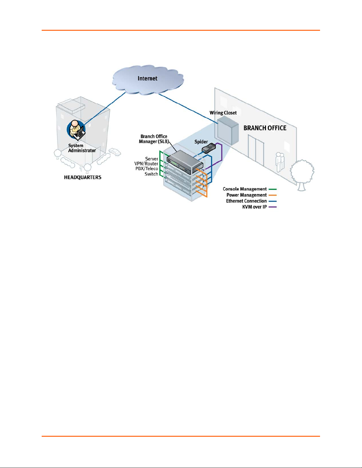
The SLB branch office manager enables IT System Administrators to manage remote
servers and IT infrastructure equipment securely over the Internet. This innovative device
combines the capabilities of the award-winning Lantronix® SLC™ console manager with
remote power management and an Ethernet switch into a compact, 1U rack-mountable
appliance.
Features
Console Management
8 serial ports for console connectivity
Enables system administrators to remotely manage Linux, Unix, and
Windows 2003 servers, routers, switches, telecom, and building access
equipment
Provides data logging, monitoring, and secure access control via the Internet
Power Management Outlets for Power Connectivity
4 outlets for power connectivity
Provides ability to control power individually to all attached equipment
Provides on/off/reboot control
Ensures safe power distribution and reduces in-rush current overload
Ethernet Switch
8 ports for network connectivity
Provides additional flexibility and scalability
Offers convenience
Reduces rack space
Integration with Other Secure IT Management Products
Can be combined with the Lantronix® Spider™ Distributed KVM to provide
a complete all-in-one “distributed IT” management solution.
Can integrate seamlessly with the Lantronix® SLM™ management appliance
and brings the “Branch to the Enterprise” for a complete end-to-end OOBI
enterprise management solution.
SLB™ Branch Office Manager User Guide 12
Page 13
2: Overview
Meets Needs of Branch Offices
Designed to meet the specific needs of the remote branch office, the SLB branch of f ic e
manager conserves rack space and reduces costs by enabling system administrators at
a main corporate facility to manage the IT equipment distributed among branch of fic es
simply and cost-effectively.
Branch offices are facilities that are typically remote or “distributed IT” locations, likely
located off-site of corporate headquarters or large-scale enterprise facilities. These
distributed facilities typically do not have an on-site maintenance staff or IT System
Administrator.
Typically, the branch office environment has some of the following characteristics:
Space is limited to 1U rack space or shelf mounted desktop unit
Closet-mounted or wall-attached rack
Limited air and power conditioning
Limited number of network devices and servers
No on-site maintenance staff
Ethernet or dial-up modem access is required
SLB™ Branch Office Manager User Guide 13
Page 14

2: Overview
Typical Equipment
You can configure, administer, and manage IT equipment in a variety of ways, but most
devices have one method in common: an RS-232 serial port, sometimes called a
console, auxiliary, or management port. These ports are often accessed directly by
connecting a terminal or laptop to them, meaning that the user must be in the same
physical location as the equipment. SLB devices give the user a way to access them
remotely from anywhere there is a network or modem connection.
The SLB can access and administer many types of equipment, such as:
Servers: Unix, Linux, Windows 2003, and others
Networking equipment: Routers, switches, storage networking
Telecom: PBX, voice switches
Other systems with serial interfaces: Heating/cooling systems,
security/building access systems, UPS, medial device.
Types of Business
The SLB branch office manager is used in many types of business, for example:
Banking and finance
Insurance companies
Healthcare
Retail Sales
Information Technology
Education and campus style facilities
Hospitality
Manufacturing Facilities
Benefits
The key benefits of using the SLB branch office manager:
Saves space: Compact design merges the functionality of three solutions into a
Saves money: Enables remote management and troubleshooting without
Saves time: Provides instant access and reduces response time, improving
Simplifies access: Enables 24/7 access to your equipment securely and
1U rack solution, reducing required rack space and total cost of ownership.
sending a technician onsite, resulting in reduced travel costs and increased
network uptime.
efficiency.
remotely after hours and on weekends and holidays—without having to schedule
visits or arrange for off-hour access.
Protects assets: Provides the highest levels of encryption and security features
(authentication, authorization, and IP filters) to ensure that your IT infrastructure
and data assets are protected.
SLB™ Branch Office Manager User Guide 14
Page 15

The SLB device also provides features such as convenient text menu systems, breaksafe operation, port buffering (logging), remote authentication, and Secure Shell (SSH)
access. Dial-up modem support ensures access when the network is not available.
Models
Two SLB models have the following hardware components:
2: Overview
Two Models: The SLB branch office manager is available in a 100-120 VAC
output model (SLB088411-01) with NEMA 5-15R type outlets and a 208-240
VAC output model (SLB088412-01) with IEC60320/C13 type outlets.
Power Outlets: Each model has four outlets that allow power management
and control (on/off/reboot) of the attached equipment using a simple web or
command line interface.
Serial Device Ports: Eight serial RS-232C (EIA-232) device ports are for
remote console management of the attached equipment. These match the
RJ45 pin-outs of the console ports of many popular devices found in a
network environment, and where different can be converted using Lantronix
adapters. See D: Adapters and Pinouts for more information on serial
adapters and pin-outs.
Unmanaged Ethernet Switch: A built-in 8-port unmanaged Ethernet switch
provides convenience and hel ps further reduce required rack space.
Ports and Modem Slots: The SLB branch office manager has two 10/ 100
Ethernet ports (referred to in this User Guide as Eth1 and Eth2) and a front
panel serial console port (RJ45). The SLB device has two 32-bit CardBus
(PC card) slots to support storage cards or a PC Card modem for dial-in
access. The list of supported cards is available on the Lantronix website.
Table 2-1. SLB Models
Part Number Model and Description
SLB088411-01
SLB branch office manager, 8 device ports, 8 Ethernet switch
ports, 4 power outlets (100-120 VAC, NEMA 5-15R type), 1 AC
power supply
SLB088412-01
SLB branch office manager, 8 device ports, 8 Ethernet switch
ports, 4 power outlets (208-240 VAC, IEC60320/C13 type), 1
AC power supply
SLB™ Branch Office Manager User Guide 15
Page 16
2: Overview
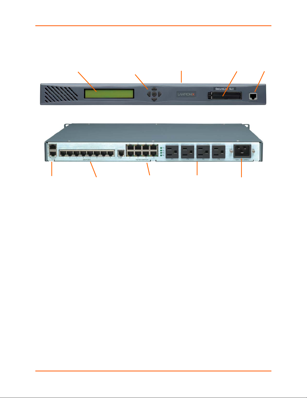
Two-Line
LCD Display
Front Panel
1U Tall, Self-Contained
Two 10/100 Network Ports
RS-232 Device Ports (1-8)
AC Power Input
Two PC Card Slots
Console Port
(RS-232)
Four Power Outlets
8 Switch Ports
Figure 2-1. SLB 8 Front
Pushbuttons
Rack-Mountable Chassis
Figure 2-2. SLB 8 Back — 8 Device Ports, 4 Power Outlets, 8 Switch Ports; 1 AC Power Supply
System Features
The SLB firmware has the following basic capabilities:
Connects up to eight RS-232 serial consoles
Controls power (on/off/reboot) of up to four attached devices
10Base-T/100Base-TX Ethernet network compatibility
Buffer logging to file
Email and SNMP notification
ID/Password security, configurable access rights
Secure shell (SSH) security; supports numerous other security protocols
Network File System (NFS) and Common Internet File System (CIFS) support
Telnet or SSH to a serial port by IP address per port or by IP address and TCP
port number
Configurable user rights for local and remotely authenticated users
Support for an internal PC Card modem or an external modem
Sun break-safe (no unintentional break ever sent to attached servers)
Simultaneous access on the same port-- "listen" and "direct" connect mode
Local access through a console port
Web administration (using most browsers)
SLB™ Branch Office Manager User Guide 16
Page 17

2: Overview
Protocols Supported
The SLB branch office manager supports the TCP/IP network protocol as well as:
SSH, Telnet, PPP, NFS, and CIFS for connections in and out of the SLB device
SMTP for mail transfer
DNS for text-to-IP address name resolution
SNMP for remote monitoring and management
FTP and SFTP for file transfers and firmware upgrades
TFTP and HTTPS for firmware upgrades
DHCP and BOOTP for IP address assignment
HTTPS (SSL) for secure browser-based configuration
NTP for time synchronization
LDAP, NIS, RADIUS, CHAP, PAP, Kerberos, and TACACS+ for user
authentication
For brief descriptions of these protocols, see Appendix Protocol Glossary.
Access Control
The system administrator controls access to attached servers or devices by assigning
access rights to up to 128 user profiles. Each user has an assigned ID, pass wor d, and
access rights. Other user profile access options may include externally configured
authentication methods such as RADIUS, TACACS+, NIS, and LDAP.
Power Outlet Control
With the SLB branch office manager’s built-in power management capability, system
administrators can remotely control the power (on/off/reboot) individually to all IT
equipment in the branch office, ensure safe power distribution, and reduce “in-rush”
current overload. If SNMP traps are enabled, a trap (alarm) is sent if the total current for
all outlets exceeds a threshold.
Device Port Buffer
The SLB device supports real-time data logging for each device port. The port can save
the data log to a file, send an email notification of an issue, or take no action.
You can define the path for logged data on a port-by-port basis, configure file size and
number of files per port for each logging event, and configure the device log to send an
email alert message automatically to the appropriate parties indicating a particular error.
Configuration Options
You may use the backlit front-panel LCD display for initial setup and configuration and to
view current network, console, and date/time settings, and get power outlet status.
Both a web interface viewed through a standard browser and a command line interface
(CLI) are available for configuring the SLB settings and monitoring performance.
SLB™ Branch Office Manager User Guide 17
Page 18
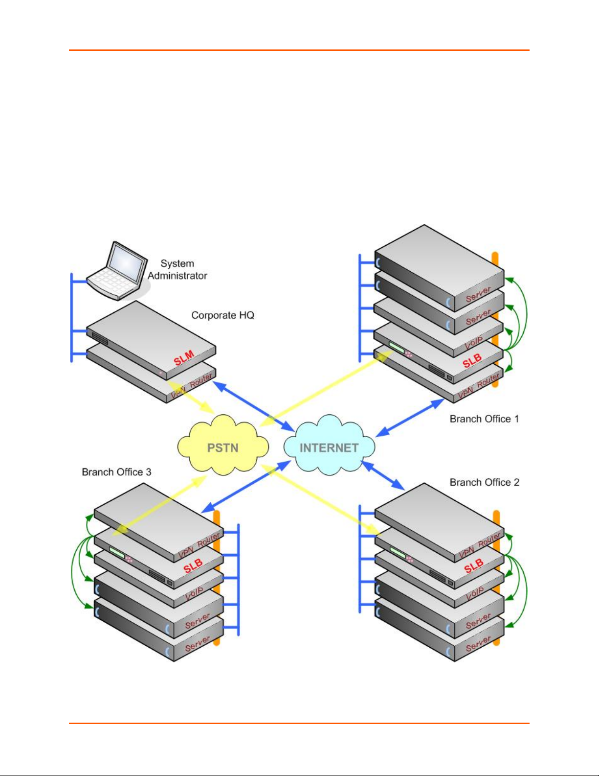
Application Example
The figure below is an example deployment. An SLB branch office manager is deployed
in each branch office and an (optional) SLM management appliance at the main office.
The branch offices are interconnected (always on) by VPN routers overlaid on the
Internet, and also interconnected (on demand) through the analog phone system.
Note: The SLB branch office manager can also be the authentication gateway to a
network architecture that is not VPN-based.
The SLB device provides Ethernet switch service (blue), remotely controlled and
monitored AC power (orange), console management (green), and traditional, wir e d
telephone network (PSTN) access (yellow).
2: Overview
SLB™ Branch Office Manager User Guide 18
Page 19

A system administrator, upon losing IP connectivity to a server, takes the following steps:
Views the server’s Ethernet interface state information provided by the SLB
branch office manager.
If the Ethernet interface is faulty, connects to the server’s console port by means
of the SLB web page or CLI (optionally via the SLM management appliance) and
checks the server’s system parameters.
If the server is not responsive on the console port, commands the SLB branch
office manager to reboot the server’s power.
If the entire branch office loses IP connectivity, dial in to the SLB device to
perform the diagnostic functions
Hardware Features
The SLB hardware includes the following:
1U-tall (1.75 inch) rack-mountable appliance
2 10Base-T/100Base-TX network ports
1 front panel serial console port for VT100 terminal or PC with emulation
2 PC Card slots
2: Overview
Front panel LCD display and keypad
256 KB-per-port buffer memory for serial device ports
8-port unmanaged Ethernet switch with auto MDI/MDIX function
8 RS-232 serial device ports connected via Category 5 (RJ45) wiring
AC Power Input:
− SLB088411-01 model:
- (1) IEC-60320/C20 inlet, 100-120 VAC, 50/60Hz
- (20A Branch Circuit) 16A max input current
- (15A Branch Circuit) 12A max input current
2
1
− SLB088412-01 model:
- (1) IEC-60320/C20 inlet, 100-240 VAC, 50/60Hz
- (20A Branch Circuit) 15A max input current
Power Outlets (Total Switched Power):
− SLB088411-01 model:
- (4) NEMA 5-15R outlets, 100-120 VAC, 50/60Hz
- (20A Branch Circuit) 15A max per outlet, 16A total
- (15A Branch Circuit) 12A max per outlet, 12A total
2
1
− SLB088412-01 model
- (4) IEC-60320/C13 outlets, 208-240 VAC , 50/60Hz
- (20A Branch Circuit) 10A max per outlet, 15A total
Note: The outlet voltage equals the input voltage.
Convection cooled, silent operation, low power consumption
Note: For more detailed information, see Technical Specifications on
page 23.
1
The max input/output current is de-rated to 12A when using the supplied NEMA
5-15P (15A) cable (p/n SLPP012310-01).
SLB™ Branch Office Manager User Guide 19
Page 20
2: Overview
2
The max input/output current is de-rated to 16A when using the optional NEMA
5-20P (20A) cable (p/n SLPP012410-01, SLP P01 251 0-01, SLPP0 12 610-01).
Serial Connections
All devices attached to the device ports and the console port must support the RS-232C
(EIA-232) standard. Category 5 cabling with RJ45 connections is used for the device port
connections and for the console port. (For pin out inf ormation, see D: Adapters and
Pinouts.)
Note: RJ45 to DB9/DB25 adapters are available from Lantronix.
Device ports and the console port support eight baud-rate options: 300, 600, 1200, 2400,
4800, 9600, 19200, 38400, 57600, and 115200 baud.
Figure 2-3. Device Port Connections
Figure 2-4. Console Port Connection
SLB™ Branch Office Manager User Guide 20
Page 21
2: Overview
Network Connections
The SLB network interfaces are 10Base-T/100Base-TX connectors for use with a
conventional Ethernet network. Use standard RJ45-terminated Category 5 cables.
Network parameters must be configured before the SLB branch office manager can be
accessed over the network.
Note: One possible use for the two Ethernet ports is to have one port on a
private, secure network and the other on a public, unsecured network.
Figure 2-5. Network Connection
PC Card Interface
The SLB has two PC Card slots. Lantronix qualifies cards continuously and publishes a
list of qualified cards on the Lantronix web site.
Figure 2-6. PC Card Interface
SLB™ Branch Office Manager User Guide 21
Page 22

Adapters:
ADP010104-01
500-184-R
3: Installation
This chapter provides a high-level procedure for installing the SLB branch office manager
followed by more detailed information about the SLB connec t ions and po w er supp lies.
Caution: To avoid physical and electrical hazards, please be sure to read
C: Safety Information before installing the SLB device.
What’s in the Box
In addition to the SLB branch office manager, the box contains the following items:
Part # Component Description
200.2066A
200.2067A
200.2069A
200.2070A
Note: An optional adapter for external modems is also avail able f rom Lantronix: 200.2073
Adapter: DB25M (DCE) to RJ45, external modems.
Cables:
200.0063
500-153
Power Cords:
SLPP12310-01*
SLPP12810-01**
Adapter: DB25M (DCE), Sun w/DB25 female
Adapter: DB25F (DCE) to RJ45, Sun w/DB25 male and some
HP9000’s
Adapter: DB9M (DCE) to RJ45, SGI Onyx
Adapter: DB9F (DCE) to RJ45, HP9000, SGI Origin, IBM RS6000,
and PC-based Linux servers
Adapter: RJ45 rolled serial, Cisco, and Sun Netra
Cable: RJ45 to RJ45, Cat-5, 1 Ft (.3m)
Cable: RJ45 to RJ45, Cat-5, 6.6 ft (2 m)
Cable: RJ45 Loopback
Inlet cord: IEC60320/C19 to NEMA 5-15P (15A), 8 FT.
Inlet cord: IEC60320/C19 to Schuko (EU), 8 Ft.
SLPP12910-01**
SLPP12A08-01**
Notes: * Included with SLB088411E-01, ** Included with
Inlet cord: IEC60320/C19 to BS1363 (UK), 8 Ft.
Inlet cord: IEC60320/C19 to AS3112 (AUS/NZ), 8 Ft.
SLB088412E-01
SLB™ Branch Office Manager User Guide 22
Page 23

Verify and inspect the contents of the SLB package using the enclosed packing slip or
the table above. If any item is missing or damaged, contact your place of purchase
immediately.
Product Information Label
The product information label on the underside of the SLB branch office manager
contains the following information about each SLB device:
Part Number
Serial Number Bar Code
Serial Number and Date Code
Regulatory Certifications and Statements
Technical Specifications
Table 3-1. SLB Technical Specifications
3: Installation
Serial Interface (Device)
Serial Interface (Console)
Power Input
Power Outlets
Ethernet Switch
Network Interface
Power Supply
(8) RJ45-type 8-conductor connector (DTE)
Speed software selectable (300 to 115,200 baud)
(1) RJ45-type 8-pin connector (DTE )
Speed software selectable (300 to 115,200 baud)
Model SLB088411-01:
- (1) IEC-60320/C20 inlet, 100-120 VAC, 50/60Hz
- (20A Branch Circuit) 16A max input current
- (15A Branch Circuit) 12A max input current
Model SLB088412-01:
- (1) IEC-60320/C20 inlet, 100-240 VAC, 50/60Hz
- (20A Branch Circuit) 15A max input current
Model SLB088411-01:
- (4) NEMA5-15R outlets, 100-120 VAC, 50/60Hz
- (20A Branch Circuit) 15A max per outlet, 16A total
- (15A Branch Circuit) 12A max per outlet, 12A total
Model SLB088412-01:
- (4) IEC60320/C13 outlets, 208-240 VAC, 50/60Hz
- (20A Branch Circuit) 10A max per outlet, 15A total
(8) Ethernet switch ports (unmanaged) with auto MDI/MDIX
10Base-T/100Base-TX RJ45 Ethernet
(1) Universal AC power input: 100-240 VAC, 50 or 60 Hz
IEC-type regional cord set included
2
1
2
1
Power Consumption
Dimensions
Weight
Temperature
Less than 20 watts
1U, 1.75 in x 17.25 in x 12 in
10 lb.
Operating: 0 to 50 °C (32 to 122 °F)
Storage: -20 to 70 °C (-4 to 158 °F)
SLB™ Branch Office Manager User Guide 23
Page 24

3: Installation
Relative Humidity
Heat Flow Rate
Current measurement
accuracy
1
The max input/output current is de-rated to 12A when using the supplied NEMA
5-15P (15A) cable (p/n SLPP012310-01).
2
The max input/output current is de-rated to 16A when using the optional NEMA
5-20P (20A) cable (p/n SLPP012410-01, SLP P01 251 0-01, SLPP0 12 610-01).
Physical Installation
To install the SLB branch office manager in a rack:
1. Place the SLB device in a 19-inch rack.
Warning: Be careful not to block the air vents o n the sides of the SLB
branch office manager. If you mount the SLB in an enclosed rack, we
recommended that the rack have a ventilation fan to provide adequate
airflow through the SLB.
2. Connect the serial device(s) to the SLB device ports. See on page 25.
3. Install any PC Cards you intend to use. If you install a modem card, connect to the
phone line. See 9: PC Cards.
Operating: 10% to 90% non-condensing
Storage: 10% to 90% non-condensing
68 BTU per hour
± 12%
4. You have the following options:
a) To configure the SLB branch office manager using the network, or to monitor
serial devices on the network, connect at least one SLB network port to a
network. See Connecting to a Network Port on page 25.
b) To configure the SLB branch office manager usi ng a dumb terminal or a
computer with terminal emulation, connect the terminal or PC to the SLB
console port. See Connecting a Terminal on page 25.
5. Connect the power cord, and apply power. See Connecting to a Power Source on
page 26 .
6. Wait approximately a minute and a half for the boot process to complete.
When the boot process ends, the SLB host name and the clock appear on the LCD
display.
Now you are ready to configure the network settings as described in 4: Quick Setup.
SLB™ Branch Office Manager User Guide 24
Page 25
3: Installation
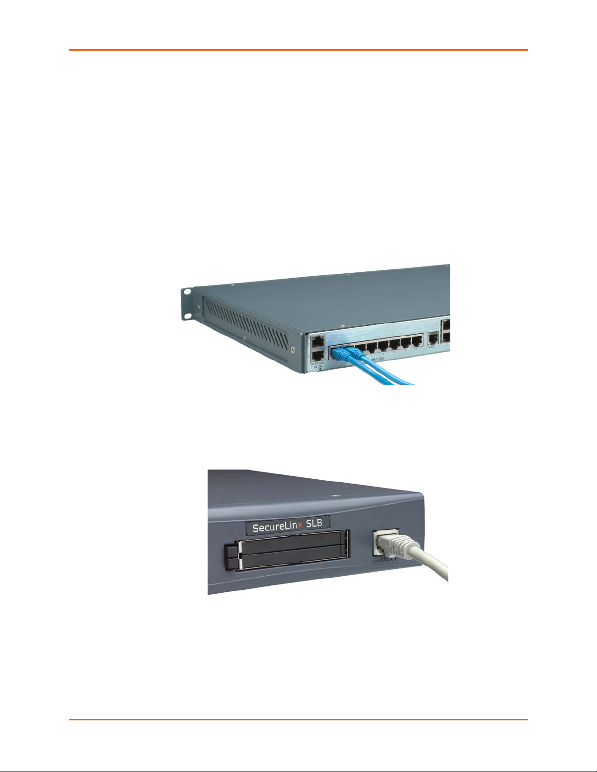
Connecting to a Device Port
You can connect any device that has a serial console port to a device port on the SLB
branch office manager for remote administration. The console port must support the RS232C interface.
Note: Many servers must either have the serial port enabled as a console or the
keyboard and mouse detached. Consult the server hardware and/or software
documentation for more informat ion.
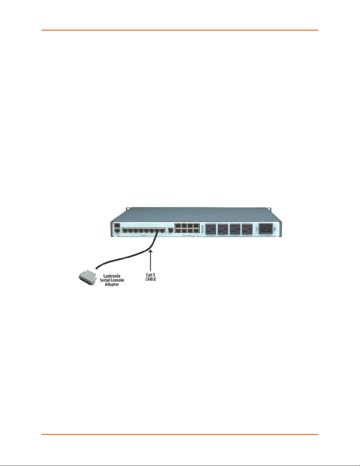
To connect to a device port:
1. Connect one end of the Cat 5 cable to the device port.
2. Connect the other end of the Cat 5 cable to a Lantronix serial console adapter.
Note: To connect a device port to a Lantronix® SLP™ management appliance, use the
rolled serial cable provided with the SLB branch office manager, a 200.2225 adapter and
Cat 5 cabling, or the ADP010104 adapter that eliminates the need for an additional Cat5
patch cable between the adapter and the connected equipment. See D: Adapters and
Pinouts for more information about Lantronix adapters.
3. Connect the adapter to the serial console of the serial device.
Figure 3-1. CAT 5 Cable Connection
Connecting to a Network Port
The SLB device’s network ports (10Base-T/100Base-TX) allow remote access to the
attached devices and the system administrative functions. Use a standard RJ45terminated Category 5 cable to connect to the network port.
Note: One possible use for the two Ethernet ports is to have one port on a
private, secure network, and the other on an unsecured network.
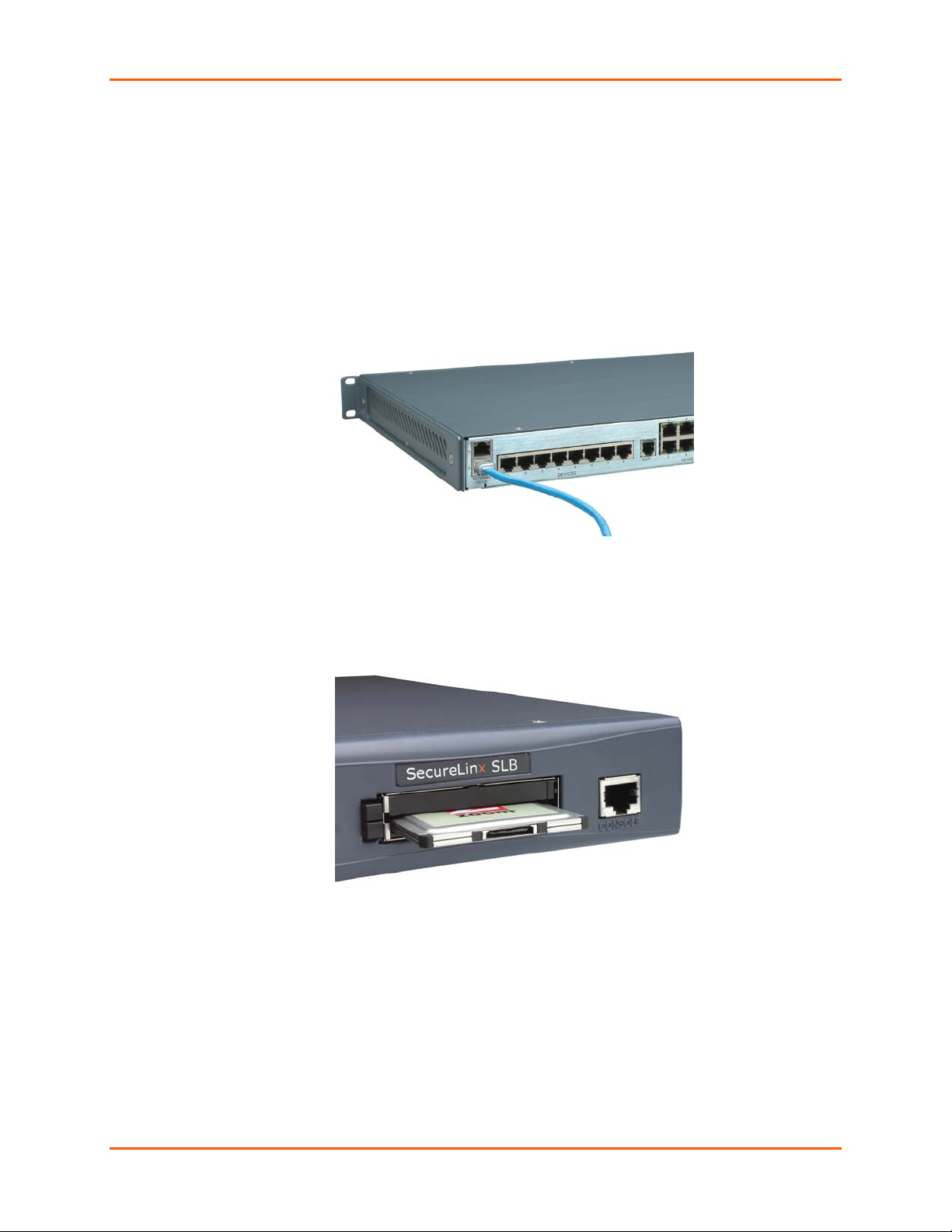
Connecting a Terminal
The console port is for local access to the SLB branch office manager and the attached
devices. You may attach a dumb terminal or a computer with terminal emulation to the
console port. The SLB console port uses RS-232C protocol and supports VT100
emulation. The default baud rate is 9600.
To connect the console port to a terminal or computer with terminal emulation, Lantronix
offers optional adapters that provide a connection between an RJ45 jack and a DB9 or
DB25 connector. The console port is configured as DTE. For more information,
SLB™ Branch Office Manager User Guide 25
Page 26
3: Installation
see D: Adapters and Pinouts and our web site at www.lantronix.com/support an d c lic k
Cable/Adapter Lookup
To connect a terminal:
1. Attach the Lantronix adapter to your terminal (use PN 200.2066A adapter) or your
PC's serial port (use PN 200.2070A adapter).
2. Connect the Cat 5 cable to the adapter, and connect the other end to the SLB
console port.
3. Turn on the terminal or start your computer’s communication program (e.g.,
HyperTerminal for Windows).
4. Once the SLB branch office manager is running, press Enter to establish
connection. You should see the model name and a login prompt on your terminal.
You are connected.
on the Support menu.
Connecting to a Power Source
The SLB branch office manager consumes less than 20W of electrical power.
The SLB device has a universal auto-switching AC power supply. The power supply
accepts AC input voltage between 100 and 240 VAC with a frequency of 50 or 60 Hz.
Rear-mounted IEC-type AC power connector(s) are provided for universal AC power
input (see page 22 for included power cords).
Figure 4-2. AC Power Input
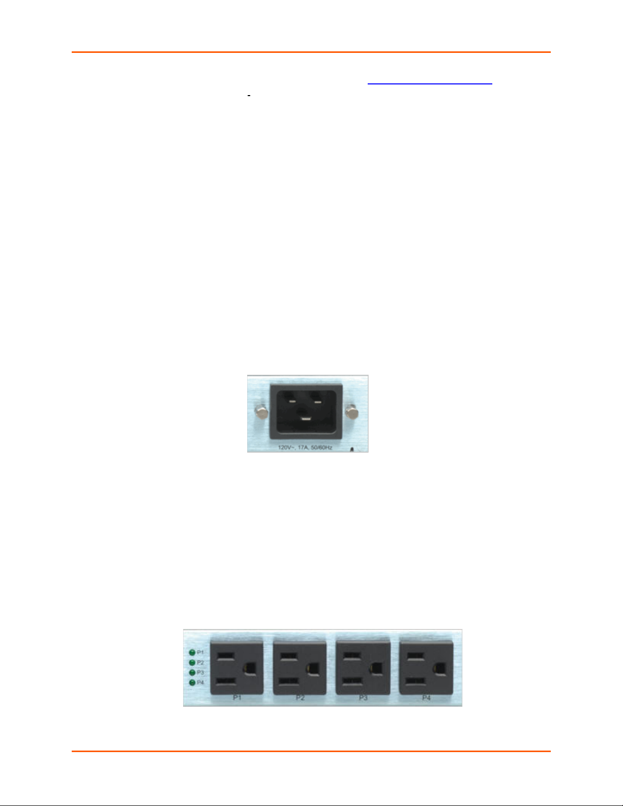
Connecting Devices to Power Outlets
To avoid the possibility of noise due to arcing:
1. Keep the device’s on/off switch in the off position until after it is plugged into
the outlet, or log in to the unit and turn the outlets off before connecting the
devices.
2. Connect devices to the outlets.
There are four power outlet status LEDs next to outlet number 1. The status LED
for outlet 1 is at the top. If the LED for an outlet is dark the outlet is turned off; if it is
lit the outlet is turned on.
Figure 3-2. Power Outlets
SLB™ Branch Office Manager User Guide 26
Page 27
3: Installation
The status of the power outlets displays on the front panel LCD display as the
default display.
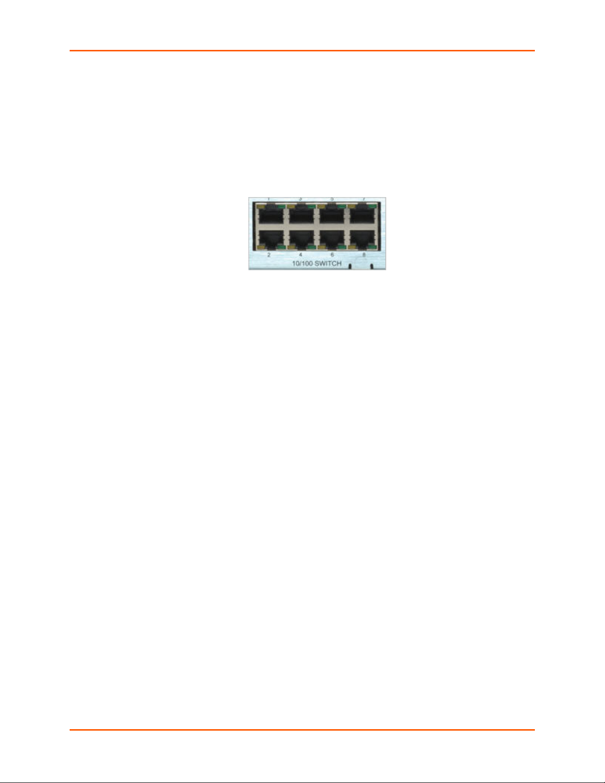
Connecting Devices to the 8-Port Ethernet Switch
To connect devices to the unmanaged Ethernet switch:
1. Use the included 1Ft Ethernet patch cable to connect Ethernet port 1 on the SLB
branch office manager to one of the switch ports.
Figure 3-3. 8-Port Ethernet Switch
Note: The eight unmanaged Ethernet ports are not internally connected
to the other two Ethernet ports.
2. Use a standard Ethernet patch cable to connect another switch port to your
network.
3. Up to 6 more Ethernet devices may be connected to your network. Use standard
Ethernet patch cables from the Ethernet devices to the SLB device's switch ports.
An example of a standard Ethernet patch cable is the Lantronix 200.0062 RJ45 TO
RJ45 CAT5 CABLE (LAN PINNING) 6.6 Ft.
Typical Installations
Following are illustrations showing some typical ways to install the SLB branch of fice
manager. In Figure 3-4, three serial devices (a server, a Cisco switch, and a firewall)
connect to the SLB device's serial ports, unmanaged switch ports, and power outlets.
This setup enables the SLB branch office manager to manage the devices, connect the
devices to the network, and provide power to the devices. An SLB switch port connects
the Lantronix Spider (optional), a “Distributed KVM” product that provides remote and
secure access to the attached server over the network. In addition, the SLB branch office
manager connects to a modem for out-of-band dial-up access.
SLB™ Branch Office Manager User Guide 27
Page 28
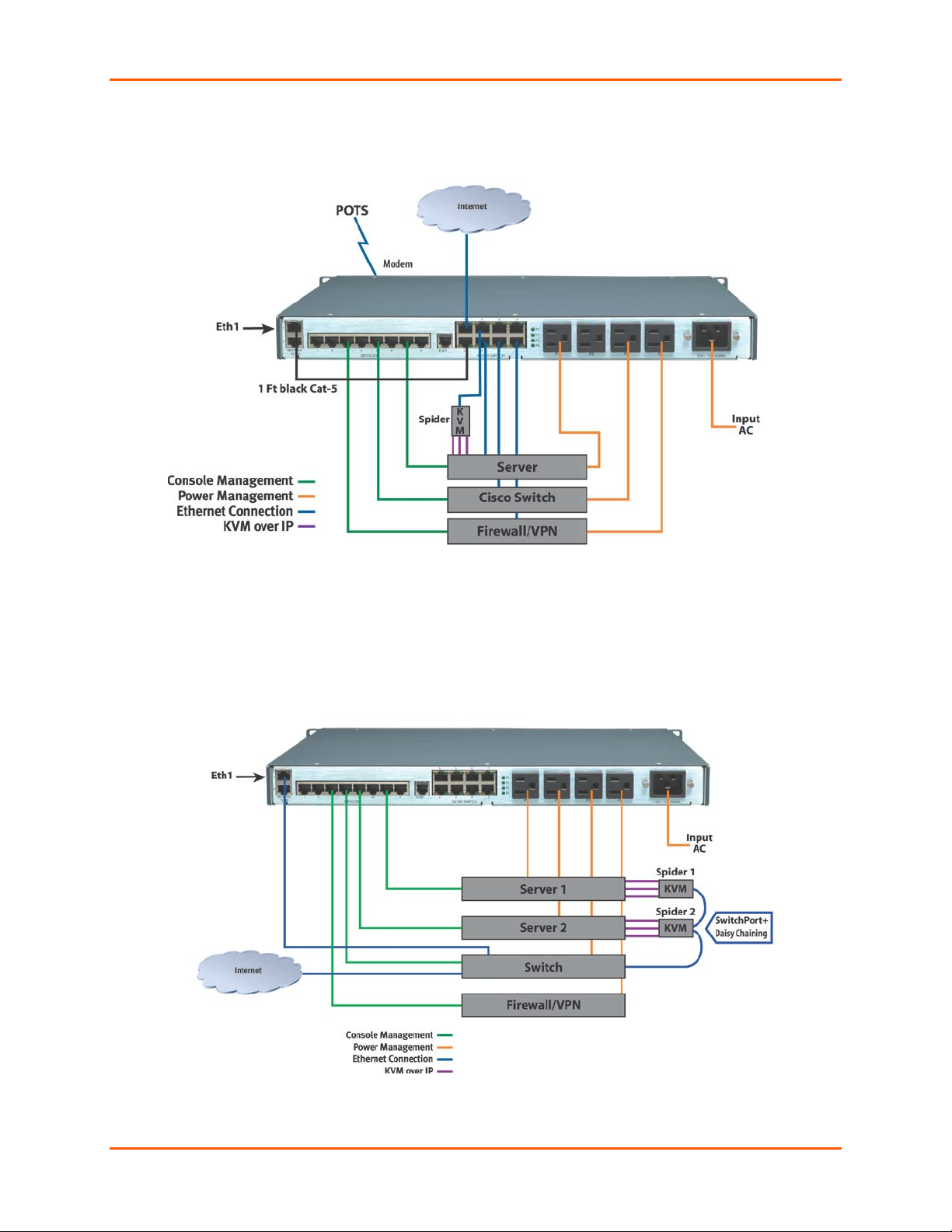
Figure 3-4. SLB Installation Using the Integrated Ethernet Switch
3: Installation
In Figure 3-5, the SLB branch office manager controls four serial devices and
provides power to them. The devices use a managed switch to connect to the
network. The figure also shows how Lantronix Spiders can be daisy chained.
Figure 3-5. SLB Installation Using a Managed Switch
SLB™ Branch Office Manager User Guide 28
Page 29

DHCP
A DHCP server automatically assigns th e IP addre ss and ne tw or k
BOOTP
Similar to DHCP but for smaller networks.
Detector
A Windows-based application downloadab le at
4: Quick Setup
This chapter helps get the IP network port up and running quickly, so you can administer
the SLB branch office manager using your network. To set up the network connections
quickly, we suggest you do one of the following:
Use the front panel LCD display and pushbuttons.
Complete the Quick Setup web page on the web interface.
SSH to the command line interface and follow the Quick Setup script on the
command line interface.
Connect to the console port and follow the Quick Setup script on the
command line interface.
Note: The first time you power up the SLB unit, Eth1 tries to obtain its IP address
via DHCP. If you have connected Eth1 to the network, and Eth1 is able to acquire
an IP address, you can view this IP address on the LCD or Lantronix® Detector™
(downloadable at http://www.lantronix.com/support/downloads/
acquire an IP address, you cannot use Telnet, SSH, or the web interface to run
Quick Setup.
). If Eth1 cannot
IP Address
Your SLB branch office manager must have a unique IP address on your network. The
system administrator generally provides the IP address and corresponding subnet mask
and gateway. The IP address must be within a valid range, unique to your network, and
in the same subnet as your PC.
You have the following options for assigning an IP address to your SLB device.
Table 4-1. Methods of Assigning an IP Address
Method Description
settings. The SLB branch office manager is DHCP-enabled by
default.
With the Eth1 network port connected to the network, and the SLB
device powered up, Eth1 acquires an IP address, viewable on the
LCD.
At this point, you can Telnet into the SLB branch office manager, or
use the web interface.
http://www.lantronix.com/support/downloads/ for viewing a DHCP-
provided IP address or for assigning a static IP address to the SLB
branch office manager. You can use Detector only if you have not
already assigned a static IP address by another method. For more
information, see Detector’s online help.
SLB™ Branch Office Manager User Guide 29
Page 30
4: Quick Setup
Method
Description
Front panel LCD
You manually assign the IP address and other basic network,
Serial port login to
You assign an IP address and configure the SLB branch office
display and
pushbuttons
command line
interface
console, and date/time settings. If desired, you can restore the
factory defaults.
manager using a terminal or a PC running a terminal emulation
program to the SLB device’s serial console port connection.
Method #1 Using the Front Panel Display
Before You Begin
Make sure you know:
An IP address that will be unique and valid on your network (unless
automatically assigned)
Subnet mask (unless automatically assigned)
Gateway
DNS settings
Date, time, and time zone
Console port settings: baud rate, data bits, stop bits, parity, and flow control
Make sure the SLB branch office manager is plugged in to power and turned on.
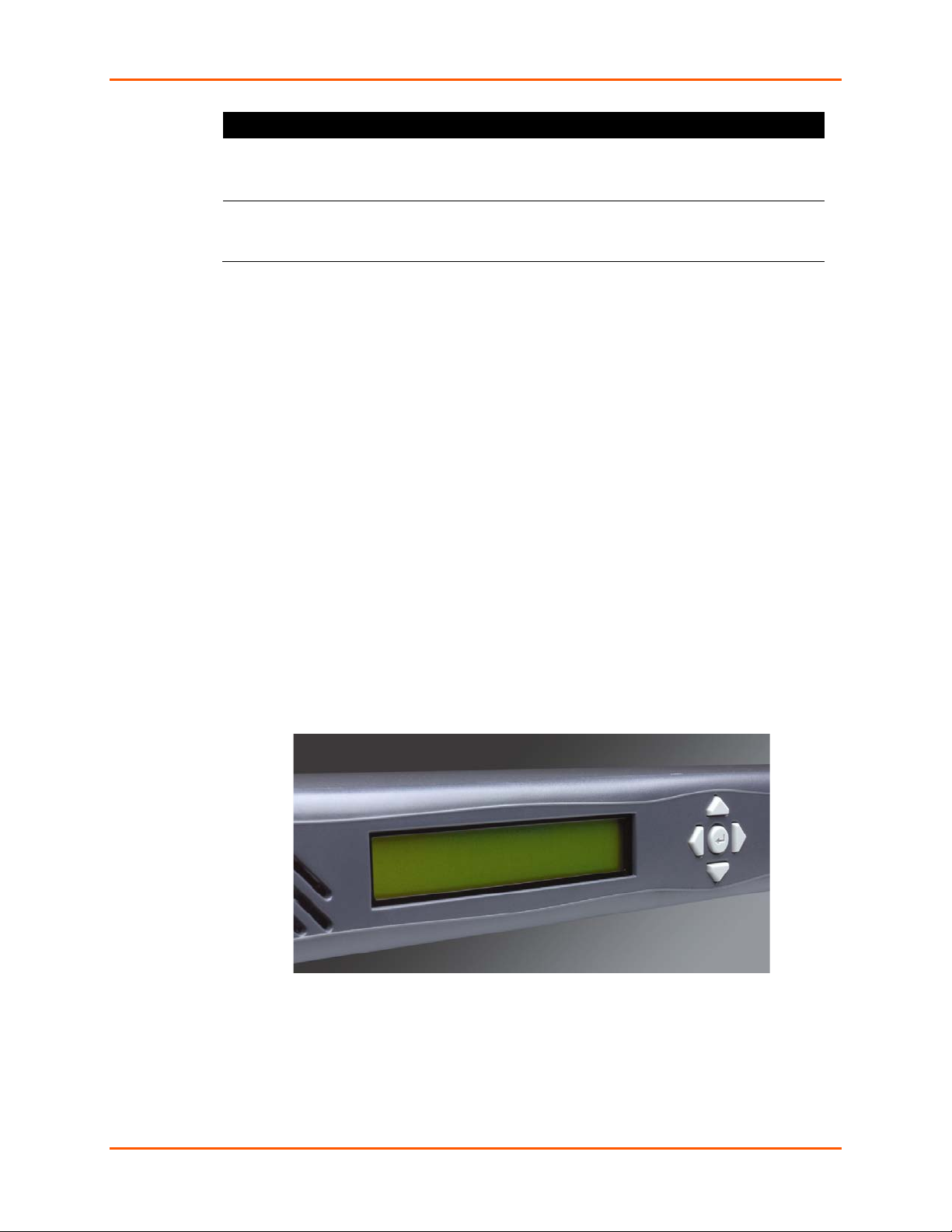
Front Panel LCD Display and Pushbuttons
With the SLB device powered up, you can use the front panel display and pushbuttons to
set up the basic parameters.
Figure 4-1. Front Panel LCD Display and Five Pushbuttons (Enter, Up, Down, Left, Right)
The front panel display initially shows the hostname (abbreviated to 14 letters), total
current level, and state of the four outlets.
When you click the right-arrow pushbutton, the SL B device's network settings display.
Using the five pushbuttons, you can change the network, console port, and date/time
settings and view the firmware release version. If desired, you can restore the factory
defaults.
SLB™ Branch Office Manager User Guide 30
Page 31

4: Quick Setup
To move to the next option (e.g., from Network Settings to
To return to the previous option
Eth1 IP Address
Baud Rate
Time Zone
Firmware version and
Eth1 Subnet Mask
Date/Time
Gateway
DNS1
DNS2
DNS3
right/left arrow
up/down arrow
Note: Have your information handy as the display times out without accepting
any unsaved changes if you take more than 30 seconds between entries.
Any changes made to the network, console port, and date/time settings take effect
immediately.
Navigating
The front panel has one Enter button (in the center) and four arrow buttons (up, left,
right, and down). Press the arrow buttons to navigate from one option to another, or to
increment or decrement a numerical entry of the selected option. Use the Enter button to
select an option to change or to save your settings.
Action Button
Console Settings)
right arrow
left arrow
To enter edit mode
Within edit mode, to increase or decrease a numerical
entry
Within edit mode, to move the cursor right or left
To exit edit mode
To scroll up or down the list of parameters within an option
(e.g., from IP Address to Mask)
Table 4-2. Front Panel Setup Options with Associated Parameters
Enter (center button)
up and down arrows
right or left arrows
Enter
up and down arrows
Normal Network
Settings
Console
Settings
Data Bits
Stop Bits
Parity
Flow Control
Date /
Time
Settings
Release
date code (display only)
Restore Factory
Defaults
Entering the Settings
To enter setup information:
1. From the normal display (host name, date and time), press the right arrow button
SLB™ Branch Office Manager User Guide 31
to display Network Settings. The IP address for Eth1 displays.
Page 32

4: Quick Setup
Note: If you have connected Eth1 to the network, and Eth1 is able to acquire
an IP address through DHCP, this IP address displays, followed by the letter
[D]. Otherwise, the IP address displays as all zeros (000.000.000.000).
2. Press the Enter button on the keypad to enter edit mode. A cursor displays below
one character of the existing IP address setting.
3. To enter values:
Use the left or right arrow to move the cursor to the left or to the right position.
Use the up or down arrow to increment or decrement the numerical value.
4. When you have the IP address as you want it, press Enter to exit edit mode, and
then press the down arrow button. The Subnet Mask parameter displays.
Note: You must edit the IP address and the Subnet Mask together for a valid
IP address combination.
5. To save your entries for one or more parameters in the group, press the right
arrow button. The Save Settings? Yes/No prompt displays.
Note: If the prompt does not display, make sure you are no longer in edit
mode.
6. Use the left/right arrow buttons to select Yes, and press the Enter button.
7. Press the right arrow button to move to the next option, Console Settings.
8. Repeat steps 2-7 for each setting.
9. Press the right arrow button to move to the next option, Date/Time Settings, and
click Enter to edit the time zone.
a) To enter a US time zone, use the up/down arrow buttons to scroll through the
US time zones, and then press Enter to select the correct one.
b) To enter a time zone outside the US, press the left arrow button to move up to
the top level of time zones. Press the up/down arrow button to s crol l
through the top level.
A time zone with a trailing slash (such as Africa/) has sub-time zones. Use the
right arrow button to select the Africa time zones, and then the up/down
arrows to scroll through them.
Press Enter to select the correct time zone. To move back to the top-level time
zone at any time, press the left arrow.
10. To save your entries, press the right arrow button. The Save Settings? Yes/No
prompt displays.
Note: If the prompt does not display, make sure you are no longer in edit
mode.
11. Use the left/right arrow buttons to select Yes, and press the Enter button.
12. To review the saved settings, press the up or down arrows to step through the
current settings.
When you are done, the front panel returns to the clock display. The network port
resets to the new settings, and you can connect to your IP network for further
administration. You should be able to Telnet or SSH to the SLB branch office
manager through your network connection, or access the web interface through a
web browser.
SLB™ Branch Office Manager User Guide 32
Page 33

Restoring Factory Defaults
To use the LCD display to restore factory default settings:
1. Press the right arrow button to move to the last option, Release.
2. Use the down arrow to move to the Restore Factory Defaults option. A prompt
for the 6-digit Restore Factory Defaults password displays.
3. Press Enter to enter edit mode.
4. Using the left and right arrows to move between digits and the up and down
arrows to change digits, enter the password (the default password is 999999).
Note: The Restore Factory Defaults password is only for the LCD. You can change
it at the command line interface using the admin keypad password command.
5. Press Enter to exit edit mode. If the password is valid, a Save Settings? Yes/No
prompt displays.
6. To initiate the process for restoring factory defaults, select Yes. When the process
is complete, the SLB reboots.
Method #2 Quick Set up on the Web Page
4: Quick Setup
After the unit has an IP address, you can use the Quick Setup web page to configure the
remaining network settings. This page displays the first time you log into the SLB only.
Otherwise, the SLB Home Page displays. (For information about the web interface, see
Web Interface on page 40.)
To complete the Quick Setup page:
1. Open a standard web browser. Lantronix supports the latest versions of Internet
Explorer, Mozilla Firefox, Safari, Opera or Chrome web browsers.
2. In the URL field, type https:// followed by the IP address of your SLB.
Note: The web server listens for requests on the unencrypted (HTTP) port (port 80)
and redirects all requests to the encrypted (HTTPS) port (port 443).
3. Log in using sysadmin as the user name and PASS as the password. The first
time you log in to the SLB, the Quick Setup page automatically displays.
Otherwise, the Home page displays.
Note: To open the Quick Setup page at another time, click the Quick Set up tab.
SLB™ Branch Office Manager User Guide 33
Page 34

4: Quick Setup
4. To accept the defaults, select the Accept default Quick Setup settings checkbox
in the top portion of the page and click the Apply button at the bottom of the page.
Otherwise, continue with step 5.
Note: Once you click the Apply button on the Quick Setup page, you can
continue using the web interface to configure the SLB branch office manager
further.
5. Enter the following:
Network Settings
Note: Configurations with the same IP subnet on multiple interfaces (Ethernet or PPP)
are not currently supported.
SLB™ Branch Office Manager User Guide 34
Page 35

4: Quick Setup
Eth 1 Settings Disabled: If selected, disables the network port. Default is
Eth1 enabled.
Obtain from DHCP: Acquires IP address, subnet mask,
hostname and gateway from the DHCP server. (The DHCP
server may not provide the hostname gateway, depending
on its setup.) This is the default setting. If you select this
option, skip to Gateway.
Obtain from BOOTP: Lets a network node request
configuration information from a BOOTP "server" node. If
you select this option, skip to Gateway.
Specify: Lets you manually assign a static IP address,
generally provided by the system administrator.
IP Address (if
specifying)
Subnet Mask
Default Gateway
Hostname
Domain
Enter an IP address that will be unique and valid on your
network. There is no default.
Enter all IP addresses in dot-quad notation. Do not use
leading zeros in the fields for dot-quad numbers less than
100. For example, if your IP address is 172.19.201.28, do
not enter 028 for the last segment.
Note: Currently, the SLB branch office manager does not
support configurations with the same IP subnet on multiple
interfaces (Ethernet or PPP).
If specifying an IP address, enter the network segment on
which the SLB device resid es. There is no default.
The IP address of the router for this network. There is no
default.
The default host name is slbXXXX, where XXXX is the last
4 characters of the hardware address of Ethernet Port 1.
There is a 64-character limit (contiguous characters, no
spaces). The host name becomes the prompt in the
command line interface.
If desired, specify a domain name (for example,
support.lantronix.com). The domain name is used for host
name resolution within the SLB branch office manager. For
example, if abcd is specified for the SMTP server, and
mydomain.com is specified for the domain, if abcd cannot
be resolved, the SLB device attempts to resolve
abcd.mydomain.com for the SMTP server.
Date & Time Settings
Change Date/Time
Date
Time
Time Zone
SLB™ Branch Office Manager User Guide 35
Select the checkbox to manually enter the date and time
at the SLB branch office manager’s location.
From the drop-down lists, select the current month, day,
and year.
From the drop-down lists, select the current hour and
minute.
From the drop-down list, select the appropriate time zone.
Page 36

Administrator Settings
4: Quick Setup
Sysadmin
Password/ Retype
Password
To change the password (e.g., from the default) enter a
password of up to 64 characters.
6. To save your entries, click the Apply button.
SLB™ Branch Office Manager User Guide 36
Page 37

4: Quick Setup
Method #3 Quick Set up on the Command Line Int erface
If the SLB branch office manager does not ha ve an IP addres s , you can connect a dumb
terminal or a PC running a terminal emulation program (VT100) to access the command
line interface. (See Connecting a Terminal on page 25.) If the unit has an IP address, you
can use SSH or Telnet to connect to the SLB device.
Note: By default, Telnet is disabled and SSH is enabled. To enable Telnet, use the
Services web page (see 7: Services), a serial terminal connection, or an SSH connection.
To complete the command line interface Quick Setup script:
1. Do one of the following:
With a serial terminal connection, power up, and when the command line
displays, press Enter.
With a network connection, use an SSH program or Telnet program (if Telnet
has been enabled) to connect to xx.xx.xx.xx (the IP address in dot quad
notation), and press Enter. You should be at the login prompt.
2. Enter sysadmin as the user name and press Enter.
3. Enter PASS as the password and press Enter. The first time you log in, the Quick
Setup script runs automatically. Normally, the command prompt displays.
Figure 4-2. Beginning of Quick Setup Script
Quick Setup will now step you through configuring a few basic settings.
The current settings are shown in brackets ('[]').
You can accept the current setting for each question by pressing <return>.
4. Enter the following information at the prompts:
Note: To accept a default or to skip an entry that is not required, press
Enter.
Configure Eth1
Select one of the following:
<1> obtain IP Address from DHCP: The unit will acquire the IP
address, subnet mask, hostname, and gateway from the DHCP
server. (The DHCP server may or may not provide the gateway and
hostname, depending on its setup.) This is the default setting.
<2> obtain IP Address from BOOTP: Permits a network node
to request configuration information from a BOOTP "server"
node.
<3> static IP Address: Allows you to assign a static IP address
manually. The IP address is generally provided by the system
administrator.
SLB™ Branch Office Manager User Guide 37
Page 38

4: Quick Setup
Time Zone
IP Address (if
specifying)
Subnet Mask
Default Gateway
Hostname
Domain
An IP address that will be unique and valid on your network and in the
same subnet as your PC. There is no default.
If you selected DHCP or BOOTP, this prompt does not display.
Enter all IP addresses in dot-quad notation. Do not use leading zeros
in the fields for dot-quad numbers less than 100. For example, if your
IP address is 172.19.201.28, do not enter 028 for the last segment.
Note: Configurations with the same IP subnet on multiple interfaces
(Ethernet or PPP) are not currently supported.
The subnet mask specifies the network segment on which the branch
office manager resides. There is no default. If you selected DHCP or
BOOTP, this prompt does not display.
IP address of the router for this network. There is no default.
The default host name is slbXXXX, where XXXX is the last 4
characters of the hardware address of Ethernet Port 1. There is a 64character limit (contiguous characters, no spaces).
Note: The host name becomes the prompt in the command line
interface.
If desired, specify a domain name (for example,
support.lantronix.com). The domain name is used for host name
resolution within the SLB branch office manager. For example, if abcd
is specified for the SMTP server, and mydomain.com is specified for
the domain, if abcd cannot be resolved, the SLB device attempts to
resolve abcd.mydomain.com for the SMTP server.
If the time zone displayed is incorrect, enter the correct time zone and
press Enter. If the entry is not a valid time zone, the system guides
you through selecting a time zone. A list of valid regions and countries
displays. At the prompts, enter the correct region and country.
Date/Time If the date and time displayed are correct, type n and continue. If the
date and time are incorrect, type y and enter the correct dat e and time
in the formats shown at the prompts.
Sysadmin
password
Enter a new sysadmin password.
After you complete the Quick Setup script, the changes take effect immediately.
SLB™ Branch Office Manager User Guide 38
Page 39

Figure 4-3. Completed Quick Setup
4: Quick Setup
5. To logout, type logout at the prompt and press Enter.
Next Step
After quick starting the SLB branch office manager, you may want to configure other
settings. You can use the web page or the command line interface for configuration.
For information about the web and the command line interfaces, go to
5: Web and Command Line Interfaces.
To continue configuring the SLB device, go to 6: Basic Param et ers .
SLB™ Branch Office Manager User Guide 39
Page 40

5: Web and Command Line Interfaces
The SLB branch office manager offers three interfaces for configuring the SLB device: a
command line interface (CLI), a web interface, and an LCD with pushbuttons on the front
panel. This chapter discusses the web and command line interfaces. (4: Quick Setup
includes instructions for using the LCD to configure basic network settings.)
Web Interface
A web interface allows the system administrator and other authorized users to configure
and manage the SLB branch office manager using most web browsers (Netscape
Navigator 6.x and later or Internet Explorer 5.5. and later, with JavaScript enabled). The
Web Telnet and Web SSH features require Java 1.1 (or later) support in the browser. The
SLB device provides a secure, encrypted web interface over SSL (secure sockets layer).
Note: The web server listens for requests on the unencrypted (HTTP) port (port 80) and
redirects all requests to the encrypted (HTTPS) port (port 443).
The following figure shows a typical web page:
SLB™ Branch Office Manager User Guide 40
Page 41

Port
Number Bar
Logout Button
Entry Fields and
Optons
Apply Button
Help
Button
Icons
Tabs
Options
5: Web and Command Line Interfaces
Figure 5-1. Web Page Layout
The web page has the following components:
Tabs: Groups of settings to configure.
Options: Below each tab are options for specific types of settings.
Note: Only those options for which the currently logged-in user has rights display.
Port, Switch, and Power Outlet Bar:
The E1 and E2 buttons display the Network – Settings page.
The left-most number buttons allow you to select a port and display its
settings. Only ports to which the currently logged-in user has rights are
enabled.
Below the bar are two options for use with the port butt ons . Selecting a port and
the Configuration option takes you to the Device Port Settings page. Selecting a
port and the WebSSH option displays the WebSSH window for the device port -if Web SSH is enabled, and if SSH is enabled for the device port.
S (switch) buttons refer to the unmanaged Ethernet switch ports on the back
of the unit. The firmware does not currently configure or control them.
Buttons P1 - P4 enable you to select a power outlet and display the Power
Outlets page with the selected outlet's information highlighted.
The A and B buttons display the status of the power supplies.
Entry Fields and Options: Allow you to enter data and select options for the settings.
SLB™ Branch Office Manager User Guide 41
Page 42

5: Web and Command Line Interfaces
Note: For specific instructions on completing the fields on the web pages, see
Chapters 6 through 12.
Apply Button: Apply on each web page makes the changes immediately and saves
them so they will be there when the SLB branch office manager is rebooted.
Icons: The icon bar above the Main Menu has icons that display the following (in order,
from left to right)
Home page.
Information about the SLB device and Lantronix contact information.
Configuration site map.
Status of the SLB branch office manager.
Help Button: Provides online Help for the specific web page.
:
Logging in
Only the system administrator or users with web access rights can log into the web page.
More than one user at a time can log in, but the same user cannot login more than once.
To log in to the SLB web interface:
1. Open a web browser (Netscape Navigator 6.x and later or Internet Explorer 5.5.
and later).
2. In the URL field, type https:// followed by the IP address of your SLB branch office
manager.
3. To configure the SLB device, use sysadmin as the user name and PASS as the
password. (These are the default values.)
Note: The system administrator may have changed the password using one
of the Quick Setup methods in the previous chapter.
The Lantronix SLB Quick Setup page displays automatically the first time you log in.
Subsequently, the Lantron i x SLB Home page displays. (If you want to display the
Quick Setup page again, click Quick Setup on the main menu.)
Logging off
To log off the SLB web interface:
From the main menu, select Logoff. The “SLB logoff complete” message displays.
Web Page Help
To view detailed information about an SLB web page:
Click the Help button to the right of the web page title.
SLB™ Branch Office Manager User Guide 42
Page 43

Command Line Interface
A command line interface (CLI) is available for entering all the commands you can use
with the SLB branch office manager. In this user guide, after each section of instructions
for using the web interface, you will find the equivalent CLI commands. You can access
the command line interface using Telnet, SSH, or a serial terminal connection.
Note: By default, Telnet is disabled and SSH is enabled. To enable Telnet, use the
Services web page, a serial terminal connection, or an SSH connection.
(See 7: Services.)
The sysadmin user and users with who have full administrative rights have access to the
complete command set, while all other users have access to a reduced command set
based on their permissions.
Logging in
To log in to the SLB command line interface:
1. Do one of the following:
With a serial terminal connection, power up, and when the command line
displays, press Enter.
5: Web and Command Line Interfaces
If the SLB branch office manager already has an IP address (assigned
previously or assigned by DHCP), Telnet (if Telnet has been enabled) or SSH
to xx.xx.xx.xx (the IP address in dot quad notation) and press Enter. The
login prompt displays.
2. To log in as the system administrator for setup and configuration:
a) Enter sysadmin as the user name and press Enter.
b) Enter PASS as the password and press Enter. The first time you log in, the
Quick Setup script runs automatically. Normally, the command prompt
displays. (If you want to display the Quick Setup script again, use the admin
quicksetup command.)
Note: The system administrator may have changed the password using
one of the Quick Setup methods in the previous chapter.
3. To log in any other user:
a) Enter your SLB branch office manager user name and press Enter.
b) Enter your SLB branch office manager password and press Enter.
Logging out
To log out of the SLB command line interface:
1. Type logout and press Enter.
SLB™ Branch Office Manager User Guide 43
Page 44

5: Web and Command Line Interfaces
<parameter name> <aabb>
User must specify one of the values (aa
<parameter name> <Value>
User must specify an appropriate value,
parameters.
Action
Category
set
network | ipfilter | routing | datetime | ntp | services |
sshkey | password | history | cli | locallog | power
show
network | ipfilter | routing | datetime | ntp | services |
power
connect
direct | listen | bidirection | unidirection | terminate
diag
ping | loopback | traceroute | arp | lookup | netstat |
perfstat | sendpacket | nettrace | internals
pccard
storage | modem
admin
reboot | shutdown | ftp | config | firmware | version |
banner | keypad | quicksetup | web | events | lcd
logout
Terminates CLI session.
Command Syntax
Commands have the following format:
<action> <category> <parameter(s)>
where
<action> is set, show, connect, admin, diag, pccard, or logout.
<category> is a group of related parameters whose settings you want to configure or
view. Examples are ntp, deviceport, and network.
<parameter(s)> is one or more name-value pairs in one of the following formats:
or bb) separated by a vertical line ( | ).
The values are in all lowercase and must
be entered exactly as shown. Bold
indicates a default value.
for example, an IP address. The
parameter values are in mixed case.
Square brackets [ ] indicate optional
Table 5-1. Actions and Category Options
nfs | cifs | menu | hostlist | auth | localusers |
remoteusers | ldap | radius | kerberos | tacacs+ |
consoleport | deviceport | nis | slcnetwork | command |
nfs | cifs | menu | hostlist | auth | localusers | nis |
ldap | radius | kerberos | tacacs+ | consoleport |
deviceport | locallog | sysstatus | syslog | auditlog |
portstatus | sysconfig | portcounters | connections |
slcnetwork | sshkey | history | cli | user | remoteusers |
SLB™ Branch Office Manager User Guide 44
Page 45

5: Web and Command Line Interfaces
Command Line Help
For general Help and to display the commands to which you have rights, type:
help
For general command line Help, type:
help command line
For more information about a specific command, type help followed by the command,
for example:
help set network or help admin firmware
Tips
Type enough characters to identify the action, category, or parameter name
uniquely. For parameter values, type the entire value. For example, you can
shorten:
set network port 1 state static ipaddr 122.3.1 0.1 mask
255.255.0.0
to
se net po 1 st static ip 122.3.10.1 ma 255.255 .0.0
Use the Tab key to automatically complete action, category, or parameter
names. Type a partial name and press Tab either to complete the name if
only one is possible, or to display the possible names if more than one is
possible. Following a space after the preceding name, Tab displays all
possible names.
Should you make a mistake while typing, backspace by pressing the
Backspace key and/or the Delete key, depending on how you accessed the
interface. Both keys work if you use VT100 emulati on i n your terminal access
program when connecting to the console port. Use the left and right arrow
keys to move within a command.
Use the up and down arrows to scroll through previously entered
commands. If desired, select one and edit it. You can scroll through up to
100 previous commands entered in the session.
To clear an IP address, type 0.0.0.0, or to clear a non-IP address value,
type CLEAR.
When the number of lines displayed by a command exceeds the size of the window (the
default is 25), the command output is halted until the user is ready to continue. To display
the next line, press Enter, and to display the page, press the space bar. You can override
the number of lines (or disable the feature altogether) with the set cli command.
SLB™ Branch Office Manager User Guide 45
Page 46

5: Web and Command Line Interfaces
info
'show sysstatu s'
version
'admin version'
reboot
'admin reboot'
poweroff
'admin shutdown'
listdev
'show deviceport names'
direct
'connect direct deviceport'
listen
'connect listen deviceport'
clear
'set locallog clear'
telnet
'connect direct telnet'
ssh
'connect direct ssh'
General CLI Commands
The following commands relate to the CLI itself.
To configure the current command line session:
set cli scscommands <enable|disable>
Allows you to use SCS-compatible commands as shortcuts for executing commands:
Note: Settings are retained between CLI sessions for local users and users listed in the remote
users list.
SCS Commands SLB Commands
To set the number of lines displayed by a command:
set cli terminallines <disable|Number of lines >
Sets the number of lines i n the terminal emulation (screen) for paging through text one
screenful at a time, if the SLB branch office manager cannot detect the size of the
terminal automatically.
To show current CLI settings:
show cli
To view the last 100 commands entered in the session:
show history
To clear the command history:
set history clear
To view the rights of the currently logged-in user:
show user
Note: For information about user rights, see 11: Us er Auth ent icati on.
SLB™ Branch Office Manager User Guide 46
Page 47

Eth1
Eth2
6: Basic Parameters
This chapter explains how to set the following basic configuration settings for the SLB
branch office manager using the SLB web interface or the CLI:
Network parameters that determine how the SLB interacts with the attach ed
network
Firewall and routing
Date and time
Note: If you entered some of these settings using a Quick Setup procedure, you
may update them here.
Requirements
If you assign a different IP address from the current one, it must be within a valid range,
unique to your network, and with the same subnet mask as your workstation.
To configure the unit, you need the following information:
IP address: ________. ________ . ________ .________
Subnet mask: ________. ________ . ________ .________
IP address (optional): ________. ________ . ________ .________
Subnet mask (optional): ________. ________ . ________ .________
Gateway: ________. ________ . ________ .________
DNS: ________. ________ . ________ .________
SLB™ Branch Office Manager User Guide 47
Page 48

6: Basic Parameters
To enter settings for one or both network ports:
1. Click the Network tab and select the Network Settings option. The following page
displays:
2. Enter the following information:
Eth1 and Eth2 Settings
Note: Configurations with the same IP subnet on multiple interfaces (Ethernet or PPP)
are not currently supported.
SLB™ Branch Office Manager User Guide 48
Page 49

6: Basic Parameters
Eth 1 and/or Eth 2
Settings
IP Address (if
specifying)
Subnet Mask
Disabled: If selected, disables the network port. Defaults
are Eth1 and Eth2 enabled.
Obtain from DHCP: Acquires IP address, subnet mask,
hostname and gateway from the DHCP server. (The DHCP
server may not provide the hostname gateway, depending
on its setup.) This is the default setting. If you select this
option, skip to Gateway.
Obtain from BOOTP: Lets a network node request
configuration information from a BOOTP "server" node. If
you select this option, skip to Gateway.
Specify: Lets you manually assign a static IP address,
generally provided by the system administrator.
Enter an IP address that will be unique and valid on your
network. There is no default.
Enter all IP addresses in dot-quad notation. Do not use
leading zeros in the fields for dot-quad numbers less than
100. For example, if your IP address is 172.19.201.28, do
not enter 028 for the last segment.
Note: Currently, the SLB branch office manager does not
support configurations with the same IP subnet on multiple
interfaces (Ethernet or PPP).
If specifying an IP address, enter the network segment on
which the SLB device resid es. There is no default.
Eth 1 and/or Eth2
IPv6 Address
Eth 1 and/or Eth2
Mode
Eth 1 and/or Eth2
Multicast
Address of the port in IPv6 format.
Note: The SLB branch office manager supports IPv6
connections for a limited set of services: the web, SSH,
and Telnet.
IPv6 addresses are written as 8 sets of 4-digit hexadecimal
numbers separated by colons. There are several rules for
modifying the address. For example,
1234:0BCD:1D67:0000:000 0:8375:BADD:0057 may be
shortened to 1234:BCD:1D67::8375:BADD:57.
Select the direction (full duplex or half-duplex) and speed
(10 or 100Mbit) of data transmission. The default is Auto,
which allows the Ethernet port to auto-negoti ate the spee d
and duplex with the hardware endpoint to which it is
connected.
Displays the multicast address of the Ethernet port.
SLB™ Branch Office Manager User Guide 49
Page 50

Gateway
Precedence
Enable IP
6: Basic Parameters
Default
DHCP-Acquired
(view only)
GPRS-Acquired
(view only)
Alternate
IP address of the router for this network.
If this has not been set manually, any gateway acquired by
DHCP for Eth1 or Eth2 displays.
All network traffic that matches the Eth1 IP address and
subnet mask is sent out Eth1. All network traffic that
matches the Eth2 IP address and subnet mask is sent out
Eth 2.
If you set a default gateway, any network traffic that does
not match Eth1 or Eth2 is sent to the default gateway for
routing.
Gateway acquired by DHCP for Eth1 or Eth2.
Displays the IP address of the router if it has been
automatically assigned by General Packet Radio Service
(GPRS).
Indicates whether the gateway acquired by DHCP or the
default gateway takes precedence. The default is DHCP
Gateway. If the DHCP Gateway is selected and both Eth1
and Eth2 are configured for DHCP, the SLB branch offi ce
manager gives precedence to the Eth1 gateway.
An alternate IP address of the router for this network, to be
used if an IP address usually accessible through the
default gateway fails to return one or more pings.
IP Address to Ping
Ethernet Port to
Ping
Delay between
Pings
Number of Failed
Pings
Forwarding
IP address to ping to determine whether to use the
alternate gateway.
Ethernet port to use for the ping.
Number of seconds between pings
Number of pings that fail before the SLB device uses the
alternate gateway.
IP forwarding enables network traffic received on one
interface (Eth1, Eth2, or an external/PC Card modem
attached to the SLB branch office manager with an active
PPP connection) to be transferred out another interface
(any of the above). The default behavior (if IP forwarding is
disabled) is for network traffic to be received but not routed
to another destination.
Enabling IP forwarding is required if you enable Network
Address Translation (NAT) for any device port modem or
PC Card/ISDN modem. IP forwarding allows a user
accessing the SLB branch office manager over a mode m
to access the network connected to Eth1 or Eth2.
SLB™ Branch Office Manager User Guide 50
Page 51

Hostname & Name Servers
6: Basic Parameters
Hostname
Domain
DNS Servers
DNS Servers
#1 - #3
DHCP-Acquired DNS Servers
#1 - #3
The default host name is slbXXXX, where XXXX is the last
4 characters of the hardware address of Ethernet Port 1.
There is a 64-character limit (contiguous characters, no
spaces). The host name becomes the prompt in the
command line interface.
If desired, specify a domain name (for example,
support.lantronix.com). The domain name is used for host
name resolution within the SLB branch office manager. For
example, if abcd is specified for the SMTP server, and
mydomain.com is specified for the domain, if abcd cannot
be resolved, the SLB device attempts to resolve
abcd.mydomain.com for the SMTP server.
Configure up to three name serv ers. #1 is requ ired if you
choose to configure DNS (Domain Name Server) servers.
The first three DNS servers acquired via DHCP through
Eth1 and/or Eth2 display automatically.
Displays the IP address of the name servers if
automatically assigned by DHCP.
GPRS-Acquired DNS Servers
#1 - #3
Displays the IP address of the name servers if
automatically assigned by General Packet Radio Service
(GPRS).
TCP Keepalive Parameters
Start Probes
Number of Probes
Interval
Number of seconds the SLB branch office manager waits
after the last transmission before sending the first probe to
determine whether a TCP session is still alive. The default
is 600 seconds (10 minutes).
Number of probes the SLB device sends before closing a
session. The default is 5.
The number of seconds the SLB branch office manager
waits between probes. The default is 60 seconds.
3. To save your entries, click the Apply button. Apply makes the changes
immediately and saves them so they will be there when the SL B br anch office
manager is rebooted.
Ethernet Counters
The Network-Settings page displays statistics for each of the SLB Ethernet ports since
boot-up. The system automatically updates them.
Note: For Ethernet statistics for a smaller time period, use the diag perfstat
command.
SLB™ Branch Office Manager User Guide 51
Page 52

6: Basic Parameters
set network host <Hostname> [domain <Domain Name>]
Network Commands
The following CLI commands correspond to the web page entries described above.
To configure Ethernet port 1 or 2:
set network port <1|2> <parameters>
Parameters:
mode <auto|10mbit-half|100mbit-half|
10mbit-full|100mbit-full>
state <dhcp|bootp|static|disable>
[ipaddr <IP Address> mask <Mask>]
[ipv6addr <IP v6 Address|Prefix>]
To configure up to three DNS servers:
set network dns <1|2|3> ipaddr <IP Address>
To set the default and alternate network gateways:
set network gateway <parameters>
Parameters:
default <IP Address>
precedence <dhcp|gprs|default>
alternate <IP Address>
pingip <IP Address>
ethport <1 or 2>
pingdelay <1-250 seconds>
failedpings <1-25>
The alternate gateway is used if an IP address usually accessible through the default
gateway fails to return one or more pings.
To set the SLB host name and domain name:
To set TCP Keepalive and IP Forwarding network parameters:
set network <parameters>
Parameters:
interval <1-99999 Se conds>
ipforwarding <enable|disable>
probes <Number of Probes>
startprobes <1-99999 Seconds>
SLB™ Branch Office Manager User Guide 52
Page 53

To view all network settings:
show network all
To view Ethernet port settings and counters:
show network port <1|2>
To view DNS settings:
show network dns
To view gateway settings:
show network gateway
To view the host name of the SLB device:
show network host
6: Basic Parameters
IP Filter
IP filters (also called a rule set) act as a firewall to allow or deny individual or a range of
IP addresses, ports, and protocols. When a network connection is configured to use an
IP filter, all network traffic through that connection is compared, in order, to the rules of
that filter. Network traffic may be allowed to pass, it may be dropped (without notice), or it
may be rejected (sends back an error packet) depending upon the rules of that filter rule
set.
The administrator uses the Network – IP Filter page to view, add, edit, delete, and map IP
filters,
Warning: IP filters configuration is a feature for advanced users. Adding and
enabling IP filter sets incorrectly can disable your SLB branch office manager.
Viewing IP Filters
You can view a list of filters and a table showing how each filter is mapped to an
interface.
To view a list of IP filters:
1. Click the Network tab and select the IP Filter option. The following page displays:
SLB™ Branch Office Manager User Guide 53
Page 54

6: Basic Parameters
Enabling IP Filters
On the IP Filter page, you can enable all filters or disable all filters.
Note: There is no way to enable or disable individual filters.
To enable IP filters:
1. Enter the following:
Enable IP Filter Select the Enable IP Filter checkbox to enable all filters,
or clear the checkbox to disable all filters. Disabled by
default.
Packets Dropped
(view only)
Packets Rejected
(view only)
Test Timer Timer for testing IP Filter rulesets. Select No to disable the
Time Remaining
(view only)
Displays the number of data packets that the filter ignored
(did not respond to).
Displays the number of data packets that the filter sent a
“rejected” response to.
timer. Select Yes, minutes (1-120) to enable the timer and
enter the number of minutes the timer should run. The
timer automatically disables the IP Filters when the time
expires.
Indicates how many minutes are left on the timer before it
expires and IP Filters are disabled.
Configuring IP Filters
The administrator can add, edit, delete, and map IP filters.
Note: A configured filter has no effect until it is mapped to a network interface. See
Mapping a Rule Set on page 56.
SLB™ Branch Office Manager User Guide 54
Page 55

6: Basic Parameters
To add an IP filter:
1. On the IP Filter page, click the Add Ruleset button. The following page displays:
2. Enter the following
Ruleset Name
Rule Parameters
IP Address Specify a single IP address to act as a filter.
Subnet Mask Specify a subnet mask to act as a filter.
Protocol From the drop-down list, select the type of protocol through
Name that identifies a filter; may be composed of letters,
numbers, and hyphens only. (The name cannot start with a
hyphen.)
Example: FILTER-2
Example: 172.19.220.64 – this specific IP address only
Example: 255.255.0.0
which the filter will operate. The default setting is All.
SLB™ Branch Office Manager User Guide 55
Page 56

6: Basic Parameters
Port Range Enter a range of destination TCP or UDP port numbers to
be tested. An entry is required for TCP, TCP New, TCP
Established, and UDP, and is not allowed for other
protocols. Separate multiple ports with commas. Separate
ranges of ports by colons.
Examples:
22 – filter on port 22 only
23,64,80 – filter on ports 23, 64 and 80
23:64,80,143:150 – filter on ports 23 through 64, port 80
and ports 143 through 150
Action Select whether to drop, reject, or allow communications for
the specified IP address, subnet mask, protocol, and port
range. Drop ignores the packet with no notification. Reject
ignores the packet and sends back an error message. Allow
permits the packet through the filter.
Generate rule to
allow service
You may wish to “punch holes” in your filter set for a
particular protocol or service.
For instance, if you have configured your NIS server and
wish to create an opening in your filter set, select the NIS
option and click the Add Rule button. This entry adds a new
rule to your filter set using the NIS -configur ed IP addre ss.
Other services and protocols added automatically generate
the necessary rule to allow their use.
3. Click the right arrow button to add the new rule to the bottom of the Rules list box
on the right.
4. To remove a rule from the filter set, highlight that line and click the left arrow. The
rule populates the rule definition fields, allowing you to make minor changes before
reinserting the rule. To clear the definition fields, click the Clear button.
5. To change the order of priority of the rules in the list box, select the rule to move
and use the up or down arrow buttons on the right side of the filter list box.
6. To save, click the Apply button. The new filter displays in the menu tree.
Note: To add another new filter rule set, click the Back to IP Filter link to return to the
IP Filter page.
Updating an IP Filter
The administrator can update an IP filter rule set.
1. On the IP Filter page, select the IP filter ruleset to be edited and click the Edit
Ruleset button. The IP Filter Ruleset page displays.
2. Edit the information as desired and click the Apply button.
Deleting an IP Filter
The administrator can delete an IP filter rule set.
1. On the IP Filter page, select the IP filter ruleset to be deleted and click the Delete
button.
Mapping a Rule Set
The administrator can assign an IP Filter Rule Set to a network interface (Ethernet
interface), a modem connected to a Device Port, or a PC Card modem.
SLB™ Branch Office Manager User Guide 56
Page 57

To map a rule set to a network interface:
delete <Rule Number>
1. On the IP Filter page, select the IP filter rule set to be mapped.
2. From the Interface drop-down list, select the interface and click the Map Ruleset
button. The Interface and rule set display in the IP Filter Mappings table.
To delete a mapping:
1. On the IP Filter page, select the mapping from the list and click the Delete
Mappings button. The mapping no longer displays.
2. Click the Apply button.
IP Filter Commands
The following CLI commands correspond to the web page entries described above.
To enable or disable IP filtering for incoming network traffic:
set ipfilter state
To set IP filter mapping:
set ipfilter mapping <parameters>
Parameters:
ethernet <1|2> state <disable>
ethernet <1|2> state <enable> ruleset <Ruleset Name>
deviceport <1..48> state <disable>
deviceport <1..48> state <enable> ruleset <Rul eset
Name>
pccardslot <upper|lower> state <disable>
pccardslot <upper|lower> state <enable> rulese t
<Ruleset Name>
6: Basic Parameters
To set IP filter rules:
set ipfilter rules <parameters>
Parameters:
add <Ruleset Name>
delete <Ruleset Name>
edit <Ruleset Name> <Edit Parameters>
Edit Parameters:
append
insert <Rule Number>
replace <Rule Number>
SLB™ Branch Office Manager User Guide 57
Page 58

Routing
The SLB branch office manager allows you to define static routes and, for networks using
Routing Information Protocol (RIP)-capable routes, to enable the RIP protocol to
configure the routes dynamically.
To configure routing settings:
1. Click the Network tab and select the Routing option. The following page displays:
6: Basic Parameters
2. Enter the following:
Dynamic Routing
Enable RIP
RIP Version Select the RIP version. The default is 2.
Static Routing
Enable Static
Routing
Select to enable Dynamic Routing Information Protocol
(RIP) to assign routes automatically. Disabled by default.
Select to assign the routes manually. The system
administrator usually provides the routes. Disabled by
default.
To add a static route, enter the IP Address, Subnet
Mask, and Gateway for the route and click the
Add/Edit Route button. The route displays in the Static
Routes table. You can add up to 64 static routes.
To edit a static route, select the radio button to the right
of the route, change the IP Address, Subnet Mask,
and Gateway fields as desired, and click the Add/Edit
Route button.
To delete a static route, select the radio button to the
right of the route and click the Delete Route button.
3. Click the Apply button.
SLB™ Branch Office Manager User Guide 58
Page 59

6: Basic Parameters
Note: To display the routing table, click the IP Routes Report link. The
Status/Reports page displays. To view the report, select the IP Routes checkbox and
click Generate Report.
Equivalent Routing Commands
The following CLI commands correspond to the web page entries described above.
To configure static or dynamic routing:
set routing [parameters]
Parameters:
rip <enable|disable>
route <1-64> ipaddr <IP Ad dress> mask <Netmask>
gateway <IP Address>
static <enable|disable>
version <1|2|both>
Note: To delete a static route, set the IP address, mask, and gateway parameters to 0.0.0.0.
To set the routing table to display IP addresses (disable) or the corresponding host
names (enable):
show routing [resolveip <enable|disable>] [email
Note: You can optionally email the displayed information.
<Email Address>]
SLB™ Branch Office Manager User Guide 59
Page 60

7: Services
System Logging and Other Services
Use the Services page to:
Configure the amount of data sent to the logs.
Enable or disable SSH and Telnet logins.
Enable a Simple Network Management Protocol (SNMP) agent.
Note: The SLB branch office manager supports both MIB-II (as defined by RFC
1213) and a private enterprise MIB. MIB definition files for the private enterprise
MIB are downloadable at http://www.lantronix.com/support/downloads/
private enterprise MIB provides read-only access to all statistics and configurable
items provided by the SLB. It provides read-write access to a select set of
functions for controlling the SLB and device ports. See the MIB definition file for
details.
. The
Identify a Simple Mail Transfer Protocol (SMTP) server.
Enable or disable SSH and Telnet logins.
Configure an audit log.
View the status of and manage the SLB branch office managers on the Secure
Lantronix Network.
Set the date and time.
SSH/Telnet/Logging
To configure SSH, Telnet, and Logging settings:
1. Click the Services tab and select the SSH/Telnet /Logging option. The following
page displays.
SLB™ Branch Office Manager User Guide 60
Page 61

7: Services
2. Enter the following settings:
System Logging
In the System Logging section, select one of the following alert levels from the dropdown list for each message category:
Off: Disables this type of logging.
Info: Saves informative message, in addition to warning and error messages.
Warning: Saves message output from a condition that may be cause for concern,
in addition to error messages. This is the default for all message types.
Error: Saves messages that are output because of an error.
Debug: Saves extraneous detail that may be helpful in tracking down a problem,
in addition to information, warning, and error messages.
Network Level
Services
Authentication
Device Ports
Messages concerning the network activity, for example
about Ethernet and routing.
Messages concerning services such as SNMP and
SMTP.
Messages concerning user authentication.
Messages concerning device ports and con ne ctio ns.
Diagnostics
General
Messages concerning system status and problems.
Any message not in the categories above.
SLB™ Branch Office Manager User Guide 61
Page 62

7: Services
SSH
Remote Servers
(#1 and #2)
Enable Logins
Web SSH
Timeout
IP address of the remote server(s) where system logs
are stored.
The system log is always saved to local SLB storage. It
is retained through SLB br an c h office man ager reboots
for files up to 200K. Saving the system log to a server
that supports remote logging services (see RFC 3164)
allows the administrator to save the complete system
log history.
Enables or disables SSH logins to the SLB branch
office manager to allow users to access the CLI using
SSH. Enabled by default.
This setting does not control SSH access to individual
device ports. (See Device Ports – Settings on page 84
for information on enabling SSH access to individual
ports.)
Most system administrators enable SSH log ins, w hich
is the preferred method of accessing the system.
Enables or disables the ability to access the SLB
command Iine interface or device ports (connect direct)
through the Web SSH window. Disabled by default.
If you enable SSH logins, you can cause an idle
connection to disconnect after a specified number of
minutes. Select Yes and enter a value of from 1 to 30
minutes.
Note: You must reboot the unit before a change will
take effect.
Telnet
SSH Port
SSH V1 Logins
Enable Logins
Allows you to change the SSH login port to a different
value in the range of 1 - 65535. The default is 22.
Note: You must reboot the unit before a change will
take effect.
Enables or disables SSH version 1 connections to the
SLB branch office manager. Enabled by default.
Note: Disabling SSH V1 b locks Web S SH CLI and Web
SSH to device port connections on the SLB Network
page. Also, you must reboot the SLB device before a
change will take effect.
Enables or disables Telnet logins to the SLB branch
office manager to allow users to access the CLI using
Telnet. Disabled by default.
This setting does not control Telnet access to individual
device ports. (See Device Ports – Settings on page 84
for information on enabling Telnet access to individual
ports.)
You may want to keep this option disabled for security
reasons.
SLB™ Branch Office Manager User Guide 62
Page 63

7: Services
Web Telnet
Timeout
Audit Log
Enable Log
Size The log has a default maximum size of 50 Kbytes
Include CLI
Commands
Include In System
Log
Enables or disables the ability to access the SLB
command Iine interface or device ports (connect direct)
through the Web Telnet window. Disabled by default.
If you enable Telnet logins, you can cause an idle
connection to disconnect after a specified number of
minutes. Select Yes and enter a value of from 1 to 30
minutes.
Note: You must reboot the unit before a change will
take effect.
Select to save a history of all configuration change s in
a circular log. Disabled by default. The audit log is
saved through SLB device reboots.
(approximately 500 entries). You can set the maximum
size of the log from 1 to 500 Kbytes.
Select to cause the audit log to include the CLI
commands that have been executed. Disabled by
default.
If enabled, the contents of the audit log are added to
the system log (under the General/Info category/level).
Disabled by default.
SMTP
Server
IP address of your network’s Simple Mail Transfer
Protocol (SMTP) relay server.
Phone Home
Enable
IP Address
Last Attempt
(view only)
Results
(view only)
3. To save, click the Apply button.
If enabled, the SLB branch office manager will attempt
to phone home every hour until it has contacted an
SLM management appliance and provided it with its
configuration.
IP address of the SLM management appliance.
Date and time of last connection attempt.
Indicates whether the attempt was successful.
SLB™ Branch Office Manager User Guide 63
Page 64

SNMP
Simple Network Management Protocol (SNMP) is a set of protocols for managing
complex networks.
7: Services
1. Click the Services tab and select the SNMP option. The following page displays:
2. Enter the following:
Enable Agent
Enable Traps
Enables or disables SNMP agent, which allows readonly access to the system. Disabled by default.
Traps are notifications of certain critical events.
Disabled by default. This feature is applicable when
SNMP is enabled. Examples of traps that the SLB
branch office manager sends include:
Ethernet Port Link Up
Ethernet Port Link Down
Authentication Failure
SLB Booted
SLB Shutdown
Device Port Logging
Power Supply Status
Sysadmin user password changed
The SLB branch office manager sends the traps to the
host identified in the NMS field.
SLB™ Branch Office Manager User Guide 64
Page 65

7: Services
Security
NMS
Location
Contact
Alarm Delay
Communities
Trap
When SNMP is enabled, an NMS (Network
Management System) acts as a central server,
requesting and receiving SNMP-type information from
any computer using SNMP. The NMS can request
information from the SLB branch office manager and
receive traps from the SLB device. Enter the IP
address of the NMS server. Required if you selected
Enable Traps.
Physical location of the SLB branch office manager
(optional). Useful for managing the SLB device using
SNMP. Up to 20 characters.
Description of the person responsible for mai ntai nin g
the SLB branch office manager, for example, a name
(optional). Up to 20 characters.
Number of seconds delay between outgoing SNMP
traps.
The trap used for outgoing generic and enterprise
traps. Traps sent with the Event trigger mechanism still
use the trap community specified with the Event action.
The default is public.
Read-Only
Read-Write
A string that acts like a password for an SNMP
manager to access the read-only data the SLB SNMP
agent provides. The default is public.
A string that acts like a password for an SNMP
manager to access the read-only data the SLB SNMP
agent provides and to modify data where permitted.
The default is private.
Version 3
Levels of security available with SNMP v. 3.
No Auth/No Encrypt: No authentication or encryption.
Auth/No Encrypt: Authentication but no encryption.
(default)
Auth/Encrypt: Authenticati on and encry ption.
Auth with For Auth/No Encryp or Auth/Encrypt, the
authentication method:
MD5: Message-Digest algorithm 5 (default)
SHA: Secure Hash Algorithm
Encrypt with
Encryption standard to use:
DES: Data Encryption Standard (default)
AES: Advanced Encryption Standard
SLB™ Branch Office Manager User Guide 65
Page 66

V3 Read-Only User
V3
7: Services
User Name
Password/Retype
Password
Passphrase/
Retype
Passphrase
SNMP v3 is secure and requires user-based
authorization to access SLB MIB objects. Enter a user
ID. The default is snmpuser. Up to 20 characters.
Password for a user with read-only authority to use to
access SNMP v3. The default is SNMPPASS. Up to 20
characters.
Passphrase associated with the password for a user
with read-only authority. Up to 20 characters.
V3 Read-Write User
User Name
V3
Password/Retype
Password
Passphrase/
Retype
Passphrase
3. To save, click the Apply button.
SNMP v3 is secure and requires user-based
authorization to access SLB MIB objects. Enter a user
ID for users with read-write authority. The default is
snmprwuser. Up to 20 characters.
Password for the user with read-write authority to use
to access SNMP v3. The default is SNMPRWPASS. Up
to 20 characters.
Passphrase associated with the password for a user
with read-write authority. Up to 20 characters.
SNMP, SSH, Telnet, and Logging Commands
The following CLI commands correspond to the web page entries described above.
To configure services (system logging, SSH and Telnet access, SSH and Telnet
timeout, SNMP agent, email (SMTP) server, and audit log):
set services <one or more services parameters>
Parameters:
alarmdelay <1-6000 Seconds >
auditlog <enable|disable>
auditsize <Size in Kbytes>
Range is 1-500 Kbytes.
authlog <off|error|warning|info|debug>
clicommands <enable| disable>
contact <Admin contact info>
devlog <off|error|warning|info|debug>
diaglog <off|error|warning|info|debug>
genlog <off|error|warning|info|debug>
includesyslog <enable|disable>
SLB™ Branch Office Manager User Guide 66
Page 67

location <Physical Location>
netlog <off|error|warning|info|debug>
nms <IP Address or Name>
phonehome <enable|disable>
phoneip <IP Address>
portssh <TCP Port>
rocommunity <Read-Only Community Name>
servlog <off|error|warning|info|debug>
smtpserver <IP Address or Hostname>
snmp <enable|disable>
telnet <enable|disable>
rwcommunity <Read-Write Community Name>
ssh <enable|disable>
syslogserver1 <IP Address or Name>
syslogserver2 <IP Address or Name>
7: Services
timeoutssh <disable or 1-30>
timeouttelnet <disable or 1-30>
traps <enable|disable>
trapcommunity <Trap Community>
v1ssh <enable|disable>
v3user <V3 RO User>
v3password <V3 RO User Password>
v3phrase <V3 RO User Passphrase>
v3rwuser <V3 RW User>
v3rwpassword <V3 RW User Password>
v3rwphrase <V3 RW User Passphrase>
v3security <noauth|auth|authencrypt>
v3auth <md5|sha>
v3encrypt <des|aes>
v3password <Password for v3 auth>
v3user <User for v3 auth>
webssh <enable|disable>
webtelnet <enable|disable>
SLB™ Branch Office Manager User Guide 67
Page 68

To view current services:
show services
7: Services
SLB™ Branch Office Manager User Guide 68
Page 69

NFS and SMB/CIFS
Use the NFS & SMB/CIFS page if you want to save conf igurati on and logg ing dat a onto a
remote NFS server, or export configuration and logging data by means of an exported
CIFS share.
Mounting an NFS shared directory on a remote network server onto a local SLB directory
enables the SLB branch office manager to store device port logging data on that network
server. This configuration avoids possible limitations in the amount of disk space on the
SLB device available for the logging file(s). You may also save SLB configurations on the
network server.
Similarly, use SMB/CIFS (Server Message Block/Common Internet File System),
Microsoft’s file-sharing prot ocol, to export a directory on the SLB branch off ic e manager
as an SMB/CIFS share. The SLB device exports a single read-write CIFS share called
"public," with two subdirectories:
The logs directory, which contains the system logs and the device port local
buffers (see System Logs on page 190) and is read-only.
The config directory, which contains saved configurations and is read-write.
The share allows users to access the contents of the directory or map the directory onto
a Windows computer. Users can also access the device port local buffers from the CIFS
share (see Device Ports – Logging on page 98).
7: Services
To configure NFS and SMB/CIFS:
1. Click the Services tab and select the NFS/CIFS option. The following page
displays:
SLB™ Branch Office Manager User Guide 69
Page 70

7: Services
2. Enter the following for up to three directories:
NFS Mounts
Remote Directory
Local Directory
Read-Write
Mount
3. Enter the following:
The remote NFS share directory in the format:
nfs_server_hostname or ipaddr:/exported/path
The local directory on the SLB branch office
manager on which to mount the remote directory.
The SLB device creates the local direct ory
automatically.
If enabled, indicates that the SLB branch office
manager can write files to the remote directory. If
you plan to log port data or save configurations to
this directory, you must enable this option.
Select the checkbox to enable the SLB device to
mount the file to the NFS server. Disabled by
default.
SMB/CIFS Share
Share SMB/CIFS
directory
Select the checkbox to enable the SLB branch
office manager to export an SMB/CIFS share
called “public.” Disabled by default.
SLB™ Branch Office Manager User Guide 70
Page 71

7: Services
Network Interfaces
CIFS User
Password/Retype
Password
Workgroup
Select the network ports from which the share can
be seen. The default is for the share to be visible
on both network ports.
Only one user special username (cifsuser) can
access the CIFS share. Enter the CIFS user
password in both password fields. The default
user password is CIFSPASS.
More than one user can access the share with the
cifsuser user name and passw ord at the same
time.
The Windows workgroup to which the SLB branch
office manager belongs. Every PC exporting a
CIFS share must belong to a workgroup. Can
have up to 15 characters.
4. To save, click the Apply button.
NFS and SMB/CIFS Commands
The following CLI commands correspond to the web page entries described above.
To mount a remote NFS share:
set nfs mount <one or more parameters>
Parameters:
locdir <Directory>
mount <enable|disable>
remdir <Remote NFS Directory>
rw <enable|disable>
Enables read/write access to remote directory.
Note: The remdir and locdir parameters are required, but if you specified them previously,
you do not need to provide them again.
To unmount a remote NFS share:
set nfs unmount <1|2|3>
To view NFS share settings:
show nfs
SLB™ Branch Office Manager User Guide 71
Page 72

7: Services
To configure the SMB/CIFS share, which contains the system and device port logs:
set cifs <one or more parameters>
Parameters:
eth1 <enable|disable>
eth2 <enable|disable>
state <enable|disable>
workgroup <Windows workgroup>
Note: The admin config command saves SLB configurations on the SMB/CIFS share.
To change the password for the SMB/CIFS share login (default is cifsuser):
set cifs password
To view SMB/CIFS settings:
show cifs
Secure Lantronix Network
Use the Secure Lantronix Network option to view and manage SLC console manager
and Spiders on the local subnet.
Note: Status and statistics shown on the web interface represent a snapshot in
time. To see the most recent data, reload the web page.
To view and manage SLB branch office managers and Lantronix® Spiders™ on the
local network:
1. Click the Services tab and select the Secure Lantronix Network option. The
following page displays.
SLB™ Branch Office Manager User Guide 72
Page 73

7: Services
2. To manage a secure IT management device, click its IP Address. A separate
browser page takes the user to the web interface for the selected Secure IT
management device ( lo gin r equire d) .
3. For SLM management appliances, if SSH or Telnet is enabled for the device (to the
CLI) or for a device port and you want to access the device or device port:
a) Click the View link in the Telnet/SSH to Device Ports or CLI column. The
following page displays:
SLB™ Branch Office Manager User Guide 73
Page 74

7: Services
Above the table, the Telnet to the CLI Enabled and SSH to the CLI Enabled fields
indicate whether the unit has been set for Telnet or SSH access to the CLI. The table
page lists all of the unit’s device ports (if applicable), indicates whether they are
Telnet enabled or SSH enabled, and lists their Telnet and SSH port numbers.
Note: For the links to work, you must enable Web Telnet or Web SSH for the
secure IT management unit.
b) To open a Telnet session to the CLI, click Yes in the Telnet to the CLI
Enabled field above the table.
SLB™ Branch Office Manager User Guide 74
Page 75

7: Services
c) To open a Telnet session to a specific device port, click the Yes link in the
Telnet Enabled column.
d) To open an SSH session to the CLI, click Yes in the SSH to the CLI Enabled
field above the table.
e) To open an SSH session to a specific device port, click the Yes link in the SSH
Enabled column.
To configure how secure IT management devices are searched for on the network:
1. Click the Search Options link on the top right of the Secure Lantronix Network
page. The following web page displays:
2. Enter the following:
Secure Lantronix
Network Search
IP Address If you selected Manually Entered IP Address List or
Select the type of search you want to conduct.
Local Subnet performs a broadcast to detect secure IT
management devices on the local subnet.
Manually Entered IP Address List provides a list of IP
addresses that may not respond to a broadcast because of
how the network is configured.
The default is Both.
Both, enter the IP address of the secure IT management
device you want to find and manage.
3. If you entered an IP address, click the Add IP Address button. The IP address
displays in the IP Address List.
4. Repeat steps 2 and 3 for each IP address you want to add.
5. To delete an IP address from the IP Address List, select the address and click the
Delete IP Address button.
6. Click the Apply button. When the confirmation message displays, click Secure
Lantronix Network on the main menu. The Secure Lantronix Network page
displays the secure IT management devices resulting from the search. You can
now manage these devices.
SLB™ Branch Office Manager User Guide 75
Page 76

7: Services
Secure Lantronix Network Commands
The following commands for the command line interface correspond to the web page
entries described above.
To detect and view all SLB branch office manager or user-defined IP addresses on
the local network:
set slcnetwork <one or more parameters>
Parameters:
add <IP Address>
delete <IP Address>
search <localsubnet|ipaddrlist|both>
To detect and display all secure IT managers and Spiders on the local network:
show slcnetwork [ipaddrlist <all|Address Mask> ]
Note: Without the ipaddrlist parameter, the command searches the network
according to the search setting. With the ipaddrlist parameter, the command
displays a sorted list of all IP addresses or displays the IP addresses that match
the mask (for example, 172.19.255.255 wou ld disp lay all IP addr ess es that start
with 172.19).
Date and Time
You can specify the current date, time, and time zone at the S LB br anch office manager’s
location (default), or the SLB device can use NTP to synchronize with other NTP devices
on your network.
To set the local date, time, and time zone:
1. Click the Services tab and select the Date & Time option. The following page
displays:
SLB™ Branch Office Manager User Guide 76
Page 77

7: Services
2. Enter the following:
Change
Date/Time
Date
Time
Time Zone
Select the checkbox to manually enter the date and time at
the SLB branch office manager’s location.
From the drop-down lists, select the current month, day,
and year.
From the drop-down lists, select the current hour and
minute.
From the drop-down list, select the appropriate time zone.
3. To save, click the Apply button.
To synchronize the SLB branch office manager with a remote timeserver using
NTP:
1. Enter the following:
Enable NTP
Select the checkbox to enable NTP synchronization.
NTP is disabled by default.
SLB™ Branch Office Manager User Guide 77
Page 78

7: Services
Synchronize via
Select one of the following:
Broadcast from NTP Server: Enables the SLB
branch office manager to accept time information
periodically transmitted by the NTP server. This is
the default if you enable NTP.
Poll NTP Server: Enables the SLB device to query
the NTP Server for the correct time. If you select this
option, complete one of the following:
Local: Select this option if the NTP servers are
on a local network, and enter the IP address of
up to three NTP servers. This is the default, and
it is highly recommended.
Public: Select this option if you want to use a
public NTP server, and select the address of the
NTP server from the drop-down list. This is not
recommended because of the high load on many
public NTP servers. All servers in the drop-down
list are stratum-2 servers. (See www.ntp.org
more information.)
Each public NTP server has its own usage rules -
-please refer to the appropriate web site before
using one. Our listing them here is to provide
easy configuration but does not indicate any
permission for use.
for
2. To save, click the Apply button.
Date and Time Commands
The following CLI commands correspond to the web page entries described above.
To set the local date, time, and local time zone (one parameter at a time):
set datetime <one date/time parameter>
Parameters:
date <MMDDYYhhmm[ss]>
timezone <Time Zone>
Note: If you type an invalid time zone, the system guides you through the
process of selecting a time zone.
To view the local date, time, and time zone:
show datetime
SLB™ Branch Office Manager User Guide 78
Page 79

7: Services
To synchronize the SLB branch office manager with a remote time server using
NTP:
set ntp <one or more ntp parameters>
Parameters:
localserver1 <IP Address or Hostname>
localserver2 <IP Address or Hostname>
localserver3 <IP Address or Hostname>
poll <local|public>
publicserver <IP Address or Hostname>
state <enable|disable>
sync <broadcast|poll>
To view NTP settings:
show ntp
SLB™ Branch Office Manager User Guide 79
Page 80

8: Device Ports
This chapter describes how to configure and use an SLB branch office manager device
port connected to an external device, such as a server or a modem. The next chapter,
10: Connections, describes how to use the Connections web page to connect external
devices and outbound network connections (such as Telnet or SSH) in various
configurations. The Console Port page allows you to configure the console port, if
desired.
Connection Methods
A user can connect to a device port in one of the following ways:
1. Telnet or SSH to the Eth1 or Eth2 IP address, or connect to the console port, and
log in to the command line interface. At the command line interface, issue the
connect direct or connect listen commands.
2. If Telnet is enabled for a device port, Telnet to <Eth1 IP address>:< telnet port
number> or <Eth2 IP address>:<telnet port number>, where telnet port number is
uniquely assigned for each device port.
3. If SSH is enabled for a device port, SSH to <Eth1 IP address>:<ssh port number>
or <Eth2 IP address>:<ssh port number>, where ssh port number is uniquely
assigned for each device port.
4. If TCP is enabled for a device port, establish a raw TCP connection to <Eth1 IP
address>:<tcp port number> or <Eth2 IP address>:<tcp port number>, where tcp
port number is uniquely assigned for each device port.
5. If a device port has an IP address assigned to it, you can Telnet, SSH, or establish
a raw TCP connection to the IP address. For Telnet and SSH, use the default TCP
port number (23 and 22, respectively) to connect to the device port. For raw TCP,
use the TCP port number defined for TCP In to the device port on the Device Ports
– Settings page.
6. Connect a terminal or a terminal emulation program directly to the device port. If
logins are enabled, the user is prompted for a username and password and logs in
to the command line interface.
For #2, #3, #4, #5, and #6, if logins or authentication are not enabled, the user is directly
connected to the device port with no authent ication.
For #1 and #6, if logins are enabled, the user is authenticated first, and then logged into
the command line interface. The user login determines permissions for accessing device
ports.
SLB™ Branch Office Manager User Guide 80
Page 81

Permissions
There are three types of permissions:
Direct (or data) mode: The user can interact with and monitor the device port
(connect direct command).
Listen mode: The user can only monitor the device port (connect listen
command).
Clear mode: The user can clear the contents of the device port buffer (set
locallog <port> clear buffer command).
The administrator and users with local user rights may assign individual port permissions
to local users. The administrator and users with remote authentication rights assign port
access to users authenticated by NIS, RADIUS, LDAP, Kerberos and TACACS+.
Device Status
The Device Status page displays the status of the SLB branch office manager's ports, PC
card slots and power outlets.
1. Click the Devices tab and select the Device Status option. The following page
displays:
8: Device Ports
Global Port Settings
On the Device Ports page, you can set up the numbering of Telnet, SSH, and TCP ports,
view a summary of current port modes, establish the maximum number of direct
connections for each device port, and select individual ports to configure.
1. Click the Devices tab and select the Device Status option. The following page
displays:
SLB™ Branch Office Manager User Guide 81
Page 82

8: Device Ports
Idle
The port is not in use.
The port is in data/text mode.
An external modem is connected to the port. The user may dial into
Telnet in or SSH in is enabled for the device port. The device port is
Current port numbering schemes for Telnet, SSH, and TCP ports display on the left.
The list of ports 1-8 on the right includes the individual ports and their current mode.
Note: For units with more ports, click the buttons above the table to view additional
ports.
Icons that represent some of the possible modes include:
Note: You may set up ports to allow Telnet access using the IP
Settings on the Device Ports – Settings page.
or out of the port.
either waiting for a Telnet or SSH login or has received a Telnet or
SSH login (a user has logged in).
To set up Telnet, SSH, and TCP port numbering:
1. Enter the following:
Telnet/SSH/TCP in Port Numbers
Starting Telnet
Port
Each port is assigned a number for connecting via Telnet.
Enter a number (1025-65535) that represents the first port.
The default is 2000 plus the port number. For example, if
you enter 2001, subsequent ports are automatically
assigned numbers 2002, 2003, and so on.
SLB™ Branch Office Manager User Guide 82
Page 83

8: Device Ports
Starting SSH Port
Starting TCP Port
Each port is assigned a number for connecting via SSH.
Enter a number (1025-65535) that represents the first port.
The default is 3000 plus the port number. For example, if
you enter 3001, subsequent ports are automatically
assigned numbers 3002, 3003, and so on.
Each port is assigned a number for connecting through a
raw TCP connection. Enter a number (1025-65535) that
represents the first port. The default is 4000 plus the port
number. For example, if you enter 4001, subsequent ports
are automatically numbered 4002, 4003, and so on.
You can use a raw TCP connection in situations where a
TCP/IP connection is to communicate with a serial device.
For example, you can connect a serial printer to a device
port and use a raw TCP connection to spool print jobs to
the printer over the network.
Note: When using raw TCP connections to transmit binary
data, or where the break command (escape sequence) is
not required, set the Break Sequence of the respective
device port to null (clear it).
Caution: Ports 1-1024 are RFC-assigned and may conflict with services
running on the SLB branch office manager. Avoid this range.
2. Click the Apply button to save the settings.
To set limits on direct connections:
1. Enter the maximum number (1-10) of simultaneous direct connections for each
device port. The default is 1.
2. Click the Apply button to save the settings.
To configure a specific port:
1. You have two options:
Select the port from the ports list and click the Configure button. The Device
Ports – Settings page for the port displays.
Click the port number on the green bar at the top of each page.
2. Continue with Device Ports – Settings on page 84.
Global Commands
The following CLI commands correspond to the web page entries described above.
SLB™ Branch Office Manager User Guide 83
Page 84

To configure settings for all or a group of de vice ports:
set deviceport global <one or more parameters>
8: Device Ports
Parameters:
To view global settings for device ports:
show deviceport global
maxdirect <1-10>
Sets the maximum number of direct connections for each device port.
sshport <TCP Port>
tcpport <TCP Port>
telnetport <TCP Port>
Port is a port number between 1025 and 65535.
Global Commands
The following CLI commands correspond to the web page entries described above.
To configure settings for all or a group of de vice ports:
set deviceport global <one or more parameters>
Parameters:
maxdirect <1-10>
Sets the maximum number of direct connections for each device port.
sshport <TCP Port>
tcpport <TCP Port>
telnetport <TCP Port>
Port is a port number between 1025 and 65535.
To view global settings for device ports:
show deviceport global
Device Ports – Settings
On the Device Ports - Settings page, configure IP and data (serial) settings for individual
ports, and if the port connects to an external modem, modem settings as well.
To open the Device Ports – Settings page:
1. You have two options:
In the Device Ports page (described in the previous section), select the port from
the ports list and click the Configure button.
SLB™ Branch Office Manager User Guide 84
Page 85

8: Device Ports
Click the desired port number in the green bar (shown below) at the top of any
page:
The following page displays:
SLB™ Branch Office Manager User Guide 85
Page 86

To enter device port settings:
1. Enter the following:
8: Device Ports
Mode
Name
Banner
Break Sequence
Logging Click the Settings link to configure f ile log ging , emai l loggin g ,
Zero Port Counters
Connected to
The status of the port; displays automatically.
The name of the port. Valid characters are letters, numbers,
dashes (-), periods, and underscores ( _ ).
Text to display when a user connects to a device port by
means of Telnet, SSH, or TCP. If authentication is enabled
for the device port, the banner displays once the user
successfully logs in. Blank is the default.
A series of one to ten characters users can enter on the
command line interface to send a break signal to the external
device. A suggested value is Esc+B (escape key, then
uppercase “B” performed quickly but not simultaneously ).
You would specify this value as \x1bB, which is hexadecimal
(\x) character 27 (1B) followed by a B.
local logging, and PC Card logging. (See Device Ports –
Logging on page 98.)
Resets all of the numerical values in the Port Counters table
at the bottom of the page to zero (0).
The type of device connected to the device port. Presently,
the SLB branch office manager supports SLP power
manager (SLP8 and SLP16) and Sensorsoft devices. If the
type of device is not listed, select undefined.
If you select anything other than undefined, clic k Device
Commands. The appropriate web page displays.
IP Settings
Enable Telnet In
Enable SSH In
Enable TCP in
Port
Authenticate
Enables access to this port through Telnet. Disabled by
default.
Enables access to this port through SSH. Disabled by
default.
Enables access to this port through a raw TCP connection.
Disabled by default.
Note: When using raw TCP connections to transmit binary
data, or where the break command (escape sequence) is not
required, set the Break Sequence of the respective device
port to null (clear it).
Automatically assigned Telnet, SSH, and TCP port numbers.
(See 8: Device Ports for information on setting up the
numbering scheme.) You may override this value, if desired.
If selected, the SLB branch office manager re quires user
authentication before granting access to the port.
Authenticate is selected by default for Telnet in and SSH
in, but not for TCP in.
SLB™ Branch Office Manager User Guide 86
Page 87

8: Device Ports
IP Address
Web SSH/Telnet
Columns
Web SSH/Telnet
Rows
IP address used for this device port so a user can Telnet,
SSH, or establish a raw TCP connection to this address and
connect directly to the device port.
For Telnet and SSH, the default TCP port numbers (22 and
23, respectively) are used to connect to the device port. For
raw TCP, the TCP port number defined for TCP In to the
device port is used.
Number of columns in the Web SSH/Telnet applet when this
device port is accessed via the applet.
Number of rows in the Web SSH/Telnet applet when this
device port is accessed via the applet.
Data Settings
Note: Check the serial device’s equipment settings and documentation for the
proper settings. The device port and the attached serial device must have the
same settings.
Baud
The speed with which the device port exchanges data with
the attached serial device.
From the drop-down list, select the baud rate. Most devices
use 9600 for the administration port, so the device port
defaults to this value. Check the equipment settings and
documentation for the proper baud rate.
Data Bits
Stop Bits
Parity
Flow Control
Enable Logins
Number of data bits used to transmit a character. From the
drop-down list, select the number of data bits. The default
is 8 data bits.
The number of stop bit(s) used to indicate that a byte of
data has been transmitted. From the drop-down list, select
the number of stop bits. The default is 1.
Parity checking is a rudimentary method of detecting
simple, single-bit errors. From the drop-down list, select the
parity. The default is none.
A method of preventing buffer overflow and loss of data.
The available methods include none, xon/xoff (software),
and RTS/CTS (hardware). The default is none.
For serial devices connected to the device port, displays a
login prompt and authenticates users. Successfully
authenticated users are logged into the command line
interface.
Disabled is the default and is the correct setting if the
device port is the endpoint for a connection.
SLB™ Branch Office Manager User Guide 87
Page 88

8: Device Ports
Show Lines on
Connecting
Hardware Signal Triggers
Check DSR on
Connect
Disconnect on
DSR
If enabled, when the user either does a connect direct
from the CLI or connects directly to the port using Telnet or
SSH, the SLB outputs up to 24 lines of buffered data as
soon as the serial port is connected.
For example, an SLB branch office manager issues a
connect direct device 1 command to connect port
1 to a Linux server.
Then the SLB device user gets a directory with the ls
command exits the connection. When the SLB user issues
another direct connect device 1”, the output of the
ls command (or some portion of it) is output again, so the
user can know what state the server was left in.
If this setting is enabled, the device port only establishes a
connection if DSR (Data Set Ready) is in an asserted state.
DSR should already be in an asserted state, not
transitioning to, when a connection attempt is made.
Disabled by default unless dial-in, dial-out, or dial-back is
enabled for the device port.
If a connection to a device port is currently in session, and
the DSR signal transitions to a de-asserted state, the
connection disconnects immediately. Disabled is the
default unless dial-in, dial-ou t, or dial-back is enabled for
the device port.
Modem Settings
Note: Depending on the State and Mode you select, different fields are
available.
State
Mode
Indicates whether an external modem is attached to the
device port. If enabling, set the modem to dial-out, dial-in,
dial-back, dial-on-demand, dial-in/host list, or dial in & dialon-demand. Disabled by default.
The format in which the data flows back and forth:
Text: In this mode, the SLB branch office manager
assumes that the modem will be used for remotely logging
into the command line. Text mode can only be used for
dialing in or dialing back. Text is the default.
PPP: This mode establishes an IP-based link over the
modem. PPP connections can be used in dial-out mode
(e.g., the SLB device connects to an external network),
dial-in mode (e.g., the external computer connects to the
network that the SLB branch office manager is part of), or
dial-on-demand.
SLB™ Branch Office Manager User Guide 88
Page 89

8: Device Ports
Initialization Script
Modem Timeout
Caller ID Logging
Modem Command Modem AT command used to initiate caller ID logging by
Commands sent to configure the modem may have up to
100 characters. Consult your modem’s documentation for
recommended initialization options. If you do not specify
an initialization script, the SLB device uses a default
initialization string of AT S7=45 SO=0 L1 V1 X4 &D2
&c1 E1 Q0.
Note: We recommend that the modem initialization script
always be preceded with AT and include E1 V1 x4 Q0 so
that the SLB branch office manager may properly control
the modem.
Timeout for all modem connections. Select Yes (default)
for the SLB device to terminate the connection if no traffic
is received during the configured idle time. Enter a value of
from 1 to 9999 seconds. The default is 30 seconds.
Select to enable the SLB branch office manager to log
caller IDs on incoming calls. Disabled by default.
Note: For the Caller ID AT command, refer to the modem
user guide.
the modem.
Note: For the AT command, refer to the modem user
guide.
Modem Settings: Text Mode
Timeout
Logins
Dial Back
Number
Dial-in Host List
If you selected Text mode, you can enable logins to time
out after the connection is inactive for a specified number
of minutes. The default is No. This setting is only
applicable for text mode connections. PPP mode
connections stay connected until either side drops the
connection. Disabled by default.
Users with dial-back access can dial into the SLB branch
office manager and enter their login and password. Once
the SLB device authentica tes t hem, the mod em han gs up
and dials them back.
Select the phone number the modem dials back on a fixed
number or a number associated with their login. If you
select Fixed Number, enter the number (in the format
2123456789).
From the drop-down list, select the desired host list. The
host list is a prioritized list of SSH, Telnet, and TCP hosts
that are available for establishing outgoing modem
connections or for connect direct at the CLI. The hosts in
the list are cycled through until the SLB branch office
manager successfully connects to one.
To establish and configure host lists, click the Host Lists
link.
SLB™ Branch Office Manager User Guide 89
Page 90

Modem Settings: PPP Mode
DOD CHAP
DOD Authentication
Dial-out
8: Device Ports
Negotiate IP
Address
Authentication Enables PAP or CHAP authentication for modem logi ns.
CHAP Handshake
Same
authentication for
Dial-in & Dial-onDemand (DOD)
DOD
Authentication
If the SLB branch office mana ger and/or the serial device
have dynamic IP addresses (e.g., IP addresses assigned
by a DHCP server), select Yes. Yes is the default.
If the SLB branch office manager or the modem have fixed
IP addresses, select No, and enter the local IP (IP address
of the port) and remote IP (IP address of the modem).
PAP is the default. With PAP, users are authenticated by
means of the Local Users and any of the remote
authentication methods that are enabled. With CHAP, the
CHAP Handshake fields authenticate the user.
The host/username (for UNIX systems) or secret/user
password (for Windows systems) used for CHAP
authentication. May have up to 128 characters.
Select this option to let incoming connections (dial-in) use
the same authentication settings as outgoing connections
(dial-on-demand). If this option is not selected, then the
dial-on-demand connections take their authentication
settings from the DOD parameter settings. If DOD
Authentication is PAP, then the DOD CHAP Handshake
field is not used.
Enables PAP or CHAP authentication for dial-in & dial-ondemand. PAP is the default. With PAP, users are
authenticated by means of the Local Users and any of the
remote authentication methods that are enabled. With
CHAP, the DOD CHAP Handshake fields authenticate the
user.
Handshake
Enable NAT
Number
Dial-out
Login
Dial-out Password
and Retype
For
UNIX systems) or secret/user passwor d (for Windows
systems) used for CHAP authentication. May have up to
128 characters.
Select to enable Network Address Translation (NAT) for
dial-in and dial-out PPP conne ctio ns on a per modem
(device port or PC Card) basis. Users dialing into the SLB
branch office manager a cce ss the network connected to
Eth1 and/or Eth2.
Note: IP forwarding must be enabled on the
Network - Settings page for NAT to work. See 6: Basic
Parameters.
Phone number for dialing out to a remote system or serial
device. May have up to 20 characters. Any format is
acceptable.
User ID for dialing out to a remote system. May have up to
32 characters.
Password for dialing out to a remote system. May have up
to 64 characters.
, enter the host/username for
SLB™ Branch Office Manager User Guide 90
Page 91

8: Device Ports
Restart Delay
2. To save settings for just this port, click the Apply button.
3. To save selected settings to ports other than the one you are configuring:
a) From the Apply Settings drop-down box, select none, a group of settings, or
All.
b) In to Devic e Ports, type the device port numbers, separated by commas;
indicate a range of port numbers with a hyphen (e.g., 2, 5, 7-10).
Note: It may take a few minutes for the system to apply the settings to multiple
ports.
The number of seconds after the timeout and before the
SLB branch office manager attempts another connection.
The default is 30 seconds.
Port Status and Counters
Port Counters describe the status of signals and interfaces. SLB branch office manager
updates and increments the port counters as signals change and data flows in and out of
the system. These counters help troubleshoot connections or diagnose problems
because they give the user an overview of the state of various parameters. By setting
them to zero and then re-checking them later, the user can view changes in status.
The chart in the middle of the page displays the flow control lines and port statistics for
the device port. The system automatically updates these values. To reset them to zeros,
select the Zero port counters checkbox in the IP Settings section of the page.
Note: Status and statistics shown on the web interface represent a snapshot in time. To
see the most recent data, you must reload the web page.
Device Ports – SLP Power Manager
On the Device Ports – SLP page, configure commands to send to an SLP power
manager or SLP expansion chassis that expands the number of power ports.
SLB™ Branch Office Manager User Guide 91
Page 92

8: Device Ports
To open the Device Ports – SLP page:
1. In the Connected to field above the IP Settings section of the Device Ports –
Settings page, select an SLP or SLPEXP.
2. Click the Device Commands link. The following page displays:
To enter SLP commands:
1. Enter the following:
SLP Login
SLP
Password/Retype
Password
SLP Status/Info
Outlet Status
Environmental
Status
User ID for logging into the SLP power manager.
Password for logging into the SLP power manager.
Note: If there is an SLP power manager and an SLP
Expansion chassis, the SLP power manager is Tower A and
the Expansion chassis is Tower B.
For Tower A or Tower B, select All Outlets or Single Outlet
to view the status of all outlets or a single outlet of the SLP
power manager. If you select Single Outlet, enter a value of
1-8 for the SLP8 power manager or 1-16 for the SLP16
power manager.
Click the Outlet Status link to see the status of the selected
outlet(s).
Click the link to view the environmental status (e.g.,
temperature and humidity) of the SLP power manager.
SLB™ Branch Office Manager User Guide 92
Page 93

8: Device Ports
Infeed Status
System Info
Click the link to view the status of the data the SLP power
manager is receiving.
Click the link to see system information pertaining to the SLP
device.
SLP Commands
Restart SLP
Control Outlet For Tower A or Tower B, select All Outlets or Single Outlet
2. Click the Apply button.
To restart the SLP power manager, select the checkbox.
and the number of the outlet to be controlled (1-8 for the
SLP8 power manager or 1-16 for the SLP16 power manager)
and select the command for the outlet (No Action, Power On,
Power Off, Cycle Power). No Action is the default.
Device Port – Sensorsoft Device
Devices made by Sensorsoft are used to monitor environmental conditions.
1. In the Connected to field above the IP Settings section of the Device Ports –
Settings page, select Sensorsoft.
2. Click the Device Commands link. The following page displays:
3. Select a port and enter or view the following information:
Device Port (view
only)
Device Name (view
only)
Temp (°C)
Low Temp
High Temp
Number of the SLB port.
Name of the SLB port.
Current temperature (degrees Celsius) on the device the
sensor is monitoring.
Enter the temperature (degrees Celsius) permitted on the
monitored device below which the SLB branch office
manager sends a trap.
Enter the temperature (degrees Celsius) permitted on the
monitored device above which the SLB device sends a trap.
SLB™ Branch Office Manager User Guide 93
Page 94

8: Device Ports
Humidity (%)
Low Humidity
High Humidity
Traps
Current relative humidity on the device the sensor is
monitoring.
Enter the relative humidity permitted on the device the
sensor is monitoring below which the sensor sends a trap to
the SLB branch office manager.
Enter the highest relative acceptable humidity permitted on
the device above which the sensor sends a trap to the SLB
device.
Select to indicate the S LB branch office manager should
send a trap or configured Event Alert when the sensor
detects an out-of-range configured threshold.
4. Click the Apply button.
5. To view the status detected by the Sensorsoft, click the Sensorsoft Status link to
the right of the table.
Device Port Commands
The following CLI commands correspond to the web page entries described above.
To configure a single port or a group of ports:
Example: set deviceport port 2-5,6,12,15-16 baud 2400
set deviceport port <Device Port List or Name> <one or more
device port parameters>
Parameters:
auth <pap|chap>
banner <Banner Text>
baud <300-115200>
breakseq <1-10 Chars>
calleridcmd <Modem Command String>
calleridlogging <enable|disable>
chaphost <CHAP Host or User Name>
chapsecret <CHAP Secret or User Password>
The user defines the secret.
checkdsr <enable|disable>
closedsr <enable|disable>
databits <7|8>
device <none|slp8|slp16>
dialinlist <Host List for Dial-in>
dialoutnumber <Phone Number>
dialoutlogin <User Login>
SLB™ Branch Office Manager User Guide 94
Page 95

dialoutpassword <Password>
dialbacknumber <usernumber|Phone Number>
dodauth <pap|chap>
dodchaphost <CHAP Host or User Name>
dodchapsecret <CHAP Secret or User Password>
flowcontrol <none|xon/xoff|rts/cts>
idletimeout <disable|1-9999 seconds>
ipaddr <IP Address>
initscript <Initialization Script>
A script that initializes a modem.
localipaddr <negotiate|IP Address>
logins <enable|disable>
modemmode <text|ppp>
modemstate
<disable|dialout|dialin|dialback|dialondemand|
dialin+dialondemand|dialinhostlist>
8: Device Ports
modemtimeout <disable|1-9999 seconds>
name <Device Port Name>
nat <enable|disable>
parity <none|odd|even>
remoteipaddr <negotiate|IP Address>
restartdelay <PPP Restart Delay>
showlines <enable|disable>
sshauth <enable|disable>
sshin <enable|disable>
sshport <TCP Port>
stopbits <1|2>
tcpauth <enable|disable>
tcpin <enable|disable>
tcpport <TCP Port>
telnetauth <enable|disable>
telnetin <enable|disable>
telnetport <TCP Port>
timeoutlogins <disable or 1-30>
webcolumns <Web SSH/Telnet Cols>
webrows <Web SSH/Telnet Rows>
SLB™ Branch Office Manager User Guide 95
Page 96

8: Device Ports
show deviceport port <Device Port List or Name>
show deviceport names
<Email Address>]
[email <Email Address>]
The outletstate parameter shows the state of all outlets or a
To view the settings for one or more device ports:
To view a list of all device port names:
To view the modes and states of one or more device port(s):
You can optionally email the displayed information.
show portstatus [deviceport <Device Port List or Name>] [email
To view device port statistics and errors for one or more ports:
You can optionally email the displayed information.
show portcounters [deviceport <Device Port Lis t or Name>]
To zero the port counters for one or more device ports:
show portcounters zerocounters <Device Port Li st or Name>
Device Commands
The following CLI commands correspond to the web page entries described above.
To send commands to (or control) a device connected to an SLB device port
over the serial port:
Note: Currently the only devices supported for this type of interaction are the SLP
and Sensorsoft devices.
set command <Device Port # or Name or List> <o ne or more
parameters>
Parameters:
slp auth login <User Login>
Establishes the authentication information to log into the SLP power
manager attached to the device port.
slp restart
Issues the CLI command the SLP
itself.
slp outletcontrol state <on|off|cyclepower>
[outlet <Outlet #>][tower <A|B>]
power manager uses to restart
Outlet # is 1-8 for SLP8
manager.
The outletcontrol parameters control individual outlets.
slp outletstate [outlet <Outlet #>]
SLB™ Branch Office Manager User Guide 96
power manager and 1-16 for SLP16 power
Page 97

8: Device Ports
single outlet.
slp envmon
Displays the environmental status (e.g., temperature and humidity)
of the SLP power manager.
slp infeedstatus
Displays the infeed status and load of the SLP power manager.
slp system
Provides system information for the SLP power manager.
sensorsoft lowtemp < Low Temperature in C.>
Sets the lowest temperature permitted for the port.
sensorsoft hightemp <High Temperature in C.>
Sets the hightest temperature permitted for the port.
sensorsoft lowhumidity <Low Humidity %>
Sets the lowest humidity pemitted for the port.
sensorsoft highhumidity <High Humidity %>
Sets the lowest humidity permitted for the port.
sensorsoft traps <enable|disable>
Enables or disables traps when specified conditions are met.
Interacting with a Device Port
sensorsoft status
Displays the status of the port.
Once a device port has been configured and connected to an external device such as the
console port of an external server, the data received over the device port can be
monitored at the command line interface with the connect listen command, as
follows:
To connect to a device port to monitor it:
connect listen deviceport <Port # or Name>
In addition, you can send data out the device port (for example, commands issued to an
external server) with the connect direct command, as follows:
SLB™ Branch Office Manager User Guide 97
Page 98

8: Device Ports
To connect to a device port to monitor and/ or interact with it, or to establish an
outbound network connection:
connect direct <endpoint>
endpoint is one of:
deviceport <Port # or Name>
ssh <IP Address> [po rt <TCP Port>][<SSH flags>]
where:
<SSH flags> is one or more of:
user <Login Name>
version <1|2>
command <Command to Execute>
tcp <IP Address> port <TCP Port>
telnet <IP Address> [port <TCP Port>]
udp <IP Address> port <UDP Port>
hostlist <Host List>
Notes:
To escape from the connect direct command when the endpoint of the
command is deviceport, tcp, or udp and return to the command line
interface, type the escape sequence assigned to the currently logged in user. If
the endpoint is telnet or SSH, logging out returns the user to the command
line prompt.
To escape from the connect listen command, press any key.
Setting up a user with an escape sequence is optional. For any NIS, LDAP,
RADIUS, Kerberos, or TACACS+ user, or any local user who does not have an
escape sequence defined, the default escape sequence is Esc+A.
Device Ports – Logging
The SLB products support port buffering of the data on the system's device ports as well
as notification of receiving data on a device port. Port logging is disabled by default. You
can enable more than one type of logging (local, NFS file, email/SNMP, or PC Card) at a
time. The buffer containing device port data is cleared when any type of logging is
enabled.
Local Logging
If local logging is enabled, each device port stores 256 Kbytes (approximately 400
screens) of I/O data in a true FIFO buffer. You may view this data (in ASCII format) at the
CLI with the show locallog command or on the Device Ports – Logging web page.
Buffered data is normally stored in RAM and is lost in the event of a power failure if it is
not logged using an NFS mount solution. If the buffer data overflows the buffer capacity,
SLB™ Branch Office Manager User Guide 98
Page 99

8: Device Ports
only the oldest data is lost, and only in the amount of overrun (not in large blocks of
memory).
NFS File Logging
Data can be logged to a file on a remote NFS server. Data logged locally to the SLB
branch office manager is limited to 256 Kbytes and may be lost in the event of a power
loss. Data logged to a file on an NFS server does not have these limitations. The system
administrator can define the directory for saving logged data on a port-by-port basis and
configure file size and number of files per port.
The directory path must be the local directory for one of the NFS mounts. For each
logging file, once the file size reaches the maximum, a new file opens for logging. Once
the number of files reaches the maximum, the oldest file is overwritten. The file naming
convention is: <Device Por t Number>_<Device Port Nam e>_<Fi le num ber >.l og.
Examples: 02_Port-2_1.log
02_Port-2_2.log
02_Port-2_3.log
02_Port-2_4.log
02_Port-2_5.log
PC Card Logging
Data can be logged to a PC Card Compact Flash that is loaded into one of the PC Card
slots on the front of the SLB branch office manager and properly mounted (see PC Card
Logging on page 99). Data logged locally to the SLB device is limited to 256 Kbytes and
may be lost in the event of a power loss. Data logged to a PC Card Compact Flash does
not have these limitations. The system administrator can define the file size and number
of files per port. For each logging file, once the file size reaches the maximum, a new file
opens for logging. Once the number of files reaches the maximum, the oldest file is
overwritten. The file naming convention is: <Device Port Number>_<Device Port
Name>_<File number>.l og.
Examples: 02_Port-2_1.log
02_Port-2_2.log
02_Port-2_3.log
02_Port-2_4.log
02_Port-2_5.log
Email/SNMP Notification
The system administrator can configure the SLB branch office manager to send an email
alert message indicating a particular condition detected in the device port log to the
appropriate parties or an SNMP trap to the designated NMS (see 7: Services). The email
or trap is triggered when a user-defined number of characters in the log from your server
or device is exceeded, or a specific sequence of characters is received.
Use the Device Ports – Logging page to set logging parameters on individual ports.
SLB™ Branch Office Manager User Guide 99
Page 100

8: Device Ports
Sylog Logging
Data can be logged to the system log. If this feature is enabled, the data will appear in
the Device Ports log, under the Info level. The log level for the Device Ports log must be
set to Info for the data to be saved to the system log. (See 7: Services.)
To set logging parameters:
1. In the top section of the Device Ports – Settings page, click the Settings link in the
Logging field. The following page displays:
2. Enter the following:
Local Logging
Local Logging
Clear Local Log
View Local Log
SLB™ Branch Office Manager User Guide 100
If you enable local logging, each device port stores 256
Kbytes (approximately 400 screens) of I/O data in a true
FIFO buffer. Disabled by default.
Select the checkbox to clear the local log.
Click this link to see the local log in text format.
 Loading...