

Page 1

PCFiberlynx
PC Fiberlynx
KVM Extension System
User Guide
Part Number 15.00.018
Revision B
January 2002
Page 2

PC Fiberlynx
PC Fiberlynx User Guide
PC FiberlynxPC Fiberlynx
User Guide Lightwave Communications
User Guide User Guide
Lightwave Communications
Lightwave CommunicationsLightwave Communications
Copyright & Trademark
© 2002, Lightwave Communications, a Lantronix Company. All rights reserved. No part of the
contents of this book may be transmitted or reproduced in any form or by any means without the
written permission of Lantronix. Printed in the United States of America. Also electronically
distributed via Adobe PDF file format.
Ethernet is a trademark of XEROX Corporation. UNIX is a registered trademark of The Open Group.
Windows 95, Windows 98, Windows 2000, and Windows NT are trademarks of Microsoft Corp.
Netscape is a trademark of Netscape Communications Corporation. Adobe Acrobat and PDF are
trademarks of Adobe Corporation. Other trademarks and service marks are held by their respective
owners.
Lightwave Communications, Inc. (LCI)
100 Washington Street
Milford, CT 06460 USA
Phone (800) 871-9838 • (203) 878-9838
Fax: (203) 874-0157
Email: info@lightwavecom.com
Internet: www.lightwavecom.com
LCI, Asia/Pacific
Lightwave Communications Australia Pty Ltd.
16 Network Drive
Port Melbourne Victoria 3207 Australia
Phone +61 3 9646 1144
Fax: +61 3 9645 3377
Email: sales@lightwavecom.com.au
Internet: www.lightwavecom.com.au
LCI, Europe
Zaubzerstraße 11
Munich D-81677 Germany
Phone +49-89-306-3810
Fax: +49-89-306-3812
Email: office@lightwave.de
Internet: www.lightwave.de
Lantronix
15353 Barranca Parkway
Irvine, CA 92618 USA
Phone: (949) 453-3990
Fax: (949) 453-3995
Internet: www.lantronix.com
ii www.lightwavecom.com
Page 3

A Lantronix Company PC Fiberlynx User Guide
PC Fiberlynx User Guide
PC Fiberlynx User GuidePC Fiberlynx User Guide
Disclaimer & Revisions
Operation of this equipment in a residential area is likely to cause interference in which case the user,
at his or her own expense, will be required to take whatever measures may be required to correct the
interference.
Attention: This product has been designed to comply with the limits for a Class A
digital device pursuant to Part 15 of FCC Rules. These limits are designed to provide
reasonable protection against such interference when operating in a commercial
environment. This equipment generates, uses, and can radiate radio frequency energy,
and if not installed and used in accordance with this guide, may cause harmful
interference to radio communications.
Changes or modifications to this device not explicitly approved by Lantronix will void the user's
authority to operate this device.
The information in this guide may change without notice. The manufacturer assumes no
responsibility for any errors that may appear in this guide.
Date Rev. Part No. Comments
January 2002 B 15.00.018 Updated regulatory info. Incorporated PC and SUN models.
Add video record info. Updated to Lantronix style.
15.00.034 Rev. C iii
Page 4

PC Fiberlynx
PC Fiberlynx User Guide
PC FiberlynxPC Fiberlynx
User Guide Lightwave Communications
User Guide User Guide
Lightwave Communications
Lightwave CommunicationsLightwave Communications
Declaration of Conformity
(according to ISO/IEC Guide 22 and EN 45014)
Manufacturer’s Name & Address:
Lightwave Communications, 100 Washington Street, Milford, CT 06460 USA
Declares that the following product:
Product Name & Model: PC Fiberlynx
Conforms to the following standards or other normative documents:
Safety:
EN60950: 1992+A1, A2, A3, A4, A11
Electromagnetic Emissions:
EN55022 Class A: 1998 (CISPR 22, Class A: 1993, A1: 1995, A2: 1996)
EN1000-3-2/A14: 2000
EN10003-3: 1994
Electromagnetic Immunity:
EN55024: 1998 Information Technology Equipment-Immunity Characteristics:
EN61000-4-2: 1995 Electro-Static Discharge Test
EN61000-4-3: 1996 Radiated Immunity Field Test
EN61000-4-4: 1995 Electrical Fast Transient Test
EN61000-4-5: 1995 Power Supply Surge Test
EN61000-4-6: 1996 Conducted Immunity Test
EN61000-4-8: 1993 Magnetic Field Test
EN61000-4-11: 1994 Voltage Dips & Interrupts Test
Supplementary Information:
This Class A digital apparatus complies with Canadian ICES-003 (CSA) and has been verified as
being compliant within the Class A limits of the FCC Radio Frequency Device Rules (FCC Title 47,
Part 15, Subpart B CLASS A), measured to CISPR 22: 1993 limits and methods of measurement of
Radio Disturbance Characteristics of Information Technology Equipment. This product also complies
with the requirements of the Low Voltage Directive 72/23/EEC and the EMC Directive 89/336/EEC.
The PC Fiberlynx carries the CE mark since it has been tested and found compliant with the
following standards:
Safety: EN 60950
Emissions: EN 55022 Class A
Immunity: EN 55024
See additional specification information in Section 5 of this manual.
iv www.lightwavecom.com
Page 5

A Lantronix Company PC Fiberlynx User Guide
Table of Contents
PC Fiberlynx User Guide
PC Fiberlynx User GuidePC Fiberlynx User Guide
1: System Overview_______________________________________________________1-1
2: Installation____________________________________________________________2-2
2.1 Desktop Use _______________________________________________________2-2
2.2 Rack Mount _______________________________________________________2-2
Elevated Operating Ambient Temperature________________________________2-3
Reduced Air Flow___________________________________________________2-3
Mechanical Loading_________________________________________________2-3
Circuit Overloading _________________________________________________2-3
Reliable Earthing ___________________________________________________2-3
2.3 Site Preparation_____________________________________________________2-3
2.4 Connecting Fiber Optic Cable _________________________________________2-4
2.5 Connecting the CPU_________________________________________________2-5
SUN / PC model____________________________________________________2-5
PS/2-Only model ___________________________________________________2-6
2.6 Connecting the User Peripherals _______________________________________2-7
2.7 Auxiliary Monitors__________________________________________________2-8
2.8 Power Up Sequence _________________________________________________2-8
Video Record ______________________________________________________2-8
3: Operation_____________________________________________________________3-9
3.1 Video Resolution ___________________________________________________3-9
3.2 Front Panel LEDs ___________________________________________________3-9
4: Appendix A Serial Port Pinouts _______________________________________4-13
5: Appendix B Specifications ____________________________________________5-14
B.1 Physical__________________________________________________________5-14
B.2 Environmental ____________________________________________________5-14
B.3 Electrical_________________________________________________________5-14
B.4 Optical __________________________________________________________5-14
B.5 Interface _________________________________________________________5-15
B.6 Compliance and Certification_________________________________________5-15
15.00.034 Rev. C v
Page 6

PC Fiberlynx
PC Fiberlynx User Guide
PC FiberlynxPC Fiberlynx
User Guide Lightwave Communications
User Guide User Guide
For Your Notes
Lightwave Communications
Lightwave CommunicationsLightwave Communications
vi www.lightwavecom.com
Page 7

A Lantronix Company PC Fiberlynx User Guide
PC Fiberlynx User Guide
PC Fiberlynx User GuidePC Fiberlynx User Guide
1: System Overview
The PCFiberlynx from Lightwave Communications is an inexpensive fiber optic extension
system for PC-compatible or SUN computers. A user may be located up to 1000 meters from
the CPU and have complete interaction with the CPU through keyboard, mouse, serial, video,
and audio devices.
Two models of PCFiberlynx systems are available:
• PS/2 type, for PC-compatible computers and peripherals (pn 200.100.02xx)
• PC/SUN, for PC or SUN type computers and peripherals (pn 200.100.01xx)
The PCFiberlynx consists of a matched pair of units: a transmitter (shown above) and a
receiver (shown below). The transmitter is located with the CPU, and has a LOCAL MONITOR
connector to support a monitor near the CPU if needed, while the receiver is located with the
user peripherals (keyboard, mouse, Primary user monitor, etc.) and also supports an Auxiliary
monitor, if desired.
A six-strand fiber-optic cable is used to connect the two units. The fiber optic cable uses STtype connectors on its fibers. There are no metallic connections between the units.
A cable kit is included with the PCFiberlynx to connect the transmitter to the CPU. All cables in
this kit are ten feet long; longer cables are also available from Lightwave Communications.
15.00.034 Rev. C 1-1
Page 8
PC Fiberlynx User Guide
PC Fiberlynx User Guide Lightwave Communications
PC Fiberlynx User Guide PC Fiberlynx User Guide
Lightwave Communications
Lightwave CommunicationsLightwave Communications
2: Installation
Do not open the PCFiberlynx chassis; there are no user-serviceable parts inside.
2.1 Desktop Use
Installation of the PCFiberlynx is simple and requires no special tools for desktop use. All
connections use industry-standard cabling and connectors. A ten foot long cable kit (P/N
200.0230) is included with the PCFiberlynx to connect the transmitter unit to the CPU. This
cable kit includes: one male-to-male HD15 (VGA) video cable, two male-to-male 6 pin mini-DIN
keyboard and mouse cables, one male-to-female DB9 serial cable, and two 3.5 mm stereo
audio cables. Eight rubber feet are also included to use the PCFiberlynx on a desktop.
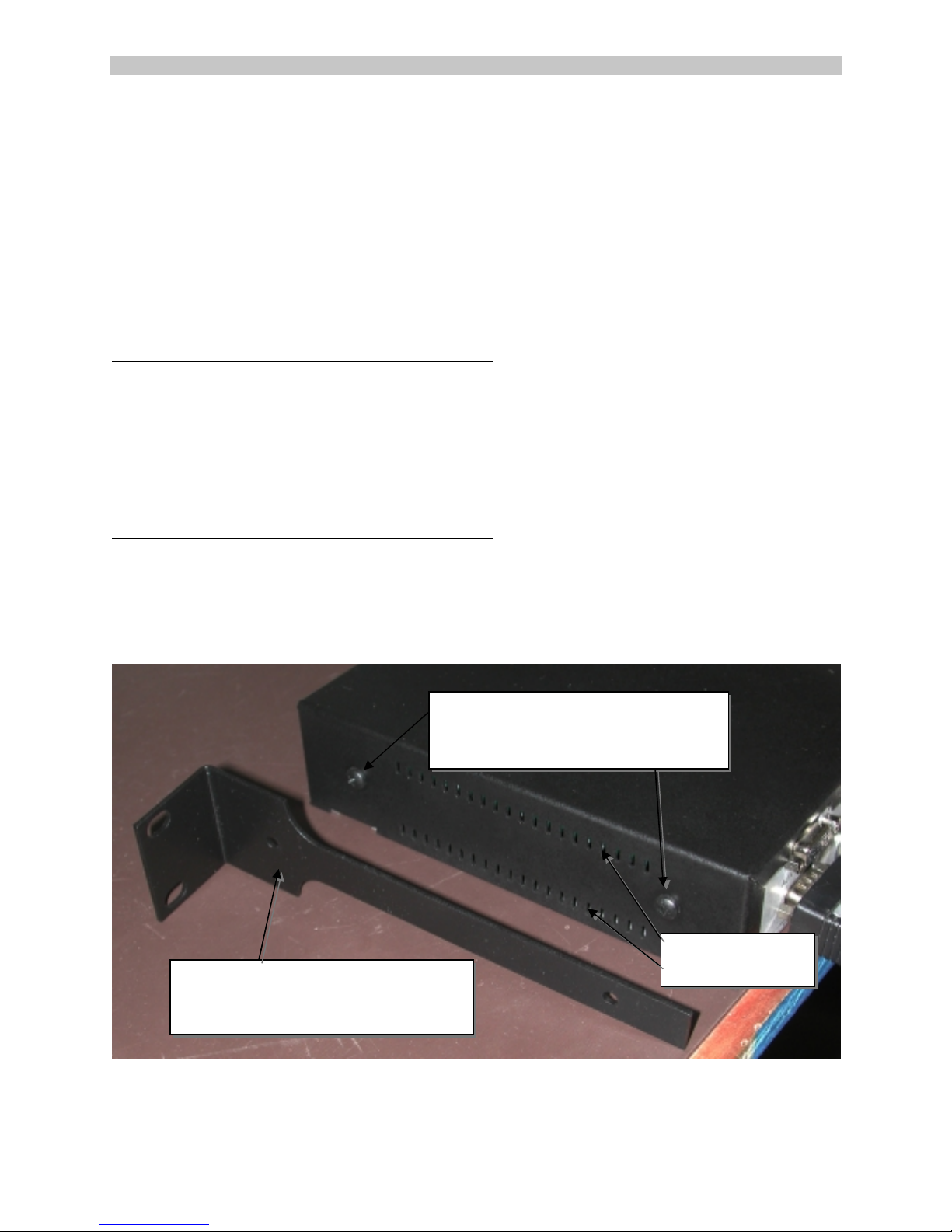
2.2 Rack Mount
The PC Fiberlynx units may be rack-mounted in a conventional 19-inch equipment rack. If rack
mounting, the user must install the rack mounting brackets (provided in the box with the unit)
and properly secure the unit in their rack. The PC Fiberlynx mounts from the front flanges only
(no rear support is required) using screws from your rack's manufacturer. If rack mounting, the
rubber feet included with the PC Fiberlynx are not required.
Remove these two screws
Place screws through holes in
Bracket and then retighten
Vent Louvers
Rack Mount Bracket
Secures with 2 screws
Brackets are same on both sides
Do Not Block
2-2 www.lightwavecom.com
Page 9

A Lantronix Company PC Fiberlynx User Guide
If rack-mounting the PC Fiberlynx system, the following considerations may apply:
PC Fiberlynx User Guide
PC Fiberlynx User GuidePC Fiberlynx User Guide
Elevated Operating Ambient Temperature
If installed in a closed or multi-unit rack assembly, the operating ambient temperature of the
rack environment may be greater than the room ambient temperature. Consideration should be
given to installing the equipment in an environment compatible with the maximum rated ambient
temperature.
Reduced Air Flow
Be sure that adequate airflow is allowed in the cabinet or enclosure, and that the louver vents
on either side of the PC Fiberlynx chassis are not blocked.
Mechanical Loading
Mounting of the equipment in the rack should be such that a hazardous condition is not
achieved due to uneven mechanical loading. Dress the cables to prevent undue pulling or
weight, as the chassis is normally mounted from the front (for flush appearance) while the
cables are attached from the rear of the chassis.
Circuit Overloading
Consideration should be given to the connection of the equipment to the supply circuit and the
effect that overloading might have on overcurrent protection and supply wiring. Appropriate
consideration of equipment nameplate ratings should be used when addressing this concern.
Reliable Earthing
Reliable earthing of rack-mounted equipment should be maintained. Particular attention should
be given to supply connection other than direct connections to the branch circuit (e.g., use of
power strips).
2.3 Site Preparation
1. Shutdown the CPU and disconnect the user peripherals (keyboard, mouse, monitor,
etc.).
2. Move the CPU and the user devices to their respective operating locations. Run a 6strand fiber optic cable with ST connectors between the CPU location and user station.
Fiber optic cable is available in custom and standard lengths from Lightwave
Communications.
3. Provide power connections for the PCFiberlynx units at each location, as well as power
for the CPU and any powered user peripherals (such as a monitor and speakers). The
PCFiberlynx uses a universal power supply.
15.00.034 Rev. C 2-3
Page 10

PC Fiberlynx User Guide
g
PC Fiberlynx User Guide Lightwave Communications
PC Fiberlynx User Guide PC Fiberlynx User Guide
Lightwave Communications
Lightwave CommunicationsLightwave Communications
The PC/SUN models of PC Fiberlynx (part numbers 200.100.01xx) are similar to the PC-only
version (part numbers 200.100.02xx). The difference is the SUN keyboard and mouse
connection is made using a single MiniDIN-8 cable, rather than two PS/2 cables. All other
devices and peripheral connections are the similar to the PC-only models.
SUN Keyboard/Mouse Connector
The PC Fiberlynx for PC/SUN Receiver is shown above. The PC/SUN Transmitter is similar.
2.4 Connecting Fiber Optic Cable
1. Situate the transmitter and receiver units close to their final locations. Run the fiber optic
cable to these locations with enough slack to prevent strain from damaging the cable.
2. Attach the individual fiber strands to the ST connectors on the back of each unit. Each
strand on the transmitter end should be attached to the same connector as on the
receiver end (i.e., red to red, blue to blue, etc.). Try to use the strand with the color
indicated on the connector; note any substitutions to avoid confusion.
Dress Cables to prevent kinks and tangles
Fiber Cables can be dama
ed if kinked or crushed.
3. Use the provided strain relief device to prevent damage to the fiber optic cable. The
strain relief ties may be trimmed if desired. When placing the transmitter and receiver in
the final location, be sure to allow sufficient space behind each unit to prevent excessive
bending of the fiber.
2-4 www.lightwavecom.com
Page 11
A Lantronix Company PC Fiberlynx User Guide
PC Fiberlynx User Guide
PC Fiberlynx User GuidePC Fiberlynx User Guide
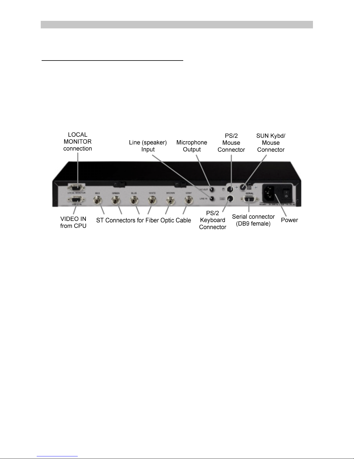
2.5 Connecting the CPU
Connecting the PC Fiberlynx is simple as it uses industry-standard connectors for each end of
the connection: at the CPU end, and at the remote or User end. Both models of PC Fiberlynx
will connect in a similar fashion at both ends; the only difference is that the PC/SUN model has
connections for both PC (PS/2) and SUN computers and keyboard and mice.
The PS/2 Only model does not have a SUN Keyboard and Mouse connector.
SUN / PC model
PCFiberlynx (SUN/PC) transmitter
1. Place the CPU with the PCFiberlynx transmitter. Connect the keyboard and mouse ports
of the CPU to the keyboard and mouse ports of the PCFiberlynx transmitter using the
two 6-pin mini-DIN cables (PS/2), or using the one mini-DIN8 cable (SUN).
2. Connect the video output of the CPU to the lower video connector of the transmitter
using the provided HD15 (VGA) cable. A monitor may be attached to the upper video
connector to view the video output of the CPU locally.
3. Connect the CPU audio ports to the transmitter using the provided 3.5 mm audio cables.
The port marked “MIC OUT” on the transmitter connects to the microphone port on the
CPU, while the “LINE IN” port on the transmitter connects to the speaker port on the
CPU.
4. Connect the CPU serial port to the transmitter serial port using the provided cable.
5. Connect the transmitter to AC power and turn on the switch. The status LEDs found on
the front of the unit should light.
15.00.034 Rev. C 2-5
Page 12

PC Fiberlynx User Guide
PC Fiberlynx User Guide Lightwave Communications
PC Fiberlynx User Guide PC Fiberlynx User Guide
Lightwave Communications
Lightwave CommunicationsLightwave Communications
PS/2-Only model
PCFiberlynx (PS/2 Only) transmitter
1. Place the CPU with the PCFiberlynx transmitter. Connect the keyboard and mouse ports
of the CPU to the keyboard and mouse ports of the PCFiberlynx transmitter using the
provided 6 pin mini-DIN cables.
2. Connect the video output of the CPU to the lower video connector (VIDEO IN) of the
transmitter using the provided HD15 (VGA) cable. A monitor may be attached to the
upper video connector to view the video output of the CPU locally.
3. Connect the CPU audio ports to the transmitter using the provided 3.5 mm audio cables.
The port marked “MIC OUT” on the transmitter connects to the microphone port on the
CPU, while the “LINE IN” port on the transmitter connects to the speaker port on the
CPU.
4. Connect the CPU serial port to the transmitter serial port using the provided cable.
5. Connect the transmitter to AC power and turn on the switch. The status LEDs found on
the front of the unit should light.
2-6 www.lightwavecom.com
Page 13

A Lantronix Company PC Fiberlynx User Guide
PC Fiberlynx User Guide
PC Fiberlynx User GuidePC Fiberlynx User Guide
2.6 Connecting the User Peripherals
Like the Transmitter end, both models of PC Fiberlynx receiver will connect in a similar fashion;
the only difference is that the PC/SUN model has connections for both PC (PS/2) and SUN
computers and keyboard and mice. The PS/2 Only model does not have a SUN Keyboard and
Mouse connector; it is shown below.
PCFiberlynx (PS/2 Only) receiver
1. Place the PCFiberlynx receiver on or near the user station. Connect the keyboard and
mouse to the proper ports on the receiver. If using the SUN keyboard and mouse, the
SUN keyboard is connected to the mini-DIN8 connector, and the mouse connects to the
Keyboard.
2. Connect the monitor to the receiver: the lower HD15 (VIDEO OUT) connector is the
primary video connector. The upper HD15 connector is for an auxiliary monitor; this
monitor will show identical information as the primary monitor.
3. Connect the audio devices to the receiver. The lower connector, marked “MIC IN”, is for
use with a microphone only. The upper connector, marked “LINE OUT”, is for connection
to powered speakers or headphones.
4. Connect the serial device to the receiver. The receiver’s serial port behaves like the DB9
serial port found on the back of a PC, and will connect to any device that would normally
connect to a PC.
5. Connect the receiver to AC power and turn on the switch. The status LEDs found on the
front of the unit should light.
15.00.034 Rev. C 2-7
Page 14

PC Fiberlynx User Guide
PC Fiberlynx User Guide Lightwave Communications
PC Fiberlynx User Guide PC Fiberlynx User Guide
Lightwave Communications
Lightwave CommunicationsLightwave Communications
2.7 Auxiliary Monitors
The PC Fiberlynx installation supports a total of three monitors when installed. All monitors will
have the same video information displayed. The VIDEO OUT on the PC Fiberlynx Receiver is
the Primary Video device. The video signal is determined by the settings established by your
video card for the monitor connected to the VIDEO OUT connector.
Your application may require an auxiliary monitor at the user end, and one is supported using
the AUX VIDEO OUT jack (HD15 female) on the PC Fiberlynx Receiver.
If a local monitor is desired near the CPU, a monitor may be connected to the LOCAL
MONITOR connector (HD15 female) on the PC Fiberlynx Transmitter.
2.8 Power Up Sequence
The Power-Up Sequence of the system is relatively simple: make sure all of the connections are
intact, and turn your CPU on last.
Video Record
Your CPU may or may not be concerned with the video connection, depending on the type of
video card you are employing. In some cases, a 'video record' is established between the
video card and the primary monitor during power up (or reboot), which determines the operating
characteristics of the video output. If this is the case, you must follow this order of events.
Assuming that the components are installed, but your computer, the monitor and both PC
Fiberlynx units are turned off:
1. Turn on the Monitor connected to VIDEO OUT on the Receiver.
2. Turn on the PC Fiberlynx Receiver (near the user end).
3. Turn on the PC Fiberlynx Transmitter (near the CPU).
4. Turn on the CPU. Allow the system to boot and establish the video record.
5. Turn on any other installed Monitors after a video signal is established at the remote
end.
The CPU will establish the 'video record', if your video card requires this, from the Monitor
connected to the VIDEO OUT connector on the PC Fiberlynx Receiver. If no monitor is
connected to the VIDEO OUT connector but a monitor is connected to the LOCAL MONITOR
connector of the PC Fiberlynx Transmitter, the video record can be established using that
monitor (e.g., during installation). So long as the CPU is not rebooted and the connections are
not broken, the video record information is maintained and will support the monitor when
connected to the VIDEO OUT connector.
2-8 www.lightwavecom.com
Page 15

A Lantronix Company PC Fiberlynx User Guide
PC Fiberlynx User Guide
PC Fiberlynx User GuidePC Fiberlynx User Guide
3: Operation
Once the CPU is operating, the PCFiberlynx will be transparent to the user. It will appear as
though the user peripherals are directly attached to the CPU.
Both the transmitter and receiver may be powered off while the CPU is on, without causing a
'break' signal to be received by the CPU which may cause it to lock up. As long as all cables
remain connected between the CPU and transmitter, the CPU will continue to operate without
error due to hardware disconnection.
If there is no signal to the receiver (e.g., if the transmitter has no power or the fiber optic cable is
broken or disconnected), the three keyboard status lights (Num Lock, Caps Lock, and Scroll
Lock) will flash together.
3.1 Video Resolution
The PCFiberlynx supports resolutions from 640x480 to 1280x1024.
3.2 Front Panel LEDs
The front panel LEDs indicate status of the PCFiberlynx. The transmitter and receiver lights
indicate status as marked on the front panel. The tables below outline the light status and
possible solutions to the status abnormalities. Note that any flashing or blinking LEDs will not
flash in step; all LEDs will flash at separate rates.
Transmitter Unit
label
appearance status action
TxD blinking
green
solid green unit not transmitting
normal
• cycle power
data
15.00.034 Rev. C 3-9
Page 16

PC Fiberlynx User Guide
PC Fiberlynx User Guide Lightwave Communications
PC Fiberlynx User Guide PC Fiberlynx User Guide
Lightwave Communications
Lightwave CommunicationsLightwave Communications
label appearance status action
RxD blinking
normal
green
solid red or
orange
Master
Sync
blinking
green
solid red incorrect video sync
not receiving data
• check fiber connections
• cycle power on both units
normal
• check video sync format and
format
change to separate horizontal
and vertical
• check video input connection
• make sure “Video In”
connector is used
Video B solid green normal
unlit not receiving proper
video signal
• check that the CPU is on
• check that the CPU is not in
suspend/power saver mode
• check video input connection
and cable
Video G solid green normal
unlit not receiving proper
video signal
• check that the CPU is on
• check that the CPU is not in
suspend/power saver mode
• check video input connection
and cable
Video R solid green normal
unlit not receiving proper
video signal
• check that the CPU is on
• check that the CPU is not in
suspend/power saver mode
• check video input connection
and cable
H Sync blinking
green
normal
• if only H Sync light is flashing,
sync may be composite
format
unlit or solid
green
improper sync signal
or no sync signal
• check sync format
• check video input connection
and cable
V Sync blinking
green
normal
• if only H Sync light is flashing,
sync may be composite
format
solid green improper sync signal
• signal may be composite or H
sync only – check format at
CPU
unlit no sync signal
• check sync format
• check video input connection
and cable
3-10 www.lightwavecom.com
Page 17

A Lantronix Company PC Fiberlynx User Guide
PC Fiberlynx User Guide
PC Fiberlynx User GuidePC Fiberlynx User Guide
Receiver Unit
label
appearance status action
TxD blinking
normal
green
solid green unit not transmitting
• cycle power
data
RxD blinking
normal
green
solid red or
orange
Master
Sync
blinking
green
solid red or
orange
Video B
off normal
not receiving data
• check fiber connections
• cycle power on both units
normal
not receiving sync
data
• check fiber connections
• cycle power
left LED
solid red /
solid green
adjusting coarse
gain / adjusting fine
gain
normal at start
if constantly adjusting:
• check fiber connection
marked “BLUE”
• check fiber distance between
stations
• check video source
Video B
right LED
red or
blinking
green
orange
normal
high gain mode
• check fiber connection
marked “BLUE”
• check fiber distance between
stations
Video G
off normal
left LED
solid red /
solid green
adjusting coarse
gain / adjusting fine
gain
normal at start
if constantly adjusting:
• check fiber connection
marked “GREEN”
• check fiber distance between
stations
• check video source
Video G
right LED
blinking
green
normal
15.00.034 Rev. C 3-11
Page 18

PC Fiberlynx User Guide
PC Fiberlynx User Guide Lightwave Communications
PC Fiberlynx User Guide PC Fiberlynx User Guide
Lightwave Communications
Lightwave CommunicationsLightwave Communications
label appearance status action
red or
orange
high gain mode
• check fiber connection
marked “GREEN”
• check fiber distance between
stations
Video R
off normal
left LED
solid red /
solid green
adjusting coarse
gain / adjusting fine
gain
normal at start
if constantly adjusting:
• check fiber connection
marked “RED”
• check fiber distance between
stations
• check video source
Video R
right LED
red or
blinking
green
orange
normal
high gain mode
• check fiber connection
marked “RED”
• check fiber distance between
stations
H Sync blinking
green
normal
• if only H Sync light is
flashing, sync may be
composite format
unlit improper sync signal
• check sync format
• check video input connection
V Sync blinking
green
normal
• if only H Sync light is
flashing, sync may be
composite format
unlit improper sync signal
• check sync format
• check video input connection
3-12 www.lightwavecom.com
Page 19

A Lantronix Company PC Fiberlynx User Guide
PC Fiberlynx User Guide
PC Fiberlynx User GuidePC Fiberlynx User Guide
4: Appendix A Serial Port Pinouts
Transmitter Serial Connector Receiver Serial Connector
4
9 8 6
23
7
DB9 Female
Serial Input
RS-232
DB9F
3
2
7
8
4
6
Tx
Rx
RTS
CTS
DTR
DSR
15
2
6 7 9
43
8
51
DB9 Male
Serial Output
RS-232
DB9M
Tx
Rx
RTS
CTS
DTR
DSR
3
2
7
8
4
6
1
9
5
15.00.034 Rev. C 4-13
DCD
RI
SG
1 - Data Carrier Detect (DCD)
2 - Receive Data (RxD)
3 - Transmit Data (TxD)
4 - Data Terminal Ready (DTR)
5 - Signal Ground (GND)
6 - Data Set Ready (DSR)
7 - Ready To Send (RTS)
8 - Clear To Send (CTS)
9 - Ring Indicator (RI)
DCD
RI
SG
1
9
5
Page 20

PC Fiberlynx User Guide
PC Fiberlynx User Guide Lightwave Communications
PC Fiberlynx User Guide PC Fiberlynx User Guide
Lightwave Communications
Lightwave CommunicationsLightwave Communications
5: Appendix B Specifications
B.1 Physical
Width: 16.25 inches (41.2 cm)
Depth: 6.875 inches (7.5 cm)
Height: 1.75 inches (4.4 cm)
Shipping weight: 20 pounds (9.1 kg)
B.2 Environmental
Operating temperature: 32°F (0°C) to 122°F (50°C)
Operating humidity: 10% to 90% RH, non-condensing
Storage temperature: -4°F (-20°C) to 161°F (70°C)
Storage humidity: 10% to 90% RH, non-condensing
B.3 Electrical
Universal AC input, auto-switching
110/220 VAC 50/60 Hz ~1.0A
IEC-type power input connector. Cordset provided with system.
B.4 Optical
B.4.1 LEDs and Detectors
Wavelength: 850 nm
Loss budget: 7 dB
B.4.2 Fiber Optic Cable
Recommended cable: FDDI-grade six strand
Maximum length: 3,310 feet (1000 meters)
5-14 www.lightwavecom.com
Page 21

A Lantronix Company PC Fiberlynx User Guide
PC Fiberlynx User Guide
PC Fiberlynx User GuidePC Fiberlynx User Guide
B.5 Interface
B.5.1 Video
Connector: HD15 female (VGA)
Sync format: separate horizontal and vertical
Maximum resolution: 1280 x 1024
B.5.2 Keyboard and Mouse
Connector: 6-pin mini-DIN
Format: PS/2
B.5.3 Serial
Transmitter Connector: DB9 female
Receiver Connector: DB9 male
Specification: EIA-232
Maximum baud rate: 38,400
B.5.4 Audio
Connector: 3.5 mm stereo jack
Line output impedance: 220 Ω use powered speakers only
Microphone impedance: 1 kΩ
B.6 Compliance and Certification
Entela Electrical Safety Certification (equivalent to UL 1950 and CSA 950)
Entela is a USA OSHA Nationally Recognized Testing Laboratory (NRTL), an accredited
Certification Organization by the Standards Council of Canada (SCC), and an IECEE – CB
Scheme National Certification Body (NCB) & Certification Body Testing Laboratory (CBTL).
CE certification
Conforms to FCC part 15, Class A
15.00.034 Rev. C 5-15
 Loading...