

User Manual (Hardware)
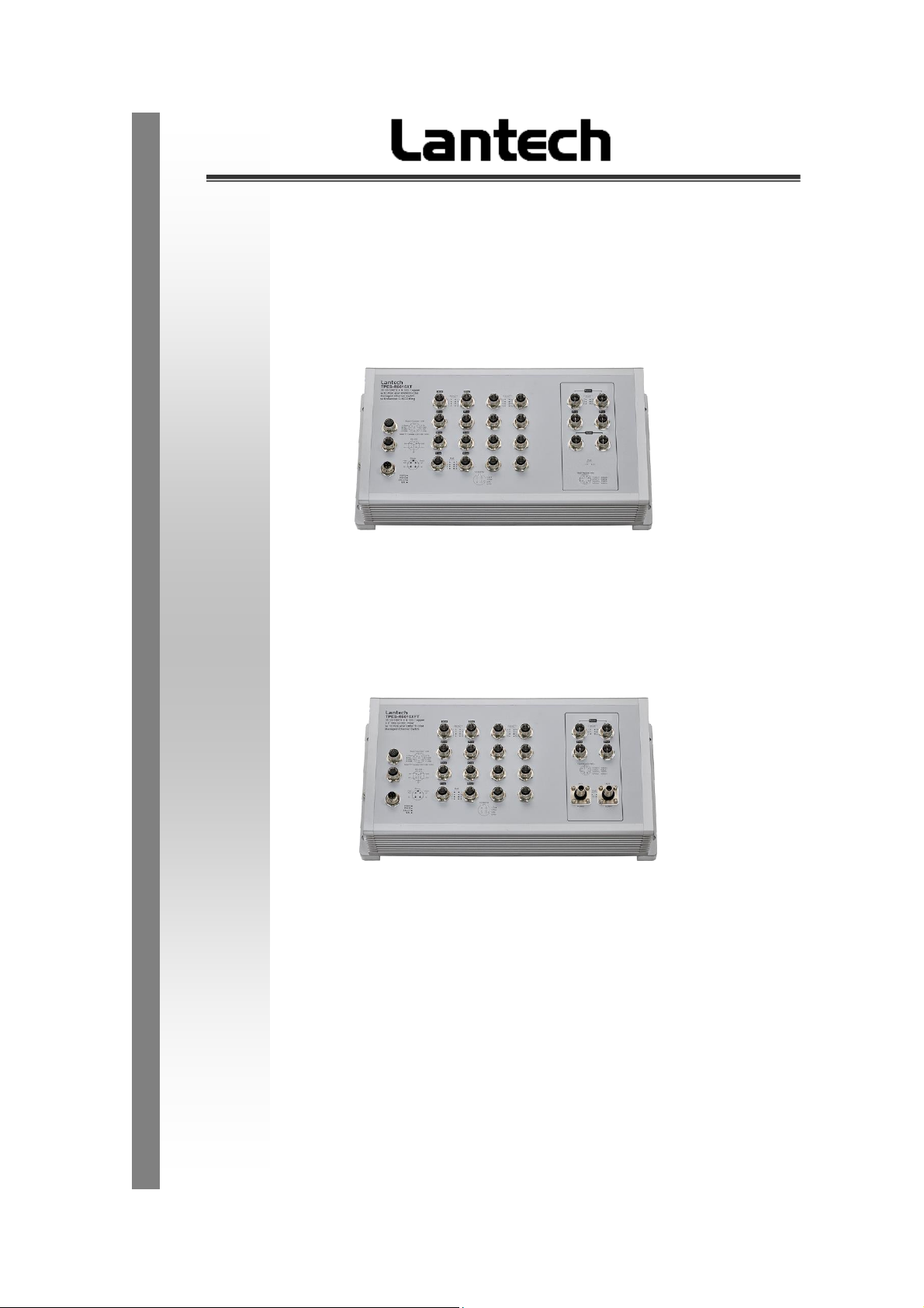
T(P)ES-R6616XFT
16 10/100TX + 4 10G Copper + 2 10G SR Fiber Q-ODC (w/ PoE at/af)
EN50155 OS4 Managed Ethernet Switch
T(P)ES-R6616XT
16 10/100TX + 6 10G Copper (w/ PoE at/af) EN50155 OS4 Managed
Ethernet Switch
Nov. 2019
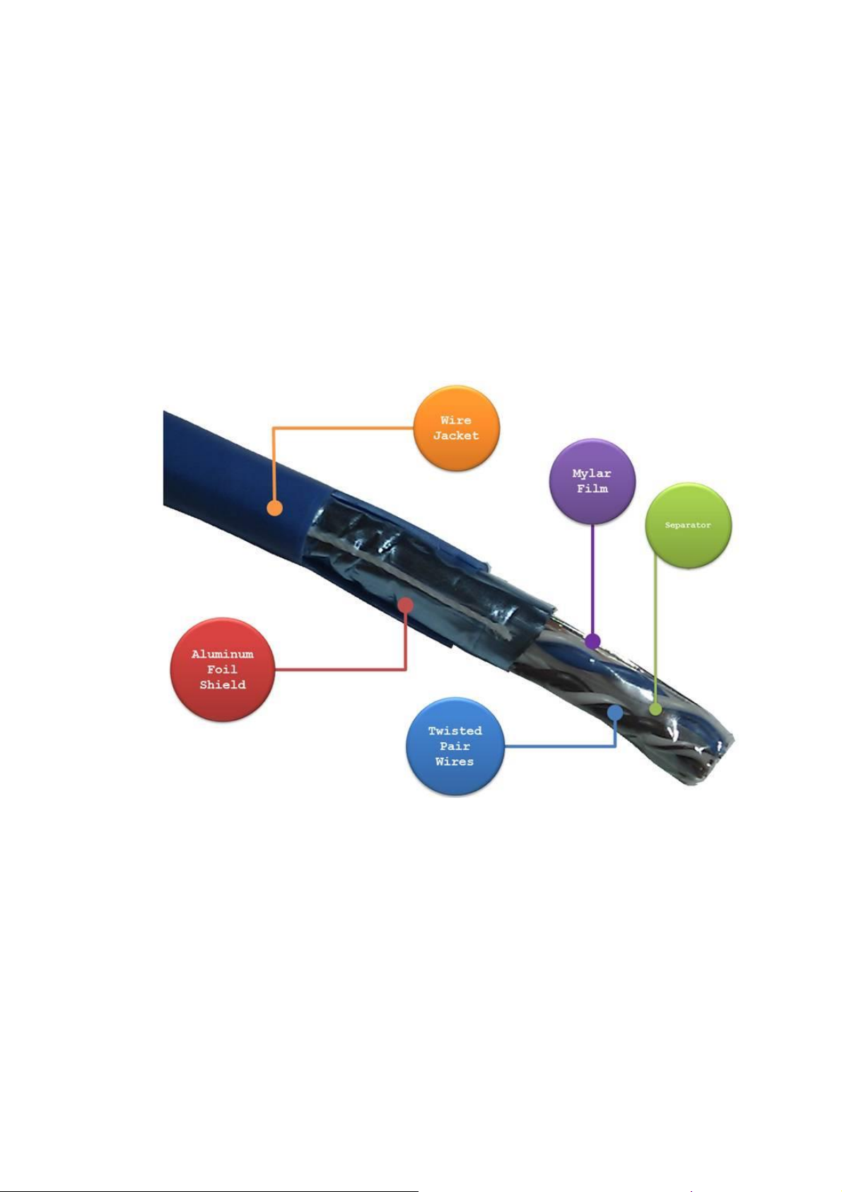
Recommendation for Shielded network cables
STP cables have additional shielding material that is used to reduce external interference.
The shield also reduces emissions at any point in the path of the cable. Our
recommendation is to deploy an STP network cable in demanding electrical environments.
Examples of demanding indoor environments are where the network cable is located in
parallel with electrical mains supply cables or where large inductive loads such as motors
or contactors are in close vicinity to the camera or its cable. It is also mandatory to use an
STP cable where a power device (like an IP camera) is used outdoors or where the
network cable is routed outdoors.

Important Notice
Lantech Communications Global, Inc. reserves the right to modify the
equipment, its specification or this manual without prior notice, in the interest
of improving performance, reliability, or servicing. At the time of publication
all data is correct for the operation of the equipment at the voltage and/or
temperature referred to. Performance data indicates typical values related to
the particular product.
No part of this documentation or information supplied may be divulged to any
third party without the express written consent of Lantech Communications
Global Inc. Products offered may contain software which is proprietary to
Lantech Communications Global Inc. The offer or supply of these products
and services does not include or infer any transfer of ownership.
Interference Issues
This Equipment has been tested and has been found to comply with the
limits for a Class A digital device, pursuant to Part 15 of the FCC rules.
These limits are designed to provide reasonable protection against harmful
interference in a commercial or industrial installation. This equipment
generates, uses, and can radiate radio frequency energy. It may cause
harmful interference to radio communications if the equipment is not installed
and used in accordance with the instructions.

FCC Warning
This Equipment has been tested and found to comply with the limits for a
Class-A digital device, pursuant to Part 15 of the FCC rules. These limits
are designed to provide reasonable protection against harmful interference
in a residential installation. This equipment generates, uses, and can
radiate radio frequency energy. It may cause harmful interference to radio
communications if the equipment is not installed and used in accordance
with the instructions. However, there is no guarantee that interference will
not occur in a particular installation. If this equipment does cause harmful
interference to radio or television reception, which can be determined by
turning the equipment off and on, the user is encouraged to try to correct
the interference by one or more of the following measures:
Reorient or relocate the receiving antenna.
Increase the separation between the equipment and receiver.
Connect the equipment into an outlet on a circuit different from that to
which the receiver is connected.
Consult the dealer or an experienced radio/TV technician for help.
CE Mark Warning
This is a Class-A product. In a domestic environment this product may
cause radio interference in which case the user may be required to take
adequate measures.

Content
Chapter 1 Hardware Description............................ 5
1.1 Physical Dimension .................................... 5
1.2 Package Content: ........................................ 6
1.3 IP Protection ................................................ 7
1.4 LED Indicators............................................10
1.5 Bypass design............................................11
Charter 2. Hardware Installation ............................ 13
2.1 Wall mount installation ..............................13
Chapter 3 Connect Cable ..................................... 16
3.1 Power input M12 connector. .....................16
3.2 Console & USB dongle M12 connector ....18
3.3 10/100Tx interface M12 connector ............19
3.4 10G interface M12 connector ....................21
3.5 Fiber interface Q-ODC connector .............22
3.6 Ground interface M6 connector ................23
Chapter 4 Maintenance......................................... 24
Chapter 5 Console Management.......................... 25
5.1 Connecting to the Console Port ................25
5.2 Login in to the Console Interface ..............25
Chapter 1 Hardware Description
Lantech T(P)ES-R6616XFT / T(P)ES-R6616XT are high performance OS4 EN50155
10G uplink Ethernet switches with 16 10/100TX (with up to 16 PoE at/af injectors) by
M12 connectors which provides L2 wire speed and advanced security function for
connecting PD network.
In this paragraph, it will describe the Industrial switch’s hardware spec, port, cabling
information, and wiring installation.
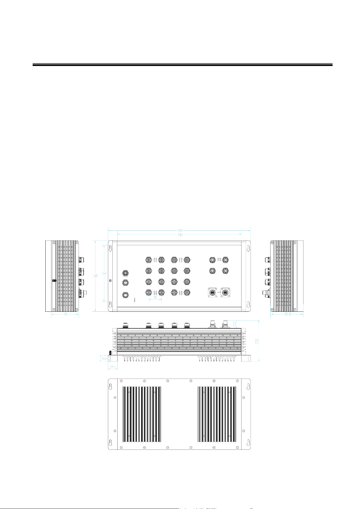
1.1 Physical Dimension
T(P)ES-R6616XFT
Aluminum case. IP-21,
390 (W) x 195 (D) x 112 (H) mm
5
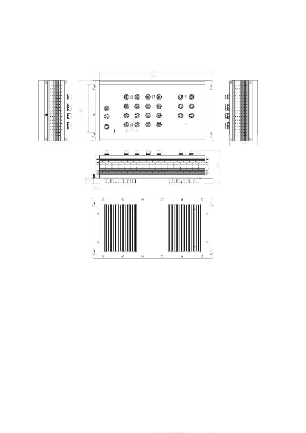
T(P)ES-R6616XT
Aluminum case. IP-21,
390 (W) x 195 (D) x 105.3 (H) mm
1.2 Package Content:
Product
Console cable
6

Level
Object size
protected against
Effective against
0
—
No protection against contact and ingress of objects
1
>50 mm
Any large surface of the body, such as the back of a
hand, but no protection against deliberate contact
with a body part
2
>12.5 mm
Fingers or similar objects
3
>2.5 mm
Tools, thick wires, etc.
4
>1 mm
Most wires, screws, etc.
5
Dust protected
Ingress of dust is not entirely prevented, but it must
not enter in sufficient quantity to interfere with the
satisfactory operation of the equipment; complete
protection against contact
6
Dust tight
No ingress of dust; complete protection against
contact
1.3 IP Protection
The IP Code, Ingress Protection Rating, sometimes also interpreted as International
Protection Rating, classifies and rates the degree of protection provided against the
intrusion (including body parts such as hands and fingers), dust, accidental contact, and
water in mechanical casings and with electrical enclosures. It is published by the
International Electrotechnical Commission (IEC)
Solid particle protection
The first digit indicates the level of protection that the enclosure provides against access
to hazardous parts (e.g., electrical conductors, moving parts) and the ingress of solid
foreign objects.
7

Level
Protected
against
Testing for
Details
0
Not
protected
—
—
1
Dripping
water
Dripping water (vertically
falling drops) shall have no
harmful effect.
Test duration: 10 minutes
Water equivalent to 1 mm
rainfall per minute
2
Dripping
water when
tilted up to
15°
Vertically dripping water
shall have no harmful effect
when the enclosure is tilted
at an angle up to 15° from
its normal position.
Test duration: 10 minutes
Water equivalent to 3 mm
rainfall per minute
3
Spraying
water
Water falling as a spray at
any angle up to 60° from
the vertical shall have no
harmful effect.
Test duration: 5 minutes
Water volume: 0.7 litres per
minute
Pressure: 80–100 kPa
4
Splashing
of water
Water splashing against
the enclosure from any
direction shall have no
harmful effect.
Test duration: 5 minutes
Water volume: 10 litres per
minute
Pressure: 80–100 kPa
5
Water jets
Water projected by a
nozzle (6.3 mm) against
enclosure from any
direction shall have no
harmful effects.
Test duration: at least
15 minutes
Water volume: 12.5 litres per
minute
Pressure: 30 kPa at distance
of 3 m
Liquid ingress protection
The second digit indicates the level of protection that the enclosure provides against
harmful ingress of water.
8

6
Powerful
water jets
Water projected in powerful
jets (12.5 mm nozzle)
against the enclosure from
any direction shall have no
harmful effects.
Test duration: at least
3 minutes
Water volume: 100 litres per
minute
Pressure: 100 kPa at
distance of 3 m
7
Immersion
up to 1 m
Ingress of water in harmful
quantity shall not be
possible when the
enclosure is immersed in
water under defined
conditions of pressure and
time (up to 1 m of
submersion).
Test duration: 30 minutes
Immersion at depth of at
least 1 m measured at
bottom of device, and at least
15 cm measured at top of
device
8
Immersion
beyond 1 m
The equipment is suitable
for continuous immersion in
water under conditions
which shall be specified by
the manufacturer.
Normally, this will mean
that the equipment is
hermetically sealed.
However, with certain types
of equipment, it can mean
that water can enter but
only in such a manner that
it produces no harmful
effects.
Test duration: continuous
immersion in water
Depth specified by
manufacturer
9
Powerful
high
temperature
water jets
Protected against closerange high pressure, high
temperature spray downs.
—
9

LED
Color
Status
Meaning
R.M
Green
On
The switch unit is owner switch of ITURing
Off
The switch is not owner switch
PWR1
Green
On
Power 1 is active
Off
Power 1 is inactive
PWR2
Green
On
Power 2 is active
Off
Power 2 is inactive
FAULT
Red
On
Power or port failure
Off
No failure
P1 ~ P16
Link/Act
Green
On
A network device is detected.
Blinking
The port is transmitting or receiving
packets from the TX device.
Off
No device attached
P17 ~ P22
(R6616XT)
Link/Act
P17 ~ P20
(R6616XFT)
Link/Act
Yellow /
Orange
On(Yellow)
A network device with 1G/2.5G/5G
interface is detected.
On(Orange)
A network device with 10G copper
interface is detected.
Blinking
The port is transmitting or receiving
packets from the TX device
Off
No device attached
1.4 LED Indicators
The diagnostic LEDs that provide real-time information of system and optional status are
located on the front panel of the industrial switch. The following table provides the
description of the LED status and their meanings for the switch.
10

P21&P22
(R6616XFT)
Link/Act
Orange
On
A network device is detected.
Off
No device attached
Notification: P21&P22 ports are designed with 10G fiber interface and extend from
CPU, not PHY chipset. So both these ports don’t support blinking status when data is
forwarding via port21 or port22 or both.
PoE
(TPES-R6616XFT & TPESR6616XT)
On
The port is operating in PoE mode.
Off
The port is not operating in PoE mode.
1.5 Bypass design
(Available on -BT/-BBT/-BF/-BBT-BF models)
The bypass module is like an alarm relay but it has default position – close. When
system finish booting procedures, CPU will ask bypass module change position from
close to open and keep in open status. That’s why when switch loss the power, bypass
module will be active, because CPU has no ability to ask bypass module keep in open
status then bypass will be restored to default position – close.
There is another condition will trigger bypass module -- CPU hang. When CPU is hang,
it also loss ability to ask bypass module keep in open status. But at this time, watch dog
chipset will force to reset CPU then system will reboot. The CPU will back to normal
status after rebooting then ask bypass module to keep in open status.
Bypass mechanism in open status
11

Bypass mechanism in close status
12

Charter 2. Hardware Installation
There are no mechanically active moving parts in the switch, to fix the switch into an
installation position, please use M4 size screw and corresponding nut and standard M4
screwdriver to install switch in the field.
2.1 Wall mount installation
1. Please make sure the screw diameter is M4.
2. Check all 4 fix holes on the switch and find corresponding position in the wall .Use
the appropriate tool to drill 4 holes onto the corresponding position, make sure the
diameter of holes is compatible with the M4 screws, fix the 4 screws into these 4
holes but don’t screw tightly, in order to have enough space to mount the switch.
3. Mount switch in wall with 4 fixed screws.
13

4. Attach switch in wall with 4 screws
5. Move down
6. Tighten 4 screws
14

15

Chapter 3 Connect Cable
After the hardware installation is complete, please connect the cable to the switch. All the
external interfaces use M12 connector design and follow IEC 61076 standard except the for
the fiber interface with QODC connector. The M12 connector on the 10G copper interface
supports IEC 61076-2-109 standard, make sure the connector for the 10G cable also
supports this standard or it will reduce the Max throughput of the 10G copper interface.
3.1 Power input M12 connector.
Spec. of power input
Voltage of Power Input:
Dual DC input, 16.8VDC~137.5VDC
Total PoE budget: 80W
Please make sure that the external power supply unit can satisfy the total power
consumption in field.
Ping assignment of power input
Make sure the direction of connector is correct before you connect it.
16

Plug power connector and screw in clockwise direction to fix it.
17

3.2 Console & USB dongle M12 connector
Ping assignment of console & USB dongle
Note: The USB port is USB 2.0 speed, not USB 3.0
Make sure the connector is the right direction before you connect it.
Plug console connector and screw in clockwise direction to fix it.
18

3.3 10/100Tx interface M12 connector
(Port 1 – Port 16 on TPES-R6616XFT and TPES-R6616XT)
Ping assignment of the 10/100Tx port
19

Make sure the direction of connector is correct before you connect it.
Plug the 10/100Tx connector and screw in clockwise direction to fix it.
20

3.4 10G interface M12 connector
(Port 17 – Port 20 on TPES-R6616XFT and Port 17 – Port 22 on TPES-R6616XT)
Ping assignment of the 10G port
Make sure the direction of connector is correct before you connect it.
Plug 10G connector and screw in clockwise direction to fix it.
21

3.5 Fiber interface Q-ODC connector
(Port 21 – Port 22 on TPES-R6616XFT & TES-R6616XFT)
Make sure the direction of the connector is correct before you connect it.
Plug 10G connector and move in different directions to make sure the Q-ODC connector
is correctly connected with the interface.
22

3.6 Ground interface M6 connector
Ground
The chassis is grounded via a separate grounding nut (M6).
Use toothed locking washers for a good electrical connection.
23

Ground screw of the switch
Chapter 4 Maintenance
1 Check each switch connection and make sure they are all screwed correctly.
2 Keep the anti-dust cap on all un-used switch interface
3 Access switch via web browser and check the below points:
3.1 Compare the physical connection of the switch port with the switch icon on the web
user interface to make sure the connecting status match each other.
3.2 Check the information on the hardware monitor to make sure all conditions are in
normal status.
3.3 Check event log to see if there are any abnormal events.
24

Chapter 5 Console Management
5.1 Connecting to the Console Port
The supplied cable has one M12 4-pole connector end and another RS-232 connector
end. Attach the RS-232 connector end to a PC or terminal and the other M12 connector
end to the console port of the switch. The connected terminal or PC must support the
terminal emulation program.
5.2 Login in to the Console Interface
When the connection between Switch and PC is ready, turn on the PC and run a
terminal emulation program or Hyper Terminal and configure the communication
parameters to match the following default characteristics of the console port:
Baud Rate:115200 bps
Data Bits: 8
Parity: none
Stop Bit: 1
Flow control: None
25

The settings of communication parameters
Having finished setting up the parameters, click ‘OK’. When the blank screen shows up,
press the Enter key to have the login prompt appear. Key in ‘admin’ (default value) for
both User name and Password (use Enter key to switch), then press Enter and the Main
Menu of console management should appear. Please see below figure for login screen.
Console login interface
===============Notice===============
For web-based management, please refer to our “Software Management Manual”.
Please contact support@lantechcom.tw for more information.
26
 Loading...