


Lantech
LSC-1102B
SERIAL TO TCPIP CONVERTER
User Manual
V1.0
Sep 2016

Table of Contents
1. Introduction ……………………………………………… 3
Overview ……………………………………………………… 4
Product Specifications ………………………………………… 8
2. Description & Installation ……………………………… 10
Product Panel Views …………………………………………… 10
LED Indicators ………………………………………………… 12
Wiring Architecture …………………………………………… 13
RS-232 ………………………………………………………… 13
RS-422/RS-485 ………………………………………………… 13
3. Converter Configuration …………………………… 15
4. Setting Verification …………………………………… 32
Hyper Terminal for TCP/IP WinSock ……………………… 33
Hyper Terminal for COM Port ……………………………… 38
Data Transmission …………………………………………… 39
Appendix A - FAQ ………………………………………… 40
Appendix B - Pin Outs and Cable Wiring ………… 41
B.1 DC-In Jack ……………………………………………… 41
B.2 RJ-45 Pin Assignment …………………………………… 41
B.3 RS-232 Pin Assignment ………………………………… 41
B.4 RS-232 Wiring Diagram ………………………………… 42
B.5 RS-422 Pin Assignment ………………………………… 42
B.6 RS-422 Wiring Diagram ………………………………… 42
B.7 RS-485 Wiring Diagram ………………………………… 42
Appendix C Firmware Upgrade ……………………… 43

11
Introduction
Lantech LSC-1102B is a full set serial device within two serial ports as one is a
RS-232 port and other one is a 422/ 485 (Auto-Detective) and it provides one
socket connection port.
Lantech provides new ways of connecting legacy serial devices to a Local Area
Network (LAN) or Wide Area Network (WAN). TCP/IP serial devices are
designed to operate serial ports over 100Mbit/s Ethernet networks. The data is
transmitted via TCP/IP protocol. Therefore control is available via Ethernet,
Intranet and Internet. LSC-1102B serial device is packaged in a PVC material
case well suited for industrial environments. All serial ports operate in common
industrial configuration. The serial device can be configured as network server or
network client. In the client mode, it can be installed in network which is
protected by NAT router or firewall, without the need of a real IP address. The
firmware of LSC-1102B can be reprogrammed directly via Ethernet network to
keep up with latest network standards. Lantech LSC-1102B is one of the best
serial devices for industrial applications.

Serial Ports
Port
RS-232 * 1 Port ( DB9 ) , RS- 422 / 485 * 1 Port ( Auto Detect )
Speed
300 bps ~ 230.4 Kbps
Parity
None , Odd , Even , Mark , Space
Data Bit
5 , 6 , 7 , 8
Stop Bit
1 , 2
Port-1
RS-232 Pins : Rx , Tx , GND , RTS , CTS , DTR , DSR , DCD
Port-2 (RS-422)
Rx+ , Rx- , Tx+ , Tx- ( Surge Protect )
Port-2 (RS-485)
Data+ , Data- ( Surge Protect )
Resistor
Built–in RS-422 / RS-485 pull high / low Resistor
ESD
15KV ESD for all signal
Ethernet Port
Port Type
RJ-45 Connector
Speed
10 / 100 Mbps ( Auto Detect )
Protocol
ARP , IP , ICMP , UDP , TCP , HTTP , DHCP , TELNET
Mode
TCP Server / TCP Client / UDP / Virtual Com / Pairing
Setup
HTTP Browser Setup ( IE )
Security
Login Password
Protection
Built-in 1.5KV Magnetic Isolation
General Specification
CPU
32-bits ARM-Cortex-M4 CPU , 120 MHz
ROM
512K bytes Flash ROM
RAM
128K bytes SRAM
Digital I/O
Digital I/O * 16 TTL
Watch Dog Function
Present
IP Search Utility
Supports Win-7, Win-8 , Vista , Win-XP , Win-2003 server , Win-2000,
Win-10
Virtual COM
Supports Windows 2000 / 2003 / XP / Vista / Win-7 / Win-8 / Win-10
Firmware Update
Firmware On-line Updated Via Ethernet
LED
SYS ( PWR ) , DI/DO, Port2(RS-422/485), Port1(RS-232)
Power
DC 9 ~ 30 V , 300mA @ 12VDC
Operating Temperature
-10°C~70°C
Storage Temperature
-20°C~85°C
Installation
Din-Rail and Panel mounting options
Dimensions
90 x 60 x 25 mm ( W * D * H )
Weight
100g
EMC
FCC Class A, CE Class A
Warranty
2 years
Product Specifications
22
Converter Description & Installation
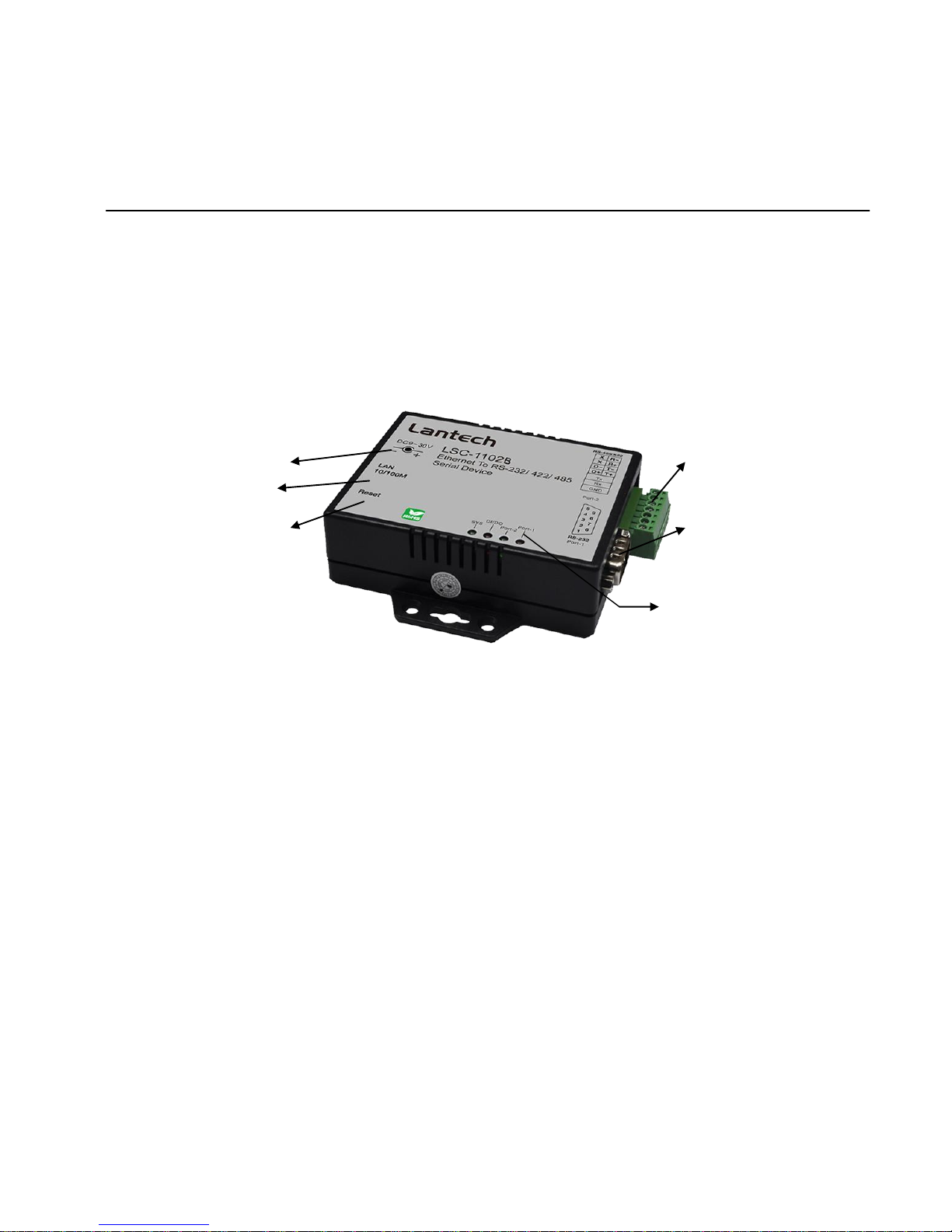
Product Panel Views
Serial I/O Port of RS-232 and RS-422/485
Connect the serial data cable between the converter device and the serial devices.
Follow the parameter setup procedures to configure the converter (see the following
chapters ).
Digital I/O
Transforming the sensor which connecting on the Lantech TCP/IP converters
equipment statuses into the TCP/IP package data and send out by the Ethernet
DataStream ( The Lantech TCP/IP converters must indicate the IP address and Com
Port) or activating the indicated Digital output (Remote WinSock must indicate the
DC-In
Power Outlet
Ethernet LAN Port
Serial I/O Port
RS-232
Serial I/O Port
RS-485/RS-422
LED Indicators
Reset Button

Lantech TCP/IP converters)Connect the data wires between the Lantech TCP/IP
converters and the RS-485/RS-422 device. Follow the parameter setup procedures to
configure the converter (see the following chapters).
Power Supply
LSC-1102B TCP/IP converter device is powered by a single 9Vdc (inner
positive/outer negative) power supply and 500mA of current. A suitable power supply
adapter is part of the packaging. Connect the power line to the power jack at the left
side of LSC-1102B TCP/IP converter device and put the adapter into the socket. If the
power is properly supplied, the “PWR” red color LED will be on..
Ethernet LAN Port
The connector for network is the usual RJ45. Simply connect it to your network
switch or Hub. When the connection is made, the LAN LED indicator will light.
When data traffic occurs on the network, red DATA LED indicator will blink during
data transferring and receiving.
Reset Button
If by any chance, you forget the setup password, or have incorrect settings making
Lantech TCP/IP converter inoperable. First, turn off the power. Second, use any point
tip to push this button and hold it to turn on the power at the same time for 5 second.
All the parameters will be reset to the factory default.
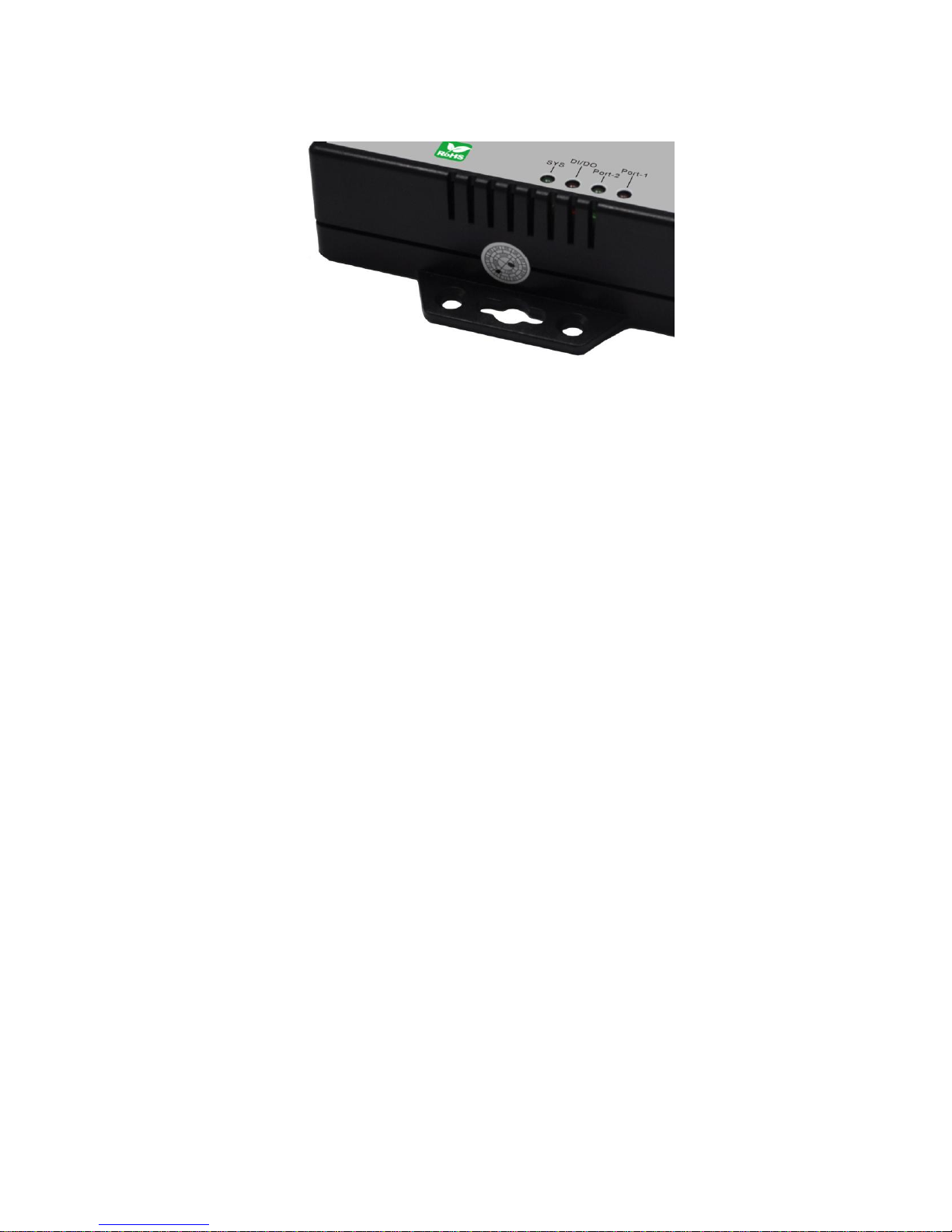
LED Indicators
PWR (Red):
It is a power indicator (When the power is on, the LED will be on.)
Tx (Green):
Data sent indicator (When data are sending to the network, the LED will blink.)
Rx (Red):
Data received indicator (When data are receiving to the network, the LED will blink.)
SYS (Green):
It is a device statues indicator (When Lantech TCP/IP converter is operated in normal
statues, the LED will blink once per second.)
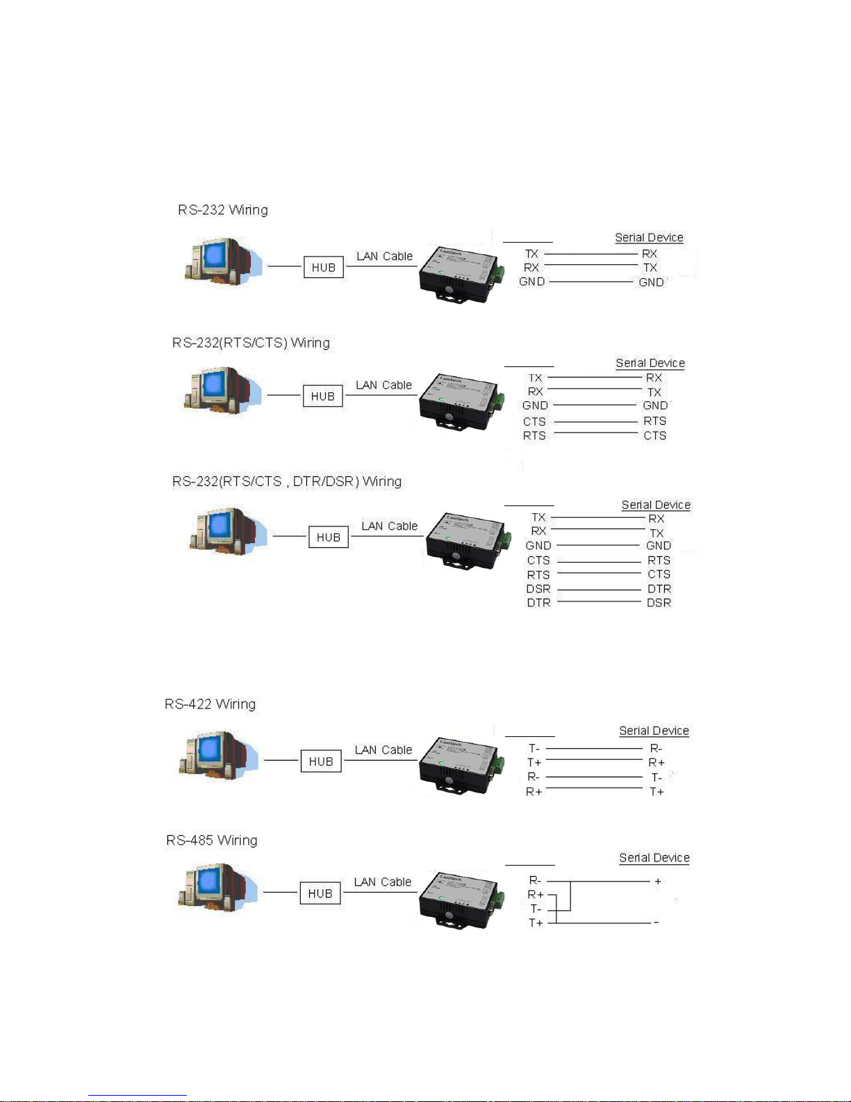
Wiring Architecture
RS-232 Wiring Architecture
RS-422/RS-485 Wiring Architecture
LSC-1102B
LSC-1102B
LSC-1102B
LSC-1102B
LSC-1102B

When you finish the steps mentioned above and the LED indicators are as shown, the
converter is installed correctly. You can use the Setup Tool “CVBrowser.exe” to setup the
IP Address.
To proceed the advanced parameter setup, please use a web browser (IE or Netscape) to
continue the detailed settings.

33
Converter Configuration
Software installation
1. Copy CVBrowser.EXE file from CD to your desktop .
2. Execute CVBrowser.EXE.

Hardware Installation
1. Connect LSC-1102B to your desktop directly or by switch.
2. Power on LSC-1102B
3. Click scope icon of CVBrowser to search the LSC-1102B(Default IP 192.168.0.100)
4. Make sure the IP of your desktop and LSC-1102B are in the same domain (192.168.0.x)

How to change the IP address of LSC-1102B
5-1.Hoover your mouse to the icon of LSC-1102B
5-2.click the icon and it will be highlight by blue color

5-3.choose Modify IP
5-4.Change the IP address of LSC-1102B
5-5.Set the password of log in

5. Fresh the CVBrowser and find the new IP address
6. Press WEB Browser
7. Log in LSC-1102B via web browser.

9. Set Serial I/O Port

10. Remember to press update after you modify the setting

Factory Default Setting
If by chance, you forget the setup password, or have incorrect settings making
the converter inoperable, there are two ways to reset the setting and the
following procedures can be used to reset all settings to factory default:
A:
1. you can turn off the power and then use any point tip to push “Reset”
button and hold it to turn on the power at the same time for 5 seconds.
The password will be reset to the factory default as “empty”.
B:
1. Turn off the power of the converter.
2. Use a pin or any point tip to push the screw driver or any conductor to
short DTR and CTS (pin 4 and pin 8 in DB9) of RS232 connector.
3. Turn on the power of the converter.
4. Remove screwed driver or conductor.

44
Setting Verification
After completing the wiring and parameter setting, we should verify if the setting is
correct. This chapter will introduce how to use a single computer to test if the
converter behaves well.
The operating system can be Windows 95, 98, ME, XP, 2000. The “Hyper
Terminal” utility should be installed on your PC (see Figure 6.1). It can be found
in your Windows installation CD.
The wiring architecture is similar to “RS-232 Wiring” in chapter 3, and the “Serial
Device” is replaced by the PC’s COM 1. The same PC also plays the roll of the
Remote Host.
The following topics are covered in this chapter:
□
□
□
Hyper Terminal for TCP/IP WinSock
□
□
□
Hyper Terminal for COM Port
□
□
□
Data Transmission
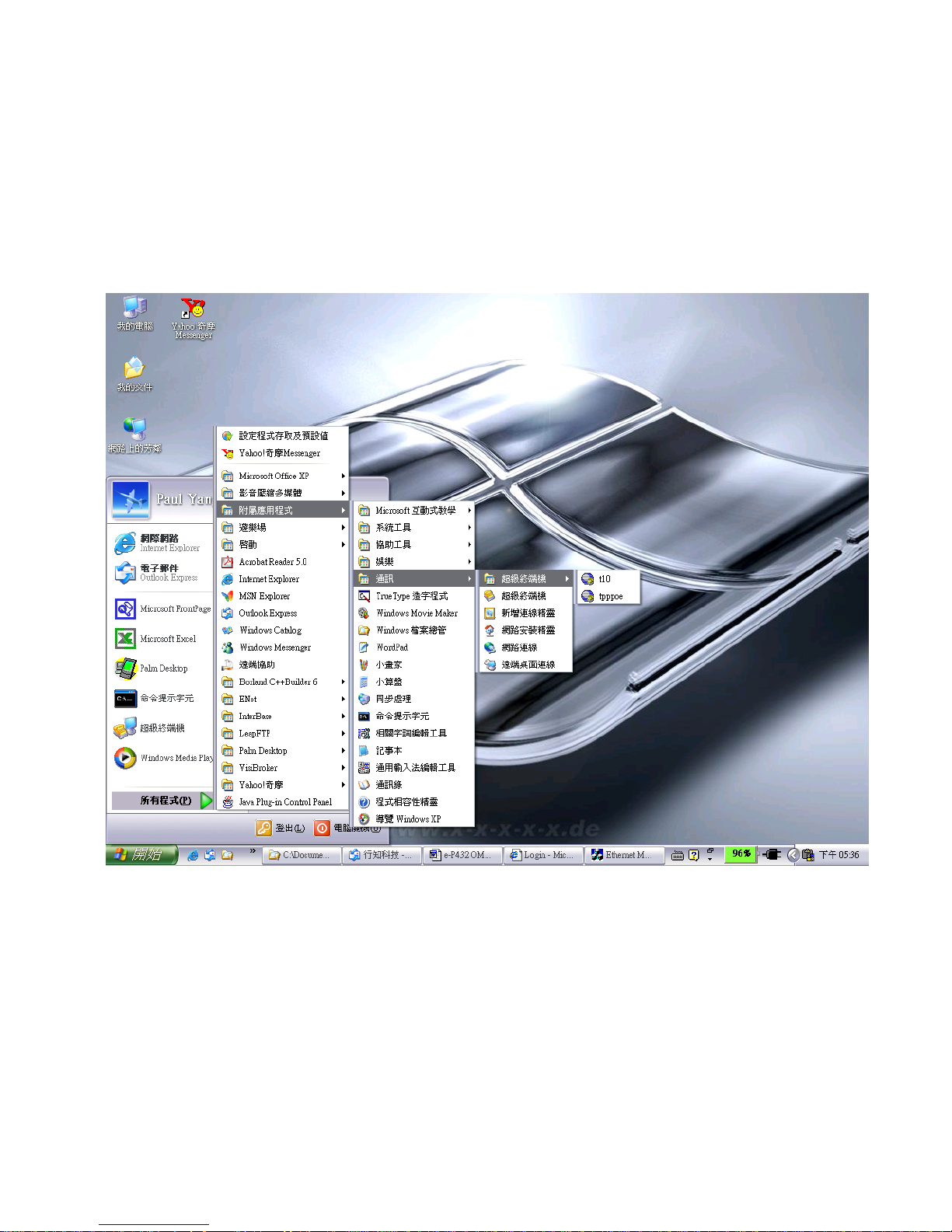
Hyper Terminal for TCP/IP WinSock
Initiate a Hyper Terminal from the Start Menu in Windows (see Figure 6.1), give a
terminal name, choose an icon, and press “OK” button (see Figure 6.2).
(Figure 6.1)

(Figure 6.2)
Select “TCP/IP(Winsock)” option at the “Connect using:” field (see Figure 6.3).
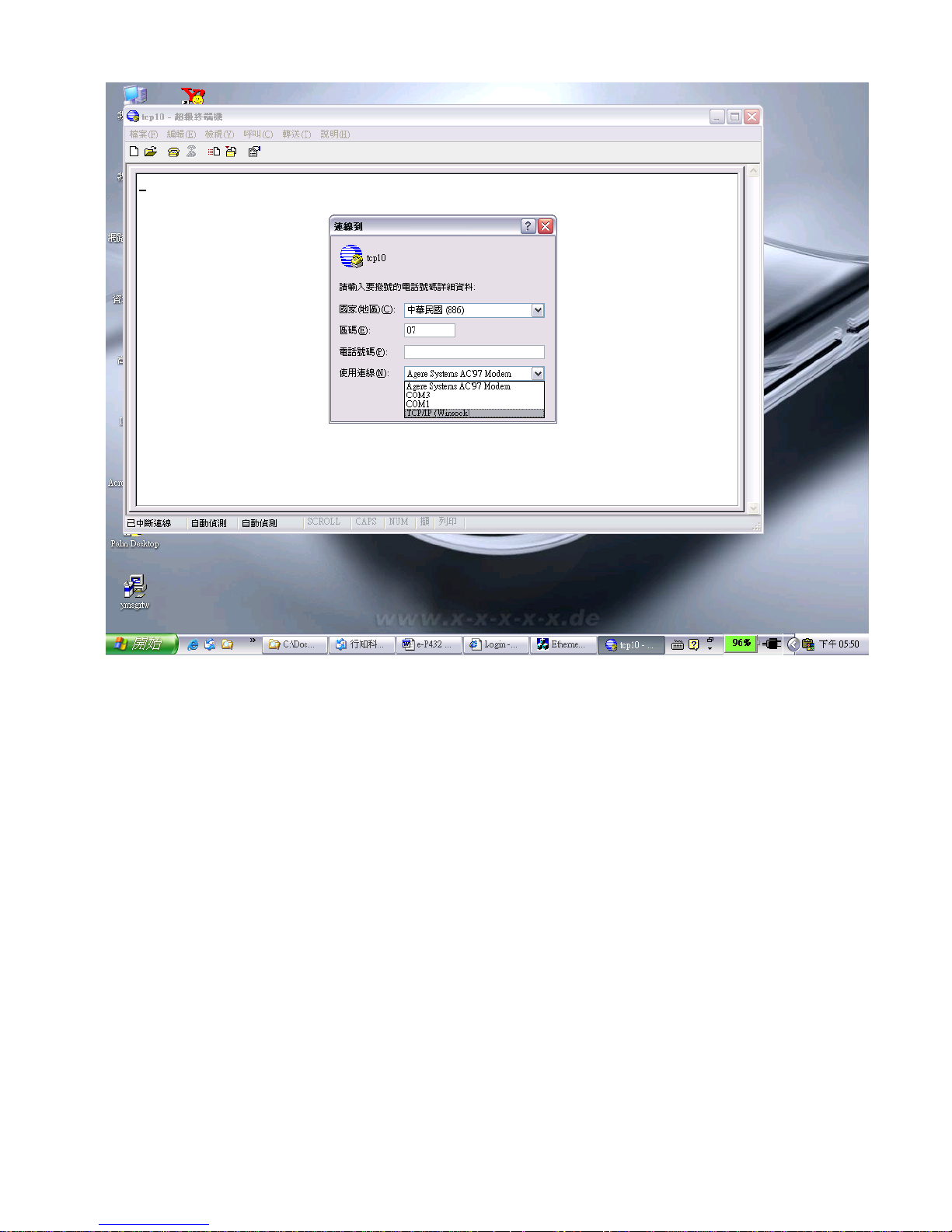
(Figure 6.3)
After “OK” button is pressed, Figure 6.4 appears. Enter the converter’s IP address (e.g.
192.168.123.10) at the “Host address:” field, and the Socket port number set for the
Serial Port 1 at the “Port number:” field (e.g 4660). (The Socket type of the Serial Port
1 should be “TCP Server”.)

(Figure 6.4)
After “OK” button is pressed, Figure 6.5 appears. If the Hyper Terminal connects with
the converter successfully, the time clock at the left lower corner “Connected hh:mm:ss”
will start counting.

(Figure 6.5)

Hyper Terminal for COM Port
Initiate another Hyper Terminal as a COM Port Terminal (in Figure 6.3, select COM 1 or
other COM port instead of “TCP/IP (Winsock)”). Set the COM port Properties to be
the same as those set for the Serial Port 1 of the converter.
(Figure 6.3)

Data Transmission
When all steps described above are finished, type any characters on the COM Port
Terminal and check if the typed characters are also displayed on the TCP/IP Winsock
Terminal. Alternatively, check if the characters typed on the TCP/IP Winsock
Terminal are also displayed on the COM Port Terminal. If yes, then all settings are
correct and the converter can operate properly.

A
Appppeennddiixx
A
A
FAQ
Q. Why can’t the CVBROWSER.exe detect the converter on the network?
A. Please check
□
□
□
if the power is properly plugged to the converter.
□
□
□
if the network cable is properly connected between the converter and the Hub.
Refer to the “Hardware Installation” steps in Chapter 3.
Q. Why can’t I use IE to setup the converter?
A. Please check if the network domain of your PC is the same as that of the converter.

A
Appppeennddiixx
B
B
Pin outs and Cable Wiring
□
□
□
DC-In Jack
□
□
□
RJ-45 Pin Assignment
Lantech
CONVERTER
RJ-45
10/100M
RS-232
- +
DC 9V
Pin No. Name
1 DCD
2 RXD
3 TXD
4 DTR
5 GND
6 DSR
7 RTS
8 CTS
9 RI
Pin No. Name
1 R2 R+
3 T4 T+
LSC-1102 Series Interface
Nameplate View
RS-422/485
RS-422/485
RS-232
Pin No. Name
1 TX+
2 TX3 RX+
6 RX-
RJ-45
,
SYSLAN
TX RX
RJ-45 Connector
Picture
□
□
□
RS-232 Pin Assignment
The pin assignment scheme for a 9-pin male connector on a DTE is given
below.
PIN 1 : N/A PIN 2 : RXD PIN 3 : TXD PIN 4 : N/A
PIN 5 : GND PIN 6 : N/A PIN 7 : RTS PIN 8 : CTS
PIN 9 : N/A

□
□
□
RS-232 Wiring Diagram
Serial Device Lantech Converter
2 RX 3 TX
3 TX 2 RX
5 GND 5 GND
7 RTS 8 CTS
8 CTS 7 RTS
□
□
□
RS-422 Pin Assignment
The pin assignment scheme for a 4-pin RS-422 is given below.
PIN 1 : R- PIN 2 : R+ PIN 3 : T- PIN 4 : T+
□
□
□
RS-422 Wiring Diagram
Serial Device Lantech Converter
R- 3 T-
R+ 4 T+
T- 1 R T+ 2 R+
□
□
□
RS-485 Wiring Diagram
Serial Device Lantech Converter
R- T- 1 R- 3 T R+ T+ 2 R+ 4 T+
1 2 3 4

A
Appppeennddiixx
D
D
Firmware Upgrade
As the firmware of the converter always keeps on enhancing with latest
technologies and network standards, if your applications need the latest
release of firmware, you will receive a Win32 executable utility and a ROM
binary file to upgrade the converter firmware through network:
1. Set the target converter to have IP address in the same subnet as your
host computer.
2. In the DOS Prompt environment of Windows, execute the upgrade
utility eUpg32.exe, with the ROM file name you received as the first
parameter and the target converter IP address as the optional second
parameter. For example:
eUpg32 ROM. bin 10.0.0.123
If you omit the target IP address, the upgrade software will try to find
one automatically.
3. The upgrade will start immediately with percent finished displayed on
screen. Wait until 100% complete. Please note during upgrade, do not
stop the software or remove the power of the converter, or it will cause
permanent damage of firmware and can not be recovered.
 Loading...