

Lantech
LGS-2816C-RPS
16 100/1000M SFP+ 8 10/100/1000T/Dual
Speed SFP Combo L2 Plus Managed
Switch w/ Redundant Power Supply
User Manual

M
ANAGEMENT
LGS-2816C-RPS
16 100/1000M SFP+ 8 10/100/1000T/Dual Speed SFP Combo L2 Plus Managed Switch w/
Redundant Power Supply
G
UIDE
LGS-2816C-RPS
Publication date: March., 2011
Revision v5.17
ABOUT THIS GUIDE
PURPOSE This guide gives specific information on how to operate and
AUDIENCE The guide is intended for use by network administrators who
CONVENTIONS The following conventions are used throughout this guide
RELATED PUBLICATIONS The following publication details the hardware features of the
use the management functions of the switch.
are responsible for operating and maintaining network
equipment; consequently, it assumes a basic working
knowledge of general switch functions, the Internet Protocol
(IP), and Simple Network Management Protocol (SNMP).
to show information:
NOTE: Emphasizes important information or calls your attention to
related features or instructions.
C
AUTION
data, or damage the system or equipment.
W
ARNING
injury.
switch, including the physical and performance-related
characteristics, and how to install the switch:
The Installation Guide
Also, as part of the switch‘s software, there is an online webbased help that describes all management related features.
:
Alerts you to a potential hazard that could cause loss of
:
Alerts you to a potential hazard that could cause personal

Release
Date
Revision
5.17
01/10/2010
B1
Revision History

CONTENTS

– 6 –
SECTION I GETTING STARTED
This section provides an overview of the switch, and introduces some basic
concepts about network switches. It also describes the basic settings
required to access the management interface.
This section includes these chapters:
◆
―Introduction‖
◆
―Initial Switch Configuration‖

1 INTRODUCTION
This switch provides a broad range of features for Layer 2 plus switching.
It includes a management agent that allows you to configure the features
listed in this manual. The default configuration can be used for most of
the features provided by this switch. However, there are many options
that you should configure to maximize the switch‘s performance for your
particular network environment.
KEY FEATURES
Table 1: Key Features
Feature Description
Configuration
Backup and
Restore
Authentication Console, Telnet, web – user name/password, RADIUS,
Access Control Lists Supports up to 128 Access Control Entries (ACEs), using the
DHCP Client Supported
DNS Proxy service
Port Configuration Speed, duplex mode, flow control, MTU, response to
Rate Limiting Input rate limiting per port (using ACL)
Port Mirroring One or more ports mirrored to single analysis port
Port Trunking Supports up to 14 trunks using either static or dynamic trunking
Storm Control Throttling for broadcast, multicast, and unknown unicast storms
Address Table Up to 8K MAC addresses in the forwarding table, 1024 static MAC
Backup to management station or TFTP server
TACACS+ Web – HTTPS
Telnet –
SSH
SNMP v1/2c - Community strings
SNMP version 3 – MD5 or SHA password
Port – IEEE 802.1X, MAC address filtering
DHCP Snooping
IP Source Guard
shared 128 ACEs for ingress classification
excessive collisions, power saving mode
(LACP)
addresse
s
IP Version 4
IEEE 802.1D Bridge Supports dynamic data switching and addresses learning
Store-andForward
Switching
Spanning Tree Algorithm Supports Rapid Spanning Tree Protocol (RSTP), which includes
Supports IPv4 addressing, management, and QoS
Supported to ensure wire-speed switching while eliminating
bad frames
STP backward compatible mode

SYSLOG
The Syslog is a standard for logging program messages . It allows
separation of the software that generates messages from the
system that stores them and the software that reports and analyzes
them. It is supported by a wide variety of devices and receivers
across multiple platforms.
QoS
Support Quality of Service by the IEEE 802.1P standard. There are
two priority queue and packet transmission schedule. multiple
platforms.
SNMP/RMON
SNMP agent and RMON MIB. In the device, SNMP agent is a client software
which is operating over SNMP protocol used to receive the command from
SNMP manager (server site) and echo the corresponded data, i.e. MIB object.
Besides, SNMP agent will actively issue TRAP information when happened.
RMON is the abbreviation of Remote Network Monitoring and is a branch of the
SNMP MIB.
The device supports MIB-2 (RFC 1213), Bridge MIB (RFC 1493), RMON MIB
(RFC 1757)-statistics Group 1,2,3,9, Ethernet-like MIB (RFC 1643), Ethernet
MIB (RFC 1643) and so on.multiple platforms.
Table 1-2: Key Features (Continued)
Feature Description
Virtual LANs Up to 4K using IEEE 802.1Q, port-based, and private VLANs
Traffic Prioritization Queue mode and CoS configured by Ethernet type, VLAN ID,
TCP/ UDP port, DSCP, ToS bit, VLAN tag priority, or port
Qualify of Service Supports Differentiated Services (DiffServ), and DSCP
remarking
Multicast Filtering Supports IGMP snooping and Proxy
DESCRIPTION OF FIRMWARE FEATURES
The switch provides a wide range of advanced performance and
Security enhancing features. Flow control eliminates the loss of packets
due to bottlenecks caused by port saturation. Storm suppression
prevents broadcast, multicast, and unknown unicast traffic storms from
engulfing the network. Untagged (port-based) and tagged VLANs, plus
support for automatic GVRP VLAN registration provide traffic security
and efficient use of network bandwidth. QoS priority queueing ensures
the minimum delay for moving real-time multimedia data across the
network. While IGMP Snooping function provides support for real-time
network applications.
Others the switch also supports TACACS+ and RADIUS authentication
for management security requirement and SSL and SSH for encryption
for all HTTP traffic and all transmitted data for secure, remote
command-line interface (CLI) access over IP networks
Some of the management features are briefly described below.

IGMP SNOOPING
Support IGMP version 2 (RFC 2236): The function IGMP snooping is
used to establish the multicast groups to forward the multicast
packet to the member ports, and, in nature, avoid wasting the
bandwidth while IP multicast packets are running over the network.
ACCESS CONTROL
LISTS
The ACLs are divided into EtherTypes. IPv4, ARP protocol, MAC and
VLAN parameters etc. Here we will just go over the standard and
extended access lists for TCP/IP. As you create ACEs for ingress
classification, you can assign a policy for each port, the policy
number is 1-8, however, each policy can be applied to any port.
This makes it very easy to determine what type of ACL policy you
will be working with.
SECURIY
AND
AUTHENTICATION
This switch provides management access via the console port,
Telnet, or a web browser. User names and passwords can be
configured locally or can be verified via a remote authentication
server (i.e., RADIUS or TACACS+).
Port-based authentication is also supported via the IEEE 802.1X
protocol. This protocol uses Extensible Authentication Protocol over
LANs (EAPOL) to request user credentials from the 802.1X client,
and then uses the EAP between the switch and the authentication
server to verify the client‘s right to access the network via an
authentication server (i.e., RADIUS server).
Other authentication options include HTTPS for secure management
access via the web, SSH for secure management access over a
Telnet-equivalent connection, SNMP Version 3, IP address filtering
for web/SNMP/Telnet/SSH management access, and MAC address
filtering for port access.
IGMP PROXY
The implementation of IP multicast processing. The switch supports IGMP
version 1 and IGMP version 2, efficient use of network bandwidth, and fast
response time for channel changing. IGMP version 1 (IGMPv1) is described in
RFC1112 ,and IGMP version 2 (IGMPv2) is described in RFC 2236. Hosts
interact with the system through the exchange of IGMP messages. Similarly,
when you configure IGMP proxy, the system interacts with the router on its
upstream interface through the exchange of IGMP messages. However, when
acting as the proxy, the system performs the host portion of the IGMP task on
the upstream interface as follows:
When queried, sends group membership reports to the group.
When one of its hosts joins a multicast address group to which
none of its other hosts belong, sends unsolicited group
membership reports to that group.
When the last of its hosts in a particular multicast group leaves the
group, sends an unsolicited leave group membership report to the
all-routers group (244.0.0.2).
NOTE: The SSL only provide the CLI for switch management and SSH
default enable without UI for management.

REDUDANT
POWER SUPPLY
Provide a D-Sub connector on rear panel to connect to RP-2000
External/Redundant system for provide a full power cord
redundancy solution that can protect against a single power main
failure
POWER SAVING
The Power saving using the "ActiPHY Power Management" and
"PerfectReach Power Management" two techniques to detect the
client idle and cable length automatically and provides the different
power.
Q-in-Q VLAN FOR
PERFORMANCE AND
SECURITY
The VLAN feature in the switch offers the benefits of both security
and performance. VLAN is used to isolate traffic between different
users and thus provides better security. Limiting the broadcast traffic
to within the same VLAN broadcast domain also enhances
performance. Q-in-Q, the use of double VLAN tags is an efficient
method for enabling Subscriber Aggregation. This is very useful in
the MAN.
MVR
Multicast VLAN Registration (MVR) can support carrier to serve
content provider using multicast for Video streaming application in
the network. Each content provider Video streaming has a dedicated
multicast VLAN. The MVR routes packets received in a multicast
source VLAN to one or more receive VLANs. Clients are in the receive
VLANs and the multicast server is in the source VLAN.
PORT CONFIGURATION You can manually configure the speed and duplex mode, and flow
control used on specific ports, or use auto-negotiation to detect the
connection settings used by the attached device. Flow control should
also be enabled to control network traffic during periods of congestion
and prevent the loss of packets when port buffer thresholds are
exceeded. The switch supports flow control based on the IEEE 802.3 x
standards.
PORT MIRRORING The switch can unobtrusively mirror traffic from any port to a monitor
You can then attach a protocol analyzer or RMON probe to this port to
perform traffic analysis and verify connection integrity.
PORT TRUNKING Ports can be combined into an aggregate connection. Trunks can be
manually set up or dynamically configured using Link Aggregation
Control Protocol (LACP). The additional ports dramatically increase the
throughput across any connection, and provide redundancy by taking
over the load if a port in the trunk should fail.
STORM CONTROL Broadcast, multicast and unknown unicast storm suppression prevents
traffic from overwhelming the network. When enabled on a port, the
level of broadcast traffic passing through the port is restricted. If
broadcast traffic rises above a pre-defined threshold, it will be throttled
until the level falls back beneath the threshold.
port.

SPANNING TREE
ALGORITHM
The switch supports these spanning tree protocols:
Spanning Tree Protocol (STP, IEEE 802.1D) – Supported by using
the STP backward compatible mode provided by RSTP. STP
provides loop detection. When there are multiple physical paths
between segments, this protocol will choose a single path and
disable all others to ensure that only one route exists between
any two stations on the network. This prevents the creation of
network loops. However, if the chosen path should fail for any
reason, an alternate path will be activated to maintain the
connection.
Rapid Spanning Tree Protocol (RSTP, IEEE 802.1w) – This
protocol reduces the convergence time for network topology
changes, for the older IEEE 802.1D STP standard. It is intended
as a complete replacement for STP, but can still interoperate with
switches running the older standard by automatically
reconfiguring ports to STP-compliant mode if they detect STP
protocol messages from attached devices.
VIRTUAL LANS
(VLANS)
The switch supports up to 4K VLANs. The VLAN is a collection of
network nodes that share the same collision domain regardless of
their physical location or connection point in the network. The
switch supports the IEEE 802.1Q tagged VLANs standard. Members
of VLAN groups can be dynamically learned via GVRP, or ports can
be manually assigned to a specific set of VLANs. By segmenting
your network into VLANs, you can:
Eliminate broadcast storms which severely degrade
performance in a flat network.
Provide data security by restricting all traffic to the originating
VLAN.
Use private VLANs to restrict traffic to pass only between data
ports and
the uplink ports, thereby isolating adjacent ports
within the same VLAN, and allowing you to limit the total
number of VLANs that need to be configured.
IP-MAC-PORT BINDING
The IP network layer uses a four-byte address. The Ethernet link
layer uses a six-byte MAC address. Binding these two address
types together allows the transmission of data between the layers.
The primary purpose of IP-MAC binding is to restrict the access to
a switch to a number of authorized users. Only the authorized
client can access the Switch‘s port by checking the pair of IP-MAC
Addresses and port number with the pre-configured database. If
an unauthorized user tries to access an IP-MAC binding enabled
port, the system will block the access by dropping its packet.

DHCP SNOOPING
This feature enables the DHCP Snooping to include information
about client when forwarding DHCP requests from a DHCP client to a
DHCP server via Trust Port. DHCP snooping can be configured on
LAN switches to harden the security on the LAN to only allow clients
with specific IP/MAC addresses to have access to the network. In
short, DHCP snooping ensures IP integrity on a Layer 2 switched
domain.
LINK LAYER
DISCOVERY PROTOCOL
(LLDP)
IEEE Standard──802.1AB (Link Layer Discovery Protocol),Provide
more easy debug tool and enhance the networking management
availability, Others it can provide auto-discovery device and
topology providing
QUALITY OF SERVICE Differentiated Services (DiffServ) provides policy-based management
mechanisms used for prioritizing network resources to meet the
requirements of specific traffic types. Each packet is classified upon entry
into the network based on access lists, DSCP values, or VLAN lists. Using
access lists allows you select traffic based on Layer 2, Layer 3, or Layer 4
information contained in each packet. Based on network policies,
different kinds of traffic can be marked for different kinds of forwarding.

Function
Parameter
Default
Console Port Connection
Baud Rate
115200 bps
Data bits
8
Stop bits
1
Parity
none
Local Console Timeout
0 (disabled)
System Information
Device Name
LGS-2816C-RPS
Account
Admin User
admin/admin
Guest User
guest/guest
Time
Manual/NTP
Manual
NTP Server
209.81.9.7
Time Zone
GMT+8:00
Daylight Saving
0 (hour)
IP Configuration
DHCP Setting
Disabled
IP Address
192.168.1.1
Subnet Mask
255.255.255.0
Default Gateway
192.168.1.254
DNS
Manual
DNS Server
0.0.0.0
Loop Detection
Detection Port
None
Management Policy
Management Policy
None
Syslog
Syslog
Disabled
IP Address
0.0.0.0
Port
514
Virtual Stack
State
Disable
Role
Slave
Group ID
default
Port Configuration
Speed
Auto
Flow Control
SYM
Masimum Frame
9600
Excessive Collision Mode
Discard
Description
Empty
Port Power Saving
Power Saving
Disable
VLAN Mode
VLAN Mode
Tag-based
SYSTEM DEFAULTS
The following table lists some of the basic system defaults.
Table: System Defaults

Function
Parameter
Default
Tag-based Group
VLAN ID
1
VLAN Name
Default
IGMP Aware
Disable
Private VLAN
Disable
GVRP propagation
Disable
Member Port
1-24 ports
Port-based Group
VLAN Name
Default
Member Port
1-24 ports
VLAN Ports
Tag Identifier
0x8100
VLAN Aware
Enable
Ingress Filtering
Disable
Frame Type
All
PVID
1
Role
Access
Untag VID
0
Double Tag
Disable
Port Isolation
Port Member
None
Management VLAN
VLAN ID
1
MAC Address Table
Age Time
300 secs
Disable automatic aging
Disable
MAC Table Learning
Auto
GVRP Config
GVRP State
Disabled
Join Time
20
Leave Time
60
LeaveAll Time
1000
Default Applicant Mode
Normal
Default Registrar Mode
Normal
Restricted Mode
Disabled
Masimum Frame
9600
Excessive Collision Mode
Discard
QoS Ports
Number of Classes
4
Default Class
Low
QCL
1
User Priority
0
Table: System Defaults (Continued)

Function
Parameter
Default
Queuing Mode
Strict Priority
Queue Weighted Low
1 Queue Weighted Normal
2
Queue Weighted Medium
4
Queue Weighted High
8
QoS Control List
QoS Control List
None
Rate Limiters
Ingress Enable
Disabled
Ingress Rate
500 Ingress Unit
Kbps
Egress Enable
Disabled
Egress Rate
500 Egress Unit
Kbps
Storm Control
Flooded unicast status
Disabled
Flooded unicast Rate
1 pps
Multicast status
Disabled
Multicast Rate
1 pps
Broadcast status
Disabled
Broadcast Rate
1 pps
ACL Ports
Policy ID
1
Action
Permit
Rate Limiter ID
Disabled
Port Copy
Disabled
Rate Limiters
Rate Limiter 1
512 pps
Rate Limiter 2
16K pps
Rate Limiter 3
32 pps
Rate Limiter 4- 16
1 pps
Table : System Defaults (Continued)

2
INITIAL SWITCH CONFIGURATION
This chapter includes information on connecting to the switch and
basic configuration procedures.
CONNECTING TO THE SWITCH
The switch has a embed network management agent. It offers a variety of
management options, including SNMP, RMON and a web- based interface.
A PC may also be connected directly to the switch for configuration and
monitoring via a command line interface (CLI).
NOTE: An IPv4 address for the switch could be obtained via DHCP
CONFIGURATION
OPTIONS
Server. To change this address, see ―Setting an IP Address‖ on page 34.
If the switch couldn‘t receive a IP Address from a DHCP server, it has a
default IP address 192.168.1.1, default gateway 192.168.1.254
and subnet mask 255.255.255.0.
The switch‘s HTTP web agent allows you to configure switch
parameters, monitor port connections, and display statistics using a
standard web browser such as Microsoft IE 6.0 above, Netscape
V7.1 above or FireFox V1.00. The switch‘s web management
interface can be accessed from any computer attached to the network.
The CLI program can be accessed by a direct connection to the RS-232
serial console port on the switch, or remotely by a Telnet connection
over the network.
The switch‘s management agent also supports SNMP (Simple Network
Management Protocol). This SNMP agent permits the switch to be
managed from any system in the network using network management
software such as Lantech View.
The switch‘s web interface, console interface, and SNMP agent allow you
to perform the following management functions:
Set the administrator password
Set an IP interface for a management VLAN
Configure SNMP parameters
Enable/disable any port

REQUIRED
CONNECTIONS
Set the speed/duplex mode for any port
Configure the bandwidth of any port by limiting input or output
rates or enable the Flow control of any port
Control port access through IEEE 802.1X security or static
address filtering
Filter packets using Access Control Lists (ACLs)
Configure up to 4K IEEE 802.1Q VLANs
Configure IGMP Snooping or Proxy functionality
Upgrade the system firmware or Import /Export configuration
files via HTTP (using the web interface) or TFTP (using the
command line interface)
Configure Spanning Tree/ RSTP/ MSTP parameters
Configure Class of Service (CoS) priority queuing and QoS
Configure the Port Trunk via static or LACP standard trunks
Enable port mirroring
Set storm control on any port for excessive broadcast, multicast,
or unknown unicast traffic
Display system information and statistics
Configure the LLDP Parameters
The switch provides an RS-232 serial port that enables a connection to
a PC or terminal for monitoring and configuring the switch. A nullmodem console cable is provided with the switch.
Attach a VT100-compatible terminal, or a PC running a terminal
emulation program to the switch. You can use the console cable provided
with this package, or use a null-modem cable that complies with the
wiring assignments shown in the Installation Guide.
To connect a terminal to the console port, complete the following steps:
1. Connect the console cable to the serial port on a terminal, or a PC
running terminal emulation software, and tighten the captive
retaining screws on the DB-9 connector.
2. Connect the other end of the cable to the RS-232 serial port on
the switch.
3. Make sure the terminal emulation software is set as follows:
■
Select the appropriate serial port (COM port 1 or COM port 2).
■
Set the baud rates to 115200 bps.

REMOTE
CONNECTIONS
■
Set the data format to 8 data bits, 1 stop bit, and no parity.
■
Set flow control to none.
■
Set the emulation mode to VT100.
■
When using HyperTerminal, select Terminal keys, not
Windows keys.
NOTE: Once you have set up the terminal correctly, the console login
screen will be displayed.
For a description of how to use the CLI, see ―Using the Command Line
Interface‖. For a list of all the CLI commands and detailed information on
using the CLI, refer to ―CLI Command Groups‖ on.
Prior to accessing the switch‘s onboard agent via a network connection,
you must first configure it with a valid IP address, subnet mask, and
default gateway using a console connection, or DHCP protocol.
An IPv4 address for this switch could be obtained via DHCP Server. To
manually configure this address or enable dynamic address assignment
via DHCP, see ―Setting an IP Address‖ on page 34.
If the switch does not receive a IP Address from a DHCP server, it will
default to the IP address 192.168.1.1, default gateway 192.168.1.254
and subnet mask 255.255.255.0.
NOTE: This switch supports the Telnet sessions or SSH sessions.
Telnet and SSH cannot be used concurrently.
After configuring the switch‘s IP parameters, you can access the
onboard configuration program from anywhere within the attached
network. The onboard configuration program can be accessed using
Telnet from any computer attached to the network. The switch can
also be managed by any computer using a web browser (Microsoft
IE 6.0 above, Netscape V7.1 above or FireFox V1.00.), or
from a network computer using SNMP network management
software.
The onboard program only provides access to basic configuration functions.
To access the full range of SNMP management functions, you must use
SNMP-based network management software.

SETTING AN IP
ADDRESS
You must establish IP address information for the switch to obtain
management access through the network. This can be done in either
of the following ways:
MANUAL
CONFIGURATION
You can manually assign an IP address to the switch. You may also
need to specify a default gateway that resides between this device
and management stations that exist on another network segment.
Valid IPv4 addresses consist of four decimal numbers, 0 to 255,
separated by periods. Anything outside this format will not be
accepted by the CLI program.
BASIC CONFIGURATION
SETTING PASSWORDS If this is your first time to log into the console interface, you could define
a new password for access to the web interface, record it, and put it in a
safe place. The password can consist of up to 15 alphanumeric
characters and is case sensitive. To prevent unauthorized access to the
switch, set the password as follows:
First to access the Switch via Console port and Type ― admin‖ default
username and ― admin‖ default password.
Then enter account configuration interface. Type ―modify admin,‖ where
password is your new password.
Managed Switch LGS-2816C-RPS
Login: admin
Password: *****
LGS-2816C-RPS(account)# modify admin
username/password: the length is from 5 to 15.
Current username (admin):admin
Current password:
New password:
Confirm password:
Username changed successfully.
Password changed successfully.
▼
Manual — You have to input the information, including IP address
and subnet mask. If your management station is not in the same IP
subnet as the switch, you will also need to specify the default gateway
router.
▼
Dynamic — The switch can obtain a IPv4 address from DHCP
address allocation servers on the network.

NOTE: An IPv4 address for this switch is 192.168.1.1 default .
ASSIGNING AN IPV4 A
Before you can assign an IP address to the switch, you must obtain
the following information from your network administrator:
▼
IP address for the switch
▼
Network mask for this network
▼
Default gateway for the network
To assign an IPv4 address to the switch, type
―set ip ip mask gateway‖
DDRESS
where ―ip‖ is the switch‘s IP address, ―mask‖ is the mask for the network
portion of the address, ―gateway‖ is the IP address of the default
gateway, Press <Enter>.
Managed Switch - LGS2816C-RPS
Login: admin
Password: *****
LGS-2816C-RPS# ip
LGS-2816C-RPS(ip)# set ip ?
Usage: set <ip> [mask] [gateway]
LGS-2816C-RPS(ip)#
LGS-2816C-RPS(ip)# set ip 192.168.20.15 255.255.255.0 192.168.20.250>
DYNAMIC CONFIGURATION
OBTAINING AN IPV4 A
If you enable the ―dhcp‖ option, IP will be enabled but will not function
until a DHCP reply has been received. Requests will be sent periodically
in an effort to obtain IP configuration information. DHCP values can
include the IP address, subnet mask, and default gateway.
If the DHCP option is enabled, the switch will start broadcasting service
requests as soon as it is powered on.
To automatically configure the switch by communicating with DHCP
address allocation servers on the network, type the following command,
and press <Enter>. Wait a few minutes, and then check the IP
configuration settings using the ―enable dhcp‖ command.
―enable dhcp‖
DDRESS

ENABLING SNMP
MANAGEMENT
ACCESS
Managed Switch - LGS-2816C-RPS
Login: admin
Password: *****
LGS-2816C-RPS# ip
LGS-2816C-RPS(ip)# enabl dhcp ?
Usage: enable dhcp <manual|auto>
LGS-2816C-RPS(ip)# enable dhcp manual
LGS-2816C-RPS(ip)# show
DHCP : Enable
IP Address : 192.168.20.15
Current IP Address : 0.0.0.0
Subnet mask : 255.255.255.0
Gateway : 192.168.20.250
Current Gateway : 255.255.255.255
DNS Setting : Manual
DNS Server : 0.0.0.0
LGS-2816C-RPS(ip)#
NOTE: Response time from DHCP servers vary considerably for different
network environments. If you do not get a response in a reasonable
amount of time, try entering the ―disable dhcp‖ command followed by
the ―enable dhcp‖ command. Otherwise, set the static IP address to a
null address, and then enter the ―dhcp enable‖ command or reboot the
switch.
The switch can be configured to accept management commands from
Simple Network Management Protocol (SNMP) applications such as
Lantech View. You can configure the switch to (1) respond to SNMP
requests or (2) generate SNMP traps.
When SNMP management stations send requests to the switch (either
to return information or to set a parameter), the switch provides the
requested data or sets the specified parameter. The switch can also be
configured to send information to SNMP managers (without being
requested by the managers) through trap messages, which inform the
manager that certain events have occurred.
The switch includes an SNMP agent that supports SNMP version 1, 2c, and
3 clients. To provide management access for version 1 or 2c clients, you
must specify a community string. The switch provides a default MIB
View (i.e., an SNMPv3 construct) for the default ―public‖ community
string that provides read access to the entire MIB tree, and a default
view for the ―private‖ community string that provides read/write access
to the entire MIB tree. However, you may assign new views to version 1
or 2c community strings that suit your specific security requirements.

COMMUNITY STRINGS (FOR SNMP VERSION 1 AND 2C CLIENTS)
Community strings are used to control management access to SNMP
version 1 and 2c stations, as well as to authorize SNMP stations to
receive trap messages from the switch. You therefore need to assign
community strings to specified users, and set the access level.
The default strings are:
▼
public - with read-only access. Authorized management stations
are only able to retrieve MIB objects.
▼
private - with read/write access. Authorized management stations
are able to both retrieve and modify MIB objects.
To prevent unauthorized access to the switch from SNMP version 1 or 2c
clients, it is recommended that you change the default community
strings.
To change the read-only or read/write community string, type either of
the following commands, and press <Enter>.
“ set community <Community> <user_name> <Source IP> <Source
Mask> “
LGS-2816C-RPS(snmp)# set community public publicuser 0.0.0.0
0.0.0.0
LGS-2816C-RPS(snmp)#
MIL-SM24DPA(snmp)# show community
SNMP Community Table:
Source IP Source Mask
---------- ---------------
0.0.0.0 0.0.0.0
Number of entries: 1
LGS-2816C-RPS(snmp)#
NOTE: If you do not intend to support access to SNMP version 1
and 2c clients, we recommend that you delete both of the
default community strings. If there are no community strings,
then SNMP management access from SNMP v1 and v2c clients is
disabled.
Idx Community UserName
--- -------------- ------------- ----
1 public publicuser

.
EXPORT OR IMPORT
CONFIGURATION
SETTINGS
Configuration commands modify the working configuration, and are
exported to a nonvolatile storage. To export the current
configuration settings to a backup server, enter the following
command, and press <Enter>.
―export <current|user> <ip_address>”
where ―ip_address‖ is the ip address of the backup server, and
―current| user”
is the name under which the configuration settings
are exported.
TRAP RECEIVERS
You can also specify SNMP stations that are to receive traps from the switch.
To configure a trap receiver, enter the ―snmp trap‖ commands shown below,
and press <Enter>.
{For SNMPv1/v2c Trap setting}
“set trap <index> <version> <IP> <port> <community/security>”
where ―version‖ indicates the SNMP client version (1, 2c, 3), ―community- string‖
specifies access rights for a version 1/2c host, and ―host-address‖ is the IP
address for the trap receiver. For a more detailed description of these
parameters and other SNMP commands. The following example creates a trap
host for a version 1 SNMP client.
>snmp trap version 1
LGS-2816C-RPS(snmp)# set trap 1 2 192.168.1.10 162 public
LGS-2816C-RPS(snmp)#
LGS-2816C-RPS(snmp)# show trap
SNMPv3 Trap Host Configuration:
No Ver. IP Port Community/Security Security Auth. Priv.
Name Level Protocol Protocol
-- ---- ------------ ---- ------------------ --------- -------- ---------
1 v2c 192.168.1.10 162 public
2
3
4
5
6
LGS-2816C-RPS(snmp)# del trap 1
LGS-2816C-RPS(snmp)#
.
Managed Switch- LGS-2816C-PRS
Login: admin
Passward:*****
LGS-2816C-PRS# config-file
LGS-2816C-PRS(config-file)#
LGS-2816C-PRS(config-file)# export ?
Usage: export <current l user> <ip_address>
LGS-2816C-PRS(config-file)# export user 192.168.20.1

C
HAPTER
2 | Initial Switch Configuration
Managing System Files
– 42 –
To Import configuration settings from a backup server, enter the following
command, and press <Enter>.“config load tftp-server file-name‖
Login: admin
Passward:*****
LGS-2816C-PRS# config-file
LGS-2816C-PRS(config-file)#
LGS-2816C-PRS(config-file)# import ?
Usage: import <current│user> <ip_address> <file_path>
Ip_address : TFTP server ip address.
LGS-2816C-PRS(config-file)# import user 192.168.20.1 LGS-2816C-RPS.config
Managed Switch- LGS-2816C-PRS
File_path : Configuration file path.

S
ECTION
II
WEB CONFIGURATION
S
ECTION
II
This section describes the basic switch features, along with a detailed
description of how to configure each feature via a web browser.
This section includes these chapters:
◆
―Using the Web Interface‖
◆
―Configuring the Switch‖

3
USING THE WEB INTERFACE
3
This switch has an embedded HTTP web agent. Using a web browser you
can configure the switch and view statistics to monitor network activity.
The web agent can be accessed by any computer on the network using a
standard web browser (Microsoft IE 6.0 above, Netscape V7.1 above
or FireFox V1.00).
NOTE: You can also use the Command Line Interface (CLI) to manage the
switch over a serial connection to the console port or via Telnet. For more
information on using the CLI, refer to ―Using the Command Line
Interface‖ on page 178.
CONNECTING TO THE WEB INTERFACE
Prior to accessing the switch from a web browser, be sure you have
first performed the following tasks:
1. Configured the switch with a valid IP address, subnet mask, and
default gateway using an out-of-band serial connection, or DHCP
protocol. (See ―Setting an IP Address‖ on page 34.)
2. Set the system password using an out-of-band serial connection. (See
―Setting Passwords‖ on page 34.)
3. After you enter a user name and password, you will have access to
the system configuration program.
NOTE: The switch only allow one user connect from RS-232 Console UI and
three user from Telnet. Others allow maximum 4 users connect via WebUI and
maximum 1 user connect via Telnet, then Maximum 5 users allowed to login
the switch via WebUI, Telnet and RS-232 Console.
NOTE: The Admin could create the Operator account. The Operator has create,
modify and delete rights as the same as Admin, but operator only has the right
to change himself password and couldn‘t do upgrade.
The guest has no right to create, modify and delete. Only has read right.
NAVIGATING THE WEB BROWSER INTERFACE
To access the web-browser interface you must first enter a user name
and password. By default, the user name is ―admin‖ and there is no
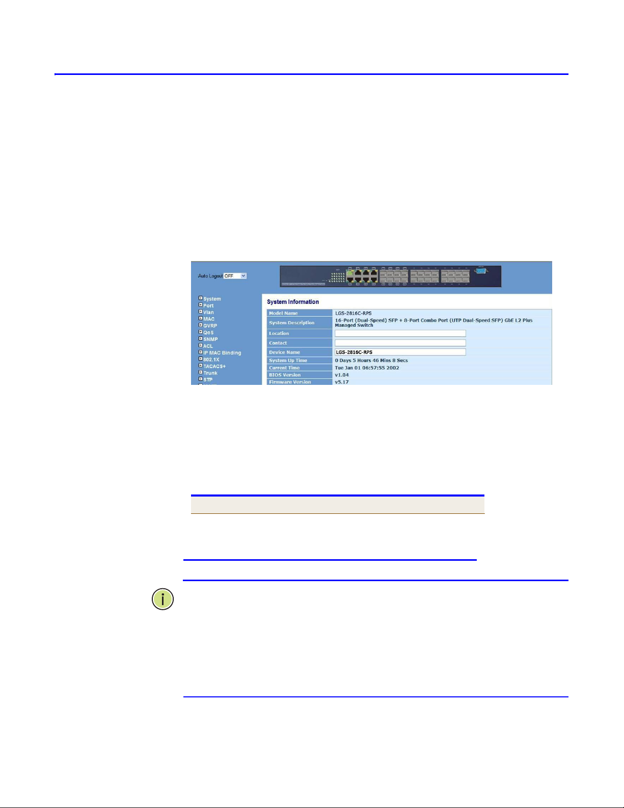
HOME PAGE When your web browser connects with the switch‘s web agent, the home
password.
page is displayed as shown below. The home page displays the Main
Menu on the left side of the screen and an image of the front panel on
the right side. The Main Menu links are used to navigate to other menus,
and display configuration parameters and statistics.
Figure 1: Home Page
CONFIGURATIO
N
OPTION
S
Configurable parameters have a dialog box or a drop-down list. Once a
configuration change has been made on a page, be sure to click on the
Apply button to confirm the new setting. The following table
summarizes the web page configuration buttons.
Table 3: Web Home Page Configuration Buttons
Button Action
Apply Sets specified values to the system.
Auto Logout Sets the device auto logout with time
period up to 60 minutes or disable the auto
logout
NOTE: To ensure proper screen refresh, be sure that Internet Explorer is
configured so that the setting ―Check for newer versions of stored
pages‖ reads ―Every visit to the page.‖
Internet Explorer 6.x and earlier: This option is available under the menu
―Tools / Internet Options / General / Temporary Internet Files / Settings.‖
Internet Explorer 7.x: This option is available under ―Tools / Internet
Options / General / Browsing History / Settings / Temporary Internet Files.‖

Menu
Description
Page
Configuration
System
System
Information
Configures Location, Contact and Device Name
Account
Configures User Account and Password
Time
Configures SNTP and System Time settings
IP Configuration
Configures IPv4 settings
Loop Detection
Configures Loop Detection
Management
Policy
Configures Management Policy
Syslog
Configures Syslog parameters
Virtual Stack
Configures the Virtual Stack for Switch Management
Port
Configuration
Configures port parameters settings
Status
Display port status
Simple Counter
Display port simple counter
Detail Counter
Display port detail counter
Power Saving
Configures port power saving settings
Vlan
Vlan mode
Configures VLAN Mode with port-base, tag-base..etc
Tag-based
Group
Configures Tag-based VLAN Group parameters setting
Port-based
Group
Configures Port-based VLAN Group parameters setting
Ports
Configures VLAN Port detail parameters setting
PANEL DISPLAY The web agent displays an image of the switch‘s ports. The refresh mode
is auto-mode by default. Clicking on the image of a port opens the
Detailed Statistics page as described on page 143.
Figure 2: Front Panel Indicators
MAIN MENU Using the onboard web agent, you can define system parameters,
manage and control the switch, and all its ports, or monitor network
conditions. The following table briefly describes the selections available
from this program.
Table 4: Main Menu

– 47 –
C
HAPTER
3 | Using the Web Interface
Navigating the Web Browser Interface
Port Isolation
Configures Port Isolation setting
Management
VLAN
Configures Management VLAN ID
MAC
MAC Address
Table
Configures MAC Address Aging parameters setting
Static Filter
Configures MAC Address Static Filter settting
Static Forward
Configures MAC Address Static Forward setting
MAC Alias
Configures MAC Address Alias setting
MAC Table
Display the MAC Address Table
GVRP
Config
Configures GVRP detail parameters setting
Counter
Display GVRP per port detail counter
Group
Configures and display the GVRP VLAN Group Information
QoS
Ports
Configures Port QoS parameters setting
QoS Control List
Configures QoS Control List setting
Rate Limiters
Configures Port Rate Limit parameters setting
Storm Control
Configures Storm Control parameters setting
Wizard
Configures QCL via Wizard setting
SNMP
System
Configures SNMP System parameters setting
Communitites
Configures SNMPv1/v2 Communities parameters setting
Users
Configures SNMP Users account and parameters setting
Groups
Configures SNMP Groups and parameters setting
Views
Configures SNMP Views and parameters setting
Accesses
Configures SNMP Accesses and parameters setting
Trap Hosts
Display the SNMP Trap Hosts information
ACL
Ports
Configures ACL Ports parameters setting
Rate Limiters
Configures ACL Rate Limit parameters setting
Access Control
List
Display and Configures ACLs Role setting

– 48 –
C
HAPTER
3 | Using the Web Interface
Navigating the Web Browser Interface
Wizard
Configures ACL via Wizard setting
IP MAC Binding
Configuration
Configures IP MAC Port Binding settings
Dynamic Entry
Configures role using dynamic entry of IP Address, MAC,
Port and VID
802.1X
Server
Configures RADIUS Authentication and Accounting Server
parameters setting
Port
Configuration
Configures Port 802.1X parameters setting
Status
Display Port 802.1X configuration information includes
Port Index, Mode, Status and VLAN Policy
Statistics
Display Port 802.1X statistics information
TACACS+
State
Configures TACACS+ State parameters setting
Authentication
Configures TACACS+ Authenticaiton parameters setting
Accounting
Configures TACACS+ Accounting parameters setting
Trunk
Port
Configures Trunk port settings and Display Trunk Port
Status
Aggregator View
Display Trunk Aggregation status and LACP Detail
information
Aggregation
Hash Mode
Configures Aggregation Mode parameters setting
LACP System
Priority
Configures LACP System Priority setting
STP (Spanning
Tree)
Status
Display the STP parameters setting information
Configuration
Configures STP parameters setting
Port
Display Port STP configuration and status information
MSTP
State
Configrues MSTP parameters setting
Region Config
Configrues MSTP Region parameters setting
Instance View
Display the MSTP Instance View information
Mirroring
Configures Port Mirroring parameters setting
SSH
Configures Secure Shell server
Multicast
IGMP Mode
Configures Multicast IGMP mode with Snooping or Proxy

– 49 –
C
HAPTER
3 | Using the Web Interface
Navigating the Web Browser Interface
Proxy
Configures IGMP Proxy parameters setting
Snooping
Configures IGMP Snooping parameters setting
IGMP Group
Allow
Configures IGMP Group Allow parameters setting
Group
Membership
Display IGMP Group Membership detail information
MVR
Configures MVR parameters setting
MVID
Configures Multicast MVID and display the detail
information
MVR Group
Allow
Configures Multicast MVR Group Allow parameters setting
MVR Group
Membership
Display Multicast MVR Group Membership detail information
Alarm
Events
Configures Trap Events parameters setting
Email
Configures Alarm trap send email and Email server
parameters setting
DHCP Snooping
DHCP Snooping
State
Configures DHCP Snooping enable or disable setting
DHCP Snooping
Entry
Display DHCP Snooping Entry detail information and
configures DHCP Snooping parameters setting
DHCP Snooping
Client
Display DHCP Snooping Client detail information
(LINK LAYER
DISCOVERY
PROTOCOL) LLDP
LLDP State
Configures per port the LLDP parameters setting
LLDP Entry
Configures switch to display per port which build the LLDP
available entry
LLDP Statistics
Display the detailed counting number of each port‘s LLDP
traffic
Save/Restore
Factory Defaults
Restore Default Configuration (Includes default
IP Address)
Save Start
Save the current configuration as a start
configuration file in flash memory
Save User
Save the current configuration as a user
configuration file in flash memory
Restore User
Restore User Configuration function can retrieve
the previous confirmed working configuration
stored in the flash memory to update start
configuration.

– 50 –
C
HAPTER
3 | Using the Web Interface
Navigating the Web Browser Interface
Export/ Import
Allows user can back up or reload the
configuration files of Save AS Start or Save As
User via TFTP Server
Diagnotics
Diagnostics
Provides a set of basic system diagnosis. The
basic system check includes EEPROM test, UART
test, DRAM test and Flash test
Ping
Tests specified path using IPv4 ping
Maintenance
Warm Restart
Provides a way to reset the switch, including
power up, hardware reset and software reset.
Firmware
Upgrade
Provides new firmware will be uploaded into the
switch and write into flash memory.
Logout
Allows you to logout the system to prevent other
users from the system without the permission.

4
CONFIGURING THE SWITCH
This chapter describes all of the basic configuration tasks.
CONFIGURING SYSTEM INFORMATION
You can identify the system by configuring the contact information,
name, and location of the switch.
WEB INTERFACE
To configure System Information in the web interface:
1. Click SYSTEM, System, Information.
2. Specify the contact information for the system administrator, as well
as the name and location of the switch. Also indicate the local time
zone by configuring the appropriate offset.
3. Click Apply.
Figure 4-1: System Information Configuration

– 52 –
C
HAPTER
4 | Configuring the Switch
Setting Account
C
HAPTER
4 | Configuring the Switch
Setting Account
PARAMETERS
These parameters are displayed on the System Information page:
Model name –The model name of this device
System description –As it is, this tells what this device
is. Here, it is “16-Port SFP + 8-Port Combo Port GbE
L2 Plus Managed Switch”.
Location – User-defined the specifies the system location.
(Maximum length: 255 characters)
Contact – For easily managing and maintaining device,
you may write down the contact person and phone here
for getting help soon. You can configure this parameter
through the device‘s user interface or SNMP.
Device name –The name of the switch. User-defined.
Default is LGS-2816C-RPS.

– 53 –
C
HAPTER
4 | Configuring the Switch
Setting Account
C
HAPTER
4 | Configuring the Switch
Setting Account
System up time – The time accumulated since this
switch is powered up. Its format is day, hour, minute,
second.
Current time – Show the system time of the switch. Its
format: day of week, month, day, hours : minutes :
seconds, year. For instance, Wed, Apr. 23, 12:10:10,
2004.
BIOS version – The version of the BIOS in this switch.
Firmware version – The firmware version in this switch.
Hardware-Mechanical version – The version of
Hardware and Mechanical. The figure before the hyphen is
the version of electronic hardware; the one after the
hyphen is the version of mechanical.
Serial number – The serial number is assigned by
Lantech.
Host IP address – The IP address of the switch.
Host MAC address – It is the Ethernet MAC address of
the management agent in this switch.
Device Port – Show all types and numbers of the port in
the switch.
RAM size – The size of the DRAM in this switch.
Flash size – The size of the flash memory in this switch.
CPU Loading – The loading of the CPU on this switch.
Model name – To display the Redundant Power Supply
system model name.
Hardware Mechanical Version – To display the
Redundant Power Supply system hardware mechanical
version.
Serial Number – To display the Redundant Power Supply
system serial number.
Temperature – To display the Redundant Power Supply
system temperature with ‗C and ‗F.

– 54 –
C
HAPTER
4 | Configuring the Switch
Setting Account
C
HAPTER
4 | Configuring the Switch
Setting Account
Fan – To display the Redundant Power Supply system fan
status with rotation speed.
Voltage – To display the Redundant Power Supply system
voltage value

– 55 –
C
HAPTER
4 | Configuring the Switch
Setting Account
C
HAPTER
4 | Configuring the Switch
Setting Account
CONFIGURING ACCOUNT
In this function, only administrator can create, modify or delete the username
and password. Administrator can modify other guest identities‘ password without
confirming the password but it is necessary to modify the administratorequivalent identity. Guest-equivalent identity can modify his password only.
WEB INTERFACE
To configure Account in the web interface:
1. Click SYSTEM, Account.
2. Click Create New to add new username and password.
3. Edit or Delete exist Accout name and password.
4. Click Apply.
NOTE: The switch only allow one user connect from RS-232 Console UI and
three user from Telnet. Others allow maximum 4 users connect via WebUI
and maximum 1 user connect via Telnet, then Maximum 5 users allowed to
login the switch via WebUI, Telnet and RS-232 Console.
NOTE: The Admin could create the Operator account. The Operator has
create, modify and delete rights as the same as Admin, but operator only has
the right to change himself password and couldn‘t do upgrade.
The guest has no right to create, modify and delete. Only has read right.
Figure 4-2: Account Configuration
PARAMETERS
These parameters are displayed on the Account configuration page:
Create New – To add a new account and password
Edit – To verified the exist account and password
Delete – To delete the exist accout and password

CONFIGURING TIME
The switch provides manual and automatic ways to set the system time via NTP.
Manual setting is simple and you just input ―Year‖, ―Month‖, ―Day‖, ―Hour‖,
―Minute‖ and ―Second‖ within the valid value range indicated in each item.
NTP is a well-known protocol used to synchronize the clock of the switch system
time over a network. NTP, an internet draft standard formalized in RFC 1305,
has been adopted on the system is version 3 protocol. The switch provides four
built-in NTP server IP addresses resided in the Internet and an user-defined NTP
server IP address. The time zone is Greenwich-centered which uses the
expression form of GMT+/- xx hours.
WEB INTERFACE
To configure Time in the web interface:
1. Click SYSTEM, Time.
2. Specify the Time parameter in manual or NTP parameters.
3. Click Apply.
NOTE: Time Zone is an offset time off GMT. You have to select the time zone
first and then perform time sync via NTP because the switch will combine this
time zone offset and updated NTP time to come out the local time
NOTE: Daylight saving is adopted in some countries. If set, it will adjust the
time lag or in advance in unit of hours, according to the starting date and the
ending date. For example, if you set the day light saving to be 1 hour. When
the time passes over the starting time, the system time will be increased one
hour after one minute at the time since it passed over.
Figure 4-3: Time Configuration

– 57 –
C
HAPTER
4 | Configuring the Switch
Setting Virtual Stack
PARAMETERS
These parameters are displayed on the Time configuration page:
Current Time – To display the current time of the system
Manual – To fill the valid figures in the fields of Year,
Month, Day, Hour, Minute and Second respectively. The
parameter Year, Month, Day, Hour, Minute and Second are
>=2000, 1-12, 1-31, 0-23, 0-59 and 0-59 respectively.
NTP – To set the switch synchronizes the time with NTP
server automatically. NTP is Network Time Protocol and is
used to sync the network time based Greenwich Mean
Time (GMT). If use the NTP mode and select a built-in NTP
time server or manually specify an user-defined NTP
server as well as Time Zone.
Daylight Saving – To set the daylight saving parameter
with unit of hours.
Daylight Saving Start – To set when to start performing
the day light saving time.
This is used to set when to start performing the day light saving time.
Mth:
Range is 1 ~ 12.
Default: 1
Day:
Range is 1 ~ 31.
Default: 1
Hour:
Range is 0 ~ 23.
Default: 0
Daylight Saving End – To set when to stop performing
the day light saving time.
This is used to set when to stop performing the daylight saving time.
Mth:
Range is 1 ~ 12.
Default: 1
Day:
Range is 1 ~ 31.

– 58 –
C
HAPTER
4 | Configuring the Switch
Setting Virtual Stack
Default: 1
Hour:
Range is 0 ~ 23.
Default: 0
Apply – To save the configuration to switch flash memory.

SETTING AN IP ADDRESS
This section describes how to configure an IP interface for management
access to the switch over the network. This switch supports IP Version
4, and can be managed simultaneously through either of the address
types. You can manually configure a specific IPv4 address or direct the
switch to obtain an IPv4 address from a DHCP server when it is
powered on.
SETTING AN
IPV4
ADDRES
S
The IPv4 address for the switch could be obtained via DHCP Server for
VLAN 1. To manually configure an address, you need to change the
switch's default settings to values that are compatible with your network.
You may also need to a establish a default gateway between the switch
and management stations that exist on another network segment.
WEB INTERFACE
To configure an IP address and SNTP in the web interface:
1. Click System, IP Configuration.
2. Specify the IPv4 settings, and enable DNS proxy service if required.
3. Click Apply.
Figure 4-4: IP & Time Configuration
NOTE: An IPv4 address for this switch could be obtained via DHCP
Server. If the switch does not receive a IP Address from a DHCP server,
it will default to the IP address 192.168.1.1 and subnet mask
255.255.255.0
You can manually configure a specific IP address, or direct the device to
obtain an address from a DHCP server. Valid IPv4 addresses consist of
four decimal numbers, 0 to 255, separated by periods. Anything other
than this format will not be accepted by the CLI program.

PARAMETERS
These parameters are displayed on the Time configuration page:
DHCP Setting – To set enable or disable the switch obtained
a IP address from DHCP Server. Default is disable
IP address – Address of the switch, Valid IP addresses
consist of four numbers, 0 to 255, separated by periods.
(Default: 192.168.1.1).
Subnet mask – This subnet mask identifies the host address
bits used for routing to specific subnet.
(Default: 255.255.255.0).
Default gateway – IP address of the gateway router between
the switch and management stations that exist on other
network segments.
(Default: 192.168.1.254).
DNS – A Domain Name Server to which client requests for
mapping host names to IP addresses are forwarded.
(Default: 0.0.0.0).
Apply – To save the configuration to switch flash memory.

CONFIGURING LOOP DETECTION
The loop detection is used to detect the presence of traffic. When switch receives
packet‘s(looping detection frame) MAC address the same as oneself from port,
show Loop detection happens. The port will be locked when it received the
looping detection frames. If you want to resume the locked port, please find out
the looping path and take off the looping path, then select the resume the locked
port and click on ―Resume‖ to turn on the locked ports.
WEB INTERFACE
To configure Loop detection in the web interface:
1. Click SYSTEM, Loop Detection.
2. Evoke which port to enable the Loop detection.
3. Click Apply.
4. When the port occur Loop and it was locked by switch then you
could resume it.
Figure 4-5: Loop Detection Configuration
PARAMETERS
These parameters are displayed on the Loop Detection configuration page:
Port No. – Display the port number. The number is 1 – 24.
Detection Port - When Port No is chosen, and enable port' s Loop
detection, the port can detect loop happens. To evoke the port to
enable auto-detect the Loop.
Locked Port – When Port No is chosen, enable port' s Loop
detection, and the port detects loop happen, the port will be
Locked. When choosing Resume, port locked will be opened and
turned into unlocked. To evoke the port to resume it.

CONFIGURING MANAGEMENT POLICY
Through the management security configuration, the manager can do the strict
NOTE: The following rules are offered for the manager to manage the switch:
Rule 1) : When no lists exists, then it will accept all connections.
Accept
-----------------------------------------------------------------------
Rule 2) : When only “accept lists” exist, then it will deny all connections, excluding
the connection inside of the accepting range.
setup to control the switch and limit the user to access this switch.
WEB INTERFACE
To configure Management Policy in the web interface:
1. Click SYSTEM, Management Policy.
2. Add a Management policy rule.
3. Click Add.
4. If you click delete then switch will delete a exist management
policy.
Rule 3) : When only “deny lists” exist, then it will accept all connections, excluding
the connection inside of the denying range.
Rule 4) : When both “accept and deny” lists exist, then it will deny all connections,
excluding the connection inside of the accepting range.
Rule 5) : When both “accept and deny” lists exist, then it will deny all connections,
excluding the connection inside of the accepting range and NOT inside of the
denying range at the same time.

Figure 4-6: Management Policy Configuration
PARAMETERS
These parameters are displayed on the Management Policy configuration page:
Add. – To create a new management policy. Specify new entry of
Management Security Configuration can be created after the
parameters as mentioned above had been setup
Delete – To delete a exist Management policy from the
management policy List.
Name - A name is composed of any letter (A-Z, a-z) and digit (0-9)
with maximal 8 characters.
VID - The switch supports two kinds of options for managed valid
VLAN VID, including ―Any‖ and ―Custom‖. Default is ―Any‖. When
you choose ―Custom‖, you can fill in VID number. The valid VID
range is 1~4094.

IP Range - The switch supports two kinds of options for managed
valid IP Range, including ―Any‖ and ―Custom‖. Default is ―Any‖. In
case that‖ Custom‖ had been chosen, you can assigned effective IP
range. The valid range is 0.0.0.0~255.255.255.255.
Incoming Port - The switch supports two kinds of options for
managed valid Port Range, including ―Any‖ and ―Custom‖. Default is
―Any‖. You can select the ports that you would like them to be
worked and restricted in the management security configuration
if ‖Custom‖ had been chosen.
Access Type - The switch supports two kinds of options for
managed valid Access Type, including ―Any‖ and ―Custom‖. Default
is ―Any‖. ―Http‖, ―Telnet‖ and ―SNMP‖ are three ways for the access
and managing the switch in case that‖ Custom‖ had been chosen.
Action – The switch supports two kinds of options for managed
valid Action Type, including ―Deny‖ and ―Accept‖. Default is ―Deny‖.
When you choose ―Deny‖ action, you will be restricted and refused
to manage the switch due to the ―Access Type‖ you choose.
However, while you select ―Accept‖ action, you will have the
authority to manage the switch.

CONFIGURING SYSLOG
The Syslog is a standard for logging program messages . It allows separation of
the software that generates messages from the system that stores them and the
software that reports and analyzes them. It can be used as well a generalized
informational, analysis and debugging messages. It is supported by a wide
variety of devices and receivers across multiple platforms.
WEB INTERFACE
To configure Syslog in the web interface:
1. Click SYSTEM, Syslog.
2. Specify the syslog parameters includes IP Address of Syslog server
3. Evoke the Sylog to enable it.
4. Click Apply.
and Port number.
Figure 4-7: Syslog Configuration
PARAMETERS
These parameters are displayed on the Syslog configuration page:
Syslog –Evoke the ―Enable‖ to enable syslog function
IP Address – To specify the IP address of the Syslog Server.
Port - Filters the log to send syslog message with the selected port
of PC host (Syslog server , ex: 514)..

CONFIGURING SYSTEM LOG
The System Log provides information about system logs, including information
when the device was booted, how the ports are operating, when users logged in,
when sessions timed out, as well as other system information.
WEB INTERFACE
To configure System Log in the web interface:
1. Click SYSTEM, System Log.
2. Display the system log on the screen.
3. Click Clear. It will clear all record of switch system log.
Figure 4-8: System Log screen
PARAMETERS
These parameters are displayed on the System Log page:
No. – Display the order number that the trap happened.
Time - Display the time that the trap happened.
Desc - Displays a description event recorded in the System Log.
Clear – To clear the system log data.

CONFIGURING VIRTUAL STACK
Virtual Stack Management(VSM) is the group management function. Through
the proper configuration of this function, switches in the same LAN will be
grouped automatically. And among these switch, one switch will be a master
machine, and the others in this group will become the slave devices. information.
VSM offers a simple centralized management function. It is not necessary to
remember the address of all devices, manager is capable of managing the
network with knowing the address of the Master machine. Instead of SNMP or
Telnet UI, VSM is only available in Web UI. While one switch become the Master,
two rows of buttons for group device will appear on the top of its Web UI. By
pressing these buttons, user will be allowed to connect the Web UI of the devices
of the group in the same window without the login of these device.
The most top-left button is only for Master device. The background color of the
button you press will be changed to represent that the device is under your
management.
NOTE: It will remove the grouping temporarily in case that you login the
switch via the console.
NOTE: Up to 16 devices can be grouped for VSM, however, only one Master is
allowed to exist in each group. For Master redundancy, user may configure
more than two devices as Master device, however, the Master device with the
smaller MAC value will be the Master one. All of these 16 devices can become
Master device and back up with each other .
WEB INTERFACE
To configure Virtual Stack in the web interface:
1. Click SYSTEM, Virtual Stack.
2. Display the system log on the screen.
3. Click Clear. It will clear all record of switch system log.
Figure 4-9: Virtual Stack Configuration

PARAMETERS
These parameters are displayed on the Virtual Stack page:
State – It is used for the activation or de-activation of VSM. Default
is Enable.
Role - The role that the switch would like to play in virtual stack.
Two types of roles, including master and slave are offered for
option. Default is Master.
Group ID - It is the group identifier (GID) which signs for VSM.
Valid letters are A-Z, a-z, 0-9, ― - ― and ―_‖ characters. The
maximal length is 15 characters.

CONFIGURING PORT CONFIGURATION
The Port Configuration page includes configuration options for enabling
auto-negotiation or manually setting the speed and duplex mode,
enabling flow control, setting the maximum frame size, specifying the
response to excessive collisions, or enabling power saving mode. Port
Configuration is applied to change the setting of each port. In this
configuration function, you can set/reset the following functions. Four
functions, including Port Status, Port Configuration, Simple Counter and
Detail Counter are contained in this function folder for port monitor and
management
WEB INTERFACE
To configure Port Configuration in the web interface:
1. Click Port, Configuration.
2. Specify the Port Configuration parameters. Make any required
changes to the connection settings
3. Click Apply.
Figure 4-10: Port Configuration
PARAMETERS
These parameters are displayed on the Port Configuration page:
Port – It was displayed the port index.
Media – It shows the port media type with UTP or SFP.
Speed - Sets the port speed and duplex mode using auto-negotiation
or manual selection. The following options are supported:
■
Disable - Disables the interface. You can disable an interface due to
abnormal behavior (e.g., excessive collisions), and then re-enable it after
the problem has been resolved. You may also disable an interface for
security reasons.

– 70 –
C
HAPTER
4 | Configuring the Switch
Configuring Power Saving
■
Auto - Enables auto-negotiation. When using auto-negotiation, the
optimal settings will be negotiated between the link partners based on
their advertised capabilities.
■
1G FDX - Supports 1 Gbps full-duplex operation
■
100Mbps FDX - Supports 100 Mbps full-duplex operation
■
100Mbps HDX - Supports 100 Mbps half-duplex operation
■
10Mbps FDX - Supports 10 Mbps full-duplex operation
■
10Mbps HDX - Supports 10 Mbps half-duplex operation
(Default: Autonegotiation enabled; Advertised capabilities for RJ-45:
1000BASE-T - 10half, 10full, 100half, 100full, 1000full; SFP: Auto
/1G FDX)
NOTE: The 1000BASE-T standard does not support forced mode.
Auto- negotiation should always be used to establish a connection
over any
1000BASE-T port or trunk. If not used, the success of the link
process cannot be guaranteed when connecting to other types of
switches.
Flow Control – Flow control can eliminate frame loss by ―blocking‖
traffic from end stations or segments connected directly to the switch
when its buffers fill. When enabled, back pressure is used for halfduplex operation and IEEE 802.3-2005 (formally IEEE 802.3x) for
full- duplex operation. (Default: Disabled)
When auto-negotiation is used, this parameter indicates the flow
control capability advertised to the link partner. When the speed and
duplex mode are manually set, the Current Rx field indicates whether
pause frames are obeyed by this port, and the Current Tx field
indicates if pause frames are transmitted from this port.
Maximum Frame - Sets the maximum transfer unit for traffic
crossing the switch. Packets exceeding the maximum frame size are
dropped. (Default: 9600 bytes)
Excessive Collision Mode – Sets the response to take when
excessive transmit collisions are detected on a port. (The function
only available on UTP Ports)
■
Discard - Discards a frame after 16 collisions (default).
■
Restart - Restarts the backoff algorithm after 16 collisions.
Description – To set the description or explain of switch specific
port, but without specific character includes “ # % & „ + \.

CONFIGURING PORT STATUS
The function Port Status gathers the information of all ports‘ current
status and reports it by the order of port number, media, link status,
port state, Auto-Negotiation status, speed/duplex, Rx Pause and Tx
Pause. An extra media type information for the module ports1 to 8 is
also offered.
WEB INTERFACE
To configure Port Configuration in the web interface:
1. Click Port, Status.
2. Display the Port status.
Figure 4-11: Port Status
PARAMETERS
These parameters are displayed on the Port Status page:
Port – Display the port number. The number is 1 – 24. Both port 1 ~
8 are optional modules.
Link - Show that if the link on the port is active or not. If the link is
connected to a working-well device, the Link will show the link ―Up‖;
otherwise, it will show ―Down‖. This is determined by the hardware
on both devices of the connection. No default value.
Speed/ Duplex Mode – It shows the speed and duplex mode of all
port. The local port has to be preset its capability. Default: None,
depnds on the result of the negotiation.
Flow Control – It shows each port‘s flow control status. There are
two types of flow control in Ethernet, Backpressure for half-duplex
operation and Pause flow control (IEEE802.3x) for full-duplex
operation. The switch supports both of them. Default: None, depends
on the result of the negotiation.

– 72 –
C
HAPTER
4 | Configuring the Switch
Configuring Power Saving
Description - network managers provide a description of device
ports.

WEB INTERFACE
To display the Port Port 1 ~ Port 24 SFP information in the web interface:
1. Right Click Port connected icon.
2. Display the Port detail information.
Figure 4-12: Port 1~ Port 24 SFP Detail Information
PARAMETERS
These parameters are displayed on the Port Detial information page:
Connector Type – Display the connector type, for instance, UTP, SC,
ST, LC and so on.
Fiber Type - Display the fiber mode, for instance, Multi-Mode,
Single-Mode.
Tx Central Wavelength - Display the fiber optical transmitting
central wavelength, for instance, 850nm, 1310nm, 1550nm and so
on.
Baud Rate - Display the maximum baud rate of the fiber module
supported, for instance, 10M, 100M, 1G and so on.
Vendor OUI - Display the Manufacturer's OUI code which is
assigned by IEEE.
Vendor Name - Display the company name of the module
manufacturer.
Vendor P/N - Display the product name of the naming by module
manufacturer.
Vendor Rev (Revision) - Display the module revision.
Vendor SN (Serial Number) - Show the serial number assigned by

– 74 –
C
HAPTER
4 | Configuring the Switch
Configuring Power Saving
the manufacturer.

Data Code - Show the date this SFP module was made.
Temperature - Show the current temperature of SFP module.
Vcc - Show the working DC voltage of SFP module.
Mon1 (Bias) mA - Show the Bias current of SFP module.
Mon2 (TX PWR) - Show the transmit power of SFP module.
Mon3 (RX PWR) - Show the receiver power of SFP module.

CONFIGURING SIMPLE COUNTER
The function of Simple Counter collects any information and provides the
counting about the traffic of the port, no matter the packet is good or
bad.
The window can show all ports‘ counter information at the same time.
Each data field has 20-digit long. If the counting is overflow, the counter
will be reset and restart counting. The data is updated every time
interval defined by the user. The Refresh Interval is used to set the
update frequency.
WEB INTERFACE
To display the Port simple counter information in the web interface:
1. Click Port, Simple Counter.
2. Display the Port Simple Counter information.
3. Click Refresh to refresh data or Clear to clear all records
4. Evoke the Auto-refresh then the switch will refresh the data automatically
Figure 4-13: Port Simple Counter detail information
PARAMETERS
These parameters are displayed on the Port Simple Counter page:
Packets -
◆ Transmit– The counting number of the packet transmitted.
◆ Receive - The counting number of the packet received.
Bytes –
◆ Transmit– Total transmitted bytes..
◆ Receive - Total received bytes.
Errors –
◆ Transmit–Number of bad packets transmitted.

◆ Receive - Number of bad packets received.
Drops –
◆ Transmit–Number of packets transmitted drop.
◆ Receive - Number of packets received drop.
◆ Auto-refresh - The simple counts will be refreshed automatically
on the UI screen.
◆ Refresh - The simple counts will be refreshed manually when
user use mouse to click on ―Refresh‖ button.
◆ Clear - The simple counts will be reset to zero when user use
mouse to click on ―Clear‖ button.

CONFIGURING DETAIL COUNTER
The function of Detail Counter collects any information and provides the
counting about the traffic of the port, no matter the packet is good or
bad.
Each data field has 20-digit long. If the counting is overflow, the counter
will be reset and restart counting. The data is updated every time
interval defined by the user. The valid range is 3 to 10 seconds. The
Refresh Interval is used to set the update frequency. Default update time
is 3 seconds.
WEB INTERFACE
To display the Port Detail Counter information in the web interface:
1. Click Port, Simple Counter.
2. Display the Port Simple Counter information.
3. Click Refresh to refresh data or Clear to clear all records
4. Evoke the Auto-refresh then the switch will refresh the data
automatically
Figure 4-14: Port Detail Counter detail information
PARAMETERS
These parameters are displayed on the Port Detail Counter page:
Rx Packets - The counting number of the packet received.
Rx Octets - Total received bytes.
Rx High Priority Packets - Number of Rx packets classified as high
priority.
Rx Low Priority Packets - Number of Rx packets classified as low
priority.

Rx Broadcast - Show the counting number of the received
broadcast packet.
Rx Multicast - Show the counting number of the received multicast
packet.
TX Packets - The counting number of the packet transmitted.
TX Octets - Total transmitted bytes.
Tx High Priority Packets - Number of Tx packets classified as high
priority.
Tx Low Priority Packets - Number of Tx packets classified as low
priority.
Tx Broadcast - Show the counting number of the transmitted
broadcast packet.
Tx Multicast - Show the counting number of the transmitted
multicast packet.
Rx 64 Bytes - Number of 64-byte frames in good and bad packets
received.
RX 65-127 Bytes - Number of 65 ~ 126-byte frames in good and
bad packets received.
Rx 128-255 Bytes - Number of 127 ~ 255-byte frames in good and
bad packets received.
Rx 256-511 Bytes - Number of 256 ~ 511-byte frames in good and
bad packets received.
Rx 512-1023 Bytes - Number of 512 ~ 1023-byte frames in good
and bad packets received.
Rx 1024-Bytes - Number of 1024-max_length-byte frames in good
and bad packets received.
Tx 64 Bytes - Number of 64-byte frames in good and bad packets
transmitted.
Tx 65-127 Bytes - Number of 65 ~ 126-byte frames in good and
bad packets transmitted.
Tx 128-255 Bytes - Number of 127 ~ 255-byte frames in good and
bad packets transmitted.
Tx 256-511 Bytes - Number of 256 ~ 511-byte frames in good and
bad packets transmitted.
Tx 512-1023 Bytes - Number of 512 ~ 1023-byte frames in good
and bad packets transmitted.
Tx 1024-Bytes - Number of 1024-max_length-byte frames in good
and bad packets transmitted.
Rx CRC/Alignment - Number of Alignment errors and CRC error
packets received.
Rx Undersize - Number of short frames (<64 Bytes) with valid CRC.
Rx Oversize - Number of long frames(according to max_length
register) with valid CRC.
Rx Fragments - Number of short frames (< 64 bytes) with invalid

– 80 –
C
HAPTER
4 | Configuring the Switch
Configuring Power Saving
CRC.
Rx Jabber - Number of long frames(according tomax_length register)
with invalid CRC.
Rx Drops - Frames dropped due to the lack of receiving buffer.
Rx Errors - Number of the error packet received.
Tx Collisions - Number of collisions transmitting frames experienced.
Tx Drops - Number of frames dropped due to excessive collision, late
collision, or frame aging.
Tx FIFO Drops - Number of frames dropped due to the lack of
transmitting buffer.
Auto-refresh - The detail counts will be refreshed automatically on
the UI screen.
Refresh - The detail counts will be refreshed manually when user use
mouse to click on ―Refresh‖ button.
Clear –The detail counts will be reset to zero when user use mouse to
click on ―Clear‖ button.

CONFIGURING POWER SAVING
The function of Power Saving and provides the Power saving for reduce
the power consumption with "ActiPHY Power Management" and
"PerfectReach Power Management" two technique.It could efficient
saving the switch Power when the client idle and detec the cable length
to provide different power.
WEB INTERFACE
To Configure the Port Power Saving in the web interface:
1. Click Port, Power Saving.
2. Evoke which port or Selec/Unselect to enable/disable Power Saving.
3. Click Apply
Figure 4-15: Port Power Saving Configuration
PARAMETERS
These parameters are displayed on the Power Saving Configuration page:
Power Saving - The parameter will enable or disable to verify
switches have the ability to consider the length of any Ethernet cable
connected for adjustment of power usage accordingly. Shorter
lengths require less power. link-down mode removes power for each
port that does not have a device attached. Default: Disable.

IEEE 802.1Q VLANS
The switch supports Tag-based VLAN (802.1Q) and Port-based VLAN.
Support 4094 active VLANs and VLAN ID 1~4094. VLAN configuration
is used to partition your LAN into small ones as your demand. Properly
configuring it, you can gain not only improving security and increasing
performance but greatly reducing VLAN management. In large
networks, routers are used to isolate broadcast traffic for each subnet
into separate domains. This switch provides a similar service at Layer
2 by using VLANs to organize any group of network nodes into
separate broadcast domains.
VLANs help to simplify network management by allowing you to move
devices to a new VLAN without having to change any physical
connections. VLANs can be easily organized to reflect departmental
groups (such as Marketing or R&D), usage groups (such as e-mail), or
multicast groups
(used for multimedia applications such as videoconferencing).
VLANs provide greater network efficiency by reducing broadcast traffic,
and allow you to make network changes without having to update IP
addresses or IP subnets. VLANs inherently provide a high level of
network security since traffic must pass through a configured Layer 3
link to reach a different VLAN.
WEB INTERFACE
To Configure the VLAN Mode in the web interface:
1. Click VLAN, VLAN Mode.
2. Scroll the VLAN mode with Tag-based, Port-based, Segment A and
3. Click Apply
Segment B.
Figure 4-16: VLAN Mode Configuration

– 83 –
C
HAPTER
4 | Configuring the Switch
Configure SNMP
Segment
Forwarding Port Mapping
1
Port 01 Port 09
2
Port 02 Port 10
3
Port 03 Port 11
4
Port 04 Port 12
5
Port 05 Port 13
6
Port 06 Port 14
7
Port 07 Port 15
8
Port 08 Port 16
9
Port 17 Port 18
10
Port 19 Port 20
11
Port 21 Port 22
12
Port 23 Port 24
PARAMETERS
These parameters are displayed on the VLAN Mode Configuration page:
Port-based - Port-based VLAN is defined by port. Any packet
coming in or outgoing from any one port of a port-based VLAN will
be accepted. No filtering criterion applies in port-based VLAN. The
only criterion is the physical port you connect to. For example, for a
port-based VLAN named PVLAN-1 contains port members Port
1&2&3&4. If you are on the port 1, you can communicate with port
2&3&4. If you are on the port 5, then you cannot talk to them. Each
port-based VLAN you built up must be assigned a group name. This
switch can support up to maximal 24 port-based VLAN groups.
Tag-based - Tag-based VLAN identifies its member by VID. This is
quite different from port-based VLAN. If there are any more rules in
ingress filtering list or egress filtering list, the packet will be
screened with more filtering criteria to determine if it can be
forwarded. The switch supports supplement of 802.1q. For more
details.
Each tag-based VLAN you built up must be assigned VLAN name
and VLAN ID. Valid VLAN ID is 1-4094. User can create total up to
4094 Tag VLAN groups.
Segment A - The ―Segment A‖ mode is a special function for LAN
Segmentation (Converter Mode) application, it is working under
VLAN function. When the segment mode enabled, there are max.
up to 12 LAN segments on the switch and fixed two ports for each
LAN segment and each LAN segment will be isolated. The fixed
segment ports mapping as below:
Segment B - The ―Segment B‖ mode is a special function for LAN
Segmentation (Converter Mode) application, it is working under
VLAN function. When the segment mode enabled, there are max.
up to 12 LAN segments on the switch and fixed two ports for each
LAN segment and each LAN segment will be isolated. The fixed
segment ports mapping as below:

Segment
Forwarding Port Mapping
1
Port 01 Port 02
2
Port 03 Port 04
3
Port 05 Port 06
4
Port 07 Port 08
5
Port 09 Port 10
6
Port 11 Port 12
7
Port 13 Port 14
8
Port 15 Port 16
9
Port 17 Port 18
10
Port 19 Port 20
11
Port 21 Port 22
12
Port 23 Port 24
The ports in the same LAN segment will forward any packet in the same
segment ports, the received packets will be forwarded to the same segment
port member without any change (for example: VLAN tag or un- tag
frames). The L2 PDU will be passed through between two ports in the same
LAN segment. (Including: STP, MSTP, GVRP, LACP,... ; Except 802.3X
Pause Frame).
NOTE: The following L2 switch functions can not work with LAN
segmentation mode at the same time:
GVRP
MSTP/RSTP/STP
IGMP Proxy and IGMP Snooping
DHCP Snooping
IP-MAC Binding
LACP and Static Port Link Aggregation
IEEE 802.1X

CONFIGURING TAG-BASED GROUP
The function shows the information of existed Tag-based VLAN Groups,
You can also easily create, edit and delete a Tag-based VLAN group by
pressing <Add>, <Edit> and <Delete> function buttons. User can
add a new VLAN group by inputting a new VLAN name and VLAN ID.
WEB INTERFACE
To Configure the Tag-based Group in the web interface:
1. Click VLAN, Tag-based Group.
2. Add new VLAN and specify the tag-based VLAN parameters.
3. Click Apply
Figure 4-17: Tag-based Group Configuration
PARAMETERS
These parameters are displayed on the Tag-Based Group Configuration page:
VLAN Name - The name defined by administrator is associated
with a VLAN group. Valid letters are A-Z, a-z, 0-9, ― - ― and ―_‖
characters. The maximal length is 15 characters.

VLAN ID - VLAN identifier. Each tag-based VLAN group has a unique VID.
It appears only in tag-based and Double-tag mode.
IGMP Proxy - IGMP proxy enables the switch to issue IGMP host
messages on behalf of hosts that the system discovered through
standard IGMP interfaces. The system acts as a proxy for its hosts.
This switch can be set IGMP function ―Enable‖ or ―Disable‖ by VLAN
group. If the VLAN group IGMP proxy is disabled, the switch will
stop the exchange of IGMP messages in the VLAN group members.
If the VLAN group IGMP proxy is enabled, the switch will support
the exchange of IGMP messages in the VLAN group members and
follow up IGMP proxy router port configuration, which connects to a
router closer to the root of the tree. This interface is the upstream
interface. The router on the upstream interface should be running
IGMP. You enable IGMP on the interfaces that connect the system
to its hosts that are farther away from the root of the tree. These
interfaces are known as downstream interfaces.
Member Port - This is used to enable or disable if a port is a
member of the new added VLAN, ―Enable‖ means it is a member of
the VLAN. Just tick the check box () beside the port x to enable it.
Add new VLAN - Please click on <Add new VLAN> to create a
new Tag-based VLAN. Input the VLAN name as well as VID,
configure the SYM-VLAN function and choose the member by ticking
the check box beside the port No., then, press the <Apply> button
to have the setting taken effect.
Delete Group - Just press the <Delete> button to delete the
selected exist group entry from the Tag-based group table.
NOTE: If you need use PVLAN( Private VLAN) function on Switch
then you need follow up the process as below:
a. Create a VLAN as primary VLAN and the VLAN ID is 2 and evoke the
Private VLAN to enable Private VLAN service.
b. Assign port member to the VLAN2
c. You need to assign these ports for member of port isolation.
d. Press the “Save” to complete the PVLAN configuration process


– 88 –
C
HAPTER
4 | Configuring the Switch
Configure SNMP
CONFIGURING PORT-BASED GROUP
The function shows the information of the existed Port-based VLAN
Groups. You can easily create, edit and delete a Port-based VLAN group
by pressing <Add>, <Edit> and <Delete> function buttons. User can
add a new VLAN group by inputting a new VLAN name.
WEB INTERFACE
To Configure the Port-based Group in the web interface:
1. Click VLAN, Port-based Group.
2. Add new VLAN and specify the Port-based VLAN parameters.
3. Click Apply
Figure 4-18: Port-based Group Configuration
PARAMETERS
These parameters are displayed on the Port-based VLAN Configuration page:
VLAN Name - The name defined by administrator is associated
with a VLAN group. Valid letters are A-Z, a-z, 0-9, ― - ― and ―_‖
characters. The maximal length is 15 characters.
Member Port - This is used to enable or disable if a port is a
member of the new added VLAN, ―Enable‖ means it is a member of
the VLAN. Just tick the check box () beside the port x to enable it.
Add new VLAN - Create a new Port-based VLAN. Input the VLAN
name and choose the member by ticking the check box beside the
port No., then, press the <Apply> button to have the setting taken
effect.
Delete Group - Just press the <Delete> button to delete the
selected exist group entry from the Port-based group table.

– 89 –
C
HAPTER
4 | Configuring the Switch
Configure SNMP
CONFIGURING PORTS
Figure 4-19 : VLAN Ports Configuration
The function in VLAN Tag Rule Setting, user can input VID number to
each port. The range of VID number is from 1 to 4094. User also can
choose ingress filtering rules to each port. There are two ingress
filtering rules which can be applied to the switch. The Ingress Filtering
Rule 1 is ―forward only packets with VID matching this port‘s configured
VID‖. The Ingress Filtering Rule 2 is ―drop untagged frame‖. You can
also select the Role of each port as Access, Trunk, or Hybrid.
WEB INTERFACE
To Configure the Ports in the web interface:
1. Click VLAN, Ports.
2. Specify the VLAN Port Configuration parameters.
3. Click Apply
PARAMETERS
These parameters are displayed on the VLAN Ports Configuration page:
Port 1-24 - The index of Port number.
VLAN Aware - Based on IEEE 802.1Q VLAN tag to forward packet.
Ingress Filtering - Discard other VLAN group packets, only
forward this port joined VLAN group packets
Frame Type –
All: Forward all tagged and untagged packets
Tagged: Forward tagged packets only and discard untagged
packets

– 90 –
C
HAPTER
4 | Configuring the Switch
Configure SNMP
PVID - This PVID range will be 1-4094. Before you set a number x
as PVID, you have to create a Tag-based VLAN with VID x. For
example, if port x receives an untagged packet, the switch will
apply the PVID (assume as VID y) of port x to tag this packet, the
packet then will be forwarded as the tagged packet with VID y.
Role - This is an egress rule of the port. Here you can choose
Access, Trunk or Hybrid. Trunk means the outgoing packets must
carry VLAN tag header. Access means the outgoing packets carry
no VLAN tag header. If packets have double VLAN tags, one will be
dropped and the other will still be left. As to Hybrid, it is similar to
Trunk, and both of them will tag-out. When the port is set to Hybrid,
its packets will be untagged out if the VID of the outgoing packets
with tag is the same as the one in the field of Untag VID of this port.
Untag VID - Valid range is 1~4094. It works only when Role is set
to Hybrid.
Double Tag - Double-tag mode belongs to the tag-based mode,
however, it would treat all frames as the untagged ones, which
means that tag with PVID will be added into all packets. Then,
these packets will be forwarded as Tag-based VLAN. So, the
incoming packets with tag will become the double-tag ones. Scroll
to enable the function and default is Disable.

CONFIGURING PORT ISOLATION
Port Isolation provides for an apparatus and method to isolate ports on
layer 2 switches on the same VLAN to restrict traffic flow. The
apparatus comprises a switch having said plurality of ports, each port
configured as a protected port or a non-protected port. An address
table memory stores an address table having a destination address and
port number pair. A forwarding map generator generates a forwarding
map which is responsive to a destination address of a data packet. The
method for isolating ports on a layer 2 switch comprises configuring
each of the ports on the layer 2 switch as a protected port or a nonprotected port. A destination address on an data packet is matched
with a physical address on said layer 2 switch and a forwarding map is
generated for the data packet based upon the destination address on
the data packet. The data packet is then sent to the plurality of ports
pursuant to the forwarding map generated based upon whether the
ingress port was configured as a protected or non-protected port.
WEB INTERFACE
To Configure the Port Isolation in the web interface:
1. Click VLAN, Port Isolation.
2. Evoke which port want to enable Port Isolation .
3. Click Save
Figure 4-20 : Port Isolation Configuration
PARAMETERS
These parameters are displayed on the Port Isolation page:
Port 1-24 - The index of Port number. To evoke the port which you
want to enable the Port Isolation service.
Save - Press the ―Save‖ to complete the PVLAN configuration
process.

– 92 –
C
HAPTER
4 | Configuring the Switch
Configure SNMP
CONFIGURING MANAGEMENT VLAN
To assign a specific VLAN for management purpose. The management
VLAN is used to establish an IP connection to the switch from a
workstation connected to a port in the VLAN. This connection supports
a VSM, SNMP, and Telnet session. By default, the active management
VLAN is VLAN 1, but you can designate any VLAN as the management
VLAN using the Management VLAN window. Only one management
VLAN can be active at a time.
When you specify a new management VLAN, your HTTP connection to
the old management VLAN is lost. For this reason, you should have a
connection between your management station and a port in the new
management VLAN or connect to the new management VLAN through a
multi-VLAN router
WEB INTERFACE
To Configure the Management VLAN in the web interface:
1. Click VLAN, Management VLAN.
2. Specify Management VLAN ID. 0~ 4094
3. Click Apply
Figure 4-21 : Management VLAN Configuration
PARAMETERS
These parameters are displayed on the Management VLAN Configuration page:
VID - Specific Management VLAN ID.

CONFIGURING MAC
Figure 4-22 : MAC Address Table Configuration
MAC Table Configuration gathers many functions, including MAC Table
Information, MAC Table Maintenance, Static Forward, Static Filter and
MAC Alias, which cannot be categorized to some function type. They
are described below.
WEB INTERFACE
To Configure the MAC Address Table in the web interface:
1. Click MAC, MAC Address Table.
2. Specify MAC Address Table parameters and evoke which port to
enable the MAC learning
3. Click Save
PARAMETERS
These parameters are displayed on the MAC Address Table Configuration page:
Aging Time - Delete a MAC address idling for a period of time from
the MAC Table, which will not affect static MAC address. Range of
MAC Address Aging Time is 10-1000000 seconds. The default Aging
Time is 300 seconds.
Disable automatic aging - Stop the MAC table aging timer, the
learned MAC address will not age out automatically.

– 94 –
C
HAPTER
4 | Configuring the Switch
Configure SNMP
Auto - Enable this port MAC address dynamic learning mechanism.
Disable - Disable this port MAC address dynamic learning
mechanism, only support static MAC address setting.
Secure - Disable this port MAC address dynamic learning
mechanism and copy the dynamic learning packets to CPU.
Save - Save MAC Address Table configuration.
Reset - Reset MAC Address Table configuration.
Flush - Remove all non-static mac entry.

CONFIGURING STATIC FILTER
Static Filter is a function that denies the packet forwarding if the
packet‘s MAC Address is listed in the filtering Static Filter table. User
can very easily maintain the table by filling in MAC Address, VID (VLAN
ID) and Alias fields individually. User also can delete the existed entry
by clicking <Delete> button.
WEB INTERFACE
To Configure the MAC Static Filter in the web interface:
1. Click MAC, Static Filter.
2. Specify Static Filter parameters includes MAC Address, VID and Alias
3. Click Apply
Figure 4-23 : MAC Static Filter Configuration
PARAMETERS
These parameters are displayed on the Static Filter Configuration page:
MAC - It is a six-byte long Ethernet hardware address and usually
expressed by hex and separated by hyphens. For example,
00 – 40 - C7 - D6 – 00 - 02
VID - VLAN identifier. This will be filled only when tagged VLAN is
applied. Valid range is 1 ~ 4094.
Alias - MAC alias name you assign.

CONFIGURING STATIC FORWARD
Static Forward is a function that allows the user in the static forward table to
access a specified port of the switch. Static Forward table associated with a
specified port of a switch is set up by manually inputting MAC address and its
alias name.
When a MAC address is assigned to a specific port, all of the switch’s traffics
sent to this MAC address will be forwarded to this port.
WEB INTERFACE
To Configure the MAC Static Forward in the web interface:
1. Click MAC, Static Forward.
2. Specify Static Forward parameters includes MAC Address, Port
No.,VID and Alias
3. Click Apply
Figure 4-24: MAC Static Forward Configuration
PARAMETERS
These parameters are displayed on the Static Filter Configuration page:
MAC - It is a six-byte long Ethernet hardware address and usually
expressed by hex and separated by hyphens. For example,
00 – 40 - C7 - D6 – 00 – 02
Port No - Port number of the switch. It is 1 ~24.
VID - VLAN identifier. This will be filled only when tagged VLAN is
applied. Valid range is 1 ~ 4094.
Alias - MAC alias name you assign.

CONFIGURING MAC ALIAS
MAC Alias function is used to let you assign MAC address a plain English name.
At the initial time, it shows all pairs of the existed alias name and MAC address.
There are three MAC alias functions in this function folder, including MAC Alias
Add, MAC Alias Edit and MAC Alias Delete. You can click <Create/Edit> button to
add/modify a new or an existed alias name for a specified MAC address, or mark
an existed entry to delete it. Alias name must be composed of A-Z, a-z and 0-9
only and has a maximal length of 15 characters.
WEB INTERFACE
To Configure the MAC Alias in the web interface:
1. Click MAC, MAC Alias.
2. Specify MAC Alias parameters includes MAC Address and Alias
3. Click Apply
Figure 4-25 : MAC Alias Configuration
PARAMETERS
These parameters are displayed on the Static Filter Configuration page:
MAC - It is a six-byte long Ethernet hardware address and usually
expressed by hex and separated by hyphens. For example,
00 – 40 - C7 - D6 – 00 – 02
Alias - MAC alias name you assign.
NOTE: If there are too many MAC addresses learned in the table, we
recommend you inputting the MAC address and alias name directly.

CONFIGURING MAC TABLE
MAC Table function is used to display the static or dynamic learning MAC entry
and the state for the selected port. There are five MAC Table information display
on the Web GUI, including MAC Alias, MAC Address, Port, VID and State.
WEB INTERFACE
To display the MAC Table in the web interface:
1. Click MAC, MAC Table.
2. Display the detail MAC Table information
3. Specify the specific MAC Address which you want to search
4. Click Search
Figure 4- 26 : MAC Table Information
PARAMETERS
These parameters are displayed on the MAC Table page:
Alias - MAC alias name you assign.
MAC address - Display the MAC address of one entry you selected
from the searched MAC entries table.
Port - The port that exists in the searched MAC Entry.
VID - VLAN identifier. This will be filled only when tagged VLAN is
applied. Valid range is 1 ~ 4094.
Status - Dynamic or Static MAC address information.
Refresh - Refresh function can help you to see current MAC Table
status.
Clear - To clear the selected entry.
Previous Page - Move to the previous page.
Next Page - Move to the next page.

CONFIGURING GVRP
GVRP is an application based on Generic Attribute Registration Protocol (GARP),
mainly used to automatically and dynamically maintain the group membership
information of the VLANs. The GVRP offers the function providing the VLAN
registration service through a GARP application. It makes use of GARP
Information Declaration (GID) to maintain the ports associated with their attribute
database and GARP Information Propagation (GIP) to communicate among
switches and end stations. With GID information and GIP, GVRP state machine
maintain the contents of Dynamic VLAN Registration Entries for each VLAN and
propagate these information to other GVRP-aware devices to setup and update
their knowledge database, the set of VLANs associated with currently active
members, and through which ports these members can be reached.
WEB INTERFACE
To display the GVRP Configuration in the web interface:
1. Click GVRP, Config.
2. Specify the GVRP Configuration Parameters
3. Click Apply
Figure 4-27 : Configure GVRP parameters
PARAMETERS
These parameters are displayed on the GVRP Configuration page:
GVRP State - This function is simply to let you enable or disable
GVRP function. You can pull down the list and click the
<Downward> arrow key to choose ―Enable‖ or ―Disable‖. Then,
click the <Apply> button, the system will take effect immediately.
Join Time - Used to declare the Join Time in unit of centisecond.
Valid time range: 20 –100 centisecond, Default: 20 centisecond.
Leave Time - Used to declare the Leave Time in unit of
centisecond. Valid time range: 60 –300 centisecond, Default: 60
centisecond.

–
C
HAPTER
4 | Configuring the Switch
Configure SNMP
Leave All Time - A time period for announcement that all
registered device is going to be de-registered. If someone still
issues a new join, then a registration will be kept in the switch.
Valid range: 1000-5000 unit time, Default: 1000 unit time.
Default Applicant Mode - The mode here means the type of
participant. There are two modes, normal participant and nonparticipant, provided for the user‘s choice.
Normal:
It is Normal Participant. In this mode, the switch participates normally
in GARP protocol exchanges. The default setting is Normal.
Non-Participant:
It is Non-Participant. In this mode, the switch does not send or reply
any GARP messages. It just listens messages and reacts for the
received GVRP BPDU.
Default Registrar Mode- The mode here means the type of
Registrar. There are three types of parameters for registrar
administrative control value, normal registrar, fixed registrar and
forbidden registrar, provided for the user‘s choice.
Normal:
It is Normal Registration. The Registrar responds normally to incoming
GARP messages. The default setting is Normal.
Fixed:
It is Registration Fixed. The Registrar ignores all GARP messages, and
all members remain in the registered (IN) state.
Forbidden:
It is Registration Forbidden. The Registrar ignores all GARP messages,
and all members remain in the unregistered (EMPTY) state.
Restricted Mode - This function is used to restrict dynamic VLAN
be created when this port received GVRP PDU. There are two modes,
disable and enable, provided for the user‘s choice.
Disabled:
In this mode, the switch dynamic VLAN will be created when this port
received GVRP PDU. The default setting is Normal.
Enabled:
In this mode, the switch does not create dynamic VLAN when this port
received GVRP PDU. Except received dynamic VLAN message of the
GVRP PDU is an existed static VLAN in the switch, this port will be
added into the static VLAN members dynamically.

CONFIGURING COUNTER
All GVRP counters are mainly divided into Received and Transmitted two
categories to let you monitor the GVRP actions. Actually, they are GARP packets.
WEB INTERFACE
To display the GVRP Counter in the web interface:
1. Click GVRP, Counter.
2. Scroll which port you want to display the GVRP Counter information.
3. Click Refresh to modify the GVRP Counter information.
Figure 4-28: Display GVRP Counter detail information
PARAMETERS
These parameters are displayed on the GVRP Counter page:
Received –
Total GVRP Packets:
Total GVRP BPDU is received by the GVRP application.
Invalid GVRP Packets:
Number of invalid GVRP BPDU is received by the GVRP
application.
LeaveAll Message Packets:
Number of GVRP BPDU with Leave All message is received by the GVRP
application.
JoinEmpty Message Packets:
Number of GVRP BPDU with Join Empty message is received by the

GVRP application.
JoinIn Message Packets:
Number of GVRP BPDU with Join In message is received by the GVRP
application.
LeaveEmpty Message Packets:
Number of GVRP BPDU with Leave Empty message is received by the
GVRP application.
Transmitted –
Total GVRP Packets:
Total GVRP BPDU is received by the GVRP application.
Invalid GVRP Packets:
Number of invalid GVRP BPDU is received by the GVRP
application.
LeaveAll Message Packets:
Number of GVRP BPDU with Leave All message is received by the GVRP
application.
JoinEmpty Message Packets:
Number of GVRP BPDU with Join Empty message is received by the
GVRP application.
JoinIn Message Packets:
Number of GVRP BPDU with Join In message is received by the GVRP
application.
LeaveEmpty Message Packets:
Number of GVRP BPDU with Leave Empty message is received by the
GVRP application.

CONFIGURING GROUP
The Function will display the dynamic group member and their detail imformation.
Others it also provide a configuration item to edit administrative Control
parameters. The detail information includes VID and Member Port.
WEB INTERFACE
To display the Group in the web interface:
1. Click GVRP, Group.
2. Display the GVRP VLAN Group Information.
3. Select a exist GVRP VLAN Group entry.
4. Click Edit Administrative Contol.
Figure 4-29: Display GVRP VLAN Group information
PARAMETERS
These parameters are displayed on the GVRP VLAN Group page:
VID - VLAN identifier. When GVRP group creates, each dynamic
VLAN group owns its VID. Valid range is 1 ~ 4094.
Member Port - Those are the members belonging to the same
dynamic VLAN group.
Edit Administrative Control - When you create GVRP group, you
can use Administrative Control function to change Applicant Mode
and Registrar Mode of GVRP group member.

CONFIGURING QoS (QUALITY OF SERVICE)
The switch support four QoS queues per port with strict or weighted fair queuing
scheduling. There are 24 QoS Control Lists (QCL) for advance programmable
QoS classification, based on IEEE 802.1p, Ethertype, VID, IPv4/IPv6 DSCP and
UDP/TCP ports and ranges.
High flexibility in the classification of incoming frames to a QoS class. The QoS
classification looks for information up to Layer 4, including IPv4 and IPv6 DSCP,
IPv4 TCP/UDP port numbers, and user priority of tagged frames. This QoS
classification mechanism is implemented in a QoS control list (QCL). The QoS
class assigned to a frame is used throughout the device for providing queuing,
scheduling, and congestion control guarantees to the frame according to what
was configured for that specific QoS class.
The switch support advanced memory control mechanisms providing excellent
performance of all QoS classes under any traffic scenario, including jumbo frame.
A super priority queue with dedicated memory and strict highest priority in the
arbitration. The ingress super priority queue allows traffic recognized as CPU
traffic to be received and queued for transmission to the CPU even when all the
QoS class queues are congested.
WEB INTERFACE
To display the QoS Configuration in the web interface:
1. Click QoS, Ports.
2. Specify the Port QoS Paramter and Scroll the setting.
3. Click Apply.
Figure 4-30: Display QoS Ports Configuration
PARAMETERS
These parameters are displayed on the QoS Ports Configuration page:
Number of Classes – Scroll the value with 1/2/4.
Port - User can choose the port (1~24) respectively with Priority
Class on Per Port Priority function.

Default Class - User can set up High Priority or Low Priority for
each port respectively. You could scroll with Low / Normal / Medium /
High
QCL - The number of QCL rule 1~24, each port have to apply one
of the QCL rule for QoS behavior. You could scroll with 1 to 24.
User priority - The user priority value 0~7 (3 bits) is used as an
index to the eight QoS class values for VLAN tagged or priority
tagged frames. You could scroll with 0 to 7.
Queuing Mode - There are two Scheduling Method, Strict Priority
and Weighted Fair. Default is Strict Priority. After you choose any of
Scheduling Method, please click Apply button to be in operation.
You could scroll with Strict Priority and Weighted Fair two mode.
Queue Weighted - There are four queues per port and four classes
weighted number (1 / 2 / 4 / 8) for each queues, you can select the
weighted number when the scheduling method be set to ―Weighted
Fair‖ mode.
NOTE: If you want to set the Queue Weighted then you must to scroll the
Queuing Mode with Weighted Fair mode first.

CONFIGURING QoS CONTROL LIST
The switch support four QoS queues per port with strict or weighted fair queuing
scheduling. There are 24 QoS Control Lists (QCL) for advance programmable
QoS classification, based on IEEE 802.1p, Ether Type, VID, IPv4/IPv6 DSCP and
UDP/TCP ports and ranges.
WEB INTERFACE
To display the QoS Control List Configuration in the web interface:
1. Click QoS, QoS Control List.
2. Scroll the QCL rule number. The value from 1 to 24
3. Press
4. Specify the QCL Parameters.
Figure 4-31: Display QoS Control List Configuration
PARAMETERS
These parameters are displayed on the QoS Control List page:
QCL# – Scroll the value with 1to 24.
QCE Type – You could scroll QCE Type with the Ethernet Type /
VLAN ID / UDP/TCP Port / DSCP / ToS / Tag Priority
Ethernet Type Value - The configurable range is 0x600~0xFFFF.
Well known protocols already assigned EtherType values. The
commonly used values in the EtherType field and corresponding
protocols are listed below:

Ethertype
(Hexadecimal)
Protocol
0x0800
IP, Internet Protocol
0x0801
X.75 Internet
0x0802
NBS Internet
0x0803
ECMA Internet
0x0804
Chaosnet
0x0805
X.25 Level 3
0x0806
ARP, Address Resolution Protocol.
0x0808
Frame Relay ARP [RFC1701]
0x6559
Raw Frame Relay [RFC1701]
0x8035
DRARP, Dynamic RARP. RARP, Reverse
Address Resolution Protocol.
0x8037
Novell Netware IPX
0x809B
EtherTalk (AppleTalk over Ethernet)
0x80D5
IBM SNA Services over Ethernet
0x 80F3
AARP, AppleTalk Address Resolution
Protocol.
0x8100
IEEE Std 802.1Q - Customer VLAN Tag Type.
0x8137
IPX, Internet Packet Exchange.
0x 814C
SNMP, Simple Network Management
Protocol.
0x86DD
IPv6, Internet Protocol version 6.
0x880B
PPP, Point-to-Point Protocol.
0x 880C
GSMP, General Switch Management
Protocol.
0x8847
MPLS, Multi-Protocol Label Switching
(unicast).
0x8848
MPLS, Multi-Protocol Label Switching
(multicast).
0x8863
PPPoE, PPP Over Ethernet (Discovery
Stage).
0x8864
PPPoE, PPP Over Ethernet (PPP Session
Stage).
0x88BB
LWAPP, Light Weight Access Point Protocol.
0x88CC
LLDP, Link Layer Discovery Protocol.

0x8E88
EAPOL, EAP over LAN.
0x9000
Loopback (Configuration Test Protocol)
0xFFFF
reserved.
VLAN ID - The configurable VID range:1~4094.
UDP/TCP Port - To select the UDP/TCP port classification method
by Range or Specific.
UDP/TCP Port Range - The configurable ports range:
0~65535You can refer to following UDP/TCP port-numbers
information.
http://www.iana.org/assignments/port-numbers
UDP/TCP Port No - The configurable specific port value: 0~65535.
DSCP Value - The configurable DSCP value: 0~63.
Traffic Class – You could scroll traffic class with Low / Normal /
Medium / High.

CONFIGURING RATE LIMITERS
Each port includes an ingress policer, and an egress shaper, which can limit the
bandwidth of received and transmitted frames. Ingress policer or egress shaper
operation is controlled per port in the Rate Limit Configuration.
WEB INTERFACE
To display the QoS Rate Limiters Configuration in the web interface:
1. Click QoS, Rate limiters.
2. To set an rate limit on ingress traffic, check Policer Enabled box next
to the required port, set the rate limit in the Policer Rate field, and
select the unit of measure for the traffic rate.
3. To set an rate limit on egress traffic, check Shaper Enabled box next
to the required port, set the rate limit in the Shaper Rate field, and
select the unit of measure for the traffic rate.
4. Scroll the Ingress and Egress Unit with kbps or Mbps
5. Click Apply
Figure 4-32: Display QoS Rate Limiters Configuration
PARAMETERS
These parameters are displayed on the QoS Rate Limiter page:
Port # – Display the Port Index.
Ingress Shaper Enabled – Evoke to enable the Ingress rate
limiter rule.
Ingress Shaper Rate (rule) - Configures the rate for the port
shaper.
(Range: 500-1000000 kbps, or 1-1000 Mbps; Default: 500 kbps)
Ingress Shaper Unit – Sets the unit of measure for the port
shaper. (Options: kbps, Mbps; Default: kbps)

Egress Shaper Enabled – Evoke to enable the Egress rate limiter
rule.
Egress Rate (rule) - - Configures the rate for the port shaper.
(Range: 500-1000000 kbps, or 1-1000 Mbps; Default: 500 kbps)
Egress Shaper Unit – Sets the unit of measure for the port shaper.
(Options: kbps, Mbps; Default: kbps)

CONFIGURING STORM CONTROL
You can configure limits on broadcast, multicast and unknown unicast traffic to
control traffic storms which may occur when a network device is malfunctioning,
the network is not properly configured, or application programs are not well
designed or properly configured. Traffic storms caused by any of these problems
can severely degrade performance or bring your network to a complete halt.
You can protect your network from traffic storms by setting a threshold for
broadcast, multicast, or unknown unicast traffic. Any packets exceeding the
specified threshold will then be dropped. Note that the limit specified on this page
applies to each port
WEB INTERFACE
To configure Storm Control:
1. Click QoS, Storm Control.
2. Enable storm control for Flooded unicast, Multicast, or
Broadcast traffic by marking the Status box next to the
required frame type.
3. Select the control rate as a function of 2
suffix for the unit of measure) or a rate in Kpps (i.e., a value
marked with the suffix ―K‖).
4. Click Apply.
n
pps (i.e., a value with no
Figure 4-33: Storm Control Configuration
PARAMETERS
These parameters are displayed on the QoS Storm Control page:
Frame Type – Specifies Broadcast, Multicast or Flooded unicast
traffic..
Status – Enables or disables storm control. (Default: Disabled)

Rate (pps) - The threshold above which packets are dropped. This
limit can be set by specifying a value of 2n packets per second (pps),
or by selecting one of the options in Kpps. 1 / 2 / 4 / 8 / 16 / 32 /
64 / 128 / 256 / 512 / 1K / 2K / 4K / 8K / 16K / 32K / 64K / 128K /
256K / 512K / 1024K
NOTE: Due to an ASIC limitation, the enforced rate limits are slightly less
than the listed options. For example: 1 Kpps translates into an enforced
threshold of 1002.1 pps. directly.

CONFIGURING QoS WIZARD
You can use the QCL configuration Wizard is targeted on user can easy to
configure the QCL rules for QoS configuration. The wizard provide the typical
network application rules, user can apply these application easily.
WEB INTERFACE
To configure QoS Wizard:
1. Click QoS, Wizard.
2. Choice one of four rules for action .
3. Click Next to next step of configuration
4. Follw up the GUI procedure to set all parameters.
Figure 4-34: Select 1 of 4 QCL Configuration Wizards
PARAMETERS
These parameters are displayed on the QCL Wizard page:
Please select an Action –User need to select one of action from
following items, then click on <Next> to finish QCL configuration:
Set up Port Policies
Set up Typical Network Application Rules
Set up TOS Precedence Mapping
Set up VLAN Tag Priority Mapping
Next –Go to next step.
Cancel - Abort current configuration back to previous step.
Back - Back to previous screen

Figure 4-35: Set up Policy Rules
PARAMETERS
These parameters are displayed on the QCL Wizard page:
QCL ID – Display the QoS Control List (QCL) Index from 1 to 24
Port Member – Evoke the port to join the QCL ID and become the
QCL Member.
Wizard Again - Click on the <Wizard Again> , back to QCL
Configuration Wizard
Finish - When you click on <Finish>, the parameters will be set
according to the wizard configuration and shown on the screen, then
ask you to click on <Apply> for changed parameters confirmation.

Figure 4-36: Set up Port Policy Finish
Figure 4-37: Set up Typical Network Application Rules
PARAMETERS
These parameters are displayed on the QCL Wizard page:
Audio and Video – QuickTime 4 Server / MSN Messenger Phone /
Yahoo Messenger Phone / Napster / Real Audio
Games - Blizzard Battlenet (Diablo2 and StarCraft) / Fighter Ace II /
Quake2 / Quake3 / MSN Game Zone
User Definition - Ethernet Type / VLAN ID / UDP/TCP Port / DSCP.
Ethernet Type Value - Type Range: 0x600~0xFFFF.
VLAN ID – To set the VLAN ID Range: 1~4094
UDP/TCP Port – Set with Two Mode: Range / Specific.
UDP/TCP Port Range – Set the Port Range: 0~65535
UDP/TCP Port No - Set the Port Range: 0~65535
DSCP Value – Set the DSCP Value Range: 0~63

Figure 4-38: Set up Typical Network Application Rules
PARAMETERS
These parameters are displayed on the QCL Wizard page:
QCL ID – Scroll to set the QCL ID from 1 to 24
Traffic Class – Scroll to set the Traffic Class with Low/ Normal/
Medium/ High
Figure 4-39: Set up TOS Precedence Mapping Rules

PARAMETERS
These parameters are displayed on the QCL Wizard page:
QCL ID – Scroll to set the QCL ID from 1 to 24
TOS Precedence 0- 7 Class – Scroll to set the TOS Precedence
Mapping Class with Low/ Normal/ Medium/ High
Figure 4-40: Set up VLAN Tag Priority Mapping Rules
PARAMETERS
These parameters are displayed on the QCL Wizard page:
QCL ID – Scroll to set the QCL ID from 1 to 24
Tag Priority 0- 7 Class – Scroll to set the Tag Priority Mapping
Class with Low/ Normal/ Medium/ High

CONFIGURING SNMP (SIMPLE NETWORK MANAGEMENT PROTOCOL)
Simple Network Management Protocol (SNMP) is a communication
protocol designed specifically for managing devices on a network.
Equipment commonly managed with SNMP. SNMP is typically used to
configure these devices for proper operation in a network environment,
as well as to monitor them to evaluate performance or detect potential
problems.
Managed devices supporting SNMP contain software, which runs locally
on the device and is referred to as an agent. A defined set of variables,
known as managed objects, is maintained by the SNMP agent and used
to manage the device. These objects are defined in a Management
Information Base (MIB) that provides a standard presentation of the
information controlled by the agent. SNMP defines both the format of
the MIB specifications and the protocol used to access this information
over the network.
The switch includes an onboard agent that supports SNMP versions 1,
2c, and 3. This agent continuously monitors the status of the switch
hardware, as well as the traffic passing through its ports. A network
management station can access this information using software such as
LantechView. Access to the onboard agent from clients using SNMP v1
and v2c is controlled by community strings. To communicate with the
switch, the management station must first submit a valid community
string for authentication.
Access to the switch using from clients using SNMPv3 provides
additional security features that cover message integrity,
authentication, and encryption; as well as controlling user access to
specific areas of the MIB tree. The SNMPv3 security structure consists
of security models, with each model having it's own security levels.
There are three security models defined, SNMPv1, SNMPv2c, and
SNMPv3. Users are assigned to ―groups‖ that are defined by a security
model and specified security levels.
Basically, it is passive except issuing the trap information. The switch
supports a switch to turn on or off the SNMP agent. If you set the field
SNMP ―Enable‖, SNMP agent will be started up. All supported MIB OIDs,
including RMON MIB, can be accessed via SNMP manager. If the field
SNMP is set ―Disable‖, SNMP agent will be de-activated, the related
Community Name, Trap Host IP Address, Trap and all MIB counters will
be ignored.
NOTE: The predefined default groups and view can be deleted from
the system. You can then define customized groups and views for the
SNMP clients that require access.
 Loading...