

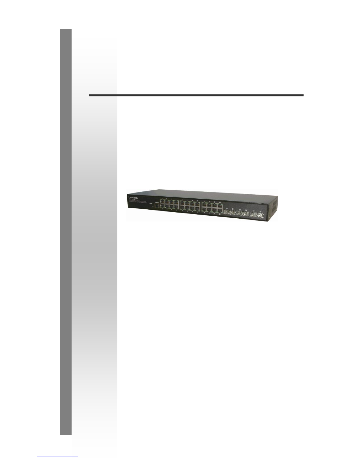
LGS-2624C
20 10/100/1000T + 4 100/1000M
SFP Combo + 2 100/1000M SFP L2
Plus Managed Switch
User Manual
v1.00
Sept 2011

The information in this document is subject to change without notice. Unless the explicit written permission of Manufacture Corporation, this
document in whole or in part shall not be replicated or modified or amended or transmitted, in any from, or by any means manual, electric,
electronic, electromagnetic, mechanical, optical or otherwise for any purpose.
DURATION OF HARDWARE WARRANTY
HARDWARE: In accordance with the provisions described under, Manufacture Corporation (hereinafter called ―Manufacture‖) warrants its
hardware products (hereinafter referred to as ―Product‖) specified herein to be for a period of twelve (12) months from the date of shipment.
Should a Product fail to perform during the effective warranty period as described above, Manufacture shall replace the defective Product or
part, or delivering a functionally equivalent Product or part in receipt of customer’s request, provided that the customer complies with the
return material authorization (RMA) procedures and returns all defective Product prior to installation of the replacements to Manufacture.
All defective Products must be returned to Manufacture with issuance of a Return Material Authorization number (RMA number) assigned to
the reseller from whom the end customer originally purchased the Product. The reseller is responsible for ensuring the shipments are
insured, with the transportation charges prepaid and the RMA number clearly marked on the outside of the package. Manufacture will not
accept collect shipments or those returned without an RMA number.
Manufacture shall not be responsible for any software, firmware, information or memory data contained in, stored on or integrated with any
Product returned to Manufacture pursuant to any warranty.
EXCLUSIONS. The warranty as mentioned above does not apply to the following conditions, in Manufacture’s judgment, it contains (1)
customer does not comply with the manual instructions offered by Manufacture in installation, operation, repair or maintenance, (2) Product
fails due to damage from unusual external or electrical stress, shipment, storage, accident, abuse or misuse, (3) Product is used in an extra
hazardous environment or activities, (4) any serial number on the Product has been removed or defaced, (5) this warranty will be of no
effect if the repair is via anyone other than Manufacture or the approved agents, or (6) In the event of any failures or delays by either party
hereto in the performance of all or any part of this agreement due to acts of God, war, riot, insurrection, national emergency, strike, embargo,
storm, earthquake, or other natural forces, or by the acts of anyone not a party to this agreement, or by the inability to secure materials or
transportation, then the party so affected shall be executed from any further performance for a period of time after the occurrence as may
reasonably be necessary to remedy the effects of that occurrence, but in no event more than sixty (60) days. If any of the stated events
should occur, Party A shall promptly notify Party B in writing as soon as commercially practicable, but in no event more than twenty (20)
business days and provide documentation evidencing such occurrence. In no event shall the maximum liability of Manufacture under this
warranty exceed the purchase price of the Product covered by this warranty.
DISCLAIMER. EXCEPT AS SPECIFICALLY PROVIDED ABOVE AS REQUIRED ―AS IS‖ AND THE WARRANTIES AND REMEDIES
STATED ABOVE ARE EXCLUSIVE AND IN LIEU OF ALL OTHERS, ORAL OR WRITTEN, EXPRESS OR IMPLIED. ANY AND ALL OTHER
WARRANTIES, INCLUDING IMPLIED WARRANTIES OF MERCHANTABILITY, FITNESS FOR A PARTICULAR PURPOSE AND
NONINFRINGEMENT OR THIRD PARTY RIGHTS ARE EXPRESSLY EXCLUDED.
MANUFACTURE SOFTWARE LICENSE AGREEMENT
NOTICE: Please carefully read this Software License Agreement (hereinafter referred to as this ―Agreement‖) before copying or using the
accompanying software or installing the hardware unit with pre-enabled software or firmware (each of which is referred to as ―Software‖ in
this Agreement). BY COPYING OR USING THE SOFTWARE, YOU ACCEPT ALL OF THE PROVISIONS AND CONDITIONS OF THIS
AGREEMENT. THE PROVISIONS EXPRESSED IN THIS AGREEMENT ARE THE ONLY PROVISION UNDER WHICH MANUFACTURE
WILL PERMIT YOU TO USE THE SOFTWARE. If you do not accept these provisions and conditions, please immediately return the unused
software, manual and the related product. Written approval is NOT a prerequisite to the validity or enforceability of this Agreement and no
solicitation of any such written approval by or on behalf of Manufacture shall be deemed as an inference to the contrary.
LICENSE GRANT. The end user (hereinafter referred to as ―Licensee‖) of the Software is granted a personal, non-sublicensable,
nonexclusive, nontransferable license by Manufacture Corporation (―Manufacture‖): (1) To use the Manufacture’s software (―So ftware‖) in
object code form solely on a single central processing unit owned or leased by Licensee or otherwise embedded in the equipment offered by
Manufacture. (2) To copy the Software only for backup purposes in support of authorized use of the Software. (3) To use and copy the
documentation related to the Software solely in support of authorized use of the Software by Licensee. The License applies to the Software
only except other Manufacture’s software or hardware products. Without the prior written consent of Manufacture, Lic ensee has no right to
receive any source code or design documentation with respect to the Software.
RESTRICTIONS ON USE; RESERVATION OF RIGHTS. The Software and related documentation are protected under copyright laws.
Manufacture and/or its licensors retain all title and ownership in both the Software and its related documentation, including any revisions
made by Manufacture. The copyright notice must be reproduced and included with any copy of any portion of the Software or related
documentation. Except as expressly authorized above, Licensee shall not copy or transfer the Software or related documentation, in whole
or in part. Licensee also shall not modify, translate, decompile, disassemble, use for any competitive analysis, reverse compile or reverse
assemble all or any portion of the Software, related documentation or any copy. The Software and related documentation embody
Manufacture’s confidential and proprietary intellectual property. Licensee is not allowed to disclose the Software, or any i nformation about
the operation, design, performance or implementation of the Software and related documentation that is confidential to Manufacture to any
third party. Software and related documentation may be delivered to you subject to export authorization required by governments of Taiwan
and other countries. You agree that you will not export or re-export any Software or related documentation without the proper export licenses
required by the governments of affected countries.
LIMITED SOFTWARE WARRANTY. Manufacture warrants that any media on which the Software is recorded will be free from defects in
materials under normal use for a period of twelve (12) months from date of shipment. If a defect in any such media should occur during the
effective warranty period, the media may be returned to Manufacture, then Manufacture will replace the media. Manufacture shall not be
responsible for the replacement of media if the failure of the media results from accident, abuse or misapplication of the media.
EXCLUSIONS. The warranty as mentioned above does not apply to the Software, which (1) customer does not comply with the manual
instructions offered by Manufacture in installation, operation, or maintenance, (2) Product fails due to damage from unusual external or
electrical stress, shipment, storage, accident, abuse or misuse, (3) Product is used in an extra hazardous environment or activities, (4) any
serial number on the Product has been removed or defaced, or (5) this warranty will be of no effect if the repair is via anyone other than
Manufacture or the authorized agents. The maximum liability of Manufacture under this warranty is confined to the purchase price of the
Product covered by this warranty.

DISCLAIMER. EXCEPT AS PROVIDED ABOVE, THE SOFTWARE IS PROVIDED ―AS IS ‖ AND MANUFACTURE AND ITS LICENSORS
MAKE NO WARRANTIES, EXPRESS OR IMPLIED, WITH REPSECT TO THE SOFTWARE AND DOCUMENTAITON. MANUFACTURE
AND ITS LICENSORS DISCLAIM ALL OTHER WARRANTIES, INCLUSIVE OF WITHOUT LIMITATION, IMPLIED WARRANTIES OR
MERCHANTABILITY, FITNESS FOR A PARTICULAR PURPOSE AND NONINFRINGEMENT. FURTHER, MANUFACTURE DOES NOT
WARRANT, GUARANTEE, OR MAKE ANY REPRESENTATIONS REGARDING THE USE, OR THE RESULTS OF THE USE, OF THE
SOFTWARE OR RELATED WRITTEN DOCUMENTAITON IN TERMS OF CORRECTNESS, ACCURACY, RELIABILITY, OR OTHERWISE.
CONSEQUENTIAL DAMAGES. IN NO EVENT SHALL MANUFACTURE OR ITS AUTHORIZED RESELLER BE LIABLE TO LICENSEE
OR ANY THIRD PARTY FOR (A) ANY MATTER BEYOND ITS REASONABLE CONTROL OR (B) ANY CONSEQUENTIAL, SPECIAL,
INDIRECT OR INCIDENTAL DAMAGES ARISING OUT OF THIS LICENSE OR USE OF THE SOFTWARE PROVIDED BY
MANUFACTURE, EVEN IF MANUFACTURE HAS BEEN NOTIFIED OF THE POSSIBILITY OF SUCH DAMAGES IN ADVANCE. IN NO
EVENT SHALL THE LIABILITY OF MANUFACTURE IN CONNECTION WITH THE SOFTWARE OR THIS AGREEMENT EXCEED THE
PRICE PAID TO MANUFACTURE FOR THE LICENSE.
TERM AND TERMINATION. The License is effective until terminated; however, all of the restrictions in regard to Manufacture’s copyright in
the Software and related documentation will cease being effective at the date of expiration; Notwithstanding the termination or expiration of
the term of this agreement, it is acknowledged and agreed that those obligations relating to use and disclosure of Manufacture’s confidential
information shall survive. Licensee may terminate this License at any time by destroying the software together with all copies thereof. This
License will be immediately terminated if Licensee fails to comply with any term and condition of the Agreement. Upon any termination of
this License for any reason, Licensee shall discontinue to use the Software and shall destroy or return all copies of the Software and the
related documentation.
GENERAL. This License shall be governed by and construed pursuant to the laws of Taiwan. If any portion hereof is held to be invalid or
unenforceable, the remaining provisions of this License shall remain in full force and effect. Neither the License nor this Agreement is
assignable or transferable by Licensee without Manufacture’s prior written consent; any attempt to do so shall be void. This License
constitutes the entire License between the parties with respect to the use of the Software.
LICENSEE ACKNOWLEDGES THAT LICENSEE HAS READ THIS AGREEMENT, UNDERSTANDS IT, AND AGREES TO BE BOUND BY
ITS TERMS AND CONDITIONS. LICENSEE FURTHER AGREES THAT THIS AGREEMENT IS THE ENTIRE AND EXCLUSIVE
AGREEMENT BETWEEN MANUFACTURE AND LICENSEE.

Table of Contents
A. OPERATION OF WEB-BASED MANAGEMENT ..................................................... 2
1. SYSTEM ............................................................................................................................ 4
1-1 SYSTEM INFORMATION ................................................................................................. 4
1-1.1 Information .......................................................................................................... 4
1-1.2 Configuration ....................................................................................................... 1
1-1.3 CPU Load ............................................................................................................ 1
1-2 TIME ............................................................................................................................. 2
1-2.1 Manual ................................................................................................................. 2
1-2.2 NTP ...................................................................................................................... 4
1-3 ACCOUNT ..................................................................................................................... 6
1-3.1 Users ................................ ................................ .................................................... 6
1-3.1.1 Add User ..................................................................................................................... 8
1-3.1.2 Privitege Level ............................................................................................................ 9
1-4 IP ................................................................................................................................. 11
1-4.1 IPV4 .................................................................................................................... 11
1-4.2 IPV6 ....................................................................................................................13
1-5 SYSLOG .......................................................................................................................15
1-5.1 Configuration .....................................................................................................15
1-5.2 Log .....................................................................................................................17
1-5.3 Detailed Log ......................................................................................................18
1-6 SNMP .........................................................................................................................19
1-6.1 System ................................................................................................................19
1-6.2 Communities .......................................................................................................21
1-6.3 Users ................................ ................................ ................................................... 22
1-6.4 Groups ................................................................................................................24
1-6.5 Views ...................................................................................................................25
1-6.6 Access .................................................................................................................27
1-6.7 Tarp .....................................................................................................................29
2. CONFIGURATION .........................................................................................................31
2-1 PORT ............................................................................................................................31
2-1.1 Configuration ......................................................................................................31
2-1.2 Port Description .................................................................................................33
2-1.3 Traffic Overview..................................................................................................34
2-1.4 Detailed Statistics ...............................................................................................35
2-1.5 Qos Statistics .......................................................................................................38
2-1.6 SFP Information .................................................................................................40
2-1.7 EEE ..................................................................................................................... 42
2-2 ACL ............................................................................................................................44
2-2.1 Ports ....................................................................................................................44
2-2.2 Rate Limiters .......................................................................................................46
2-2.3 Access Control List .............................................................................................47
2-2.4 ACL Ststus ...........................................................................................................50
2-3 AGGREGATION ................................ ................................ ............................................. 52
2-3.1 Static Trunk .........................................................................................................52
2-3.1.1 Static Trunk ............................................................................................................... 52
2-3.2 LACP ..................................................................................................................54
2-3.2.1 Configuration ............................................................................................................ 54
2-3.2.2 System Status ............................................................................................................ 56
2-3.2.3 Port Status ................................................................................................................. 57

2-3.2.4 Port Statistics ............................................................................................................ 59
2-4 SPANNING TREE ...........................................................................................................60
2-4.1 Bridge Settings ....................................................................................................60
2-4.2 MSTI Mapping ....................................................................................................62
2-4.3 MSTI Poriorities .................................................................................................65
2-4.4 CIST Ports ..........................................................................................................66
2-4.5 MSTI Ports ..........................................................................................................68
2-4.6 Bridge Status .......................................................................................................70
2-4.7 Port Status ...........................................................................................................71
2-4.8 Port Statistics ......................................................................................................72
2-5 IGMP SNOOPING .........................................................................................................73
2-5.1 Basic Configuration ............................................................................................73
2-5.2 VLAN Configuration ...........................................................................................75
2-5.3 Port Group Fitering ............................................................................................77
2-5.4 Status ...................................................................................................................79
2-5.5 Group Infermation ..............................................................................................81
2-5.6 IPv4 SSM information .........................................................................................82
2-6 MLD SNOOPING ..........................................................................................................84
2-6.1 Basic Configuration ............................................................................................84
2-6.2 VLAN Configuration ...........................................................................................87
2-6.3 Port Group Fitering ............................................................................................89
2-6.4 Status ...................................................................................................................90
2-6.5 Group Infermation ..............................................................................................92
2-6.6 IPv6 SSM Information ........................................................................................92
2-7 MVR ...........................................................................................................................95
2-7.1 Configuration ......................................................................................................95
2-7.2 Groups Information ............................................................................................96
2-7.3 Statistics ..............................................................................................................97
2-8 LLDP ..........................................................................................................................97
2-8.1 LLDP Configuration ...........................................................................................98
2-8.2 LLDP Neighbours .............................................................................................102
2-8.3 LLDP-MED Configuration ...............................................................................104
2-8.4 LLDP-MED Neighbours ................................................................................... 113
2-8.5 EEE ................................................................................................................... 118
2-8.6 Port Statistics ....................................................................................................120
2-9 FITERING DATA BASE ................................................................................................122
2-9.1 Configuration ....................................................................................................122
2-9.2 Status .................................................................................................................125
2-10 VLAN .....................................................................................................................126
2-10.1 VLAN Membership ..........................................................................................126
2-10.2 Ports ................................................................................................................128
2-10.3 Switch Status ...................................................................................................130
2-10.4 Port Status .......................................................................................................132
2-10.5 Private VLANs ................................................................................................134
2-10.5.1 Private VLANs Membership ................................................................................ 134
2-10.5.2 MAC-based VLAN ............................................................................................... 137
2-11.5.3 Protocol -based VLAN .......................................................................................... 140
2-11 VOICE VLAN ..........................................................................................................144
2-11.1 Configuration ..................................................................................................144
2-11.2 OUI .................................................................................................................147
2-12 GARP......................................................................................................................148
2-12.1 Configuration ..................................................................................................148
2-12.2 Statistics ..........................................................................................................151
2-13 GVRP......................................................................................................................152
2-13.1 Configuration ..................................................................................................152
2-13.2 Statistics ..........................................................................................................154

2-14 MRP ........................................................................................................................155
2-14.1 Configuration ..................................................................................................155
2-14.2 Statistics ..........................................................................................................157
2-15 MVRP .....................................................................................................................158
2-15.1 Configuration ..................................................................................................158
2-15.2 Statistics ..........................................................................................................160
2-16 QOS .........................................................................................................................161
2-16.1 Port Classification ..........................................................................................161
2-16.2 Port Schedulers ...............................................................................................163
2-16.3 Port Shapers ...................................................................................................164
2-16.4 Port Tag Remarking ........................................................................................165
2-16.5 Port DSCP ......................................................................................................166
2-16.7 DSCP Translation ...........................................................................................169
2-16.8 DSCP Classification .......................................................................................171
2-16.9 QoS Control List Configuration ......................................................................172
2-16.10 QCL Status ...................................................................................................176
2-16.11 Storm Control ................................................................................................178
2-17 THERMAL PROTECTION ...........................................................................................179
2-17.1 Status ...............................................................................................................180
2-18 MIRROR ...................................................................................................................181
2-19 TRAP EVENT SEVERITY ...........................................................................................183
2-20 SMTP CONFIGURATION ...........................................................................................183
3. SECURITY ....................................................................................................................185
3-1 IP SOURCE GUARD ....................................................................................................185
3-1.1 Configuration ....................................................................................................185
3-1.2 Static Table ........................................................................................................187
3-1.3 Dynamic Table ..................................................................................................188
3-2 ARP INSPRCTION .......................................................................................................189
3-2.1 Configuration ....................................................................................................189
3-2.2 Static Table ........................................................................................................190
3-2.3 Dynamic Table ..................................................................................................191
3-3 DHCP SNOOPING ......................................................................................................192
3-3.1 Configuration ....................................................................................................192
3-3.2 Statistics ............................................................................................................193
3-4 DHCP RELAY ............................................................................................................195
3-4.1 Configuration ....................................................................................................195
3-4.2 Statistics ............................................................................................................197
3-5 NAS ..........................................................................................................................199
3-5.1 Configuration ....................................................................................................199
3-5.2 Switch Status .....................................................................................................208
3-5.3 Port Status .........................................................................................................210
3-6 AAA ..........................................................................................................................213
3-6.1 Configuration ....................................................................................................213
3-6.2 Radius Overview ...............................................................................................217
3-6.3 Radius Detalls ...................................................................................................219
3-7 PORT SECURITY .........................................................................................................220
3-7.1 Limit Control .....................................................................................................220
3-7.2 Switch Status .....................................................................................................223
3-7.3 Port Status .........................................................................................................225
3-8 ACESS MANAGEMENT ...............................................................................................227
3-8.1 Configuration ....................................................................................................227
3-8.2 Configuration ....................................................................................................229
3-9 SSH ...........................................................................................................................230
3-10 HTTPS ....................................................................................................................231
3-11 AUTH METHOD ........................................................................................................232

4. MAINTENANCE ...........................................................................................................233
4-1 RESTART DEVICE .......................................................................................................233
4-2 FIRMWARE UPGRADE.................................................................................................234
4-3 SAVE / RESTORE.........................................................................................................235
4-3.1 Factory Defaults ...............................................................................................235
4-3.2 Save Start ..........................................................................................................236
4-3.3 Save User ..........................................................................................................237
4-3.4 Restore User .....................................................................................................238
4-4 EXPORT / IMPORT .......................................................................................................239
4-4.1 Export Config ....................................................................................................239
4-4.2 Import Config ....................................................................................................240
4-5 DIAGMOSTICS ............................................................................................................241
4-5.1 Ping ...................................................................................................................241
4-5.2 Ping6 .................................................................................................................243
4-5.3 VeriPHY ............................................................................................................244
B.GLOSSARY OF WEB-BASED MANAGEMENT ......................................................245
A .....................................................................................................................................245
C......................................................................................................................................247
D .......................................................................................................................... FLOW 247
E ......................................................................................................................................249
F ......................................................................................................................................249
H .....................................................................................................................................250
I .......................................................................................................................................250
L ......................................................................................................................................252
M .....................................................................................................................................253
N .....................................................................................................................................254
O .....................................................................................................................................255
P ......................................................................................................................................255
Q .....................................................................................................................................257
R......................................................................................................................................257
S ......................................................................................................................................258
T ......................................................................................................................................260
U .....................................................................................................................................261
V .....................................................................................................................................262

Revision History
Release
Date
Revision
V0.91
08/12/2011
A1

Publication date: Aug., 2011
Revision A1
1
About this user’s manual
In this user’s manual, it will not only tell you how to install and connect your
network system but configure and monitor the LGS-2624C through the built-in CLI
and web by (RJ-45) serial interface and Ethernet ports step-by-step. Many
explanation in detail of hardware and software functions are shown as well as the
examples of the operation for web-based interface and command-line interface
(CLI).
Overview of this user’s manual
Chapter 1 ―Operation of Web-based Management‖
Chapter 2 ―Maintenance‖

A. Operation of Web-based
Management
This chapter instructs you how to configure and manage the LGS-2624C
through the web user interface . With this facility, you can easily access and
monitor through any one port of the switch all the status of the switch, including
MIBs status, each port activity, Spanning tree status, port aggregation status,
multicast traffic, VLAN and priority status, even illegal access record and so on.
The default values of the managed switch are listed in the table below:
IP Address
192.168.1.1
Subnet Mask
255.255.255.0
Default Gateway
192.168.1.254
Username
admin
Password
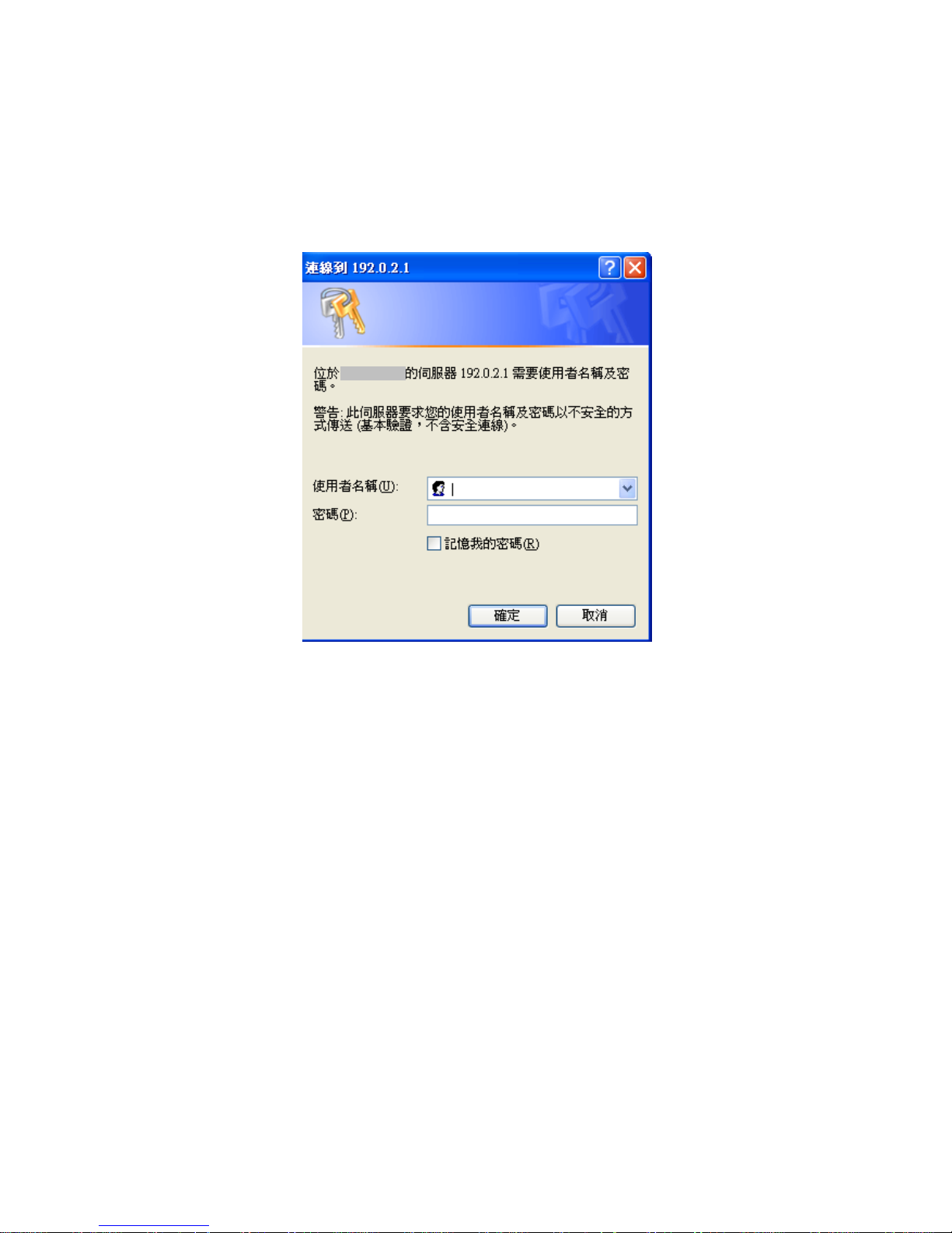
After the managed switch has been finished configuration the switch’s serial
interface, you can browse it. For instance, type http://192.168.1.1 in the address row
in a browser, it will show the following screen (see Fig.3-1) and ask you inputting
username and password in order to login and access authentication. The default
username and password are both ―admin‖. For the first time to use, please enter the
default username and password, then click the <Login> button. The login process
now is completed.
In this login menu, you have to input the complete username and password
respectively, the switch will not give you a shortcut to username automatically. This
looks inconvenient, but safer.
In the switch, it supports a simple user management function allowing only
one administrator to configure the system at the same time. If there are two or more
users using administrator’s identity, the switch will allow the only one who logins first
to configure the system. The rest of users, even with administrator’s identity, can
only monitor the system. For those who have no administrator’s identity, can only
monitor the system. There are only a maximum of three users able to login
simultaneously in the switch.
Note :When you login the swith WEB/CLI to manager.You must first type the
Username of the admin. Password was blank, so when you type after the end
Username, please press enter. Management page to enter WEB/CLI.
Note : AS LGS-2624C the function enable dhcp, so If you do not have DHCP
server to provide ip addressesto the switch, the Switch default ip 192.168.1.1
Note : When you login LGS-2624C switch Web UI management, you can use both
ipv4 ipv6 login to manage
To optimize the display effect, we recommend you use Microsoft IE 6.0 above,
Netscape V7.1 above or FireFox V1.00 above and have the resolution 1024x768.
The switch supported neutral web browser interface.
for example, left section is the whole function tree with web user interface
and we will travel it through this chapter.

Publication date: Aug., 2011
Revision A1
4
1. System
This chapter describes all of the basic configuration tasks which
includes the System Information and any manage of the Switch(e.g.
Time, Account, IP, Syslog and SNMP.)
1-1 System Information
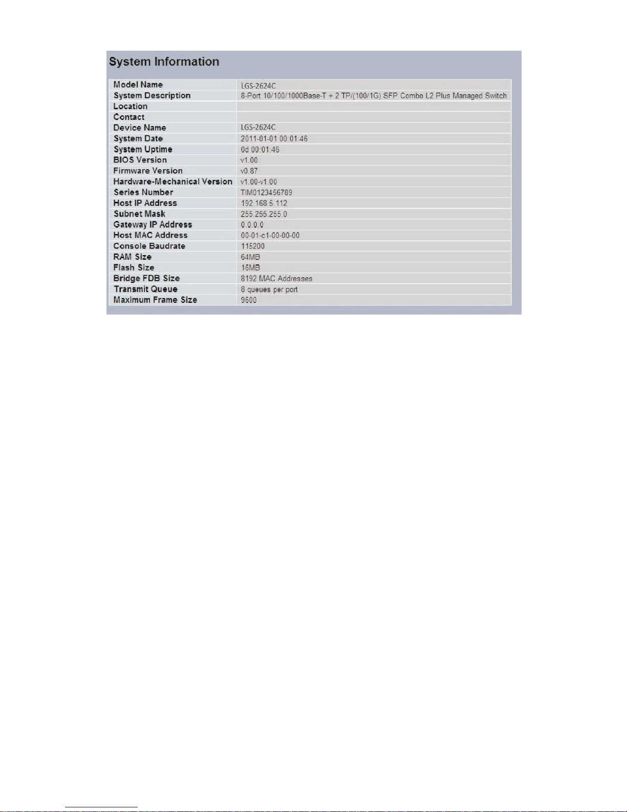
After you login, the switch shows you the system information . This page is
default and tells you the basic information of the system, including ―Model
Name‖, ―System Description‖, ―Contact‖, ―Device Name‖, ―System Up Time‖,
―BIOS Version‖, ―Firmware Version‖, ―Hardware-Mechanical Version‖, ―Serial
Number‖, ―Host IP Address‖, ―Host Mac Address‖, ―Device Port‖, ―RAM
Size‖ , ―Flash Size‖ and. With this information, you will know the software
version used, MAC address, serial number, how many ports good and so on.
This is helpful while malfunctioning.
1-1.1 Information
The switch system information is provided here.
Web interface
To configure System Information in the web interface:
1. Click SYSTEM, System, Information.
2. Specify the contact information for the system administrator
as well as the name and location of the switch. Also indicate
the local time zone by configuring the appropriate offset.
3. Click Refresh
Parameter description:
Contact
The system contact configured in Configuration System Information |
System Contact.
Name
The system name configured in Configuration System Information System
Name.
Location
The system location configured in Configuration System Information
System Location.
Chip ID
The Chip ID of this switch.
MAC Address
The MAC Address of this switch.
System Date
The current (GMT) system time and date. The system time is obtained
through the configured SNTP Server, if any.
System Uptime
The period of time the device has been operational.
Software Version
The software version of the switch.
Software Date
The date when the switch software was produced.

Publication date: Aug., 2011
Revision A1
1
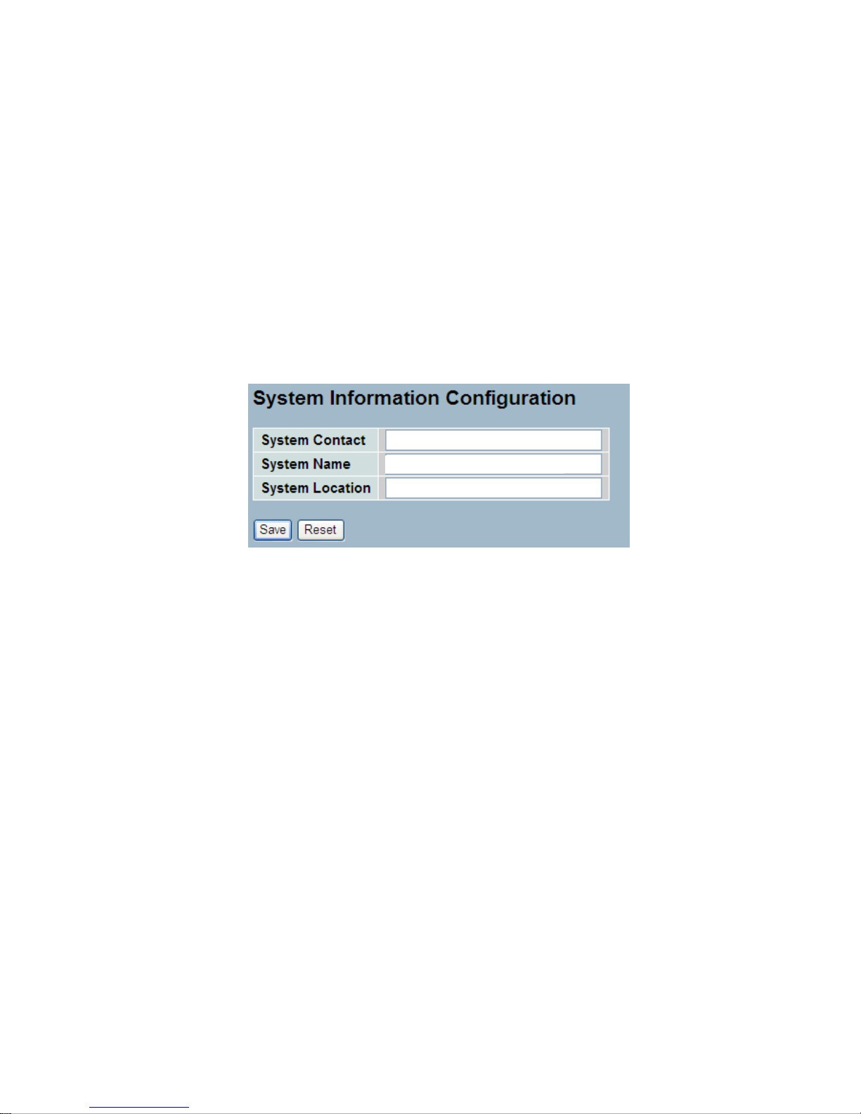
1-1.2 Configuration
You can identify the system by configuring the contact information, name,
and location of the switch.
Web interface
To configure System Information in the web interface:
1. Click System, System Information, Configuration.
2. Write System Contact , System Name, System Location information
in this page.
3. Click Save
Parameter description:
System Contact
The textual identification of the contact person for this managed node,
together with information on how to contact this person. The allowed
string length is 0 to 255, and the allowed content is the ASCII characters
from 32 to 126.
System Name
An administratively assigned name for this managed node. By convention,
this is the node's fully-qualified domain name. A domain name is a text
string drawn from the alphabet (A-Za-z), digits (0-9), minus sign (-). No
space characters are permitted as part of a name. The first character
must be an alpha character. And the first or last character must not be a
minus sign. The allowed string length is 0 to 255.
System Location
The physical location of this node(e.g., telephone closet, 3rd floor). The
allowed string length is 0 to 255, and the allowed content is the ASCII
characters from 32 to 126.
LGS-2624C

Publication date: Aug., 2011
Revision A1
1
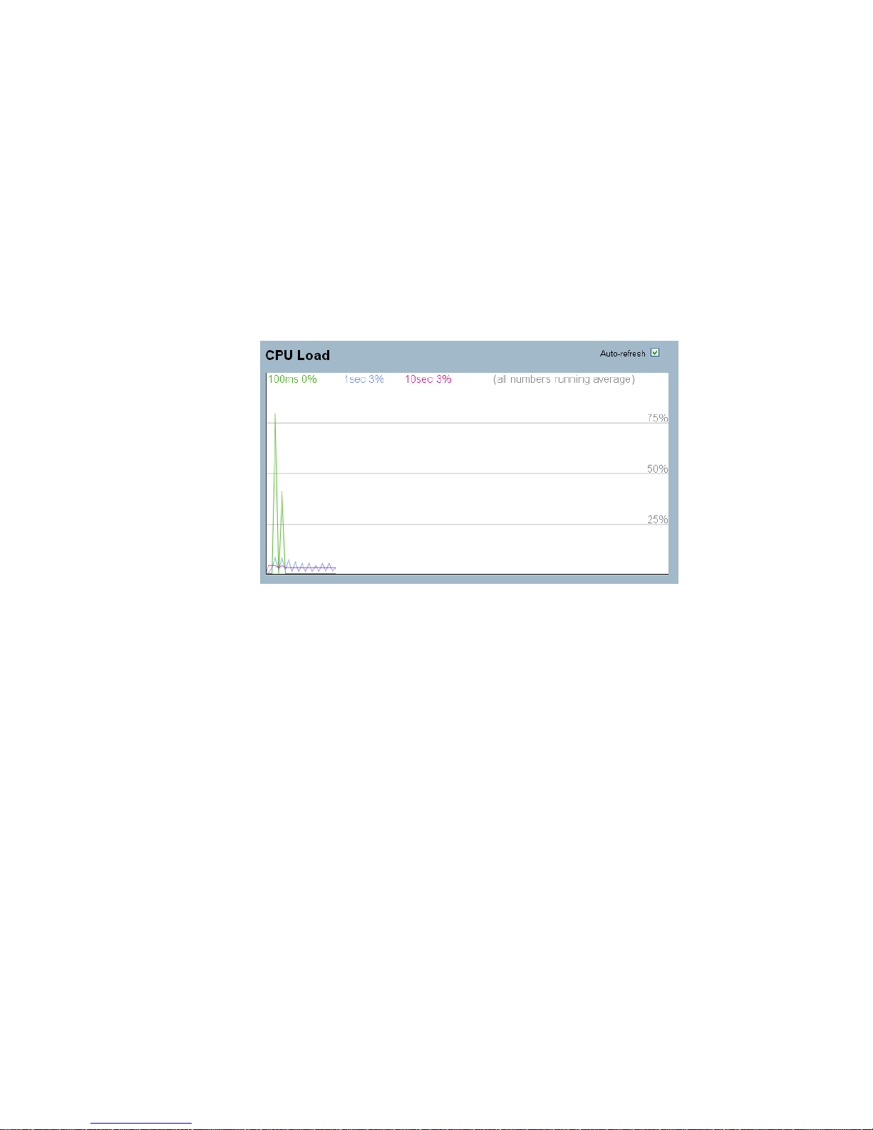
1-1.3 CPU Load
This page displays the CPU load, using an SVG graph
Web Interface
To configure System Information in the web interface:
1. Click System, System Information, CPU Load .
2. Display the CPU Load on the screen
3. Click Auto-refresh .
Parameter description:
The load is measured as averaged over the last 100ms, 1sec and 10
seconds intervals. The last 120 samples are graphed, and the last numbers
are displayed as text as well.
In order to display the SVG graph, your browser must support the SVG
format. Consult the SVG Wiki for more information on browser support.
Specifically, at the time of writing, Microsoft Internet Explorer will need to
have a plugin installed to support SVG.
Note :CPU Load is using SVG (Scalable Vector Graphics) to display the
chart and this feature is only available on MS IE 9.0 & above or Firefox v4.0
& above.
1-2 Time
This page configure the switch Time. Time configure is including Time
Configuration and NTP Configuration
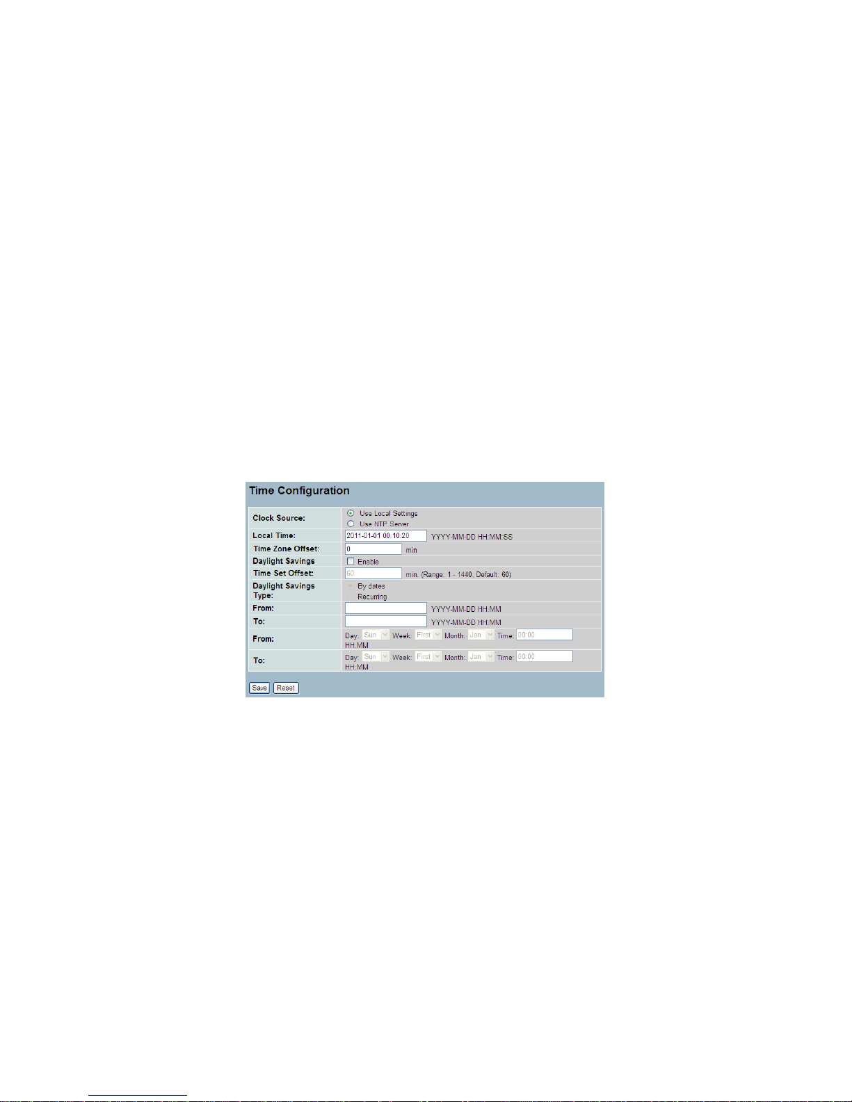
1-2.1 Manual
The switch provides manual and automatic ways to set the system time
via NTP. Manual setting is simple and you just input “Year”, “Month”,
“Day”, “Hour”, “Minute” and “Second” within the valid value range
indicated in each item.
Web Interface
To configure Time in the web interface:
1. Click Time , Manual.
2. Specify the Time parameter in manual parameters.
3. Click Save.
Parameter description:
Local Time:
Show the current time of the system.
Timezone Offset
Provide the timezone offset relative to UTC/GMT. The offset
is given in minutes east of GMT. The valid range is from -720
to 720 minutes.

Daylight Saving:
Daylight saving is adopted in some countries. If set, it will adjust the time
lag or in advance in unit of hours, according to the starting date and the
ending date. For example, if you set the day light saving to be 1 hour.
When the time passes over the starting time, the system time will be
increased one hour after one minute at the time since it passed over. And
when the time passes over the ending time, the system time will be
decreased one hour after one minute at the time since it passed over.
The switch supports valid configurable day light saving time is –5 ~ +5
step one hour. The zero for this parameter means it need not have to
adjust current time, equivalent to in-act daylight saving. You don’t have to
set the starting/ending date as well. If you set daylight saving to be nonzero, you have to set the starting/ending date as well; otherwise, the
daylight saving function will not be activated.
.
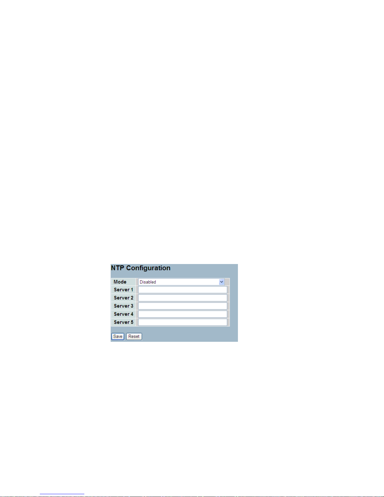
1-2.2 NTP
NTP is Network Time Protocol and is used to sync the network time based
Greenwich Mean Time (GMT). If use the NTP mode and select a built-in
NTP time server or manually specify an user-defined NTP server as well as
Time Zone, the switch will sync the time in a short after pressing <Apply>
button. Though it synchronizes the time automatically, NTP does not update
the time periodically without user’s processing.
Time Zone is an offset time off GMT. You have to select the time zone first
and then perform time sync via NTP because the switch will combine this
time zone offset and updated NTP time to come out the local time,
otherwise, you will not able to get the correct time. The switch supports
configurable time zone from –12 to +13 step 1 hour.
Default Time zone: +8 Hrs.
Web Interface
To configure Time in the web interface:
1. Click SYSTEM, NTP.
2. Specify the Time parameter in manual parameters.
3. Click Save.
Parameter description:
Mode
Indicates the NTP mode operation. Possible modes are:
Enabled: Enable NTP mode operation. When NTP mode operationis
enabled, the agent forwards NTP messages between the clients and the
server when they are not on the same subnet domain.
Disabled: Disable NTP mode operation.

Server 1to 5
Provide the NTP IPv4 or IPv6 address of this switch. IPv6 address is in
128-bit records represented as eight fields of up to four hexadecimal digits
with a colon separating each field (:). For example,
'fe80::215:c5ff:fe03:4dc7'. The symbol '::' is a special syntax that can be
used as a shorthand way of representing multiple 16-bit groups of
contiguous zeros; but it can only appear once.It can also represent a legally
valid IPv4 address.For example, '::192.1.2.34'.
Buttons
These buttons are displayed on the NTP page:
Save – Click to save changes.
Reset - Click to undo any changes made locally and revert to previously
saved values.
1-3 Account
In this function, only administrator can create, modify or delete the
username and password. Administrator can modify other guest identities’
password without confirming the password but it is necessary to modify the
administrator-equivalent identity. Guest-equivalent identity can modify his
password only. Please note that you must confirm administrator/guest
identity in the field of Authorization in advance before configuring the
username and password. Only one administrator is allowed to exist and
unable to be deleted. In addition, up to 4 guest accounts can be created.
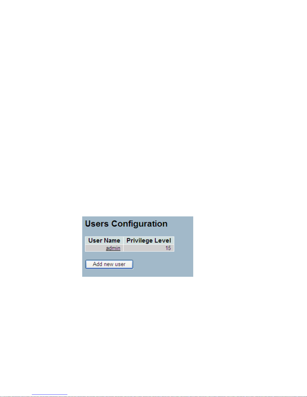
1-3.1 Users
This page provides an overview of the current users. Currently the only way
to login as another user on the web server is to close and reopen the
browser
Web Interface
To configure Account in the web interface:
1. Click SYSTEM, Account, Users.
2. Specify the User Name parameter.
3. Click Save.
Parameter description:
User Name
The name identifying the user. This is also a link to Add/Edit User.

Privilege Level
The privilege level of the user. The allowed range is 1 to 15. If the privilege
level value is 15, it can access all groups, i.e. that is granted the fully control
of the device. But others value need to refer to each group privilege level.
User's privilege should be same or greater than the group privilege level to
have the access of that group. By default setting, most groups privilege
level 5 has the read-only access and privilege level 10 has the read-write
access. And the system maintenance (software upload, factory defaults and
etc.) need user privilege level 15. Generally, the privilege level 15 can be
used for an administrator account, privilege level 10 for a standard user
account and privilege level 5 for a guest account.
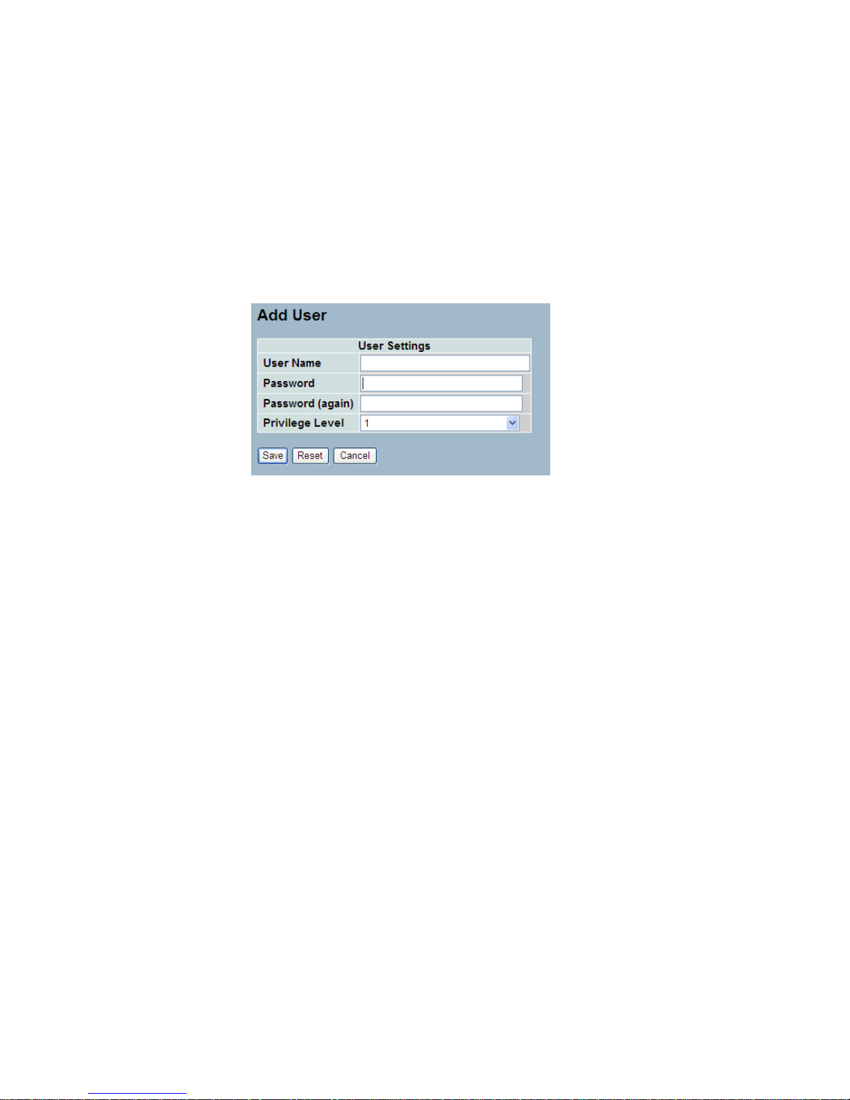
1-3.1.1 Add User
This page configures a user.The switch provide add different user.
Web Interface
To configure Account in the web interface:
1. Click SYSTEM, Account, Users,Add new user
2. Specify the User Name, Password parameter.
3. Click Save.
Parameter description:
User Name
The name identifying the user.
Password
The password of the user.
Privilege Level
The privilege level of the user. The allowed range is 1 to 15. If the
privilege level value is 15, it can access all groups, i.e. that is granted the
fully control of the device. But others value need to refer to each group
privilege level. User's privilege should be same or greater than the group
privilege level to have the access of that group. By default setting, most
groups privilege level 5 has the read-only access and privilege level 10 has
the read-write access. And the system maintenance (software upload,
factory defaults and etc.) need user privilege level 15. Generally, the
privilege level 15 can be used for an administrator account, privilege level
10 for a standard user account and privilege level 5 for a guest account.
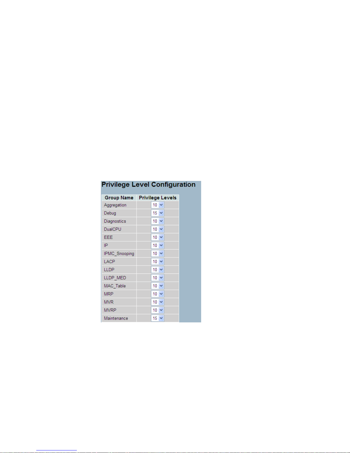
1-3.1.2 Privitege Level
This page provides an overview of the privilege levels. The switch provides
user set Account, Aggregation,Diagnostics,EEE,GARP,GVRP,IP, IPMC
Snooping LACP LLDP LLDP MED MAC Table MRP MVR MVRP
Maintenance Mirroring POE Ports Private VLANs QoS SMTP SNMP
Security Spanning Tree System Trap Event VCL VLANs Voice VLAN
Privilege Levels form 1 to 15 .
Web Interface
To configure Privilege Level in the web interface:
1. Click SYSTEM, Account, Privilege Level.
2. Specify the Privilege parameter.
3. Click Save.

Parameter description:
Group Name
The name identifying the privilege group. In most cases, a privilege level
group consists of a single module (e.g. LACP, RSTP or QoS), but a few of
them contains more than one. The following description defines these
privilege level groups in details:
System: Contact, Name, Location, Timezone, Log.
Security: Authentication, System Access Management, Port (contains
Dot1x port, MAC based and the MAC Address Limit), ACL, HTTPS, SSH,
ARP Inspection and IP source guard.
IP: Everything except 'ping'.
Port: Everything except 'VeriPHY'.
Diagnostics: 'ping' and 'VeriPHY'.
Maintenance: CLI- System Reboot, System Restore Default, System
Password, Configuration Save, Configuration Load and Firmware Load.
Web- Users, Privilege Levels and everything in Maintenance.
Debug: Only present in CLI.
Privilege Levels
Every group has an authorization Privilege level for the following sub
groups: configuration read-only, configuration/execute read-write,
status/statistics read-only, status/statistics read-write (e.g. for clearing of
statistics). User Privilege should be same or greater than the
authorization Privilege level to have the access to that group.

1-4 IP
IP is an acronym for Internet Protocol. It is a protocol used for
communicating data across an internet network.
IP is a "best effort" system, which means that no packet of information sent
over is assured to reach its destination in the same condition it was sent.
Each device connected to a Local Area Network (LAN) or Wide Area
Network (WAN) is given an Internet Protocol address, and this IP address is
used to identify the device uniquely among all other devices connected to
the extended network.
The current version of the Internet protocol is IPv4, which has 32-bits
Internet Protocol addresses allowing for in excess of four billion unique
addresses. This number is reduced drastically by the practice of
webmasters taking addresses in large blocks, the bulk of which remain
unused. There is a rather substantial movement to adopt a new version of
the Internet Protocol, IPv6, which would have 128-bits Internet Protocol
addresses. This number can be represented roughly by a three with thirtynine zeroes after it. However, IPv4 is still the protocol of choice for most of
the Internet.
1-4.1 IPV4
The IPv4 address for the switch could be obtained via DHCP Server for
VLAN 1. To manually configure an address, you need to change the
switch's default settings to values that are compatible with your network.
You may also need to a establish a default gateway between the switch and
management stations that exist on another network segment.
Configure the switch-managed IP information on this page
The Configured column is used to view or change the IP configuration.
The Current column is used to show the active IP configuration.
Web Interface
To configure an IP address in the web interface:
1. Click System, IP Configuration.
2. Specify the IPv4 settings, and enable DNS proxy service if required.
3. Click Save.
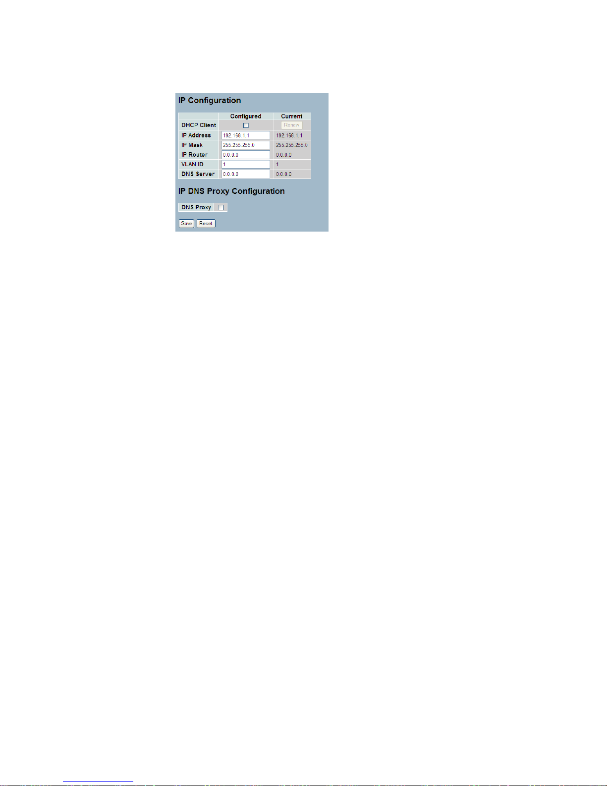
Parameter description:
DHCP Client
Enable the DHCP client by checking this box. If DHCP fails and the
configured IP address is zero, DHCP will retry. If DHCP fails and the
configured IP address is non-zero, DHCP will stop and the configured IP
settings will be used. The DHCP client will announce the configured System
Name as hostname to provide DNS lookup.
IP Address
Provide the IP address of this switch in dotted decimal notation.
IP Mask
Provide the IP mask of this switch dotted decimal notation.
IP Router
Provide the IP address of the router in dotted decimal notation.
SNTP Server
Provide the IP address of the SNTP Server in dotted decimal notation.
DNS Server
Provide the IP address of the DNS Server in dotted decimal notation.
VLAN ID
Provide the managed VLAN ID. The allowed range is 1 to 4095.
DNS Proxy
When DNS proxy is enabled, DUT will relay DNS requests to the current
configured DNS server on DUT, and reply as a DNS resolver to the client
device on the network.
1-4.2 IPV6
This section describes how to configure the switch-managed IPv6
information. The Configured column is used to view or change the IPv6
configuration. And the Current column is used to show the active IPv6
configuration.
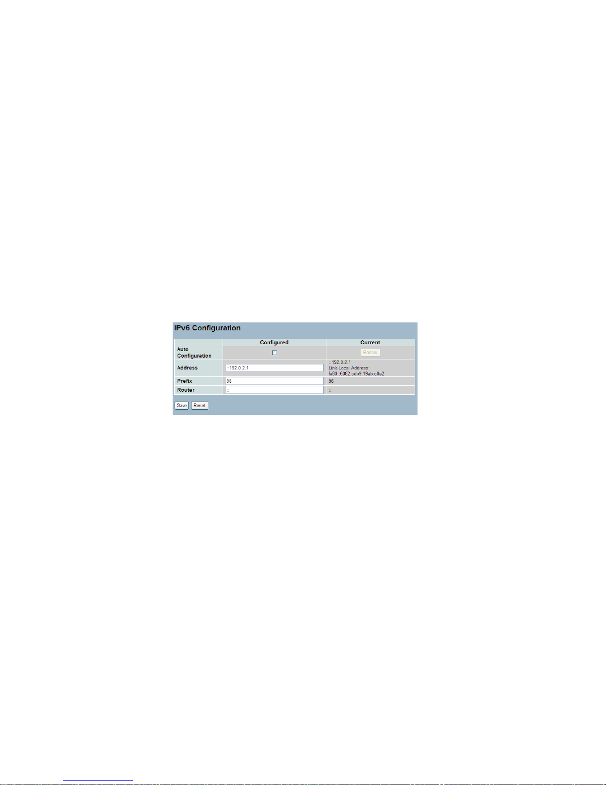
Configure the switch-managed IPv6 information on this page.
The Configured column is used to view or change the IPv6 configuration.
The Current column is used to show the active IPv6 configuration.
Web Interface
To configure Management IPv6 of the switch in the web interface:
1. Click System, IPv6 Configuration.
2. Specify the IPv6 settings, and enable Auto Configuration service
if required.
3. Click Save.
Parameter description:
Auto Configuration
Enable IPv6 auto-configuration by checking this box. If fails, the configured
IPv6 address is zero. The router may delay responding to a router
solicitation for a few seconds, the total time needed to complete autoconfiguration can be significantly longer.
Address
Provide the IPv6 address of this switch. IPv6 address is in 128-bit records
represented as eight fields of up to four hexadecimal digits with a colon
separating each field (:). For example, 'fe80::215:c5ff:fe03:4dc7'. The
symbol '::' is a special syntax that can be used as a shorthand way of
representing multiple 16-bit groups of contiguous zeros; but it can only
appear once. It can also represent a legally valid IPv4 address. For
example, '::192.1.2.34'.
Prefix
Provide the IPv6 Prefix of this switch. The allowed range is 1 to 128.

Router
Provide the IPv6 gateway address of this switch. IPv6 address is in 128-bit
records represented as eight fields of up to four hexadecimal digits with a
colon separating each field (:). For example, 'fe80::215:c5ff:fe03:4dc7'. The
symbol '::' is a special syntax that can be used as a shorthand way of
representing multiple 16-bit groups of contiguous zeros; but it can only
appear once. It can also represent a legally valid IPv4 address. . For
example, '::192.1.2.34'.

1-5 Syslog
The Syslog is a standard for logging program messages . It allows
separation of the software that generates messages from the system that
stores them and the software that reports and analyzes them. It can be
used as well a generalized informational, analysis and debugging messages.
It is supported by a wide variety of devices and receivers across multiple
platforms.
1-5.1 Configuration
This section describes how to configure the system log and provide a wide
variety of devices and receivers across multiple platforms.
Web Interface
To configure Syslog configuration in the web interface:
1. Click SYSTEM, Syslog.
2. Specify the syslog parameters includes IP Address of Syslog server
and Port number.
3. Evoke the Sylog to enable it.
4. Click Save.
Parameter description:
Server Mode
Indicates the server mode operation. When the mode operation is enabled,
the syslog message will send out to syslog server. The syslog protocol is
based on UDP communication and received on UDP port 514 and the
syslog server will not send acknowledgments back sender since UDP is a
connectionless protocol and it does not provide acknowledgments. The
syslog packet will always send out even if the syslog server does not exist.
Possible modes are:
Enabled: Enable server mode operation.
Disabled: Disable server mode operation.

Server Address
Indicates the IPv4 host address of syslog server. If the switch provide DNS
feature, it also can be a host name.
Syslog Level
Indicates what kind of message will send to syslog server. Possible modes
are:
Emerg: send Emerg
Alert: send Emerg, Alert
Crit: send Emerg, Alert, Crit
Error: send Emerg, Alert, Crit, Error
Warning: Send warnings
Notice: send Emerg, Alert, Crit, Error, Warning, Notice
Info: send Emerg, Alert, Crit, Error, Warning, Notice, Info
Debug : send everything, i.e. all

1-5.2 Log
This section describes that display the system log information of the switch
Web Interface
To display the log configuration in the web interface:
1. Click Syslog, Log.
2. Display the log information.
Parameter description:
ID
ID (>= 1) of the system log entry.
Level
level of the system log entry. The following level types are supported:
Information level of the system log.Warning: Warning level of the system log.
Error: Error level of the system log.All: All levels.
Time
The time of the system log entry.
Message
The message of the system log entry.

1-5.3 Detailed Log
This section describes that display the detailed log information of the
switch
Web Interface
To display the detailed log configuration in the web interface:
1. Click Syslog, Detailed Log.
2. Display the log information.
Parameter description:
ID
The ID (>= 1) of the system log entry.
Message
The detailed message of the system log entry.

1-6 SNMP
Any Network Management System (NMS) running the Simple Network
Management Protocol (SNMP) can manage the Managed devices
equipped with SNMP agent, provided that the Management Information
Base (MIB) is installed correctly on the managed devices. The SNMP is a
protocol that is used to govern the transfer of information between SNMP
manager and agent and traverses the Object Identity (OID) of the
management Information Base (MIB), described in the form of SMI syntax.
SNMP agent is running on the switch to response the request issued by
SNMP manager.
Basically, it is passive except issuing the trap information. The switch
supports a switch to turn on or off the SNMP agent. If you set the field
SNMP ―Enable‖, SNMP agent will be started up. All supported MIB OIDs,
including RMON MIB, can be accessed via SNMP manager. If the field
SNMP is set ―Disable‖, SNMP agent will be de-activated, the related
Community Name, Trap Host IP Address, Trap and all MIB counters will be
ignored.
1-6.1 System
This section describes how to configure SNMP System on the switch. This
function is used to configure SNMP settings, community name, trap host
and public traps as well as the throttle of SNMP. A SNMP manager must
pass the authentication by identifying both community names, then it can
access the MIB information of the target device. So, both parties must
have the same community name. Once completing the setting, click
<Apply> button, the setting takes effect.
Web Interface
To display the configure SNMP System in the web interface:
1. Click SNMP, System.
2. Evoke SNMP State to enable or disable the SNMP function .
3. Specify the Engine ID
4. Click Apply.

Parameter description:
These parameters are displayed on the SNMP System Configuration page:]
SNMP State -The term SNMP here The term SNMP here is used for the
activation or de-activation of SNMP.
Enable: Enable SNMP state operation.
Disable: Disable SNMP state operation.
Default: Enable.
Engine ID - SNMPv3 engine ID. syntax: 0-9,a-f,A-F, min 5 octet,
max 32 octet, fifth octet can't input 00. IF change the Engine ID
that will clear all original user.

1-6.2 Communities
The function is used to configure SNMPv3 communities. The Community
and UserName is unique. To create a new community account, please
check <Add new community> button, and enter the account information
then check <Save>. Max Group Number : 4.
Web Interface
To display the configure SNMP Communities in the web interface:
1. Click SNMP, Communities.
2. Click Add new community.
3. Specify the SNMP communities parameters.
4. Click Save.
5. If you want to modify or clear the setting then click Reset.
Parameter description:
Delete
Check to delete the entry. It will be deleted during the next save.
Community
Indicates the community access string to permit access to SNMPv3 agent.
The allowed string length is 1 to 32, and the allowed content is ASCII
characters from 33 to 126. The community string will be treated as security
name and map a SNMPv1 or SNMPv2c community string.
Source IP
Indicates the SNMP access source address. A particular range of source
addresses can be used to restrict source subnet when combined with
source mask.
Source Mask
Indicates the SNMP access source address mask

1-6.3 Users
The function is used to configure SNMPv3 user. The Entry index key is
UserName. To create a new UserName account, please check <Add new
user> button, and enter the user information then check <Save>. Max
Group Number : 10.
Web Interface
To display the configure SNMP Users in the web interface:
1. Click SNMP, Users.
2. Specify the Privilege parameter.
3. Click Save.
Parameter description:
Delete
Check to delete the entry. It will be deleted during the next save.
Engine ID
An octet string identifying the engine ID that this entry should belong to. The
string must contain an even number(in hexadecimal format) with number of
digits between 10 and 64, but all-zeros and all-'F's are not allowed. The
SNMPv3 architecture uses the User-based Security Model (USM) for
message security and the View-based Access Control Model (VACM) for
access control. For the USM entry, the usmUserEngineID and Usm User
Name are the entry's keys. In a simple agent, usmUserEngineID is always
that agent's own snmpEngineID value. The value can also take the value of
the snmpEngineID of a remote SNMP engine with which this user can
communicate. In other words, if user engine ID equal system engine ID
then it is local user; otherwise it's remote user.
User Name
A string identifying the user name that this entry should belong to. The
allowed string length is 1 to 32, and the allowed content is ASCII characters
from 33 to 126.

Security Level
Indicates the security model that this entry should belong to. Possible
security models are:
NoAuth, NoPriv: No authentication and no privacy.
Auth, NoPriv: Authentication and no privacy.
Auth, Priv: Authentication and privacy.
The value of security level cannot be modified if entry already exists. That
means it must first be ensured that the value is set correctly.
Authentication Protocol
Indicates the authentication protocol that this entry should belong to.
Possible authentication protocols are:
None: No authentication protocol.
MD5: An optional flag to indicate that this user uses MD5 authentication
protocol.
SHA: An optional flag to indicate that this user uses SHA authentication
protocol.
The value of security level cannot be modified if entry already exists. That
means must first ensure that the value is set correctly.
Authentication Password
A string identifying the authentication password phrase. For MD5
authentication protocol, the allowed string length is 8 to 32. For SHA
authentication protocol, the allowed string length is 8 to 40. The allowed
content is ASCII characters from 33 to 126.
Privacy Protocol
Indicates the privacy protocol that this entry should belong to. Possible
privacy protocols are:
None: No privacy protocol.
DES: An optional flag to indicate that this user uses DES authentication
protocol.
Privacy Password
A string identifying the privacy password phrase. The allowed string length
is 8 to 32, and the allowed content is ASCII characters from 33 to 126.

1-6.4 Groups
The function is used to configure SNMPv3 group. The Entry index key are
Security Model and Security Name. To create a new group account, please
check <Add new group> button, and enter the group information then check
<Save>. Max Group Number : v1: 2, v2: 2, v3:10.
Web Interface
To display the configure SNMP Groups in the web interface:
1. Click SNMP, Groups.
2. Specify the Privilege parameter.
3. Click Save.
Parameter description:
Delete
Check to delete the entry. It will be deleted during the next save.
Security Model
Indicates the security model that this entry should belong to. Possible
security models are:
v1: Reserved for SNMPv1.
v2c: Reserved for SNMPv2c.
usm: User-based Security Model (USM).
Security Name
A string identifying the security name that this entry should belong to. The
allowed string length is 1 to 32, and the allowed content is ASCII characters
from 33 to 126.
Group Name
A string identifying the group name that this entry should belong to. The
allowed string length is 1 to 32, and the allowed content is ASCII characters
from 33 to 126.

1-6.5 Views
The function is used to configure SNMPv3 view. The Entry index key are
OID Subtree and View Name. To create a new view account, please check
<Add new view> button, and enter the view information then check <Save>.
Max Group Number : 28.
Configure SNMPv3 view table on this page. The entry index keys are View
Name and OID Subtree.
Web Interface
1. Click SNMP, Views.
2. Click Add new View.
3. Specify the SNMP View parameters.
4. Click Save.
5. If you want to modify or clear the setting then click Reset.
Parameter description:
Delete
Check to delete the entry. It will be deleted during the next save.
View Name
A string identifying the view name that this entry should belong to. The
allowed string length is 1 to 32, and the allowed content is ASCII characters
from 33 to 126.
View Type
Indicates the view type that this entry should belong to. Possible view types
are:
included: An optional flag to indicate that this view subtree should be
included.
excluded: An optional flag to indicate that this view subtree should be
excluded.
In general, if a view entry's view type is 'excluded', there should be another
view entry existing with view type as 'included' and it's OID subtree should
overstep the 'excluded' view entry.

OID Subtree
The OID defining the root of the subtree to add to the named view. The
allowed OID length is 1 to 128. The allowed string content is digital number
or asterisk(*).

1-6.6 Access
The function is used to configure SNMPv3 accesses. The Entry index key
are Group Name, Security Model and Security level. To create a new
access account, please check <Add new access> button, and enter the
access information then check <Save>. Max Group Number : 14
Web Interface
To display the configure SNMP Access in the web interface:
1. Click SNMP, Accesses.
2. Click Add new Access.
3. Specify the SNMP Access parameters.
4. Click Save.
5. If you want to modify or clear the setting then click Reset.
.
Parameter description:
Delete
Check to delete the entry. It will be deleted during the next save.
Group Name
A string identifying the group name that this entry should belong to. The
allowed string length is 1 to 32, and the allowed content is ASCII characters
from 33 to 126.
Security Model
Indicates the security model that this entry should belong to. Possible
security models are:
any: Any security model accepted(v1|v2c|usm).
v1: Reserved for SNMPv1.
v2c: Reserved for SNMPv2c.
usm: User-based Security Model (USM).
Security Level
Indicates the security model that this entry should belong to. Possible
security models are:
NoAuth, NoPriv: No authentication and no privacy.
Auth, NoPriv: Authentication and no privacy.
Auth, Priv: Authentication and privacy.

Read View Name
The name of the MIB view defining the MIB objects for which this request
may request the current values. The allowed string length is 1 to 32, and
the allowed content is ASCII characters from 33 to 126. Write View Name
The name of the MIB view defining the MIB objects for which this request
may potentially set new values. The allowed string length is 1 to 32, and the
allowed content is ASCII characters from 33 to 126.

1-6.7 Tarp
The function is used to configure SNMP trap. To create a new trap account,
please check <No number> button, and enter the trap information then check
<Apply>. Max Group Number : 6.
Web Interface
To configure SNMP Trap setting:
1. Click SNMP, Trap .
2. Display the SNMP Trap Hosts information table.
3. Choice a entry to display and modify the detail parameters or click
delete button to delete the trap hosts entry.

Parameters description:
Delete:
Check <Delete> entry then check <Save> button, the entry will be delete.
Trap Version:
You may choose v1, v2c or v3 trap.
Server IP:
SNMP Host IP address.
UDP Port:
Port number. Default: 162
Community / Security Name:
The length of ―Community / Security Name‖ string is restricted to 1-32.
Security Level:
Indicates what kind of message will send to Security Level.
Possible modes are:
Info: Send informations, warnings and errors.
Warning: Send warnings and errors.
Error: Send errors.
Security Level:
There are three kinds of choices.
NoAuth, NoPriv: No authentication and no privacy.
Auth, NoPriv: Authentication and no privacy.
Auth, Priv: Authentication and privacy.
Authentication Protocol:
You can choose MD5 or SHA for authentication.
Authentication Password:
The length of 'MD5 Authentication Password' is restricted to 8 – 32.
The length of 'SHA Authentication Password' is restricted to 8 – 40.
Privacy Protocol:
You can set DES encryption for UserName.
Privacy Password:
The length of ' Privacy Password ' is restricted to 8 – 32.

2. Configuration
This chapter describes all of the basic network configuration tasks
which includes the Ports, Layer 2 network protocol (e.g. VLANs, QoS,
IGMP, ACLs etc.) and any setting of the Switch.
2-1 Port
The section describes to configure the Port detail parameters of the switch.
Others you could using the Port configure to enable or disable the Port of
the switch. Monitor the ports content or status in the function.
2-1.1 Configuration
This chapter describes how to view the current port configuration and how to
configure ports to non-default settings, including
Linkup/Linkdown
Speed (Current and configured)
Flow Control (Current Rx, Current Tx and Configured)
Maximum Frame Size
Excessive Collision Mode
Power Control.
Web Interface
To configure an Current Port Configuration in the web interface:
1. Click Configuration, Port, then Configuration
2. Specify the Speed Configured, Flow Control , Maximum Frame sze ,
Excessive Collision mode and Power Control.
3. Click Save.

Parameter description:
Port
This is the logical port number for this row.
Link
The current link state is displayed graphically. Green indicates the link is up
and red that it is down.
Current Link Speed
Provides the current link speed of the port.
Configured Link Speed
Select any available link speed for the given switch port.
Auto Speed selects the highest speed that is compatible with a link partner.
Disabled disables the switch port operation.
Flow Control
When Auto Speed is selected on a port, this section indicates the flow
control capability that is advertised to the link partner. When a fixed-speed
setting is selected, that is what is used. The Current Rx column indicates
whether pause frames on the port are obeyed, and the Current Tx column
indicates whether pause frames on the port are transmitted. The Rx and Tx
settings are determined by the result of the last Auto-Negotiation.
Check the configured column to use flow control. This setting is related to
the setting for Configured Link Speed.
Maximum Frame Size
Enter the maximum frame size allowed for the switch port, including FCS.
Excessive Collision Mode
Configure port transmit collision behavior.
Discard: Discard frame after 16 collisions (default).
Restart: Restart backoff algorithm after 16 collisions.
Power Control
The Usage column shows the current percentage of the power consumption
per port. The Configured column allows for changing the power savings
mode parameters per port.
Disabled: All power savings mechanisms disabled.
ActiPHY: Link down power savings enabled.
PerfectReach: Link up power savings enabled.
Enabled: Both link up and link down power savings enabled.

2-1.2 Port Description
The section describes to configure the Port’s alias or any descriptions for
the Port Identity. It provides user to write down an alphanumeric string
describing the full name and version identification for the system’s hardware
type, software version, and networking application
Web Interface
To configure an Port Description in the web interface:
1. Click Configuration, Port, then Port Description
2. Specify the detail Port alias or description an alphanumeric string
describing the full name and version identification for the system’s
hardware type, software version, and networking application.
3. Click Save.

2-1.3 Traffic Overview
The section describes to the Port statistics information and provides
overview of general traffic statistics for all switch ports. The ports belong to
the currently selected stack unit, as reflected by the page header
Web Interface
To Display the Port Statistics Overview in the web interface:
1. Click Configuration, Port, then Traffic Overview
2. If you want to auto-refresh then you need to evoke the ―Auto-refresh‖ .
3. Click ― Refresh― to refresh the port statistics or clear all information
when you click ― Clear‖.
Parameter description:
Port
The logical port for the settings contained in the same row.
Packets
The number of received and transmitted packets per port.
Bytes
The number of received and transmitted bytes per port.
Errors
The number of frames received in error and the number of incomplete
transmissions per port.
Drops
The number of frames discarded due to ingress or egress congestion.
Filtered
The number of received frames filtered by the forwarding

2-1.4 Detailed Statistics
The section describes how to provide detailed traffic statistics for a specific
switch port. Use the port select box to select which switch port details to
display. The selected port belongs to the currently selected stack unit, as
reflected by the page header.
The displayed counters are the totals for receive and transmit, the size
counters for receive and transmit, and the error counters for receive and
transmit.
Web Interface
To Display the per Port detailed Statistics Overview in the web interface:
1. Click Configuration, Port, then Detailed Port Statistics
2. Scroll the Port Index to select which port you want to show the detailed
Port statistics overview‖ .
3. If you want to auto-refresh the information then you need to evoke the
―Auto-refresh‖.
4. Click ― Refresh― to refresh the port detailed statistics or clear all
information when you click ― Clear‖.
Parameter description:
Receive Total and Transmit Total
Rx and Tx Packets
The number of received and transmitted (good and bad) packets.
Rx and Tx Octets
The number of received and transmitted (good and bad) bytes. Includes
FCS, but excludes framing bits.

Rx and Tx Unicast
The number of received and transmitted (good and bad) unicast packets.
Rx and Tx Multicast
The number of received and transmitted (good and bad) multicast packets.
Rx and Tx Broadcast
The number of received and transmitted (good and bad) broadcast packets.
Rx and Tx Pause
A count of the MAC Control frames received or transmitted on this port that
have an opcode indicating a PAUSE operation.
Receive and Transmit Size Counters
The number of received and transmitted (good and bad) packets split into
categories based on their respective frame sizes.
Receive and Transmit Queue Counters
The number of received and transmitted packets per input and output queue.
Receive Error Counters
Rx Drops
The number of frames dropped due to lack of receive buffers or egress
congestion.
Rx CRC/Alignment
The number of frames received with CRC or alignment errors.
Rx Undersize
The number of short 1 frames received with valid CRC.
Rx Oversize
The number of long 2 frames received with valid CRC.
Rx Fragments
The number of short 1 frames received with invalid CRC.
Rx Jabber
The number of long 2 frames received with invalid CRC.
Rx Filtered
The number of received frames filtered by the forwarding process.
Short frames are frames that are smaller than 64 bytes.
Long frames are frames that are longer than the configured maximum frame
length for this port.

Transmit Error Counters
Tx Drops
The number of frames dropped due to output buffer congestion.
Tx Late/Exc. Coll.
The number of frames dropped due to excessive or late collisions.

2-1.5 Qos Statistics
The section describes that switch could display the QoS detailed Queuing
counters for a specific switch port. for the different queues for all switch
ports. The ports belong to the currently selected stack unit, as reflected by
the page header.
Web Interface
To Display the Queueing Counters in the web interface:
1. Click Configuration, Port, then QoS Statistics
2. If you want to auto-refresh the information then you need to evoke the
―Auto-refresh‖.
3. Click ― Refresh― to refresh the Queueing Counters or clear all information
when you click ― Clear‖.
Parameter description:
Port
The logical port for the settings contained in the same row.
Low Queue
There are 4 QoS queues per port with strict or weighted queue scheduling.
This is the lowest priority queue.
Normal Queue
This is the normal priority queue of the 4 QoS queues. It has higher priority
than the "Low Queue".
Medium Queue
This is the medium priority queue of the 4 QoS queues. It has higher priority
than the "Normal Queue".
High Queue
This is the highest priority queue of the 4 QoS queues.
Received/Transmitted
The number of received and transmitted packets per queue.

Port
The logical port for the settings contained in the same row.
Qn
There are ? QoS queues per port. Q0 is the lowest priority queue.
Rx/Tx
The number of received and transmitted packets per queue.

2-1.6 SFP Information
The section describes that switch could display the SFP module detail
information which you connect it to the switch. The information includes:
Connector type, Fiber type, wavelength, banud rate and Vendor OUI etc.
Web Interface
To Display the SFP information in the web interface:
1. Click Configuration, Port, then SFP Information
2. To display the SFP Information.
Parameter description:
Connector Type:
Display the connector type, for instance, UTP, SC, ST, LC and so on.
Fiber Type:
Display the fiber mode, for instance, Multi-Mode, Single-Mode.
Tx Central Wavelength:
Display the fiber optical transmitting central wavelength, for instance,
850nm, 1310nm, 1550nm and so on.
Baud Rate:
26

Display the maximum baud rate of the fiber module supported, for instance,
10M, 100M, 1G and so on.
Vendor OUI:
Display the Manufacturer's OUI code which is assigned by IEEE.
Vendor Name:
Display the company name of the module manufacturer.
Vendor P/N:
Display the product name of the naming by module manufacturer.
Vendor Rev (Revision):
Display the module revision.
Vendor SN (Serial Number):
Show the serial number assigned by the manufacturer.
Date Code:
Show the date this SFP module was made.
Temperature:
Show the current temperature of SFP module.
Vcc:
Show the working DC voltage of SFP module.
Mon1(Bias) mA:
Show the Bias current of SFP module.
Mon2(TX PWR):
Show the transmit power of SFP module.
Mon3(RX PWR):
Show the receiver power of SFP module.

2-1.7 EEE
The section which allows the user to inspect and configure the current EEE
port settings.
EEE is a power saving option that reduces the power usage when there is
very low traffic utilization (or no traffic).
EEE works by powering down circuits when there is no traffic. When a port
gets data to be transmitted all circuits are powered up. The time it takes to
power up the circuits is named wakeup time. The default wakeup time is 17
us for 1Gbit links and 30 us for other link speeds. EEE devices must agree
upon the value of the wakeup time in order to make sure that both the
receiving and transmitting device has all circuits powered up when traffic is
transmitted. The devices can exchange information about the devices
wakeup time using the LLDP protocol.
For maximizing the power saving, the circuit isn't started at once transmit
data are ready for a port, but is instead queued until 3000 bytes of data are
ready to be transmitted. For not introducing a large delay in case that data
less then 3000 bytes shall be transmitted, data are always transmitted after
48 us, giving a maximum latency of 48 us + the wakeup time.
If desired it is possible to minimize the latency for specific frames, by
mapping the frames to a specific queue (done with QOS), and then mark
the queue as an urgent queue. When an urgent queue gets data to be
transmitted, the circuits will be powered up at once and the latency will be
reduced to the wakeup time.
Web Interface
To configure the EEE Configuration in the web interface:
1. Click Configuration, Port, then EEE
2. To evoke which port wants to enable the EEE function. To evolke which
3. EEE Urgent Queues level and the range from 1 to 8. the queue will
postponethe transmsion until 3000 bytes are ready to be transmitted.
4. Click the save to save the setting
5. If you want to cancel the setting then you need to click the reset button.
It will revert to previously saved values.
.

Parameter description:
EEE Port Configuration
The EEE port settings relate to the currently selected stack unit, as reflected by
the page header.
Port
The switch port number of the logical EEE port.
EEE Enabled
Controls whether EEE is enabled for this switch port.
EEE Urgent Queues
Queues set will activate transmition of frames as soon as any data is
available. Otherwise the queue will postpone the transmsion until 3000
bytes are ready to be transmitted.

2-2 ACL
The LGS-2624C switch access control list (ACL) is probably the most
commonly used object in the IOS. It is used for packet filtering but also for
selecting types of traffic to be analyzed, forwarded, or influenced in some
way.The ACLs are divided into EtherTypes. IPv4, ARP protocol, MAC and
VLAN parameters etc. Here we will just go over the standard and extended
access lists for TCP/IP. As you create ACEs for ingress classification, you
can assign a policy for each port, the policy number is 1-8, however, each
policy can be applied to any port. This makes it very easy to determine what
type of ACL policy you will be working with.
2-2.1 Ports
The section describes how to configure the ACL parameters (ACE) of the
each switch port. These parameters will affect frames received on a port
unless the frame matches a specific ACE
Web Interface
To configure the ACL Ports Configuration in the web interface:
1. Click Configuration, ACL, then Ports
2. To scroll the specific parameter value to select the correct value for port
ACL setting.
3. Click the save to save the setting
4. If you want to cancel the setting then you need to click the reset button. It
will revert to previously saved values.
5. After you configure complete then you could see the Counter of the port .
then you could click refresh to update the counter or Clear the information.

Parameter description:
Port
The logical port for the settings contained in the same row.
Policy ID
Select the policy to apply to this port. The allowed values are 1 through 8.
The default value is 1.
Action
Select whether forwarding is permitted ("Permit") or denied ("Deny"). The
default value is "Permit".
Rate Limiter ID
Select which rate limiter to apply on this port. The allowed values are
Disabled or the values 1 through 16. The default value is "Disabled".
Port Copy
Select which port frames are copied on. The allowed values are Disabled or
a specific port number. The default value is "Disabled".
Mirror
Specify the mirror operation of this port. The allowed values are:
Enabled: Frames received on the port are mirrored.
Disabled: Frames received on the port are not mirrored.
The default value is "Disabled".
Logging
Specify the logging operation of this port. The allowed values are:
Enabled: Frames received on the port are stored in the System Log.
Disabled: Frames received on the port are not logged.
The default value is "Disabled". Please note that the System Log memory
size and logging rate is limited.
Shutdown
Specify the port shut down operation of this port. The allowed values are:
Enabled: If a frame is received on the port, the port will be disabled.
Disabled: Port shut down is disabled.
The default value is "Disabled".
Counter
Counts the number of frames that match this ACE.

2-2.2 Rate Limiters
The section describes how to configure the switch’s ACL Rate Limiter
parameters. The Rate Limiter Level from 1 to 16 that allow user to set rate
limiter value and units with pps or kbps.
Web Interface
To configure ACL Rate Limiter in the web interface:
1. Click Configuration, ACL, then Rate Limiter
2. To specific the Rate field and the range from 0 to 3276700.
3. To scroll the Unit with pps or kbps
4 . Click the save to save the setting
5. If you want to cancel the setting then you need to click the reset button.
It will revert to previously saved values.
Parameter description:
Rate Limiter ID
The rate limiter ID for the settings contained in the same row.
Rate
The rate unit is packets per second (pps), configure the rate as 1, 2, 4, ...,
512, 1K, 2K, 4K, ..., 3276700k.
The 1 kpps is actually 1002.1 pps.
Rate
The allowed values are: 0-3276700 in pps
or 0, 100, 200, 300, ..., 1000000 in kbps.
Unit
Specify the rate unit. The allowed values are:
pps: packets per second.
kbps: Kbits per second.

2-2.3 Access Control List
The section describes how to configure Access Control List rule. An Access
Control List (ACL) is a sequential list of permit or deny conditions that apply
to IP addresses, MAC addresses, or other more specific criteria. This switch
tests ingress packets against the conditions in an ACL one by one. A
packet will be accepted as soon as it matches a permit rule, or dropped as
soon as it matches a deny rule. If no rules match, the frame is accepted.
Other actions can also be invoked when a matching packet is found,
including rate limiting, copying matching packets to another port or to the
system log, or shutting down a port.
This page shows the Access Control List (ACL), which is made up of the
ACEs defined on this switch. Each row describes the ACE that is defined.
The maximum number of ACEs is 256 on each switch. Click on the lowest
plus sign to add a new ACE to the list. The reserved ACEs used for internal
protocol, cannot be edited or deleted, the order sequence cannot be
changed an the priority is highest
Web Interface
To configure Access Control List in the web interface:
1. Click Configuration, ACL, then Configuration
2. Click the button to add a new ACL, or use the other ACL
modification buttons to specify the editing action (i.e., edit, delete, or
moving the relative position of entry in the list)
3. To specific the parameter of the ACE
4. Click the save to save the setting
5. If you want to cancel the setting then you need to click the reset button.
It will revert to previously saved values.
6. When editing an entry on the ACE Configuration page, note that the
Items displayed depend on various selections, such as Frame Type and
IP Protocol Type. Specify the relevant criteria to be matched for this rule,
and set the actions to take when a rule is matched (such as Rate Limiter,
Port Copy, Logging, and Shutdown).

Parameter description:
Ingress Port
Indicates the ingress port of the ACE. Possible values are:
Any: The ACE will match any ingress port.
Policy: The ACE will match ingress ports with a specific policy.
Port: The ACE will match a specific ingress port.
Frame Type
Indicates the frame type of the ACE. Possible values are:
Any: The ACE will match any frame type.
EType: The ACE will match Ethernet Type frames. Note that an Ethernet
Type based ACE will not get matched by IP and ARP frames.
ARP: The ACE will match ARP/RARP frames.
IPv4: The ACE will match all IPv4 frames.
IPv4/ICMP: The ACE will match IPv4 frames with ICMP protocol.
IPv4/UDP: The ACE will match IPv4 frames with UDP protocol.
IPv4/TCP: The ACE will match IPv4 frames with TCP protocol.
IPv4/Other: The ACE will match IPv4 frames, which are not
ICMP/UDP/TCP.
IPv6: The ACE will match all IPv6 standard frames.
Action
Indicates the forwarding action of the ACE.
Permit: Frames matching the ACE may be forwarded and learned.
Deny: Frames matching the ACE are dropped.
Rate Limiter
Indicates the rate limiter number of the ACE. The allowed range is 1 to 16.
When Disabled is displayed, the rate limiter operation is disabled.
Port Copy
Indicates the port copy operation of the ACE. Frames matching the ACE
are copied to the port number. The allowed values are Disabled or a
specific port number. When Disabled is displayed, the port copy operation
is disabled.
Mirror
Specify the mirror operation of this port. The allowed values are:
Enabled: Frames received on the port are mirrored.
Disabled: Frames received on the port are not mirrored.

The default value is "Disabled".
Logging
Indicates the logging operation of the ACE. Possible values are:
Enabled: Frames matching the ACE are stored in the System Log.
Disabled: Frames matching the ACE are not logged.
Please note that the System Log memory size and logging rate is limited.
Shutdown
Indicates the port shut down operation of the ACE. Possible values are:
Enabled: If a frame matches the ACE, the ingress port will be disabled.
Disabled: Port shut down is disabled for the ACE.
Counter
The counter indicates the number of times the ACE was hit by a frame.
Modification Buttons
You can modify each ACE (Access Control Entry) in the table using the
following buttons:
: Inserts a new ACE before the current row.
: Edits the ACE row.
: Moves the ACE up the list.
: Moves the ACE down the list.
: Deletes the ACE.
: The lowest plus sign adds a new entry at the bottom of the
ACE listings.

2-2.4 ACL Ststus
The section describes how to shows the ACL status by different ACL users.
Each row describes the ACE that is defined. It is a conflict if a specific ACE
is not applied to the hardware due to hardware limitations. The maximum
number of ACEs is 256 on each switch.
Web Interface
To display the ACL status in the web interface:
1. Click Configuration, ACL, then ACL status
2. If you want to auto-refresh the information then you need to evoke the
―Auto-refresh‖.
3. Click ― Refresh― to refresh the ACL Status
Parameter description:
User
Indicates the ACL user.
Ingress Port
Indicates the ingress port of the ACE. Possible values are:
Any: The ACE will match any ingress port.
Policy: The ACE will match ingress ports with a specific policy.
Port: The ACE will match a specific ingress port.
Frame Type
Indicates the frame type of the ACE. Possible values are:
Any: The ACE will match any frame type.
EType: The ACE will match Ethernet Type frames. Note that an Ethernet
Type based ACE will not get matched by IP and ARP frames.
ARP: The ACE will match ARP/RARP frames.
IPv4: The ACE will match all IPv4 frames.
IPv4/ICMP: The ACE will match IPv4 frames with ICMP protocol.
IPv4/UDP: The ACE will match IPv4 frames with UDP protocol.
IPv4/TCP: The ACE will match IPv4 frames with TCP protocol.
IPv4/Other: The ACE will match IPv4 frames, which are not
ICMP/UDP/TCP.
IPv6: The ACE will match all IPv6 standard frames.

Action
Indicates the forwarding action of the ACE.
Permit: Frames matching the ACE may be forwarded and learned.
Deny: Frames matching the ACE are dropped.
Rate Limiter
Indicates the rate limiter number of the ACE. The allowed range is 1 to 16.
When Disabled is displayed, the rate limiter operation is disabled.
Port Copy
Indicates the port copy operation of the ACE. Frames matching the ACE
are copied to the port number. The allowed values are Disabled or a
specific port number. When Disabled is displayed, the port copy operation
is disabled.
Mirror
Specify the mirror operation of this port. The allowed values are:
Enabled: Frames received on the port are mirrored.
Disabled: Frames received on the port are not mirrored.
The default value is "Disabled".
CPU
Forward packet that matched the specific ACE to CPU.
CPU Once
Forward first packet that matched the specific ACE to CPU.
Counter
The counter indicates the number of times the ACE was hit by a frame.
Conflict
Indicates the hardware status of the specific ACE. The specific ACE is not
applied to the hardware due to hardware limitations.

2-3 Aggregation
2-3.1 Static Trunk
The Aggregation Configuration is used to configure the settings of Link
Aggregation. You can bundle more than one port with the same speed, full
duplex and the same MAC to be a single logical port, thus the logical port
aggregates the bandwidth of these ports. This means you can apply your
current Ethernet equipments to build the bandwidth aggregation.
2-3.1.1 Static Trunk
Ports using Static Trunk as their trunk method can choose their unique
Static GroupID to form a logic ―trunked port‖. The benefit of using Static
Trunk method is that a port can immediately become a member of a trunk
group without any handshaking with its peer port. This is also a
disadvantage because the peer ports of your static trunk group may not
know that they should be aggregate together to form a ―logic trunked port‖.
Using Static Trunk on both end of a link is strongly recommended. Please
also note that low speed links will stay in ―not ready‖ state when using static
trunk to aggregate with high speed links.
Web Interface
To configure the Trunk Aggregation Hash mode and Aggregation Group in
the web interface:
1. Click Configuration, Aggregation, then Hashmode
2. Evoke to enable or disable the aggregation Hash mode function.
Evoke Aggregation Group ID and Port members
3. Click the save to save the setting
4. If you want to cancel the setting then you need to click the reset button. It
will revert to previously saved values.

Parameter description:
Hash Code Contributors
Source MAC Address
The Source MAC address can be used to calculate the destination port for
the frame. Check to enable the use of the Source MAC address, or uncheck
to disable. By default, Source MAC Address is enabled.
Destination MAC Address
The Destination MAC Address can be used to calculate the destination port
for the frame. Check to enable the use of the Destination MAC Address, or
uncheck to disable. By default, Destination MAC Address is disabled.
IP Address
The IP address can be used to calculate the destination port for the frame.
Check to enable the use of the IP Address, or uncheck to disable. By
default, IP Address is enabled.
TCP/UDP Port Number
The TCP/UDP port number can be used to calculate the destination port for
the frame. Check to enable the use of the TCP/UDP Port Number, or
uncheck to disable. By default, TCP/UDP Port Number is enabled.
Aggregation Group Configuration
Locality
Indicates the aggregation group type. This field is only valid for stackable
switches.
Global: The group members may reside on different units in the stack. The
device supports two 8-port global aggregations.
Local: The group members reside on the same unit. Each local aggregation
may consist of up to 16 members.
Group ID
Indicates the group ID for the settings contained in the same row. Group ID
"Normal" indicates there is no aggregation. Only one group ID is valid per
port.
Port Members
Each switch port is listed for each group ID. Select a radio button to include
a port in an aggregation, or clear the radio button to remove the port from
the aggregation. By default, no ports belong to any aggregation group. Only
full duplex ports can join an aggregation and ports must be in the same
speed in each group.

2-3.2 LACP
Ports using Link Aggregation Control Protocol (according to IEEE 802.3ad
specification) as their trunking method can choose their unique LACP
GroupID to form a logic ―trunked port‖. The benefit of using LACP is that a
port makes an agreement with its peer port before it becomes a ready
member of a ―trunk group‖ (also called aggregator). LACP is safer than the
other trunking method - static trunk.
2-3.2.1 Configuration
This page allows the user to inspect the current LACP port configurations,
and possibly change them as well An LACP trunk group with more than one
ready member-ports is a ―real trunked‖ group. An LACP trunk group with
only one or less than one ready member-ports is not a ―real trunked‖ group.
Web Interface
To configure the Trunk Aggregation LACP parameters in the web interface:
1. Click Configuration, LACP, Configuration
2. Evoke to enable or disable the LACP on the port of the switch.
Scroll the Key parameter with Auto or Specific Default is Auto.
3. Scroll the Role with Active or Passive. Default is Active
4. Click the save to save the setting
5. If you want to cancel the setting then you need to click the reset button.
It will revert to previously saved values

Parameter description:
Port
The switch port number.
LACP Enabled
Controls whether LACP is enabled on this switch port. LACP will form an
aggregation when 2 or more ports are connected to the same partner.
LACP can form max 12 LLAGs per switch and 2 GLAGs per stack.
Key
The Key value incurred by the port, range 1-65535 . The Auto setting will
set the key as appropriate by the physical link speed, 10Mb = 1, 100Mb = 2,
1Gb = 3. Using the Specific setting, a user-defined value can be entered.
Ports with the same Key value can participate in the same aggregation
group, while ports with different keys cannot.
Role
The Role shows the LACP activity status. The Active will transmit LACP
packets each second, while Passive will wait for a LACP packet from a
partner (speak if spoken to).

2-3.2.2 System Status
This section describes that when you complete to set LACP function on the
switch then it provides a status overview for all LACP instances
Web Interface
To display the LACP System status in the web interface:
1. Click Configuration, LACP, System Status
2. If you want to auto-refresh the information then you need to evoke the
―Auto-refresh‖.
3. Click ― Refresh― to refresh the LACP System Status.
Parameter description:
Aggr ID
The Aggregation ID associated with this aggregation instance. For LLAG
the id is shown as 'isid:aggr-id' and for GLAGs as 'aggr-id'
Partner System ID
The system ID (MAC address) of the aggregation partner.
Partner Key
The Key that the partner has assigned to this aggregation ID.
Last changed
The time since this aggregation changed.
Local Ports
Shows which ports are a part of this aggregation for this switch/stack. The
format is: "Switch ID:Port".

2-3.2.3 Port Status
This section describes that when you complete to set LACP function on the
switch then it provides a Port Status overview for all LACP instances
Web Interface
To display the LACP Port status in the web interface:
1. Click Configuration, LACP, Port Status
2. If you want to auto-refresh the information then you need to evoke the
―Auto-refresh‖.
3. Click ― Refresh― to refresh the LACP Port Status.
Parameter description:
Port
The switch port number.
LACP
'Yes' means that LACP is enabled and the port link is up. 'No' means that
LACP is not enabled or that the port link is down. 'Backup' means that the
port could not join the aggregation group but will join if other port leaves.
Meanwhile it's LACP status is disabled.
Key
The key assigned to this port. Only ports with the same key can aggregate
together.

Aggr ID
The Aggregation ID assigned to this aggregation group. IDs 1 and 2 are
GLAGs while IDs 3-14 are LLAGs.
Partner System ID
The partner's System ID (MAC address).
Partner Port
The partner's port number connected to this port.
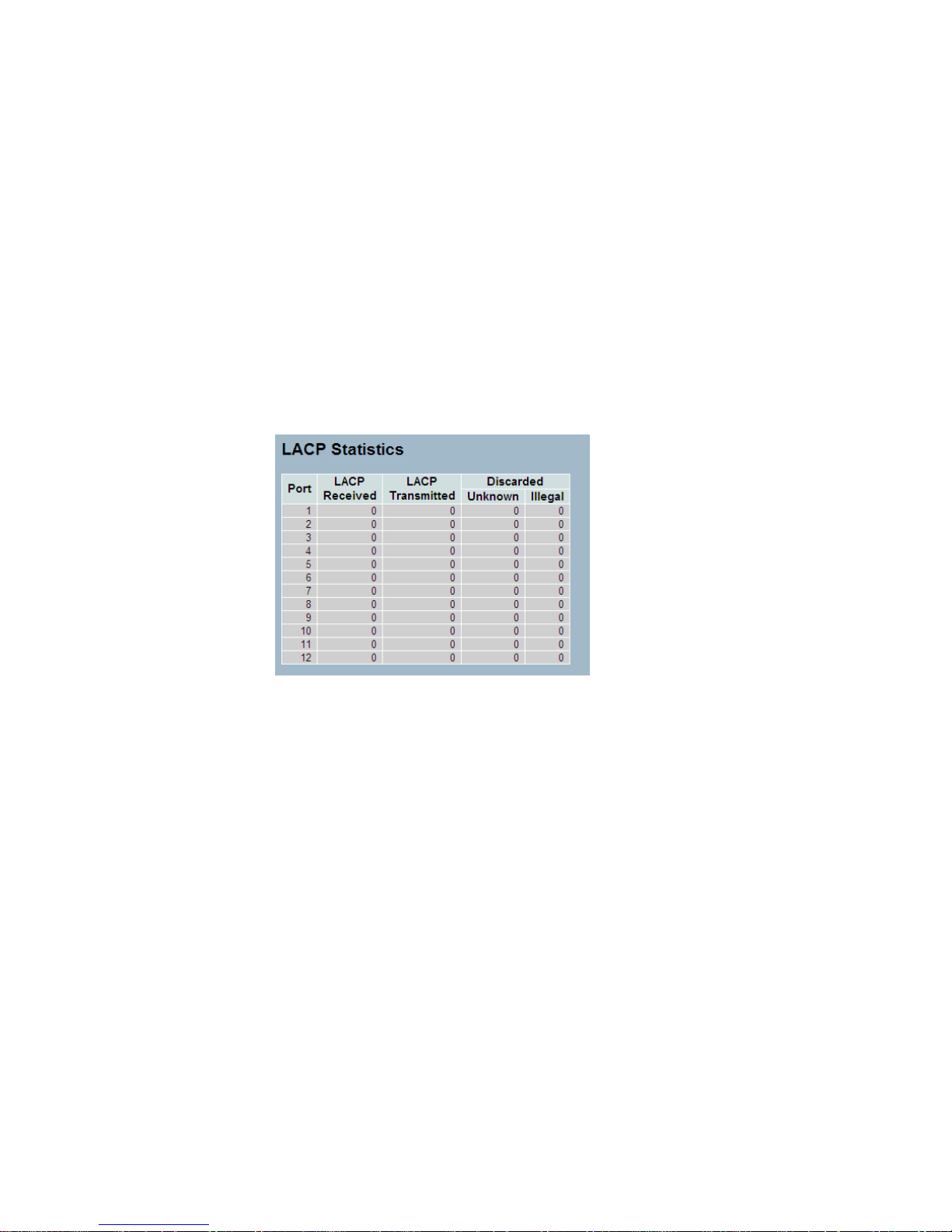
2-3.2.4 Port Statistics
This section describes that when you complete to set LACP function on the
switch then it provides a Port Statistics overview for all LACP instances
Web Interface
To display the LACP Port status in the web interface:
1. Click Configuration, LACP, Port Statistics
2. If you want to auto-refresh the information then you need to evoke the
―Auto refresh‖.
3. Click ― Refresh― to refresh the LACP Statistics.
Parameter description:
Port
The switch port number.
LACP Received
Shows how many LACP frames have been received at each port.
LACP Transmitted
Shows how many LACP frames have been sent from each port.
Discarded
Shows how many unknown or illegal LACP frames have been discarded at
each port.

2-4 Spanning Tree
The Spanning Tree Protocol (STP) can be used to detect and disable
network loops, and to provide backup links between switches, bridges or
routers. This allows the switch to interact with other bridging devices (that is,
an STP-compliant switch, bridge or router) in your network to ensure that
only one route exists between any two stations on the network, and provide
backup links which automatically take over when a primary link goes down.
STP - STP uses a distributed algorithm to select a bridging device (STPcompliant switch, bridge or router) that serves as the root of the spanning
tree network. It selects a root port on each bridging device (except for the
root device) which incurs the lowest path cost when forwarding a packet
from that device to the root device. Then it selects a designated bridging
device from each LAN which incurs the lowest path cost when forwarding a
packet from that LAN to the root device. All ports connected to designated
bridging devices are assigned as designated ports. After determining the
lowest cost spanning tree, it enables all root ports and designated ports,
and disables all other ports. Network packets are therefore only forwarded
between root ports and designated ports, eliminating any possible network
loops.
Once a stable network topology has been established, all bridges listen for
Hello BPDUs (Bridge Protocol Data Units) transmitted from the Root Bridge.
If a bridge does not get a Hello BPDU after a predefined interval (Maximum
Age), the bridge assumes that the link to the Root Bridge is down. This
bridge will then initiate negotiations with other bridges to reconfigure the
network to reestablish a valid network topology.
2-4.1 Bridge Settings
The section describes that how to configure the Spanning Tree Bridge and
STP System settings. It allows you to configure STP System settings are
used by all STP Bridge instance in the Swtich Stack.

Web Interface
To configure the Spanning Tree Bridge Settings parameters in the web
interface:
1. Click Configuration, Spanning Tree, Bridge Settings
2. Scoll to select the parameters and write down available value of
parameters in blank field in Basic Settings
3. Evoke to enable or disable the parameters and write down available
value of parameters in blank field in Advanced settings
4. Click the save to save the setting
5 .If you want to cancel the setting then you need to click the Reset button.
It will revert to previously saved values
Parameter description:
Basic Settings
Protocol Version
The STP protocol version setting. Valid values are STP, RSTP and MSTP.
Bridge Priority
Controls the bridge priority. Lower numeric values have better priority. The
bridge priority plus the MSTI instance number, concatenated with the 6-byte
MAC address of the switch forms a Bridge Identifier. For MSTP operation,
this is the priority of the CIST. Otherwise, this is the priority of the
STP/RSTP bridge.
Forward Delay
The delay used by STP Bridges to transit Root and Designated Ports to
Forwarding (used in STP compatible mode). Valid values are in the range 4
to 30 seconds.
Max Age
The maximum age of the information transmitted by the Bridge when it is
the Root Bridge. Valid values are in the range 6 to 40 seconds, and
MaxAge must be <= (FwdDelay-1)*2.

Maximum Hop Count
This defines the initial value of remaining Hops for MSTI information
generated at the boundary of an MSTI region. It defines how many bridges
a root bridge can distribute its BPDU information to. Valid values are in the
range 6 to 40 hops.
Transmit Hold Count
The number of BPDU's a bridge port can send per second. When exceeded,
transmission of the next BPDU will be delayed. Valid values are in the
range 1 to 10 BPDU's per second.
Advanced Settings
Edge Port BPDU Filtering
Control whether a port explicitly configured as Edge will transmit and
receive BPDUs.
Edge Port BPDU Guard
Control whether a port explicitly configured as Edge will disable itself upon
reception of a BPDU. The port will enter the error-disabled state, and will be
removed from the active topology.
Port Error Recovery
Control whether a port in the error-disabled state automatically will be
enabled after a certain time. If recovery is not enabled, ports have to be
disabled and re-enabled for normal STP operation. The condition is also
cleared by a system reboot.
Port Error Recovery Timeout
The time to pass before a port in the error-disabled state can be enabled.
Valid values are between 30 and 86400 seconds (24 hours).
2-4.2 MSTI Mapping
When you implement an Spanning Tree protocol on the switch that the
bridge instance. The CIST is not available for explicit mapping, as it will

receive the VLANs not explicitly mapped. Due to the reason that you need
to set the list of VLANs mapped to the MSTI. The VLANs must be
separated with comma and/or space. A VLAN can only be mapped to one
MSTI. An unused MSTI should just be left empty. (I.e. not having any
VLANs mapped to it.)
This section describes it allows the user to inspect the current STP MSTI
bridge instance priority configurations, and possibly change them as well.
Web Interface
To configure the Spanning Tree MSTI Mapping parameters in the web
interface:
1. Click Configuration, Spanning Tree, MSTI Mapping
2. Specify the configuration identification parameters in the field
Specify the VLANs Mapped blank field.
3. Click the save to save the setting
4. If you want to cancel the setting then you need to click the Reset button. It
will revert to previously saved values
Parameter description:
Configuration Identification
Configuration Name
The name identifying the VLAN to MSTI mapping. Bridges must share the
name and revision (see below), as well as the VLAN-to-MSTI mapping
configuration in order to share spanning trees for MSTI's (Intra-region). The
name is at most 32 characters.
Configuration Revision
The revision of the MSTI configuration named above. This must be an
integer between 0 and 65535.

MSTI Mapping
MSTI
The bridge instance. The CIST is not available for explicit mapping, as it will
receive the VLANs not explicitly mapped.
VLANs Mapped
The list of VLANs mapped to the MSTI. The VLANs must be separated with
comma and/or space. A VLAN can only be mapped to one MSTI. An
unused MSTI should just be left empty. (I.e. not having any VLANs

2-4.3 MSTI Poriorities
When you implement an Spanning Tree protocol on the switch that the
bridge instance. The CIST is the default instance which is always active.
For controls the bridge priority. Lower numeric values have better priority.
The bridge priority plus the MSTI instance number, concatenated with the 6byte MAC address of the switch forms a Bridege Identifier
The section describes it allows the user to inspect the current STP MSTI
bridge instance priority configurations, and possibly change them as well.
Web Interface
To configure the Spanning Tree MSTI Priorities parameters in the web
interface:
1. Click Configuration, Spanning Tree, MSTI Priorities
2. Scroll the Priority maximum is 240. Default is 128.
3. Click the save to save the setting
4. If you want to cancel the setting then you need to click the Reset button.
It will revert to previously saved values
Parameter description:
MSTI
The bridge instance. The CIST is the default instance, which is always
active.
Priority
Controls the bridge priority. Lower numeric values have better priority. The
bridge priority plus the MSTI instance number, concatenated with the 6-byte
MAC address of the switch forms a Bridge Identifier.

2-4.4 CIST Ports
When you implement an Spanning Tree protocol on the switch that the
bridge instance. You need to configure the CIST Ports. The section
describes it allows the user to inspect the to inspect the current STP CIST
port configurations, and possibly change them as well.
Web Interface
To configure the Spanning Tree CIST Ports parameters in the web interface:
1. Click Configuration, Spanning Tree, CIST Ports
2. Scroll and evoke to set all parameters of CIST Aggregated Port
Configuration.
3. Evoke to enable or disable the STP, then scoll and evoke to set all
parameters of the CIST normal Port configuration.
4. Click the save to save the setting
5. If you want to cancel the setting then you need to click the Reset button.
It will revert to previously saved values
Parameter description:
Port
The switch port number of the logical STP port.
STP Enabled
Controls whether STP is enabled on this switch port.
Path Cost
Controls the path cost incurred by the port. The Auto setting will set the path
cost as appropriate by the physical link speed, using the 802.1D
recommended values. Using the Specific setting, a user-defined value can
be entered. The path cost is used when establishing the active topology of
the network. Lower path cost ports are chosen as forwarding ports in favour
of higher path cost ports. Valid values are in the range 1 to 200000000.
Priority
Controls the port priority. This can be used to control priority of ports having
identical port cost. (See above).

operEdge (state flag)
Operational flag describing whether the port is connecting directly to edge
devices. (No Bridges attached). Transition to the forwarding state is faster
for edge ports (having operEdge true) than for other ports.The value of this
flag is based on AdminEdge and AutoEdge fields. This flag is displayed as
Edge in Monitor->Spanning Tree -> STP Detailed Bridge Status.
AdminEdge
Controls whether the operEdge flag should start as set or cleared. (The
initial operEdge state when a port is initialized).
AutoEdge
Controls whether the bridge should enable automatic edge detection on the
bridge port. This allows operEdge to be derived from whether BPDU's are
received on the port or not.
Restricted Role
If enabled, causes the port not to be selected as Root Port for the CIST or
any MSTI, even if it has the best spanning tree priority vector. Such a port
will be selected as an Alternate Port after the Root Port has been selected.
If set, it can cause lack of spanning tree connectivity. It can be set by a
network administrator to prevent bridges external to a core region of the
network influence the spanning tree active topology, possibly because
those bridges are not under the full control of the administrator. This feature
is also known as Root Guard.
Restricted TCN
If enabled, causes the port not to propagate received topology change
notifications and topology changes to other ports. If set it can cause
temporary loss of connectivity after changes in a spanning tree's active
topology as a result of persistently incorrect learned station location
information. It is set by a network administrator to prevent bridges external
to a core region of the network, causing address flushing in that region,
possibly because those bridges are not under the full control of the
administrator or the physical link state of the attached LANs transits
frequently.
BPDU Guard
If enabled, causes the port to disable itself upon receiving valid BPDU's.
Contrary to the similar bridge setting, the port Edge status does not effect
this setting.
A port entering error-disabled state due to this setting is subject to the
bridge Port Error Recovery setting as well.
Point2Point
Controls whether the port connects to a point-to-point LAN rather than to a
shared medium. This can be automatically determined, or forced either true
or false. Transition to the forwarding state is faster for point-to-point LANs
than for shared media.

2-4.5 MSTI Ports
The section describes it allows the user to inspect the current STP MSTI
port configurations, and possibly change them as well.
An MSTI port is a virtual port, which is instantiated separately for each
active CIST (physical) port for each MSTI instance configured on and
applicable to the port. The MSTI instance must be selected before
displaying actual MSTI port configuration options. It contains MSTI port
settings for physical and aggregated ports. The aggregation settings are
stack global.
Web Interface
To configure the Spanning Tree MSTI Port Configuration parameters in the
web interface:
1. Click Configuration, Spanning Tree, MSTI Ports
2. Scroll to select the MST1 or other MSTI Port
3. Click Get to set the detail parameters of the MSTI Ports.
4. Scroll to set all parameters of the MSTI Port configuration.
5. Click the save to save the setting
6. If you want to cancel the setting then you need to click the Reset button.
It will revert to previously saved values

Parameter description:
Port
The switch port number of the corresponding STP CIST (and MSTI) port.
Path Cost
Controls the path cost incurred by the port. The Auto setting will set the path
cost as appropriate by the physical link speed, using the 802.1D
recommended values. Using the Specific setting, a user-defined value can
be entered. The path cost is used when establishing the active topology of
the network. Lower path cost ports are chosen as forwarding ports in favour
of higher path cost ports. Valid values are in the range 1 to 200000000.
Priority
Controls the port priority. This can be used to control priority of ports having
identical port cost. (See above).

2-4.6 Bridge Status
After you complete the MSTI Port configuration the you could to ask the
switch display the Bridge Status. The Section provides a status overview of
all STP bridge instances. The displayed table contains a row for each STP
bridge instance, where the column displays the following information:
Web Interface
To display the STP Bridges status in the web interface:
1. Click Configuration, Spanning Tree, STP Bridges
2. If you want to auto-refresh the information then you need to evoke the
―Auto-refresh‖.
3. Click ― Refresh― to refresh the STP Bridges.
Parameter description:
MSTI
The Bridge Instance. This is also a link to the STP Detailed Bridge Status.
Bridge ID
The Bridge ID of this Bridge instance.
Root ID
The Bridge ID of the currently elected root bridge.
Root Port
The switch port currently assigned the root port role.
Root Cost
Root Path Cost. For the Root Bridge it is zero. For all other Bridges, it is the
sum of the Port Path Costs on the least cost path to the Root Bridge.
Topology Flag
The current state of the Topology Change Flag of this Bridge instance.
Topology Change Last
The time since last Topology Change occurred.

2-4.7 Port Status
After you complete the STP configuration the you could to ask the switch
display the STP Port Status. The Section provides you to ask switch to
display the STP CIST port status for physical ports of the currently selected
switch.:
Web Interface
To display the STP Port status in the web interface:
1. Click Configuration, Spanning Tree, STP Port Status
2. If you want to auto-refresh the information then you need to evoke the
―Auto-refresh‖.
3. Click ― Refresh― to refresh the STP Bridges.
Parameter description:
Port
The switch port number of the logical STP port.
CIST Role
The current STP port role of the CIST port. The port role can be one of the
following values: AlternatePort BackupPort RootPort DesignatedPort
Disabled.
CIST State
The current STP port state of the CIST port. The port state can be one of
the following values: Blocking Learning Forwarding.
Uptime
The time since the bridge port was last initialized.

2-4.8 Port Statistics
After you complete the STP configuration then you could to let the switch
display the STP Statistics. The Section provides you to ask switch to display
the STP Statistics detail counters of bridge ports in the currently selected
switch.
Web Interface
To display the STP Port status in the web interface:
1. Click Configuration, Spanning Tree, Port Statistics
2. If you want to auto-refresh the information then you need to evoke the
―Auto-refresh‖.
3. Click ― Refresh― to refresh the STP Bridges.
Parameter description:
Port
The switch port number of the logical STP port.
MSTP
The number of MSTP Configuration BPDU's received/transmitted on
the port.
RSTP
The number of RSTP Configuration BPDU's received/transmitted on the
port.
STP
The number of legacy STP Configuration BPDU's received/transmitted on
the port.
TCN
The number of (legacy) Topology Change Notification BPDU's
received/transmitted on the port.
Discarded Unknown
The number of unknown Spanning Tree BPDU's received (and discarded)
on the port.
Discarded Illegal
The number of illegal Spanning Tree BPDU's received (and discarded) on
the port.

2-5 IGMP Snooping
The function, is used to establish the multicast groups to forward the
multicast packet to the member ports, and, in nature, avoids wasting the
bandwidth while IP multicast packets are running over the network. This is
because a switch that does not support IGMP or IGMP Snooping can not
tell the multicast packet from the broadcast packet, so it can only treat them
all as the broadcast packet. Without IGMP Snooping, the multicast packet
forwarding function is plain and nothing is different from broadcast packet.
A switch supported IGMP Snooping with the functions of query, report and
leave, a type of packet exchanged between IP Multicast Router/Switch and
IP Multicast Host, can update the information of the Multicast table when a
member (port) joins or leaves an IP Multicast Destination Address. With this
function, once a switch receives an IP multicast packet, it will forward the
packet to the members who joined in a specified IP multicast group before.
The packets will be discarded by the IGMP Snooping if the user transmits
multicast packets to the multicast group that had not been built up in
advance. IGMP mode enables the switch to issue IGMP function that you
enable IGMP proxy or snooping on the switch, which connects to a router
closer to the root of the tree. This interface is the upstream interface. The
router on the upstream interface should be running IGMP.
2-5.1 Basic Configuration
The section describes how to set the basic IGMP snooping on the switch,
which connects to a router closer to the root of the tree. This interface is the
upstream interface. The router on the upstream interface should be running
IGMP.
Web Interface
To configure the IGMP Snooping parameters in the web interface:
1. Click Configuration, IGMP Snooping, Basic Configuration
2. Evoke to select enable or disable which Global configuration
3. Evoke which port wants to become a Router Port or enable/ disable the
Fast Leave function..
4. Scroll to set the Throtting parameter.
5. Click the save to save the setting
6. If you want to cancel the setting then you need to click the Reset button.
It will revert to previously saved values
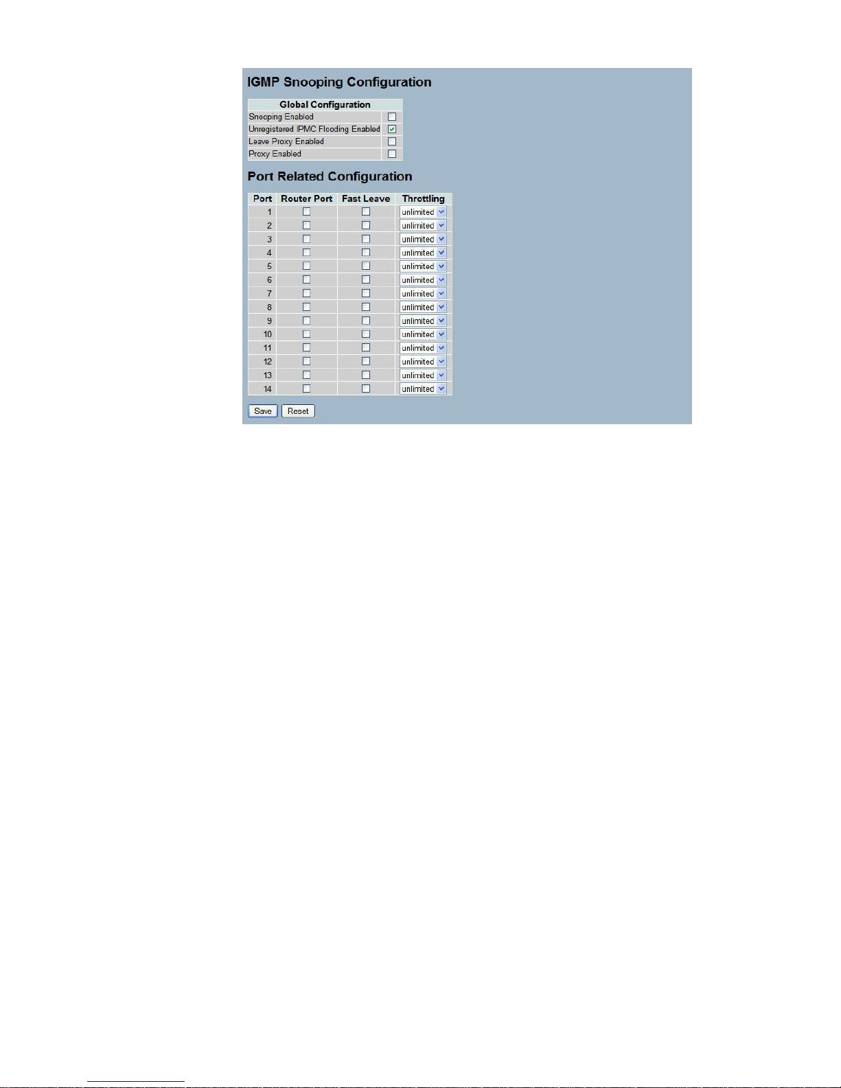
Parameter description:
Snooping Enabled
Enable the Global IGMP Snooping.
Unregistered IPMC Flooding enabled
Enable unregistered IPMC traffic flooding.
Leave Proxy Enabled
Enable IGMP Leave Proxy. This feature can be used to avoid forwarding
unnecessary leave messages to the router side.
Proxy Enabled
Enable IGMP Proxy. This feature can be used to avoid forwarding
unnecessary join and leave messages to the router side.
Router Port
Specify which ports act as router ports. A router port is a port on the
Ethernet switch that leads towards the Layer 3 multicast device or IGMP
querier.
If an aggregation member port is selected as a router port, the whole
aggregation will act as a router port.
Fast Leave
Enable the fast leave on the port.
Throttling
Enable to limit the number of multicast groups to which a switch port can
belong.

2-5.2 VLAN Configuration
The section describes the VLAN configuration setting process integrated
with IGMP Snooping function. For Each setting page shows up to 99 entries
from the VLAN table, default being 20, selected through the "entries per
page" input field. When first visited, the web page will show the first 20
entries from the beginning of the VLAN Table. The first displayed will be the
one with the lowest VLAN ID found in the VLAN Table. The "VLAN" input
fields allow the user to select the starting point in the VLAN Table. Clicking
the button will update the displayed table starting from that or the next
closest VLAN Table match.
Web Interface
To configure the IGMP Snooping VLAN Configuration in the web interface:
1. Click Configuration, IGMP Snooping, VLAN Configuration
2. Evoke to select enable or disable Snooping , IGMP Querier
Specify the parameters in the blank field.
3. Click the refresh to update the data or click << or >> to display previous
entry or next entry.
4. Click the save to save the setting
5. If you want to cancel the setting then you need to click the Reset button.
It will revert to previously saved values
Parameter description:
Snooping Enabled
Enable the Global IGMP Snooping.
Unregistered IPMC Flooding enabled
Enable unregistered IPMC traffic flooding.
Leave Proxy Enabled
Enable IGMP Leave Proxy. This feature can be used to avoid forwarding
unnecessary leave messages to the router side.

Proxy Enabled
Enable IGMP Proxy. This feature can be used to avoid forwarding
unnecessary join and leave messages to the router side.
Router Port
Specify which ports act as router ports. A router port is a port on the
Ethernet switch that leads towards the Layer 3 multicast device or IGMP
querier.
If an aggregation member port is selected as a router port, the whole
aggregation will act as a router port.
Fast Leave
Enable the fast leave on the port.
Throttling
Enable to limit the number of multicast groups to which a switch port can
belong.
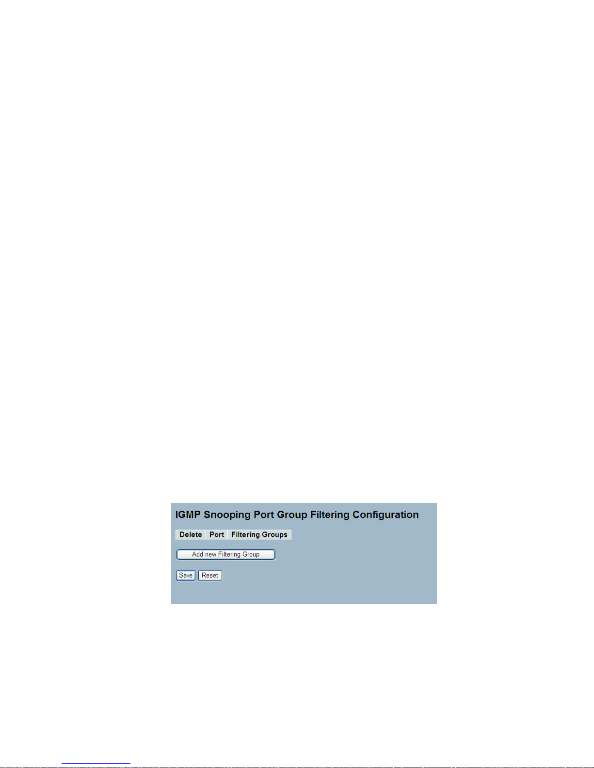
2-5.3 Port Group Fitering
The section describes how to set the IGMP Port Group Filtering? With the
IGMP filtering feature, an user can exert this type of control. In some
network Application environments, as like the metropolitan or multipledwelling unit (MDU) installations, an user might want to control the multicast
groups to which a user on a switch port can belong. It allows the user to
control the distribution of multicast services, such as IP/TV, based on some
type of subscription or service plan.
With this feature, you can filter multicast joins on a per-port basis by
configuring IP multicast profiles and associating them with individual switch
ports. An IGMP profile can contain one or more multicast groups and
specifies whether access to the group is permitted or denied. If an IGMP
profile denying access to a multicast group is applied to a switch port, the
IGMP join report requesting the stream of IP multicast traffic is dropped,
and the port is not allowed to receive IP multicast traffic from that group. If
the filtering action permits access to the multicast group, the IGMP report
from the port is forwarded for normal processing.
IGMP filtering controls only IGMP membership join reports and has no
relationship to the function that directs the forwarding of IP multicast traffic.
Web Interface
To configure the IGMP Snooping Port Group Configuration in the web
interface:
1. Click Configuration, IGMP Snooping, Port Group Filtering
2. Click Add new Filtering Group
3. Scroll the Port to enable the Port Group Filtering.
Specify the Filtering Groups in the blank field.
4. Click the save to save the setting
5. If you want to cancel the setting then you need to click the Reset button.
It will revert to previously saved values

Parameter description:
Delete
Check to delete the entry. It will be deleted during the next save.
Port
The logical port for the settings.
Filtering Groups
The IP Multicast Group that will be filtered.
Adding New Filtering Group
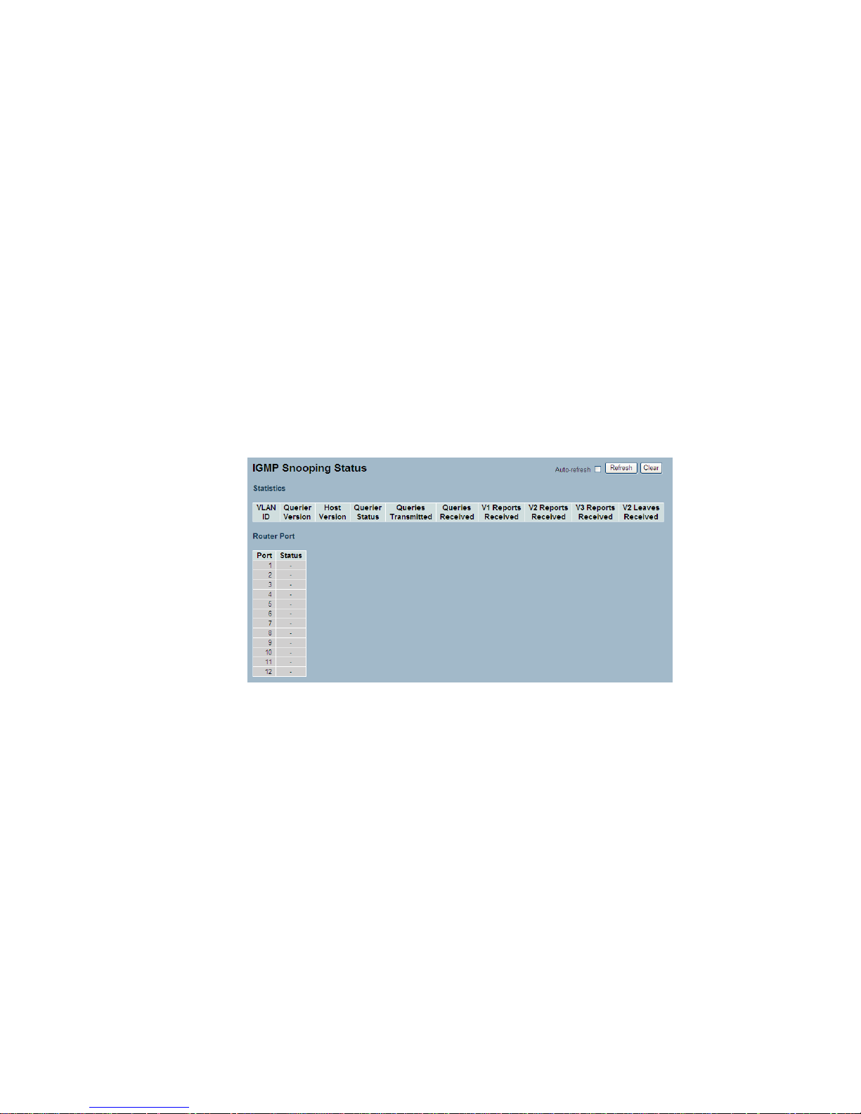
2-5.4 Status
After you complete the IGMP Snooping configuration, then you could to let
the switch display the IGMP Snooping Status. The Section provides you to
let switch to display the IGMP Snooping detail status.
Web Interface
To display the IGMP Snooping status in the web interface:
1. Click Configuration, IGMP Snooping, Status
2. If you want to auto-refresh the information then you need to evoke the
―Auto-refresh‖.
3. Click ― Refresh― to refresh the IGMP Snooping Status.
4. Click ― Clear― to clear the IGMP Snooping Status.
Parameter description:
VLAN ID
The VLAN ID of the entry.
Querier Version
Working Querier Version currently.
Host Version
Working Host Version currently.
Querier Status
Shows the Querier status is "ACTIVE" or "IDLE".
Queries Transmitted
The number of Transmitted Queries.
Queries Received

The number of Received Queries.
V1 Reports Received
The number of Received V1 Reports.
V2 Reports Received
The number of Received V2 Reports.
V3 Reports Received
The number of Received V3 Reports.
V2 Leaves Received
The number of Received V2 Leaves.

2-5.5 Group Infermation
After you complete to set the IGMP Snooping function then you could let
the switch to display the IGMP Snooping Group Information. Entries in the
IGMP Group Table are shown on this page. The IGMP Group Table is
sorted first by VLAN ID, and then by group. The will use the last entry of the
currently displayed table as a basis for the next lookup. When the end is
reached the text "No more entries" is shown in the displayed table. Use the
button to start over.
Web Interface
To display the IGMP Snooping Group Information in the web interface:
1. Click Configuration, IGMP Snooping, Group Information
2. If you want to auto-refresh the information then you need to evoke the
―Auto-refresh‖.
3. Click ― Refresh― to refresh a entry of the IGMP Snooping Groups
Information.
4. Click ―<< or >> ― to move to previous or next entry.
Parameter description:
Navigating the IGMP Group Table
The "Start from VLAN", and "group" input fields allow the user to select the
starting point in the IGMP Group Table. The will use the last entry of the
currently displayed table as a basis for the next lookup. When the end is
reached the text "No more entries" is shown in the displayed table.
IGMP Group Table Columns
VLAN ID
VLAN ID of the group.
Groups
Group address of the group displayed.
Port Members
Ports under this group.

2-5.6 IPv4 SSM information
Source Specific Multicast (SSM) is a datagram delivery model that best
supports one-to-many applications, also known as broadcast applications.
SSM is a core network technology of IP multicast targeted for audio and
video broadcast application environments.
For the SSM delivery mode, an IP multicast receiver host must use IGMP
Version 3 (IGMPv3) to subscribe to channel (S, G). By subscribing to this
channel, the receiver host is indicating that it wants to receive IP multicast
traffic sent by source host S to group G. The network will deliver IP multicast
packets from source host S to group G to all hosts in the network that have
subscribed to the channel (S, G).
SSM does not require group address allocation within the network, only
within each source host. Different applications running on the same source
host must use different SSM groups. Different applications running on
different source hosts can arbitrarily reuse SSM group addresses without
causing any excess traffic on the network.
Addresses in the range 232.0.0.0/8 (232.0.0.0 to 232.255.255.255) are
reserved for SSM by IANA. In the switch, you can configure SSM for
arbitrary IP multicast addresses also.
Web Interface
To display the IGMPv3 IPv4 SSM Information in the web interface:
1. Click Configuration, IGMP Snooping, IPv4 SSM Information
2. If you want to auto-refresh the information then you need to evoke the
―Auto-refresh‖.
3. Click ― Refresh― to refresh a entry of the IGMPv3 IPv4 SSM Information.
4. Click ―<< or >> ― to move to previous or next entry.
Parameter description:
Navigating the IGMPv3 Information Table
Each page shows up to 99 entries from the IGMPv3 SSM (Source Specific
Multicast) Information table, default being 20, selected through the "entries
per page" input field. When first visited, the web page will show the first 20
entries from the beginning of the IGMPv3 Information Table.
The "Start from VLAN", and "group" input fields allow the user to select the
starting point in the IGMPv3 Information Table. Clicking the button will
update the displayed table starting from that or the closest next IGMPv3
Information Table match. In addition, the two input fields will - upon a button

click - assume the value of the first displayed entry, allowing for continuous
refresh with the same start address.
The will use the last entry of the currently displayed table as a basis for the
next lookup. When the end is reached the text "No more entries" is shown
in the displayed table. Use the button to start over.
IGMPv3 Information Table Columns
VLAN ID
VLAN ID of the group.
Group
Group address of the group displayed.
Port
Switch port number.
Mode
Indicates the filtering mode maintained per (VLAN ID, port number, Group
Address) basis. It can be either Include or Exclude.
Source Address
IP Address of the source. Currently, system limits the total number of IP
source addresses for filtering to be 128.
Type
Indicates the Type. It can be either Allow or Deny.

2-6 MLD Snooping
Curiously enough, a network node that acts as a source of IPv6 multicast
traffic is only an indirect participant in MLD snooping—it just provides
multicast traffic, and MLD doesn’t interact with it. (Note, however, that in an
application like desktop conferencing a network node may act as both a
source and an MLD host; but MLD interacts with that node only in its role as
an MLD host.)
A source node creates multicast traffic by sending packets to a multicast
address. In IPv6, addresses with the first eight bits set (that is, ―FF‖ as the
first two characters of the address) are multicast addresses, and any node
that listens to such an address will receive the traffic sent to that address.
Application software running on the source and destination systems
cooperates to determine what multicast address to use. (Note that this is a
function of the application software, not of MLD.)
When MLD snooping is enabled on a VLAN, the switch acts to minimize
unnecessary multicast traffic. If the switch receives multicast traffic destined
for a given multicast address, it forwards that traffic only to ports on the
VLAN that have MLD hosts for that address. It drops that traffic for ports on
the VLAN that have no MLD hosts
2-6.1 Basic Configuration
The section will let you understand how to configure the MLD Snooping
basic configuration and the parameters .
 Loading...