

1
Lantech
LGS-2424C
24 10/100/1000T with 4 1000SFP shared
cage SNMP Managed Switch
User Manual
v1.30
Aug 2008
2
Release Note
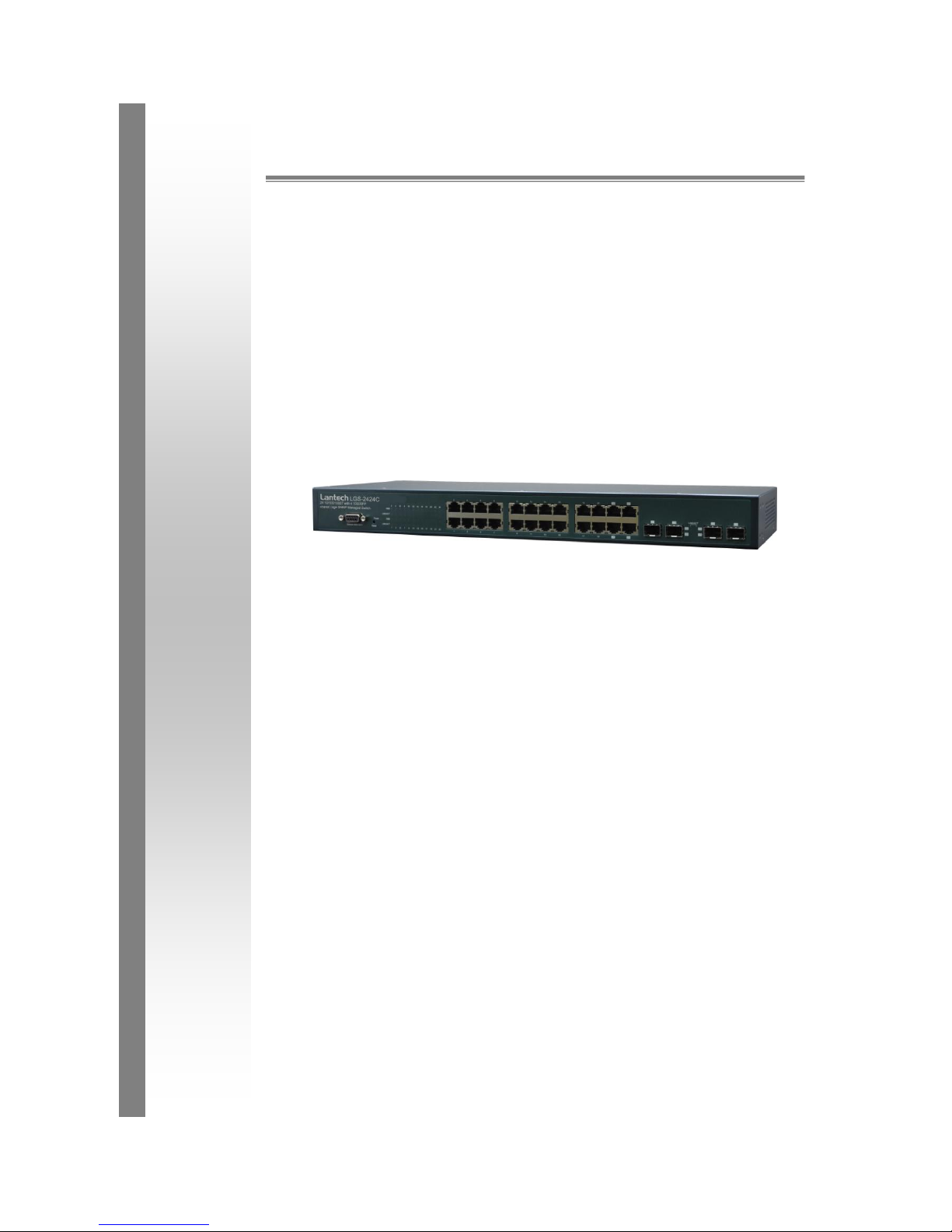
24 10/100/1000T with 4 1000SFP shared cage SNMP Managed Switch
Update
Current
Version
Progress status
PM
25/Dec/2006
V1.00
New edit
Anson
12/Feb/2007
V1.10
Update Firmware Release 1.10
Anson
12/Dec/2007
V1.20
Update Firmware version 1.05
Anson
04/Aug/2008
V1.30
Re-sort the items of content, update firmware
v1.06
E.C.

3
FCC Warning
This Equipment has been tested and found to comply with the limits for a Class A digital
device, pursuant to Part 15 of the FCC rules. These limits are designed to provide
reasonable protection against harmful interference in a residential installation. This
equipment generates uses and can radiate radio frequency energy and, if not installed
and used in accordance with the instructions, may cause harmful interference to radio
communications. However, there is no guarantee that interference will not occur in a
particular installation. If this equipment does cause harmful interference to radio or
television reception, which can be determined by turning the equipment off and on, the
user is encouraged to try to correct the interference by one or more of the following
measures:
Reorient or relocate the receiving antenna.
Increase the separation between the equipment and receiver.
Connect the equipment into an outlet on a circuit different from that to which the
receiver is connected.
Consult the dealer or an experienced radio/TV technician for help.
CE Mark Warning
This is a Class-A product. In a domestic environment this product may cause radio
interference in which case the user may be required to take adequate measures.

4
Content
Chapter 1 Introduction .......................................................................................................... 7
1.1 Hardware Features ..................................................................................................... 7
1.2 Software Feature ........................................................................................................ 9
1.3 Package Contents ................................ .................................................................... 10
Chapter 2 Hardware Description ........................................................................................ 11
2.1 Physical Dimension .................................................................................................. 11
2.2 Front Panel ............................................................................................................... 11
2.3 Rear Panel................................................................................................................ 12
2.4 LED Indicators .......................................................................................................... 12
Chapter 3 Hardware Installation ......................................................................................... 14
3.1 Desktop Installation .................................................................................................. 14
3.2 Rack-mounted Installation ........................................................................................ 14
3.3 Cabling ..................................................................................................................... 15
Chapter 4 Network Application .......................................................................................... 17
4.1 Desktop Application .................................................................................................. 17
4.2 Segment Application ................................................................................................. 17
Chapter 5 Console Management ........................................................................................ 19
5.1 Connecting to the Console Port ................................................................................ 19
5.2 Login in the Console Interface .................................................................................. 19
5.3 CLI Management ...................................................................................................... 21
5.4 Commands Level: ..................................................................................................... 21
Chapter 6 Web-Based Management ................................................................................... 23
6.1 About Web-based Management ............................................................................... 23
6.2 Preparing for Web Management ............................................................................... 23
6.3 System Login ............................................................................................................ 23
6.4 System Configuration ............................................................................................... 24
6.5 Console Info ............................................................................................................. 25
6.6 Port Statistics ............................................................................................................ 25
6.7 Port Configuration ..................................................................................................... 26
6.8 Port Trunk Configuration .......................................................................................... 28
6.9 Port Mirroring ............................................................................................................ 29
6.10 VLAN Setting .......................................................................................................... 29
6.10.1 VLAN Port Setting ........................................................................................ 30

5
6.11 LACP Setting .......................................................................................................... 31
6.11.1 LACP Status ................................................................................................. 33
6.12 RSTP Configuration ................................................................................................ 35
6.12.1 RSTP Configuration Tab .............................................................................. 35
6.12.2 RSTP Port Configuration .............................................................................. 36
6.12.3 RSTP Status Tab ......................................................................................... 36
6.13 SNMP Setting ......................................................................................................... 38
6.14 QoS Configuration .................................................................................................. 40
6.14.1 QoS DSCP Mapping..................................................................................... 41
6.14.2 Priority Queue Service .................................................................................. 42
6.14.3 QoS Vlan Tag ............................................................................................... 43
6.15 IGMP Configuration ................................................................................................ 44
6.15.1 IGMP Status ................................................................................................. 45
6.16 Rate Limit Configuration ......................................................................................... 46
6.17 Security Configuration ............................................................................................ 47
6.18 802.1X Configuration .............................................................................................. 48
6.18.1 802.1X Parameters ...................................................................................... 50
6.18.2 802.1X Statistics ........................................................................................... 51
6.19 MAC Address Table Control ................................ ................................ ................... 52
6.19.1 Static MAC Address Entries in Permanent Table ......................................... 53
6.20 TFTP Firmware Upload .......................................................................................... 54
6.20.1 TFTP Firmware Backup ................................................................................ 55
6.20.2 TFTP Configuration Restore ......................................................................... 55
6.20.3 TFTP Configuration Backup ......................................................................... 56
6.21 Software Upload ..................................................................................................... 56
6.21.1 Configuration Upload/Download ................................................................... 57
6.22 Factory Default ....................................................................................................... 58
6.23 Warm Restart ......................................................................................................... 58
6.24 Logout .................................................................................................................... 58
Troubleshooting .................................................................................................................. 59
Appendix A- Command Sets .............................................................................................. 61
System Commands ........................................................................................................ 61
Console Commands ....................................................................................................... 62
Port Commands.............................................................................................................. 63

6
MAC Commands ............................................................................................................ 65
VLAN Commands ........................................................................................................... 67
Aggr Commands ............................................................................................................. 69
LACP Commands ........................................................................................................... 69
RSTP Commands ........................................................................................................... 70
QoS Commands ................................ ............................................................................. 72
Mirror Commands ........................................................................................................... 74
IP Commands ................................................................................................................. 75
802.1x Commands ......................................................................................................... 76
Filter Commands ............................................................................................................ 78
IGMP Commands ........................................................................................................... 79

7
Chapter 1 Introduction
The 24 10/100/1000T with 4 1000SFP shared cage SNMP Managed Switch is a
multi-port switch that can be used to build high-performance switched workgroup
networks. It provides wire-speed, Fast Ethernet switching function that allows
high-performance, low-cost connection. The Switch features a store-and-forward
switching and it can auto-learn and store source address on an 8K-entry MAC address
table.
The 24 10/100/1000T with 4 1000SFP shared cage SNMP Managed Switch has 20
auto-sensing 10/100/1000Base-TX RJ-45 ports and 4 Mini-GBIC ports for higher
connection speed.
1.1 Hardware Features
Standards
IEEE802.3 10Base-T Ethernet
IEEE802.3u 100Base-TX
IEEE802.3ab 1000Base-T
IEEE802.3z Gigabit fiber
IEEE802.3x Flow Control and Back Pressure
IEEE802.3ad Port trunk with LACP
IEEE802.1d Spanning Tree/ IEEE802.1w Rapid
Spanning Tree
IEEE802.1p Class of Service
IEEE802.1Q VLAN Tag
IEEE802.1x User Authentication (Radius)
Switch architecture
Back-plane (Switching Fabric): 48Gbps
Packet throughput ability (Full-Duplex): 71.42Mpps
@64bytes

8
Transfer Rate
14,880pps for Ethernet port
148,800pps for Fast Ethernet port
1,488,000pps for Gigabit Ethernet port
Packet buffer
500Kbytes
Jumbo Packet
9600bytes
MAC Address
8K
Flash ROM
512Kbytes x 2
SRAM
128Kbytes
Connector
1000Base-T: 24 x RJ-45 with auto MDI/MDI-X
Gigabit fiber: 4 x MINI-GBIC socket; shared with last
4-port RJ-45
Protocol
CSMA/CD
LED
System Power (Green)
Gigabit Copper port: Link/Activity(Green),
100/1000Mbps (Green)
Mini GBIC: Link/Activity (Green)
Power Supply
AC 100 ~ 240V, 50/60Hz, 1A (Max)
Power Consumption
17.9 Watts (open issue)
Operating Humidity
10% ~ 90% (Non-condensing)
Operating Temp.
0oC ~ 45oC
Storage Temp.
-40oC ~ 70oC
Case Dimension
440mm (W) x 161mm (D) x 44mm (H)
Ventilation
1 Fan for ventilating
Installation
19” EIA/TIA Rack design

9
EMI
Compliance with FCC Class A, CE
Safety
Compliance with UL, cUL, CE/EN60950-1
1.2 Software Feature
Management
SNMP v1, Telnet, CLI, Web management
SNMP MIB
RFC 1213 MIBII,
RFC 1493 Bridge MIB
VLAN
Port based VLAN
IEEE802.1Q Tag VLAN(256 entries)/VLAN ID (VLAN
ID can be assigned from 1 to 4094)
Port Trunk
8 Trunk groups
LACP
24 trunk members
Spanning Tree
IEEE802.1d Spanning tree
IEEE802.1w Rapid spanning tree
Quality of service
The quality of service determined by port, Tag and
IPv4 Type of Service, IPv4 Different Service
Class of Service
Supports IEEE 802.1p class of service, per port
provides 4 priority queues
Port Mirror
TX and RX packet
IGMP
Supports IGMP snooping v1, v2
200 multicast groups
IP Security
Supports 1 IP address that has permission to access
the switch management and to prevent unauthorized
intruder

10
Login Security
Supports IEEE 802.1x Authentication/RADIUS
Bandwidth Control
The rate control supports all of packet type and the
limit rates are 128K~3968Kbps
Flow Control
Supports Flow Control for Full-duplex and Back
Pressure for Half-duplex
SNMP Trap
Up to 1 Trap station,
Cold start,
Port link up, Port link down
DHCP
DHCP Client
Firmware Upgrade
Supports Web interface for firmware upgrade,
backup, and restore
1.3 Package Contents
Unpack the contents of the 24 10/100/1000T with 4 1000SFP shared cage SNMP
Managed Switch and verify them against the checklist below.
24 10/100/1000T with 4 1000SFP shared cage SNMP Managed Switch
Four Rubber Feet
Power Cord
RS-232 cable
User Manual
Compare the contents of the 24 10/100/1000T with 4 1000SFP shared cage SNMP
Managed Switch package with the standard checklist above. If any item is missing or
damaged, please contact your local dealer for service.
11
Chapter 2 Hardware Description
This section mainly describes the hardware of the 24 10/100/1000T with 4 1000SFP
shared cage SNMP Managed Switch.
2.1 Physical Dimension
The physical dimensions of the 24 10/100/1000T with 4 1000SFP shared cage SNMP
Managed Switch is 440mm(W) x 161mm(D) x 44mm(H)
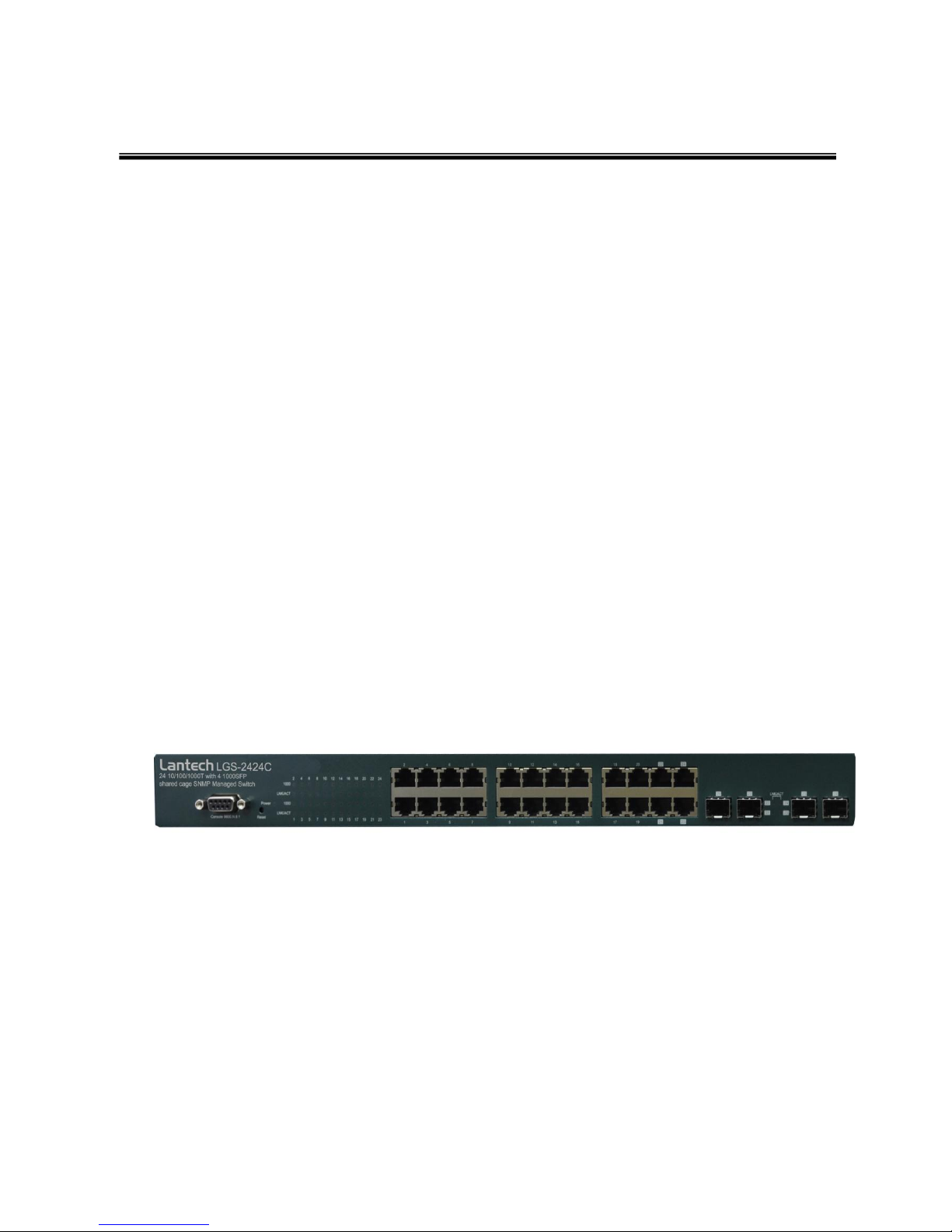
2.2 Front Panel
The Front Panel of the 24 10/100/1000T with 4 1000SFP shared cage SNMP Managed
Switch consist of 24 x auto-sensing 10/100/1000Mbps Ethernet RJ-45 ports (automatic
MDI/MDIX), 4 Mini GBIC ports, and the LED indicators are also located on the front
panel of the switch.
Front Panel of the 24 10/100/1000T with 4 1000SFP shared cage SNMP Managed Switch
RJ-45 Ports (Auto MDI/MDIX): 24 10/100/1000 auto-sensing for 10Base-T or
100Base-TX or 1000Base-T connections.
In general, MDI means connecting to another Hub or Switch while MDIX means
connecting to a workstation or PC. Therefore, Auto MDI/MDIX means that you can
connect to another Switch or workstation without changing non-crossover or
crossover cabling.
12
4 Mini-GBIC ports: The appropriate replaceable Mini-GBIC ports are available with
a variety of different transmitter and receiver types, allowing users to select the
appropriate transceiver for each link to provide the required optical reach over
the available optical fiber type. Ports 21 ~ 24 are the four combo ports which
consist of one RJ-45 port and one mini-GBIC port each. Traditional RJ-45 ports
can be used for uplinking wide-band paths in short distance (<100m), or the
appropriate replaceable mini-GBIC ports can be used for the application of
wide-band uplinking and long distance transmissions to fit the flexible field request.
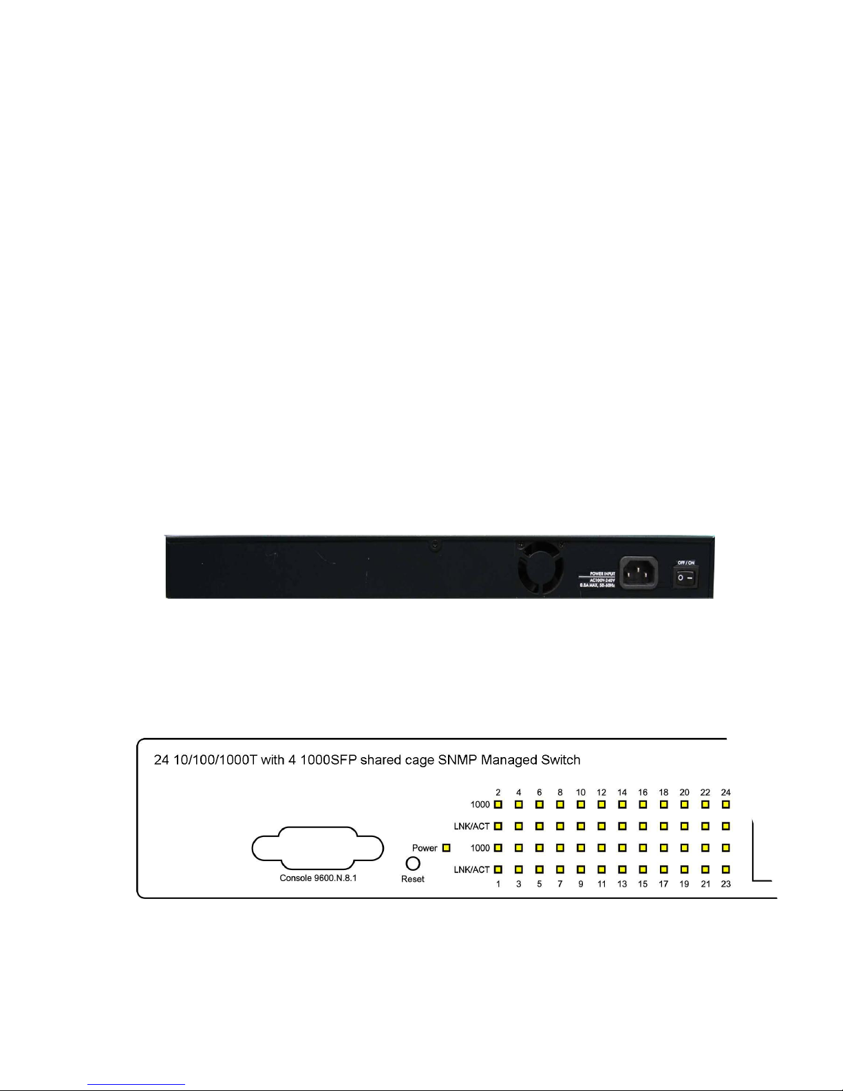
2.3 Rear Panel
The 3-pronged power plug is located at the Rear Panel of 24 10/100/1000T with 4
1000SFP shared cage SNMP Managed Switch as shown in the figure below. The Switch
will work with AC in the range of 100-240V AC, 50-60Hz.
Rear Panel of the 24 10/100/1000T with 4 1000SFP shared cage SNMP Managed Switch
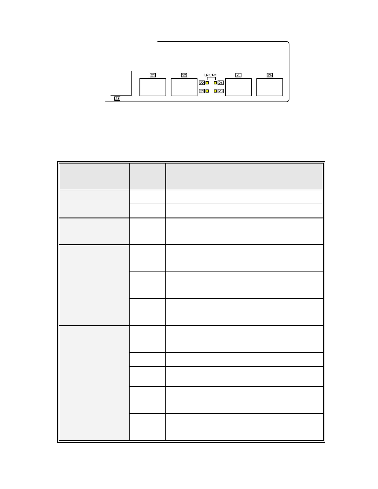
2.4 LED Indicators
13
LED Indicators
The following table provides descriptions of the LED statuses and meaning. They
provide a real-time indication of systematic operation status.
LED
Status
Description
Power
Green
Power On
Off
No power input
1000
Green
The port is operating at the speed of
1000Mbps.
LNK / ACT
Green
The port is successfully connecting with the
device.
Blinks
The port is receiving or transmitting data.
Off
No device attached.
LNK / ACT
(MINI GBIC)
Green
The port is successfully connecting with the
device.
Blinks
The port is receiving or transmitting data.
Off
No device attached.
Blinks
Collision packet detection
Off
No device attached.

14
Chapter 3 Hardware Installation
3.1 Desktop Installation
Set the switch on a sufficiently large flat space with a power outlet nearby. The surface
where you put your Switch should be clean, smooth, level, and sturdy. Make sure there
is enough clearance around the Switch to allow attachment of cables, power cord and air
circulation.
Attaching Rubber Feet
1. Make sure mounting surface on the bottom of the Switch is grease and dust free.
2. Remove adhesive backing from your Rubber Feet.
3. Apply the Rubber Feet to each corner on the bottom of the Switch. These footpads
can prevent the Switch from shock/vibration.
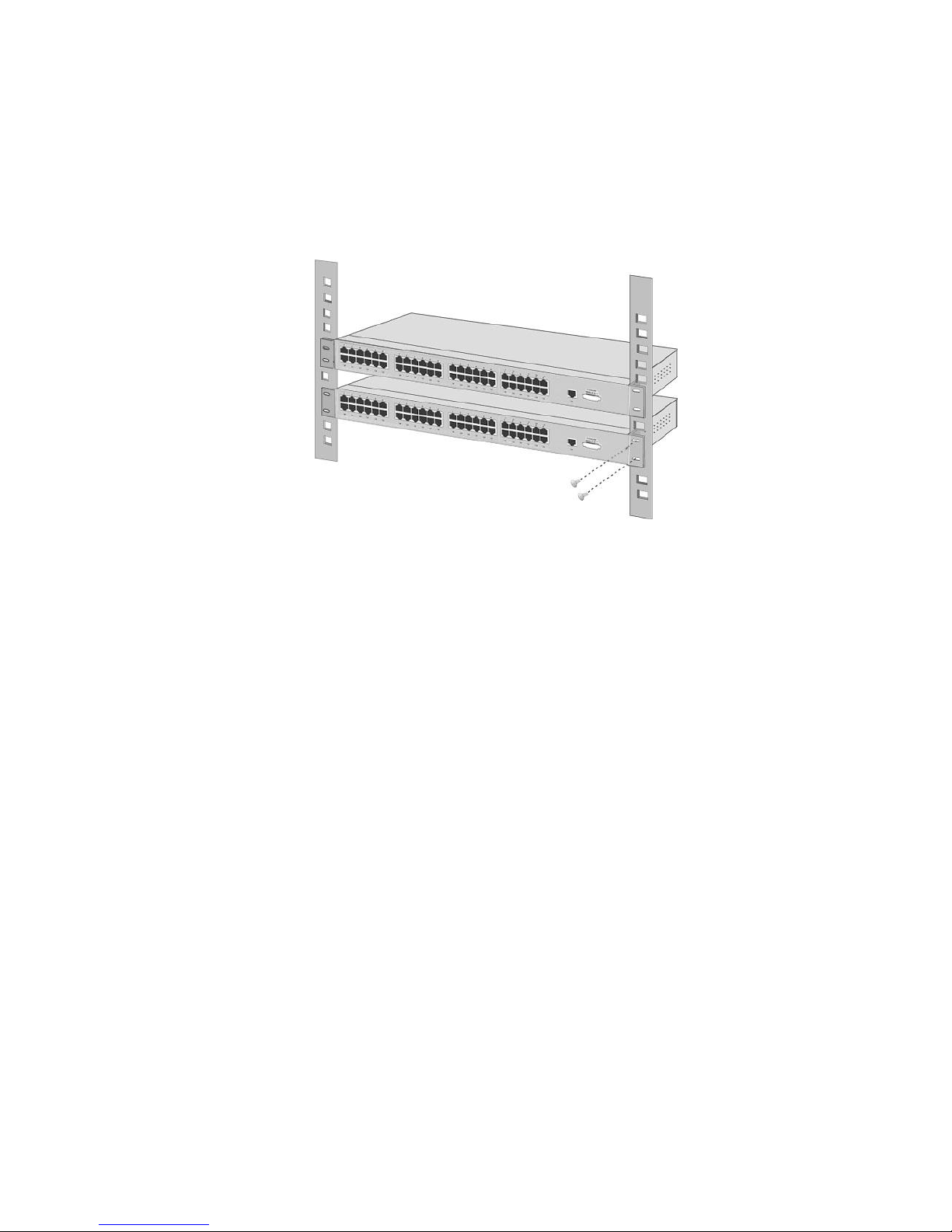
3.2 Rack-mounted Installation
The Switch comes with a rack-mounted kit and can be mounted in an EIA standard size,
19-inch Rack. It can be placed in a wiring closet with other equipment.
Perform the following steps to rack-mount the switch:
A. Position one plate to align with the holes on one side of the hub and secure it with
the smaller plate screws. Then, attach the remaining plate to the other side of the
Switch.
Attach mounting plates with screws
15
B. After attaching both mounting plates, position the Switch in the rack by lining up the
holes in the plates with the appropriate holes on the rack. Secure the Switch to the
rack with a screwdriver and the rack-mounting screws.
Mount the Switch in an EIA standard 19-inch Rack
Note: For proper ventilation, allows about at least 4 inches (10 cm) of clearance on the
front and 3.4 inches (8 cm) on the back of the Switch. This is especially important for
enclosed rack installation.
3.3 Cabling
Use four twisted-pair, Category 5e or above cabling for RJ-45 port connection. The
cable between the switch and the link partner (switch, hub, workstation, etc.) must
be less than 100 meters (328 ft.) long.
Fiber segment using single-mode connector can be applied to standard (such as
9/125 µm, 9.5/125 µm, or 10/125 µm) single-mode fiber cable. User can connect two
devices in the distance up to 30km.
Fiber segment using multi-mode connector can be applied to standard (such as 50
or 62.5/125 µm) multi-mode fiber cable. User can connect two devices up to 2km
distances.
16
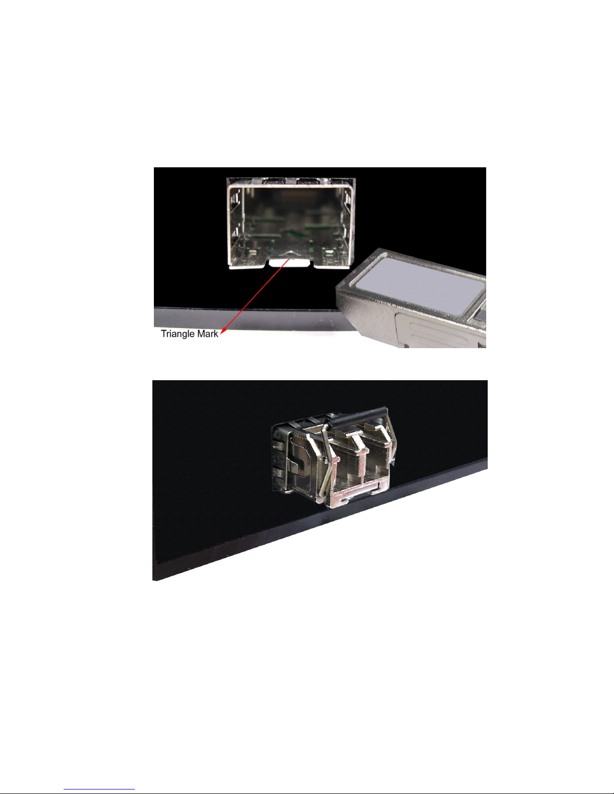
To connect the transceiver and LC cable, please follow the steps shown below:
First, insert the transceiver into the SFP module. Notice that the triangle mark is the
bottom of the module.
Transceiver to the SFP module
Transceiver Inserted
Second, insert the fiber cable of LC connector into the transceiver.
17
Chapter 4 Network Application
This section provides you a few samples of network topology in which the switch is used.
In general, the 24 10/100/1000T with 4 1000SFP shared cage SNMP Managed Switch is
designed to be used as a desktop or segment switch.
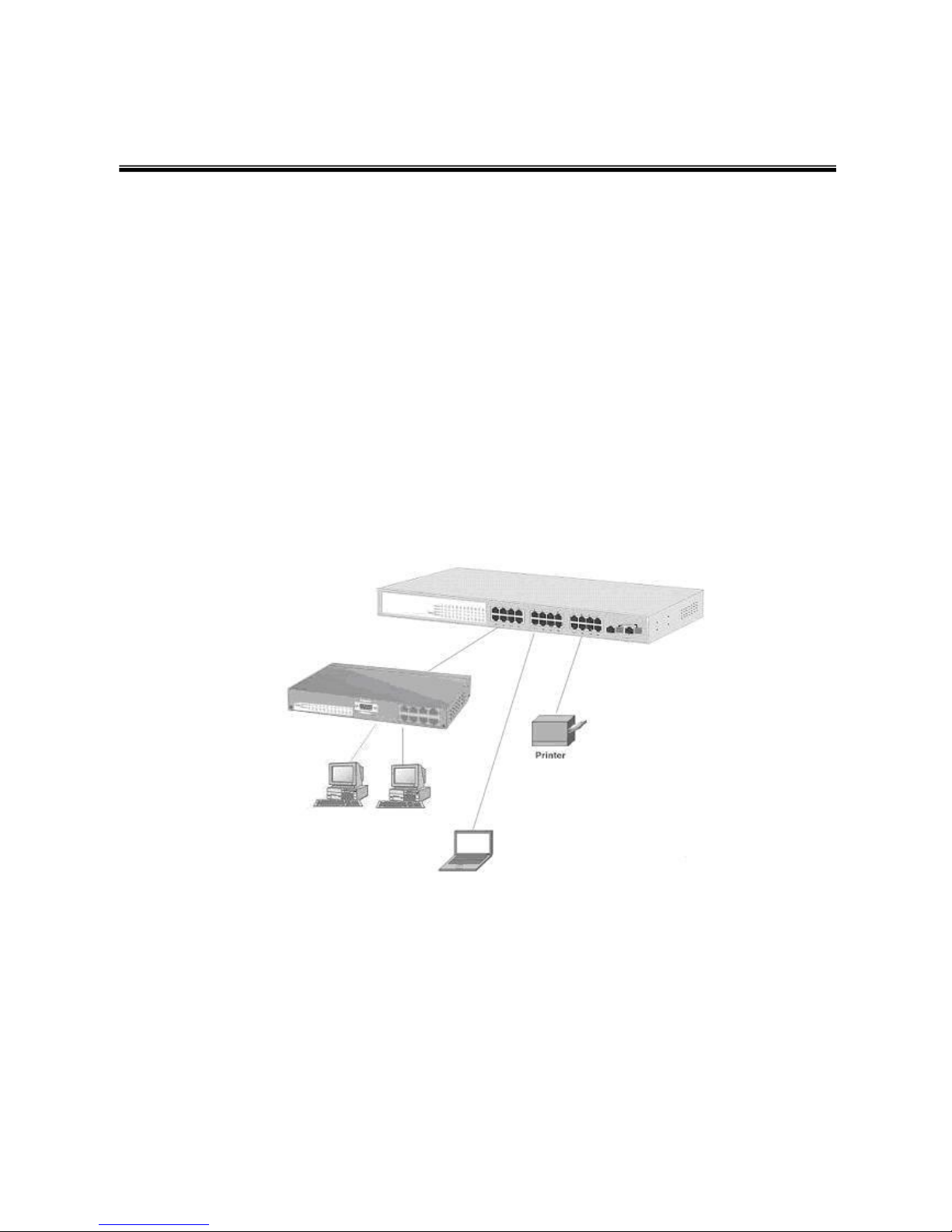
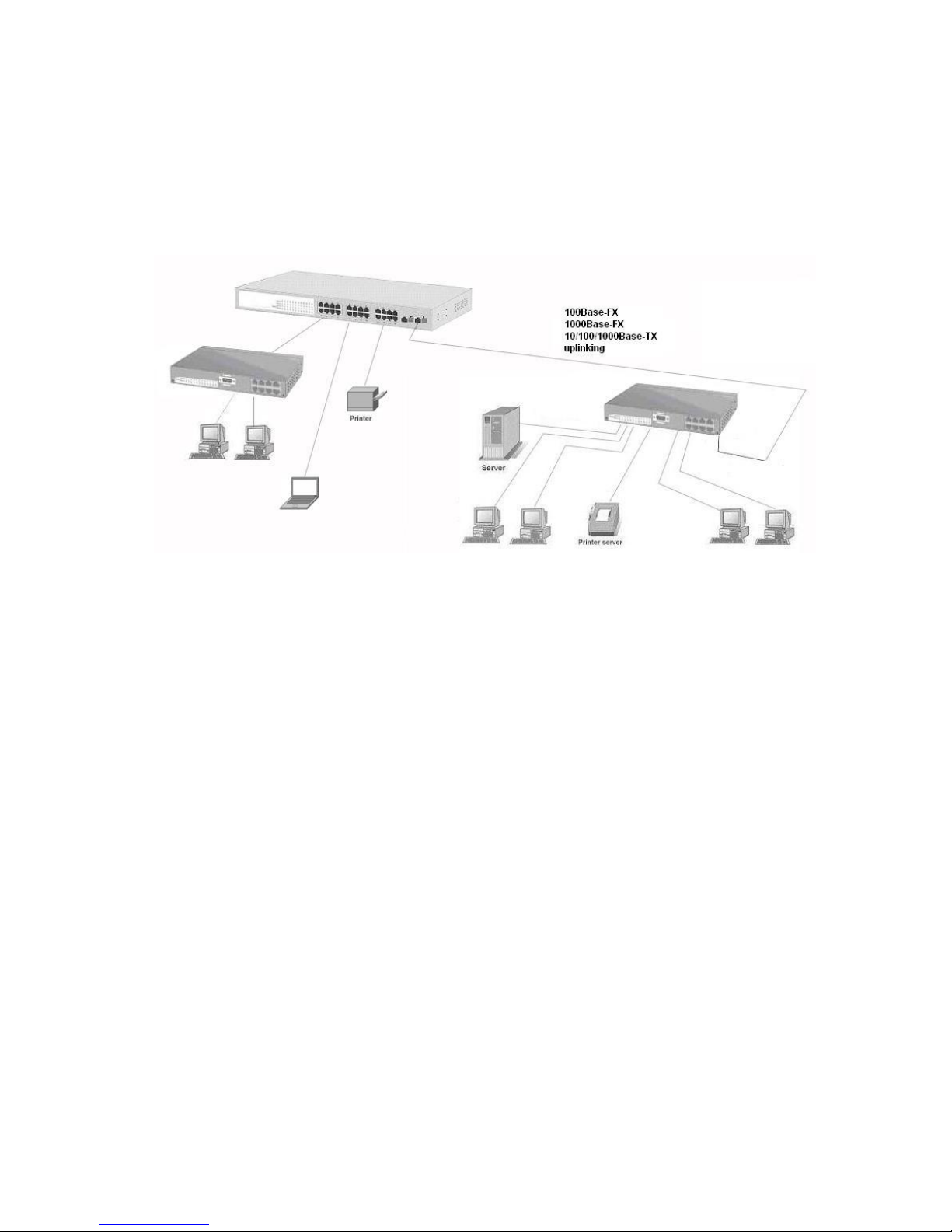
4.1 Desktop Application
The 24 10/100/1000T with 4 1000SFP shared cage SNMP Managed Switch is designed
to be a desktop size switch that is an ideal solution for small workgroup. The Switch can
be used as a stand-alone switch to which personal computers, server, printer server are
directly connected to form small workgroup.
4.2 Segment Application
For enterprise networks where large data broadcast are constantly processed, this
switch is suitable for department user to connect to the corporate backbone.
18
User can connect PCs, workstations, and servers to each other via the 24 10/100/1000T
with 4 1000SFP shared cage SNMP Managed Switch. All the devices in this network can
communicate with each other. Connecting servers to the backbone switch allow other
users to access the data of server.
The switch automatically learns node address, which are subsequently used to filter and
forward all traffic based on the destination address. User can use any of the RJ-45 port
of the 24 10/100/1000T with 4 1000SFP shared cage SNMP Managed Switch to connect
with another Switch or Hub to interconnect each of user‟s small-switched workgroups to
form a larger switched network.

19
Chapter 5 Console Management
5.1 Connecting to the Console Port
Use the supplied RS-232 cable to connect a terminal or PC to the console port. The
connected terminal or PC must support the terminal emulation program.
Connecting the switch to a terminal via RS-232 cable
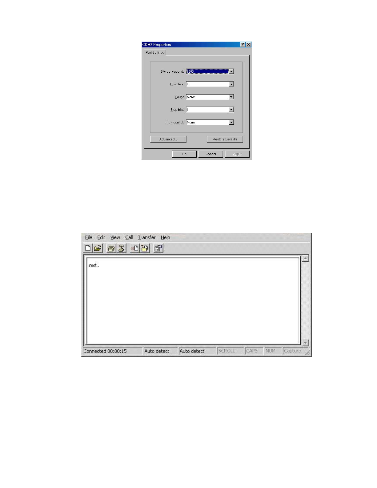
5.2 Login in the Console Interface
When the connection between Switch and PC is ready, turn on the PC and run a terminal
emulation program or Hyper Terminal and configure its communication parameters to
match the following default characteristics of the console port:
Baud Rate: 9600 bps
Data Bits: 8
Parity: none
Stop Bit: 1
Flow control: None
20
The settings of communication parameters
After finishing the parameter settings, click “OK“. When the blank screen shows up, type
in “root” then press enter button to get into command line mode. Please see below
figure for login screen.
CLI command interface
21
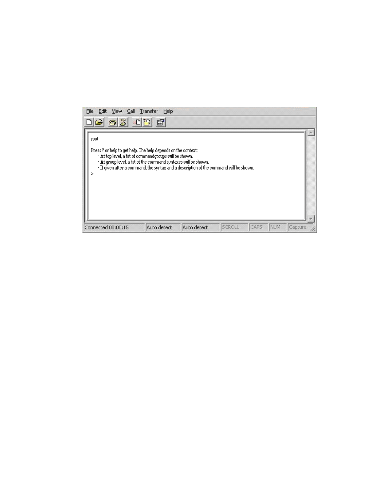
5.3 CLI Management
The system supports console management (CLI command). After you login to the
system, you will see a command prompt.
CLI command interface
5.4 Commands Level:
System
- System commands
Console
- Console commands
Port
- Port commands
MAC
- MAC commands
VLAN
- VLAN commands
Aggr
- Aggregation commands
LACP
- IEEE 802.3ad Link Aggregation commands
RSTP
- IEEE 802.1w Rapid Spanning Tree commands
QoS
-QoS commands
Rate Limit
- Rate Limit commands
Mirror
- Mirror commands
IP
- IP commands

22
Dot1x
- Dot1x commands
Filter
- Filter commands
IGMP
- IGMP Snooping commands
Exit
- Logout

23
Chapter 6 Web-Based Management
This section introduces the configuration and functions of the Web-Based management.
6.1 About Web-based Management
On CPU board of the switch, there is an embedded HTML web site residing in flash
memory, which offers advanced management features and allow users to manage the
switch from anywhere on the network through a standard browser such as Microsoft
Internet Explorer.
The Web-Based Management supports Internet Explorer 6.0 or later version. And, it is
applied for Java Applets for reducing network bandwidth consumption, enhance access
speed and present an easy viewing screen.
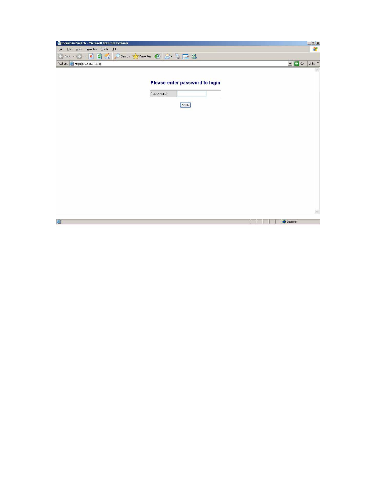
6.2 Preparing for Web Management
Before using web management, install the switch on the network and make sure that any
one of the PCs on the network can connect with the switch through the web browser.
The switch default value of IP, subnet mask and password are as below:
IP Address: 192.168.16.1
Subnet Mask: 255.255.255.0
Default Gateway: 192.168.16.254
Password: root
6.3 System Login
The default login password is root.
24
Login Interface
6.4 System Configuration
The system parameters information as shown below displays the system information and
allows the user to configure the other parameters as well.
MAC Address: The unique hardware address assigned by manufacturer (default).
S/W Version: Displays the Software Version of Kernel.
H/W Version: Displays the Hardware Version of Switch.
Active IP Address: the current IP Address.
Active Subnet Mask: Displays the current IP Subnet Mask.
Active Gateway: Displays the current Gateway.
DHCP Server: Displays the DHCP Server IP Address.
Lease Time Left: Displays the DHCP lease time. After 50% of the lease time has
passed, the client/switch will attempt to renew the lease with the original DHCP
server that it obtained the lease from using a DHCPREQUEST message. Any time

25
the client/switch boots and the lease is 50% or more passed, the client/switch will
attempt to renew the lease. At 87.5% of the lease completion, the client/switch will
attempt to contact any DHCP server for a new lease.
DHCP Enable:
Tick the check box to enable DHCP Client Function.
Fallback IP Address:
Assign the switch IP address (The default IP is 192.168.16.1)
Fallback Subnet Mask:
Assign the switch IP Subnet Mask.
Fallback Gateway:
Assign the switch Gateway (The default value is
192.168.16.254).
TFTP Server Enabled:
Tick this check box to enable the TFTP server function.
Management VLAN (1 ~ 4094):
Assign a number of VLAN group between 1 and
4094. It is used for Remote Management Security; in fact, it gives the permission to
access the switch only when the port of VLAN group ID is equal to the Management
VLAN ID
Name:
Assign the name of the switch.
Password:
Web GUI login password. The default password is
root.
Inactivity Timeout:
Set the timeout period for security in number between 60 and
10000 seconds. It means will not logout when set 0.
And then, click
Apply
to have the configuration taken effect.
Or, click
Refresh
to reset the configuration before applying.
6.5 Console Info
This page displays the related information of the console port settings which you have
set in the Console Management segment.
6.6 Port Statistics
The following information provides the current port statistics
Press
Clear
button to clean all counts.

26
And then, click
Refresh
to get the new setting information as below:
Port Statistics interface
6.7 Port Configuration
This page displays the port status of linking, and allows the user to set negotiation mode,
to enable flow control and max frame function.
Link:
Displays the current connection speed.
Mode:
Pull down the selection item to choose the negotiation mode.
Flow Control:
Tick this check box to enable flow control function.
Jumbo Mode:
Tick this check box to enable jumbo mode for Maximum Frame Size.
Drop frames after excessive collisions
: When this check box is ticked, the switch

27
will drop the frames after excessive collisions.
Click
Refresh
to get the newest status.
Port Configuration interface

28
6.8 Port Trunk Configuration
Port trunk allows multiple links to be bundled together and act as a single physical link to
increase throughput. It provides load balancing, and redundancy of links in a switched
inter-network. Actually, the link does not have an inherent total bandwidth equal to the sum
of its component physical links. Traffic in a trunk is distributed across an individual link
within the trunk in a deterministic method that called a hash algorithm. Traffic pattern on the
network should be considered carefully before you apply it. When a proper hash algorithm
is used, traffic is kind of randomly decided to be transmitted across either link within the
trunk and load balancing will be seen.
Grouping the members of Trunk. Normal means the port is not a trunk port.
And then, click
Apply
to apply the configuration.
Or, click
Refresh
to reset the configuration before applying.
Port Trunk interface

29
6.9 Port Mirroring
Analysis Port:
Select a port for analyzing other ports.
Monitor Rx and TX:
Tick the check box for enabling the received/transmitted
packets of the port to be monitored.
And then, click
Apply
to apply the configuration.
Or, Click
Refesh
to reset the configuration before applying.
Port Mirroring interface
6.10 VLAN Setting
A Virtual LAN (VLAN) is a logical network grouping that limits the broadcast domain,
which would allow user to isolate network traffic, and therefore only the members of the
VLAN will receive traffic from the members of the same VLAN. Basically, creating a
VLAN from a switch is logically equivalent to reconnecting a group of network devices to
another Layer 2 switch. However, all the network devices are still plugged into the same

30
switch physically.
Assign the VLAN ID in number between 1 and 4094.
Click
add all
to tick the 24 check boxes at the same time.
Click
clear all
to clear all of the ticks in the 24 check boxes.
Grouping the members of the VLAN.
In the filed of “Quick Search Vlan Entry”, please key in the Vlan ID and press
Search
to find the Vlan Entry.
And then, click
Apply
to bring up the configuration interface as below:
VLAN Setting interface
6.10.1 VLAN Port Setting
Change to “VLAN Port Setting” tab to adjust the VID Setting.
PVID:
Enter the Port VLAN ID between 1 and 4094.
Awareness:
Enable the awareness that ports will strip the VLAN tag from received
frames and insert the tag in the transmitted frames (PVID). Disable the awareness
that ports will not strip the tag from received frames or insert the tag in the
transmitted frames.
Frame Type:
Set the outgoing frames type.

31
All: All type of frames.
Tagged: Outgoing frames with VLAN-Tagged.
After that, click
Apply
to have the configuration taken effect.
Or, click
Refresh
to reset the configuration before applying.
VLAN Port Setting interface
6.11 LACP Setting

32
The Link Aggregation Control Protocol (LACP) is a computer networking term and is part
of IEEE specification 802.3ad that allows bundling several physical ports together to
form a single logical channel. LACP allows a network switch to negotiate an automatic
bundle by sending LACP packets to the peer. LACP is a protocol implementation in OSI
layer 2 which controls through which physical links the traffic will be routed.
Protocol Enabled:
Tick the check box to enable the LACP protocol of the port.
State Activity:
Pull down the selection item to set the activity state as active or
passive. When the state is set as active, the port sends LACP packets to its peer
actively. Otherwise, the port will not send LACP packets out unless it receives an
LACPDU from its peer.
Key Value (auto | 1 - 255):
The LACP key determines which ports potentially can
aggregate together.
And then, click
Apply
to have the configuration taken effect.
Or, click
Refresh
to reset the configuration before applying.

33
LACP Setting interface
6.11.1 LACP Status
When the LACP aggregator has been set up, the LACP status information will display as
below.
Protocol Active:
Displays whether the LACP protocol is active.
Partner Port Number:
Displays the partner port number which is connecting to this
port.
Operational Port key:
The LACP key determines which ports potentially can

34
aggregate together.
LACP Status interface

35
6.12 RSTP Configuration
The Rapid Spanning Tree Protocol (RSTP) is an evolution of the Spanning Tree Protocol
and provides for faster spanning tree convergence after a topology change. The system
also supports STP and the system will automatically detect the connected device that is
running STP or RSTP protocol.
6.12.1 RSTP Configuration Tab
System Priority:
A value used to identify the root bridge. The bridge with the lowest
value has the highest priority and is selected as the root. If the value has being
changed, user has to reboot the switch. The value must be multiple of 4096
according to the protocol standard rule.
Hello Time (1-10):
The scale of 1~10 sec will be set as a period of time that how
often the switch broadcasts hello messages to other switches.
Max Age (6-40):
The number of seconds (from 6~ 40) which determines the amount
of time that protocol information received on a port is stored by the switch.
Forward Delay Time (4-30):
The number of seconds (from 4 ~ 30) which
determines how long each of the listening and learning states will last before the
port begins forwarding.
Force version:
Select the RSTP default protocol. Normal means RSTP protocol.
Compatible means it‟s compatible with STP protocol.
RSTP Configuration interface

36
6.12.2 RSTP Port Configuration
Protocol Enable:
Enable or disable the RSTP protocol for the port.
Edge:
Having set the port as an edge port which directly connected to end stations
cannot create bridging loop in the network. To configure the port as an edge port,
tick the check box.
Path Cost:
The cost of the path to the other bridge from this transmitting bridge at
the specified port. Enter a number from 1 through 200,000,000.
And then, click
Apply
to apply the configuration.
Or, click
Refresh
to reset the configuration before applying.
RSTP Port Configuration interface
6.12.3 RSTP Status Tab

37
Click
Refresh
to get the newest configuration information. Also, the RSTP Bridge
Overview will display as below.
RSTP Bridge Overview
Bridge ID:
Displays the ID produced by the algorithm of MAC address and priority
that is used in the STP/RSTP structure.
Hello Time:
Displays the period of time in seconds that how often the switch
broadcasts hello messages to other switches.
Max Age:
Displays the number of seconds which determines the amount of time
that protocol information received on a port stored by the switch.
Fwd Delay:
Displays the number of seconds which determines how long each of the
listening and learning states will last before the port begins forwarding.
Topology:
Displays the status of the topology.
Root ID:
Displays the ID of the root.
RSTP Port Status
Port/Group: Displays the port number and its group number.
Path Cost: The cost of the path to the other bridge from this transmitting bridge at
the specified port.
Edge port: The port directly connected to end stations cannot create bridging loop
in the network.
P2P Port: Some of the rapid state transactions that are possible within RSTP are
dependent upon whether the port concerned can only be connected to one other
bridge exactly (i.e. it is served by a point-to-point LAN segment), or can be
connected to two or more bridges (i.e. it is served by a shared medium LAN
segment). This function allows the P2P status of the link to be manipulated
administratively. True means P2P enabled. False means P2P disabled.
Protocol: Displays the protocol being used.
Port State: Displays whether the port is the STP mathematic calculation or not.
Click
Apply
to have the setting taken effect.

38
RSTP Port Status interface
6.13 SNMP Setting
Simple Network Management Protocol (SNMP) is the protocol developed to manage

39
nodes (servers, workstations, routers, switches and hubs etc.) on an IP network. SNMP
enables network administrators to manage network performance, find and solve network
problems, and plan for network growth. Network management systems learn of problems
by receiving traps or change notices from network devices implementing SNMP.
SNMP Setting interface
SNMP enabled:
Tick the check box to enable SNMP.
SNMP Contact:
Enter the name of a person or organization.
SNMP Location:
Enter the location of the switch.
SNMP Trap destination:
Assign the IP address of the destination for receiving the
SNMP trap.
SNMP Read Community:
Read only community string. Enables requests
accompanied by this string to display MIB-object information.
SNMP Write Community:
Read/Write. Enables requests accompanied by this
string to display MIB-object information and to set MIB objects.
SNMP Trap Community:
Enables requests accompanied by this string to receive
SNMP trap.

40
6.14 QoS Configuration
In this segment, you can configure QoS policy setting, QoS DSCP setting, priority queue
service, and QoS Vlan tag.
Mode:
Select the QoS mode—port, DSCP, or vlan tag.
Port Priority:
Select the priority level—low, normal, medium, or high.
And then, click
Apply
to apply the configuration.
Or, click
Refresh
to reset the configuration before applying.
QoS Configuration interface

41
6.14.1 QoS DSCP Mapping
Change to Qos DSCP Mapping tab:
DSCP [0- 63]:
The system provides 0~63 TOS priority level. When the IP
packet is received, the system will check the TOS level value in the IP packet
that has received. For example, user set the TOS level 25 is high. The port 1 is
following the TOS priority policy. When the packet received by port 1, the
system will check the TOS value of the received IP packet. If the TOS value of
received IP packet is 25 (priority = high), and then the packet priority will have
highest priority.
Priority:
Select the priority level—high, medium, low, or normal.
And then, click
Apply
to apply the configuration.
Or, Click
Refesh
to reset the configuration before applying.
QoS DSCP Mapping interface

42
6.14.2 Priority Queue Service
Change to Priority Queue Service tab:
You can choose the means for priority queue. There are two radio buttons selection
item—„All High Before Low’ & „Weighted Round Robin/WRR’—in each port column.
When „All High Before Low’ is selected, the low priority queues will be served before all
of the high priority queue services are finished. Or otherwise, you can check the
Weighted Round Robin/WRR radio button for the queue service to be served in
compliance with WRR.
Priority Queue Service interface

43
And then, click
Apply
to apply the configuration.
Or, Click
Refesh
to reset the configuration before applying.
6.14.3 QoS Vlan Tag
You can pull down the selection item from Vlan Tag 0 to Vlan Tag 7 of each port to
assign the priority. There are 4 priority selections—low, normal, medium and high.

44
QoS VLAN Tag Priority Mapping interface
6.15 IGMP Configuration
IGMP Enabled:
Tick the check box to enable IGMP function.
Router Ports:
Tick the check box beside the port number for checking.
Unregistered IPMC Flooding enabled:
The default state is checked to enable the
unregistered IP Multicast flooding.
IGMP Snooping Enabled:
Tick the check box to enable IGMP Snooping function.
IGMP Querying Enabled:
Tick the check box to enable IGMP Querying function.

45
And then, click
Apply
to apply the configuration.
Or, Click
Refesh
to reset the configuration before applying.
IGMP Configuration interface
6.15.1 IGMP Status
Querier:
Displays the status of the querier.
Queries transmitted:
Displays the amount of the transmitted queries.
Queries received:
Displays the amount of the received queries.
v1 ~ v3 Reports:
Displays the amount of IGMP reports issued from the client.
v2 Leaves:
Displays the amount of leave message issued from the client.
Click
Refesh
to reset the status.

46
IGMP Status interface
6.16 Rate Limit Configuration
Storm Control (Number of frames per second)
ICMP Rate:
Assign the rate of transmitting packets of ICMP. The rates are in
the range of 1K ~ 1024K fps or No limit.
Learn Frames Rate:
Assign the rate of learning frames. The rates are in the
range of 1K ~ 1024K fps or No limit.
Broadcast Rate:
Assign the rate of broadcasting packets. The rates are in the
range of 1K ~ 1024K fps or No limit.
Multicast Rate:
Assign the rate of multicasting packets. The rates are in the
range of 1K ~ 1024K fps or No limit.
Flooded unicast Rate:
Assign the rate of flooded unicasting packets. The
rates are in the range of 1K ~ 1024K fps or No limit.
Bandwidth Control (Number of bits per second)
TX:
Select the TX rates in the range of 128K ~ 3968K bps or No limit.
RX:
Select the RX rates in the range of 128K ~ 3968K bps or No limit.
And then, click
Apply
to apply the configuration.
Or, Click
Refesh
to reset the configuration before applying.

47
Rate Limit interface
6.17 Security Configuration
Source IP Security
Mode:
Select the source IP mode—Static, DHCP, or Disabled.
IP Address:
When Mode is set in Static mode, the user has to assign an IP
address manually.
IP Mask:
When Mode is set in Static mode, the user has to assign the IP mask
manually.
DHCP Server Allowed:
Tick this check box to allow the devices whose IP address
assigned by DHCP server to access this port.

48
And then, click
Apply
to apply the configuration.
Or, Click
Refesh
to reset the configuration before applying.
Filter Configuration interface
6.18 802.1X Configuration
IEEE 802.1X is an IEEE standard for port-based Network Access Control; it is part of the
IEEE 802 (802.1) group of protocols. It provides authentication to devices attached to a
LAN port, establishing a point-to-point connection or preventing access from that port if
authentication fails. IEEE 802.1X is available on certain network switches, and can be
configured to authenticate hosts which are equipped with supplicant software, denying

49
unauthorized access to the network at the data link layer.
Mode:
Disable or enable IEEE 802.1x authentication.
RADIUS IP:
Assign the Radius Server IP address.
RADIUS UDP Port:
Assign the UDP destination port for authentication requests to
the specified Radius Server.
RADIUS Secret:
Assign an encryption key for using during authentication sessions
with the specified radius server. This key must match the encryption key used on the
Radius Server.
Admin State:
Select the state of the port.
Force Authorized:
The specified port is required to be held in the authorized
state.
Force Unauthorized:
The specified port is required to be held in the
unauthorized state
Auto:
The specified port is set to the authorized or unauthorized state in
accordance with the outcome of an authentication exchange between the
Supplicant and the authentication server.
Re-authenticate:
Restart authentication process for the port.
Force Reinitialize:
Restart a complete authentication process for the port.
Statistics:
Click to view each port statistic.
Re-authenticate All:
Restart a complete authentication process for all of the ports.
Force Reinitialize All:
Restart authentication process for all of the ports.
And then, click
Apply
to apply the configuration.
Or, click
Refresh
to reset the configuration before applying.

50
802.1X Configuration interface
6.18.1 802.1X Parameters
Click on the tab of 802.1X Parameters to change to configure the 802.1X Parameters
page.
Reauthentication Enable:
Enable the re-authentication mode.
Reauthentication Period (1~3600 seconds):
Set the period of time after which
clients connected must be re-authenticated.
EPA Timeout (1~255 seconds):
Set the period of time the switch waits for a
supplicant response to an EAP request.

51
And then, click
Apply
to apply the configuration.
Or, click
Refresh
to reset the configuration before applying.
802.1X Parameters interface
6.18.2 802.1X Statistics
Click the tab of 802.1X Statistics to change to the 802.1X Statistics page to view the
detail information.
Click
Refresh
to get the newest statistics.

52
802.1X Statistics interface
6.19 MAC Address Table Control
MAC Address Entry No:
The index of the MAC address table.
MAC Address:
The MAC address of the entry.
Port:
Displays the port number from which the MAC address was learned.
VLAN ID:
Displays the VLAN ID of the port.
Type:
Displays the information of the MAC address that was learned automatically
by the switch or built by user.
Click
Refesh
to reset the status.

53
Dump MAC Address Table interface
6.19.1 Static MAC Address Entries in Permanent Table
You can add/delete MAC address entries manually to maintain the MAC address table.
Click
Refesh
to get the newest information.

54
Static MAC Address Entries in Permanent Table interface
6.20 TFTP Firmware Upload
It provides the functions that allow you to upgrade the switch firmware. Before upgrading,
make sure the TFTP server is ready and the firmware image is located on the TFTP
server. Moreover, the check box beside the item of „TFTP Server Enabled‟ in „System
Configuration‟ must be ticked.
TFTP Server IP Address: Type in your TFTP server IP.
Firmware File Name: Type in the name of the firmware image file.
Click
Upload
.
TFTP Firmware Upload interface

55
6.20.1 TFTP Firmware Backup
It provides the functions that allow user to backup the switch firmware. Before doing that,
make sure the TFTP server is ready.
TFTP Server IP Address: Type in your TFTP server IP.
Firmware File Name: Type in the name of the firmware image file.
Click
Backup
.
TFTP Firmware Backup interface
6.20.2 TFTP Configuration Restore
It provides the functions that allow you to restore the switch configuration. Before
Restoring, make sure the TFTP server is ready and the previous configuration file is
located on the TFTP server.
TFTP Server IP Address: Type in your TFTP server IP.
Restore File Name: Type in the name of the configuration file.
Click
Restore
.
TFTP Configuration Restore interface

56
6.20.3 TFTP Configuration Backup
It provides the functions that allow user to backup the switch configuration. Before doing
that, make sure the TFTP server is ready.
TFTP Server IP Address: Type in your TFTP server IP.
Backup File Name: Type in the name of the backup image file.
Click
Backup
.
TFTP Configuration Backup interface
6.21 Software Upload
The system provides the Web GUI firmware upgrade function which allows user to
upgrade the switch firmware.
Click
Browse...
to locate the firmware.
And then, press
Upload
to update the firmware.
Software Upload interface

57
6.21.1 Configuration Upload/Download
The system provides the Web GUI configuration file transfer function which would allow
user to backup and restore the switch configuration.
Click
Browse
to locate the file.
And then, press
Upload
to upload the file.
Configuration Upload interface
And then, press
Yes
to update the loaded file.
For restoring the configuration, press
Download
to restore the file.
Configuration Download interface

58
6.22 Factory Default
Reset the switch to default configuration.
Click
Yes
to reset all of the configurations to the default value.
Or click
KeepIP
to reset all of the configurations to the default value except IP
address.
Factory Default interface
6.23 Warm Restart
Reboot the switch in software reset to have the configurations taken effect.
Click
Yes
to restart the system.
Warm Restart interface
6.24 Logout
To log out the system, just click the “Logout” item in the tree menu on the left side, and
the system will display the login interface as below.
Logout interface

59
Troubleshooting
This section is intended to help user solve the most common problems on the 24
10/100/1000T with 4 1000SFP shared cage SNMP Managed Switch.
Incorrect connections
The switch port can automatically detect straight or crossover cable when user link
switch with other Ethernet device. As for the RJ-45 connector, it should use correct UTP
or STP cable; 10/100TX port use 2-pairs twisted cable, while Gigabit 1000T port use 4
pairs twisted cable. If the RJ-45 connector is not correctly pinned on right position, then
the link will fail. As for fiber connector, please notice the fiber cable mode and fiber
module should match.
Faulty or loose cables
Look for loose or obviously faulty connections. If they appear to be OK, make sure the
connections are snug. If that does not correct the problem, try a different cable.
Non-standard cables
Non-standard and miss-wired cables may cause numerous network collisions and other
network problem, and can seriously impair network performance. A cable tester is a
recommended tool for network installation.
RJ-45 ports: Use unshielded twisted-pair (UTP) or shield twisted-pair (STP) cable for
RJ-45 connections: 100Ω Category 3, 4 or 5 cable for 10Mbps connections, 100Ω
Category 5 cable for 100Mbps connections, or 100Ω Category 5e/above cable for
1000Mbps connections. Also be sure that the length of any twisted-pair connection does
not exceed 100 meters (328 feet).
Improper Network Topologies

60
It is important to make sure that you have a valid network topology. Common topology
faults include excessive cable length and too many repeaters (hubs) between end nodes.
In addition, you should make sure that your network topology contains no data path
loops. Between any two end nodes, there should be only one active cabling path at any
time. Data path loops will cause broadcast storms that will severely impact your network
performance.
Diagnosing LED Indicators
To assist in identifying problems, the Switch can be easily monitored through panel
indicators, which describe common problems the user may encounter and where the
user can find possible solutions.
If the power indicator does not light on when the power cord is plugged in, you may have
a problem with power outlet, or power cord. However, if the switch powers off after
running for a while check for loose power connections, power losses or surges at power
outlet. If you still cannot resolve the problem, contact your local dealer for assistance.

61
Appendix A- Command Sets
System Commands
Commands
Description
Example
configuration [all]
Show system name, software
version, hardware version and
management
MAC address. Optionally show the
full configuration
system>configuration
or
system>configuration all
restore default [keepip]
Restore factory default
configuration.
or
Restore to default without
changing the current IP
system>restore default
or
system>restore default keepip
name [<name>]
Set or show the system name
(String of up to 16 characters).
system>system name
or
system>system name 123
reboot
Reboot the switch.
system>reboot
xmodem
Start XMODEM receiver on this
switch.
Now send firmware image or
configuration file over this
serial line where the switch will
save it in flash.
This implementation of XMODEM
uses CRC16 checksum and
128bytes buffer.
system>xmodem
SNMP [enable|disable]
Activate or deactivate the SNMP.
[enable|disable]: Enable/disable
system>snmp
or
system>snmp enable

62
SNMP (default: Show SNMP
mode).
Trap [<IP Address>]
Set or show SNMP traps
destination.
<IP Address>: IP address to send
traps to. (default: Show trap
configuration)
system>trap
or
system>trap 192.168.16.66
readcommunity
[<community string>]
Set or show SNMP read
community string.
[<community string>]: New
community string. (default: Show
current value).
system>readcommunity
or
system>readcommunity aaa
writecommunity
[<community string>]
Set or show SNMP write
community string.
[<community string>]: New
community string. (default: Show
current value).
system>writecommunity
or
system>writecommunity bbb
trapcommunity
[<community string>]
Set or show SNMP trap
community string.
[<community string>]: New
community string. (default: Show
current value).
system>trapcommunity
or
system>trapcommunity ccc
Console Commands
Commands
Description
Example
configuration
Show configured console
password and timeout.
console>configuration
password
Set or show the console password.
console>password

63
[<password>]
The empty string ("") disables the
password check.
[<password>]: Password string of
up to 16 characters.
or
console>password aaa
timeout [<timeout>]
Set or show the console inactivity
timeout in seconds. The value zero
disables timeout.
[<timeout>]: Timeout value in
seconds, 0,60-10000.
console>timeout
or
console>timeout 100
prompt
[<prompt_string>]
Set or show the console prompt
string.
[<prompt_string>]: Command
prompt string of up to 10
characters.
console>prompt
or
console>prompt $
Port Commands
Commands
Description
Example
configuration
[<portlist>]
Show the configured and current
speed, duplex mode, flow control
mode and state for the port.
[<portlist>]: Port list (Default: All
ports).
port>configuration
or
port>configuration 3
mode [<portlist>]
[<mode>]
Set or show the speed and duplex
mode for the port.
[<portlist>]: Port list (Default: All
ports).
[<mode>]: Port speed and duplex
port>mode
or
port>mode 1000fdx
or
port>mode 1 1000fdx
or

64
mode (Default: Show configured
and current mode).
10hdx: 10 Mbit/s, half duplex.
10fdx: 10 Mbit/s, full duplex.
100hdx: 100 Mbit/s, half duplex.
100fdx: 100 Mbit/s, full duplex.
1000fdx: 1 Gbit/s, full duplex.
auto: Auto negotiation of speed
and duplex.
port>1-20 1000fdx
flow control
[<portlist>]
[enable|disable]
Set or show flow control mode for
the port.
[<portlist>]: Port list (default: All
ports).
[enable|disable]: Enable/disable
flow control (default: Show flow
control mode).
port>flow control
or
port>flow control enable
or
port>flow control disable
or
port>flow control 3 enable
or
port>flow control 3 disable
state [<portlist>]
[enable/disable]
Set or show the state for the port.
[<portlist>]: Port list (default: All
ports).
[enable|disable]: Enable or disable
port state (default: Show state).
port>state
or
port>state enable
or
port>state disable
or
port>state 2 enable
or
port>state 2 disable
jumbomode
[<portlist>]
[enable/disable]
Set or show the jumbomode for
frames received on the port.
[<portlist>]: Port list (default: All
ports).
port>jumbomode
or
port>jumbomode 1 enable
statistics [<portlist>]
[clear]
Show or clear statistics for the
port.
port>statistics
or

65
[<portlist>]: Port list (default: All
ports).
[clear]: Clear port statistics
(default: Show statistics).
port>statistics 2
or
port>statistics clear
excessive collisions
drop [enable|disable]
Description:
Enable or disable drop of frames
when excessive collisions occur in
half duplex mode.
[enable|disable]: Enable/disable
frame drop (default: Show
Excessive Collisions Drop mode).
port>excessive collisions
drop
or
port> excessive collisions
drop enable
or
port> excessive collisions
drop disable
MAC Commands
Commands
Description
Example
configuration
Show the permanently stored MAC
table and the MAC aging timer.
mac>configuration
add <macaddress>
<portlist>|none [<vid>]
Add permanent MAC address and
VLAN ID on ports.
<macaddress>: MAC address, 12
digit hex string, optionally
separated with dashes or colons
(e.g. 010203ABCDEF or
01-02-03-AB-CD-EF or
01:02:03:AB:CD:EF).
<portlist>: Port list. Use "none" to
specify no ports.
[<vid>]: VLAN ID, 1-4095 (default:
1).
mac>add 000000000001 2
delete <macaddress>
Delete MAC address and VLAN
mac>delete 000000000001 2

66
[<vid>]
ID.
<macaddress>: MAC address, 12
digit hex string, optionally
separated with dashes or colons
(e.g. 010203ABCDEF or
01-02-03-AB-CD-EF or
01:02:03:AB:CD:EF).
[<vid>]: VLAN ID (default: All).
lookup <macaddress>
[<vid>]
Lookup MAC address and VLAN
ID.
<macaddress>: MAC address, 12
digit hex string, optionally
separated with dashes or colons
(e.g. 010203ABCDEF or
01-02-03-AB-CD-EF or
01:02:03:AB:CD:EF).
[<vid>]: VLAN ID, 1-4095 (default:
1).
mac>lookup 000000000001 2
table <vidlist>
Show the MAC address table for
VLAN ID list.
<vidlist>: VLAN ID list.
mac>table 1
flush
Removes non-locked entries from
the switch MAC table.
mac>flush
agetime [<agetime>]
Set or show the MAC age timer in
seconds. The value zero disables
ageing.
[<agetime>]: Age timer in seconds,
0 or 10-65535 (default: Show
timer).
mac>agetime
or
mac>agetime 100

67
VLAN Commands
Commands
Description
Example
configuration
[<portlist>]
Show the VLAN aware mode, port
VLAN ID and accepted frame type
for the port and the permanently
stored VLAN table.
vlan>configuration
or
vlan>configuration 2
add <vidlist>
[<portlist>]
Add VLAN entry and include ports
in member set.
<vidlist>: VLAN ID list.
[<portlist>]: Port list (default: All
ports).
vlan>add 2 1
or
vlan>add 2 2-4
or
vlan>add 2 2-4,6
or
vlan>add 2 all
delete <vidlist>
Delete VLAN entry (all ports
excluded from member set).
<vidlist> : VLAN ID list.
vlan>delete 2
lookup <vidlist>
Lookup VLAN entry and show port
list.
<vidlist> : VLAN ID list.
vlan>lookup 2
aware [<portlist>]
[enable|disable]
Set or show the VLAN awareness
mode for the port. VLAN aware
ports will strip the VLAN tag from
received frames and insert the tag
in transmitted frames (except
PVID). VLAN unaware ports will
not strip the tag from received
frames or insert the tag in
transmitted frames.
[<portlist>]: Port list (default: All
ports).
vlan>aware 1 enable
or
vlan>aware all enable

68
[enable|disable]: Enable/disable
VLAN awareness (default: Show
awareness).
pvid [<portlist>]
[<vid>|none]
Set or show the port VLAN ID.
Untagged frames received on the
port will be classified to this VLAN
ID. Frames classified to this VLAN
ID will be sent untagged on the
port.
[<portlist>]: Port list (default: All
ports).
[<vid>|none]: Port VLAN ID,
1-4095 (default: Show PVID).
The 'none' option can be used for
trunk links.
vlan>pvid 1 2
or
vlan>pvid all 2
frame type [<portlist>]
[all|tagged]
Set or show the accepted frame
type for the port.
[<portlist>]: Port list (default: All
ports).
[all|tagged]: Accept all or only
tagged (default: Show frame type).
vlan>frame type 1 tagged
or
vlan>frame type all tagged
or
vlan>frame type 1 all
or
vlan>frame type all all
ingress filtering
[<portlist>]
[enable|disable]
Set or show VLAN ingress filtering
for the port.
[<portlist>]: Port list (default: All
ports).
[enable|disable]: Enable or disable
VLAN ingress filtering (default:
Show current setting).
vlan>ingress filtering 1
or
vlan>ingress filtering 1 enable

69
Aggr Commands
Commands
Description
Example
configuration
Shows the aggregation groups and
the aggregation mode.
aggr>configuration
add <portlist>
Add link aggregation group
including ports.
<portlist>: Aggregation port list.
aggr>add 1-4
delete <portlist>
Delete link aggregation group.
<portlist>: Port list. Aggregations
including any of the ports will be
deleted.
aggr>delete 1-4
lookup <portlist>
Lookup and display link
aggregation group.
<portlist>: Port list. Aggregations
including any of the ports will be
shown.
aggr>lookup 1-4
mode [smac|dmac|xor]
Set or show link aggregation traffic
distribution mode.
[smac|dmac|xor]: Aggregation
mode, SMAC, DMAC or XOR
(default: Show mode).
aggr>mode smac
or
aggr>mode dmac
or
aggr>xor
LACP Commands
Commands
Description
Example
configuration
[<portlist>]
Show LACP configuration.
[<portlist>]: Port list (Default: All
lacp>configuration
or
lacp>configuration 2

70
ports).
mode [<portlist>]
[enable|disable]
Enable or disable the LACP
protocol on ports <portlist>.
[<portlist>]: Port list (Default: All
ports).
[enable|disable]: Enable or
disable.
lacp>mode 3 enable
or
lacp>mode 1-4 enable
or
lacp>mode 1-4 disable
key [<portlist>]
[<key>|auto]
Set the LACP key on ports
<portlist>.
[<portlist>]: Port list (Default: All
ports).
[<key>]: Number between 1 - 255.
Auto means autogenerated key.
lacp>key 1 200
or
lacp>key 1-4 200
or
lacp>key auto
status activity
Show the port of LCAP group
states.
lacp>status activity
status
Show LACP group and port states.
lacp>status
statistics
Show LACP protocol port
statistics.
lacp>statistics
RSTP Commands
Commands
Description
Example
configuration
[<portlist>]
Show RSTP configuration.
[<portlist>]: Port list (Default: All
ports).
rstp>configuration
or
rstp>configuration 2
sysprio [<sysprio>]
Set or show the RSTP System
Priority.
[<sysprio>]: Number between 0 61440 in increments of 4096
rstp>sysprio
or
rstp>sysprio 4096

71
This provides for 16 distinct
values: 0, 4096, 8192, 12288,
16384, 20480, 24576, 28672,
32768, 36864, 40960, 45056,
49152, 53248, 57344 and 61440.
hellotime [<secs>]
Set or show the RSTP System
Hello time.
[<secs>]: Number between 1 - 10
(default is 2)
rstp>hellotime
or
rstp>hellotime 1
maxage [<hops>]
Set or show the RSTP System
Max Age.
[<hops>]: Number between 6 - 40
(default is 20)
rstp>maxage
or
rstp>maxage 6
fwddelay [<secs>]
Set or show the RSTP System
Forward delay.
[<secs>]: Number between 4 - 30
(default is 15)
rstp>fwddelay
or
rstp>fwddelay 4
version
[normal|compat]
Set or show the RSTP protocol
version to use.
[<version>]: normal - use RSTP,
compat - compatible with old STP
rstp>version
or
rstp>version compat
or
rstp>version normal
mode [<portlist>]
[enable|disable]
Enable or disable the RSTP
protocol on ports <portlist>.
[<portlist>]: Port list (Default: All
ports).
[enable|disable]: Enable or
disable.
rstp>1 enable
or
rstp> all enable
or
rstp>all disable
aggr [enable|disable]
Enable or disable the RSTP
rstp>aggr enable

72
protocol on aggregated links.
[enable|disable]: Enable or
disable.
edge [enable|disable]
Expect the port to be an edge port
(an end station) or a link to another
STP device.
[enable|disable]: End-station or
bridge.
rstp>edge 1 disable
or
rstp>edge 1 enable
or
rstp>edge all enable
pathcost [<portlist>]
[<pathcost>|auto]
Set the RSTP pathcost on ports
<portlist>.
[<portlist>]: Port list (Default: All
ports).
[<pathcost>]: Number between 1 -
200000000. Auto means
autogenerated pathcost
rstp>pathcost 1 1000
or
rstp>pathcost all 1000
or
rstp>pathcost all all
mcheck <portlist>
Force a recheck of the RSTP
protocol on the ports in <portlist>.
<portlist>: List of ports.
rstp>mcheck 1
or
rstp>mcheck all
status
Show RSTP bridge instances and
port states.
rstp>status
statistics
Show RSTP bridge instance and
port statistics.
rstp>statistics
QoS Commands
Commands
Description
Example
configuration
[<portlist>]
Show the configured QoS mode,
VLAN user priority mapping,
default class, default VLAN user
qos>configuration 1
or
qos>configuration

73
priority and DSCP mapping for the
port.
[<portlist>]: Port list (default: All
ports).
mode [<portlist>]
[tag|port|diffserv]
Set or show the QoS mode for the
port.
[<portlist>]: Port list (default: All
ports).
[tag|port|diffserv]: Enable tag, port
or IP differentiated services class
of service for the port (default:
Show mode).
qos>mode
or
qos>mode 1-4
or
qos>mode 1 tag
or
qos>mode all tag
or
qos>mode all port
or
qos>mode all diffserv
tagprio [<portlist>]
[<tagpriolist>]
[<class>]
Set or show the VLAN user priority
mapping.
[<portlist>]: Port list (default: All
ports).
[<tagpriolist>]: VLAN user priority
list, 0-7 (default: All user priorities).
[<class>]: Internal class of service
(default: Show class).
qos>tagprio
or
qos>tagprio 1-4
or
qos>tagprio 1-24 0-1 high
or
qos>tagprio 1-24 2-3 midium
or
qos>tagprio 1-24 4-5 normal
or
qos>tagprio 1-24 6-7 low
diffserv [<dscpno>]
[<class>]
Set or show the IP Differentiated
Services mapping.
[<dscpno>]: IP DSCP number,
0-63 (default: All DSCP values).
[<class>]: Internal class of service
qos>diffserv
or
qos>diffserv 0 high
or
qos>diffserv 1 midium
or

74
(default: Show class).
qos>diffserv 2 normal
or
qos>diffserv 3 low
priority queue service
[<portlist>] [all high
before low|<low
wrr:normal wrr
:medium wrr:high
wrr>]
Set or show weighted rate ratio
[<portlist>]: Port list (default: All
ports)
.
[<all high before
low>|<low:normal:medium:high>]:
wrr 1,2,4,8 (default: show wrr
setting).
qos>priority queue service
1-4
or
qos>priority queue service
1-4 all high before low
or
qos>priority queue service
1-4 1:2:4:8
Mirror Commands
Commands
Description
Example
configuration
Show the mirror destination port
and mirror mode for source ports.
mirror>configuration
port [<port>]
Set or show the mirror destination
port.
[<port>]: Mirror destination port
(default: Show mirror port).
mirror>mirror port 12
or
mirror>mirror port
source [<portlist>]
[enable|disable]
Set or show the source port mirror
mode.
[<portlist>]: Source port list
(default: All ports).
[enable|disable]: Enable/disable
mirroring of frames received on
port (default: Show mirror mode).
mirror>source 1 enable
or
mirror>source
or
mirror>source 1-10
or
mirror>source 1 disable

75
IP Commands
Commands
Description
Example
configuration
Show IP configured IP address,
mask, gateway, VLAN ID and
mode.
ip>configuration
status
Show current IP status.
ip>status
setup [<ipaddress>
[<ipmask>
[<ipgateway>]]] [<vid>]
Setup or show IP configuration.
[<ipaddress>]: IP address.
(default: Show IP configuration)
[<ipmask>]: IP subnet mask
(default: Subnet mask for address
class).
[<ipgateway>]: Default IP gateway,
(default: 0.0.0.0).
[<vid>]: VLAN ID, 1-4095 (default:
1).
ip>setup 192.168.16.3
255.255.255.0 192.168.16.10 1
mode [enable|disable]
Activate or deactivate the IP
configuration.
[enable|disable]: Enable/disable IP
(default: Show IP mode).
ip>mode enable
ping [-n <count>][-w
<timeout>]
<ipaddress>
Ping the specified IP address.
[-n <count>]: Number of echo
requests to send (default: 1).
[-w <timeout>]: Timeout in
seconds to wait for each reply
(default: 2).
ip>ping 192.168.16.77
arp
Show the content of the ARP table.
ip>arp
dhcp [enable|disable]
Activate or deactivate the DHCP
protocol.
[enable|disable]: Enable/disable
ip>dhcp enable

76
DHCP (default: Show DHCP
mode).
tftp [enable|disable]
Activate or deactivate the TFTP
protocol.
[enable|disable]: Enable/disable
TFTP (default: Show TFTP mode).
ip>tftp enable
tftpget server-ip
filename
Fetch file from server-ip via the
TFTP protocol and store in flash.
The content of the file will
determine if it is a runtime image
or a configuration file.
server-ip: IP address of
TFTP-server
filename: Name of source file on
TFTP-server
ip>tftpget 192.168.16.66 3.wrp
tftpput
config|image|backup
server-ip filename
Send configuration, image or
backup file to server-ip via the
TFTP protocol.
config|image|backup: File contains
configuration, runtime image or
backup image server-ip: IP
address of TFTP-server filename:
Name of destination file on
TFTP-server
ip>tftpput config
192.168.16.66 3.wrp
or
ip>tftpput image
192.168.16.66 3.wrp
or
ip>tftpput backup
192.168.16.66 3.wrp
802.1x Commands
Commands
Description
Example
configuration
Show current 802.1X
configuration.
dot1x>configuration

77
mode [enable|disable]
Enable or disable 802.1X process
for the switch.
[enable|disable]: new mode
(default: Show current
configuration).
dot1x>mode enable
state [<portlist>]
[Auto|ForceAuthorized
|ForceUnauthorized]
Set or show the 802.1X state for
the port.
[<portlist>]: Port list (default: All
ports).
[Auto|ForceAuthorized|ForceUnau
thorized]: Set 802.1X state for the
ports.
(default: Show mode).
dot1x>state 1 auto
or
dot1x>state 1 forceauthorized
or
dot1x>state 1 forced
unauthorized
dot1x>state 1
server [<IP Address>]
Set or show RADIUS server IP
address.
[<IP Address>]: IP address of
external RADIUS server. (default:
Show current configuration)
dot1x>server 192.168.16.254
udp port [<value>]
Set up UDP Port for the external
RADIUS server.
[<value>]: The UDP port the
RADIUS server listens to (default:
Show current configuration).
dot1x>udp port 1812
secret [<Shared
Secret>]
Set or show the secret shared with
the RADIUS server.
[<Shared Secret>]: Shared secret
shared with external RADIUS
server. (default: Show current
dot1x>secret 1813

78
configuration)
statistics [<portlist>]
Show 802.1X statistics for the port.
[<portlist>]: Port list (default: All
ports).
dot1x>statistics
or
dot1x>statistics 1
reauthenticate
[<portlist>] [now]
Refresh (restart) 802.1X
authentication process for the port
by setting reAuthenticate TRUE.
[<portlist>]: Port list (default: All
ports).
[now]: if specified, force
re-authentication immediately.
dot1x>reauthenticate 1 now
or
dot1x>reauthenticate 1
parameters
[<parameter>]
[<value>]
Set up advanced 802.1X
parameters.
[<parameter>]: Parameter to
change.
[<value>]: New value for the given
parameter
dot1x>parameters
reauthentication enable
or
dot1x>parameters
reauth-eriod 20
or
dot1x>parameters
eap-timeout 10
or
dot1x>parameters
reauthentication disable
Filter Commands
Commands
Description
Example
configuration
[<portlist>]
Show the configured valid IP
address and DHCP server filter for
the port.
[<portlist>]: Port list (Default: All
filter>configuration
or
filter>configuration 1

79
ports).
source ip [<portlist>]
[all|dhcp|<ipaddress>
[<ipmask>]]
Set or show the valid source IP
address for the port.
[<portlist>] : Port list (default: All
ports).
[all|dhcp|<ipaddress> [<ipmask>]]:
Allow all IP addresses, the IP
address from DHCP or static IP
address configuration (default:
Show Filter source IP).
filter>source IP 192.168.16.11
255.255.255.0
or
filter>source ip dhcp
or
filter>source ip all
state [<portlist>]
[enable|disable]
Set or show the Source IP filter
state for the port.
[<portlist>] : Port list (default: All
ports).
[enable|disable]: New state for
Source IP filter (default: Show
current configuration).
filter>state 1 enable
or
filter>state all enable
dhcp server
[<portlist>]
[allow|deny]
Set or show the DHCP server port.
[<portlist>]: Port list (default: All
ports).
[allow|deny]: Enable or disable
accepting DHCP reply frame on
port (default: Show Filter DHCP
Server).
filter>dhcp server 1 deny
or
filter>dhcp server 1 allow
or
filter>dhcp server all allow
IGMP Commands
Commands
Description
Example
configuration
Show the IGMP configuration.
igmp>configuration
status
Show the IGMP operational status
igmp>status

80
and statistics.
groups <vidlist>
Show IGMP groups for given
VLANs.
igmp>group 1
mode [enable|disable]
Set or show global IGMP mode.
(default: Show current mode)
igmp>mode enable
state <vidlist>
[enable|disable]
Set or Show IGMP state per
VLAN.
(default: Show IGMP state)
igmp>state 1 enable
querier <vidlist>
[enable|disable]
Set or Show IGMP querier state
per VLAN.
(default: Show IGMP querier state)
igmp>querier 1 enable
router ports
[<portlist>]
[enable|disable]
Set or show IGMP administrative
router ports.
(default: Show current router ports)
igmp>router ports1 enable
Unregistered Flood
[enable|disable]
Set or show forwarding mode for
unregistered (not-joined) IP
multicast traffic. Will flood when
enabled, and forward to
router-ports only when disabled.
(default: Show current mode)
igmp>unregistered flood
enable
 Loading...