

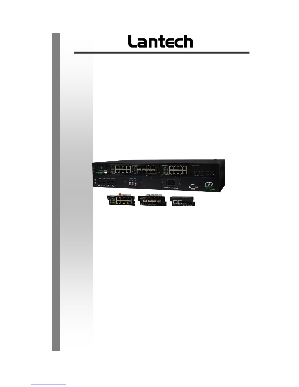
IPGS-6300-2P
IGS-6300-2P
4- Modular-Slots w/4/2 x1G/2.5G/10G SFP+ + 2 10GT uplink L2+
Industrial Managed Ethernet Switch w/ Enhanced G.8032 Ring
User Manual (Hardware)
Oct. 2018
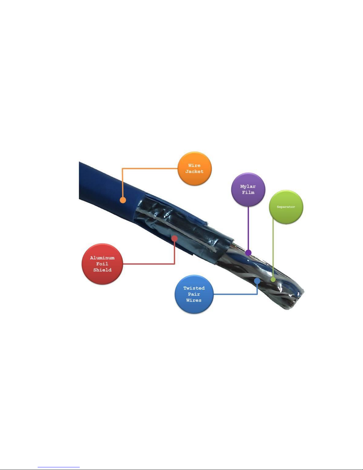
Recommendation for Shielded network cables
STP cables have additional shielding material that is used to reduce external interference.
The shield also reduces the emission at any point in the path of the cable. Our
recommendation is to deploy an STP network cable in demanding electrical environments.
Examples of demanding indoor environments are where the network cable is located in
parallel with electrical mains supply cables or where large inductive loads such as motors
or contactors are in close vicinity to the camera or its cable. It is also mandatory to use an
STP cable where the power device (like IP camera) is used outdoors or where the network
cable is routed outdoors.

Important Notice
Lantech Communications Global, Inc. reserves the right to modify the
equipment, its specification or this manual without prior notice, in the interest
of improving performance, reliability, or servicing. At the time of publication
all data is correct for the operation of the equipment at the voltage and/or
temperature referred to. Performance data indicates typical values related to
the particular product.
No part of this documentation or information supplied may be divulged to any
third party without the express written consent of Lantech Communications
Global Inc. Products offered may contain software which is proprietary to
Lantech Communications Global Inc. The offer or supply of these products
and services does not include or infer any transfer of ownership.
Interference Issues
This Equipment has been tested and found to comply with the limits for a
Class A digital device, pursuant to Part 15 of the FCC rules. These limits are
designed to provide reasonable protection against harmful interference in a
commercial or industrial installation. This equipment generates, uses, and
can radiate radio frequency energy. It may cause harmful interference to
radio communications if the equipment is not installed and used in
accordance with the instructions.

FCC Warning
This Equipment has been tested and found to comply with the limits for a
Class-A digital device, pursuant to Part 15 of the FCC rules. These limits
are designed to provide reasonable protection against harmful interference
in a residential installation. This equipment generates, uses, and can
radiate radio frequency energy. It may cause harmful interference to radio
communications if the equipment is not installed and used in accordance
with the instructions. However, there is no guarantee that interference will
not occur in a particular installation. If this equipment does cause harmful
interference to radio or television reception, which can be determined by
turning the equipment off and on, the user is encouraged to try to correct
the interference by one or more of the following measures:
Reorient or relocate the receiving antenna.
Increase the separation between the equipment and receiver.
Connect the equipment into an outlet on a circuit different from that to
which the receiver is connected.
Consult the dealer or an experienced radio/TV technician for help.
CE Mark Warning
This is a Class-A product. In a domestic environment this product may
cause radio interference in which case the user may be required to take
adequate measures.

Content
Chapter 1 Introduction ........................................... 5
Chapter 2 Hardware Description............................ 5
2.1 Physical Dimension ....................................... 5
2.2 IP Protection ................................................. 7
2.3 LED Indicators .............................................10
Chapter 3 Hardware Installation .......................... 11
Hardware installation .............................................11
3.1 Rack Mounting .............................................12
3.2 Wiring the Power Inputs ...............................14
3.3 Wiring the Fault Alarm Contact ....................17
3.4 Cabling ........................................................18
3.5 USB Dongle ................................ .................21
Chapter 4 Network Application ............................ 22
ITU G.8032 Scheme ..............................................22
Ring Coupling ..........................................................22
Multiple Rings..........................................................23
Dual Homing ...........................................................24
Chain ......................................................................24
Chapter 5 Console Management.......................... 26
5.1 Connecting to the Console Port....................26
5.2 Login in the Console Interface ......................27

5
Chapter 1 Introduction
Lantech I(P)GS-6300-2P is a high performance L2+ (All Gigabit) modular Ethernet
switch with max 24/26port Gigabit + 4/2 1G/2.5G/10G SFP+ + 2 10GT uplink (total
28ports) w/(24 PoE 802.3af/at Injectors) which provides L2+ wire speed and advanced
security function for network aggregation deployment. It delivers ITU G.8032 enhanced
ring recovery less than 20ms in single ring.
Chapter 2 Hardware Description
In this paragraph, it will describe the Industrial switch’s hardware spec, port, cabling
information, and wiring installation.
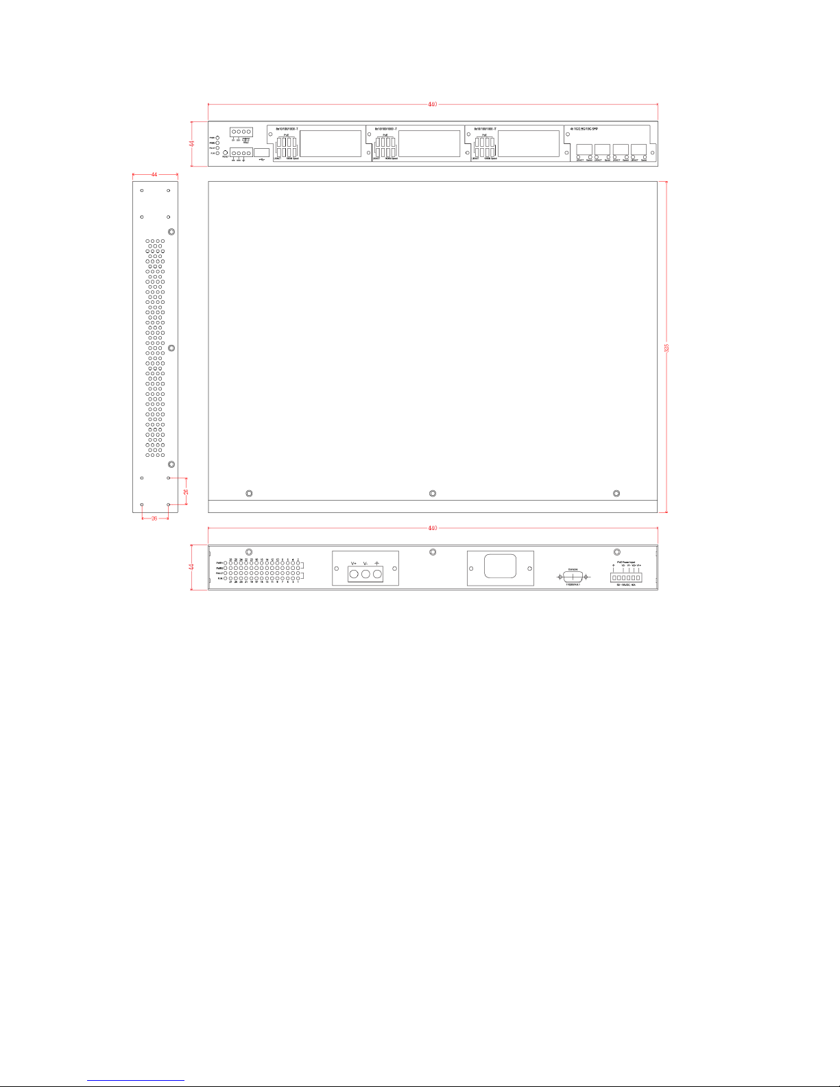
2.1 Physical Dimension
Metal case. IP-30,
440(W) x 325 (D) x 44 (H) mm
6

7
2.2 IP Protection
The IP Code, Ingress Protection Rating, sometimes also interpreted as International
Protection Rating, classifies and rates the degree of protection provided against the
intrusion (including body parts such as hands and fingers), dust, accidental contact, and
water in mechanical casings and with electrical enclosures. It is published by the
International Electrotechnical Commission (IEC)
Solid particle protection
The first digit indicates the level of protection that the enclosure provides against access
to hazardous parts (e.g., electrical conductors, moving parts) and the ingress of solid
foreign objects.
Level
Object size
protected against
Effective against
0
—
No protection against contact and ingress of objects
1
>50 mm
Any large surface of the body, such as the back of a
hand, but no protection against deliberate contact
with a body part
2
>12.5 mm
Fingers or similar objects
3
>2.5 mm
Tools, thick wires, etc.
4
>1 mm
Most wires, screws, etc.
5
Dust protected
Ingress of dust is not entirely prevented, but it must
not enter in sufficient quantity to interfere with the
satisfactory operation of the equipment; complete
protection against contact
6
Dust tight
No ingress of dust; complete protection against
contact

8
Liquid ingress protection
The second digit indicates the level of protection that the enclosure provides against
harmful ingress of water.
Level
Protected
against
Testing for
Details
0
Not
protected
—
—
1
Dripping
water
Dripping water (vertically
falling drops) shall have no
harmful effect.
Test duration: 10 minutes
Water equivalent to 1 mm
rainfall per minute
2
Dripping
water when
tilted up to
15°
Vertically dripping water
shall have no harmful effect
when the enclosure is tilted
at an angle up to 15° from
its normal position.
Test duration: 10 minutes
Water equivalent to 3 mm
rainfall per minute
3
Spraying
water
Water falling as a spray at
any angle up to 60° from
the vertical shall have no
harmful effect.
Test duration: 5 minutes
Water volume: 0.7 litres per
minute
Pressure: 80–100 kPa
4
Splashing
of water
Water splashing against
the enclosure from any
direction shall have no
harmful effect.
Test duration: 5 minutes
Water volume: 10 litres per
minute
Pressure: 80–100 kPa
5
Water jets
Water projected by a
nozzle (6.3 mm) against
enclosure from any
direction shall have no
harmful effects.
Test duration: at least
15 minutes
Water volume: 12.5 litres per
minute
Pressure: 30 kPa at distance
of 3 m
6
Powerful
Water projected in powerful
Test duration: at least
 Loading...