

Lantech IPES-5416DFT, IES-5416DFT User Manual

IPES/IES-5416DFT Series
16 10/100TX + 2 1000T + 2 100/1000FX Dual Speed Fiber L2+ 8 PoE
at/af Industrial Managed Switch w/ITU G.8032 Ring
User Manual (Hardware)
IP-67
IP-43
Sep. 2015
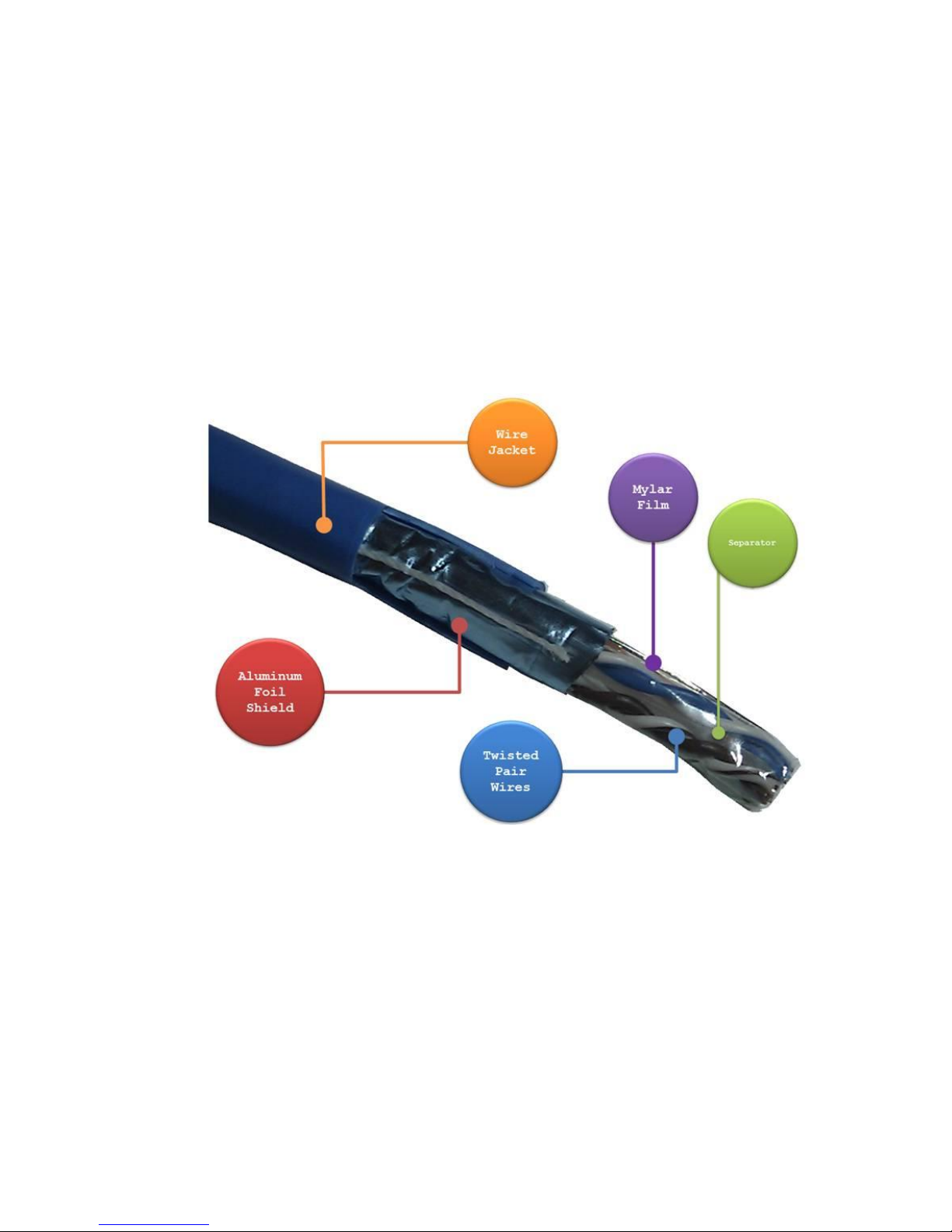
Recommendation for Shielded network cables
STP cables have additional shielding material that is used to reduce external interference.
The shield also reduces the emission at any point in the path of the cable. Our
recommendation is to deploy an STP network cable in demanding electrical environments.
Examples of demanding indoor environments are where the network cable is located in
parallel with electrical mains supply cables or where large inductive loads such as motors
or contactors are in close vicinity to the camera or its cable. It is also mandatory to use an
STP cable where the power device (like IP camera) is used outdoors or where the network
cable is routed outdoors.

Important Notice
Lantech Communications Global, Inc. reserves the right to modify the
equipment, its specification or this manual without prior notice, in the interest
of improving performance, reliability, or servicing. At the time of publication
all data is correct for the operation of the equipment at the voltage and/or
temperature referred to. Performance data indicates typical values related to
the particular product.
No part of this documentation or information supplied may be divulged to any
third party without the express written consent of Lantech Communications
Global Inc. Products offered may contain software which is proprietary to
Lantech Communications Global Inc. The offer or supply of these products
and services does not include or infer any transfer of ownership.
Interference Issues
This Equipment has been tested and found to comply with the limits for a
Class A digital device, pursuant to Part 15 of the FCC rules. These limits are
designed to provide reasonable protection against harmful interference in a
commercial or industrial installation. This equipment generates, uses, and
can radiate radio frequency energy. It may cause harmful interference to
radio communications if the equipment is not installed and used in
accordance with the instructions.

FCC Warning
This Equipment has been tested and found to comply with the limits for a
Class-A digital device, pursuant to Part 15 of the FCC rules. These limits
are designed to provide reasonable protection against harmful interference
in a residential installation. This equipment generates, uses, and can
radiate radio frequency energy. It may cause harmful interference to radio
communications if the equipment is not installed and used in accordance
with the instructions. However, there is no guarantee that interference will
not occur in a particular installation. If this equipment does cause harmful
interference to radio or television reception, which can be determined by
turning the equipment off and on, the user is encouraged to try to correct
the interference by one or more of the following measures:
Reorient or relocate the receiving antenna.
Increase the separation between the equipment and receiver.
Connect the equipment into an outlet on a circuit different from that to
which the receiver is connected.
Consult the dealer or an experienced radio/TV technician for help.
CE Mark Warning
This is a Class-A product. In a domestic environment this product may
cause radio interference in which case the user may be required to take
adequate measures.

Content
Chapter 1 Introduction ............................................. 5
Specification ............................................................. 5
Chapter 2 Hardware Description .......................... 12
2.1 Physical Dimension ...................................... 12
2.2 IP Protection ................................................. 14
2.3 LED Indicators.............................................. 17
Chapter 3 Hardware Installation ........................... 19
Chapter 4 Network Application ............................. 25
4.1 ITU G.8032 Scheme ...................................... 25
4.2 Ring Coupling ................................................ 25
4.3 Multiple Rings ................................................ 26
4.4 Dual Homing .................................................. 27
4.5 Chain ............................................................. 27
Chapter 5 Console Management .......................... 29
5.1 Connecting to the Console Port ................... 29
5.2 Login in the Console Interface ..................... 29

5
Chapter 1 Introduction
Lantech IES-5416DFT & IPES-5416DFT-8(IP67/IP43) series is a high performance L2+
IP67/IP43 industrial Gigabit uplink switch with 8x10/100TX + 2 GigaT + 2Dual Speed
Giga FX w/8 PoE at/af injectors by M12 connectors which provides L2 wire speed and
advanced security function for connecting PD network.
Specification
IES-5416DFT series
Standards
IEEE 802.3 10Base-T Ethernet
IEEE 802.3u 100Base-TX
IEEE802.3z Gigabit fiber
IEEE802.3x Flow Control and Back Pressure
IEEE802.3ad Port trunk with LACP
IEEE802.1d Spanning Tree
IEEE802.1w Rapid Spanning Tree
IEEE802.1s Multiple Spanning Tree
IEEE 802.3ad Link Aggregation Control Protocol (LACP)
IEEE 802.1AB Link Layer Discovery Protocol (LLDP)
IEEE 802.1X User Authentication (Radius)
IEEE802.1p Class of Service
IEEE802.1Q VLAN Tag
Switch
Architecture
Back-plane (Switching Fabric): 11.2Gbps
Packet throughput ability (Full-Duplex): 23.8Mpps @64bytes
Transfer Rate
14,880pps for Ethernet port
148,800pps for Fast Ethernet port
1,488,000pps for Gigabit Fiber Ethernet port
CPU
Marvell 800Mhz
RAM
256M Byte
Flash
128M Byte
Mac Address
16K MAC address table

6
Jumbo frame
10KB on all ports
Connectors
10/100TX: 16 x ports M12 4-pole D-coded with Auto MDI/MDI-X
function
10/100/1000T: 2 x ports M12 8-pole A-coded with Auto MDI/MDIX function
100/1000 Dual Speed Fiber: 2 x LC connector for single-mode or
multi-mode type fiber cable
RS-232 connector: 1 x M12 5-pole A-coded
Power Input connector : 1 x M12 5-pole A-coded
Relay contact : 1 x M12 5-pole A-coded
Network Cable
10Base-T: 2-pair UTP/STP Cat. 3, 4, 5/ 5E/ 6 cable
EIA/TIA-568 100-ohm (100m)
100Base-TX: 2-pair UTP/STP Cat. 5/ 5E/ 6 cable
EIA/TIA-568 100-ohm (100m)
1000Base-TX: 2-pair UTP/STP Cat. 5/ 5E/ 6 cable
EIA/TIA-568 100-ohm (100m)
Giga Optical
Cable
Multi-mode: 50/125um~62.5/125um
Single mode: 9/125um
Available distance: 0.5km (Multi-mode)/10km (Single-mode)
Wavelength: 850nm (Multi-mode)/1310nm (Single-mode)
100M Optical
Cable
Multi-mode: 50/125um~62.5/125um
Single mode: 9/125um
Available distance: 2km (Multi-mode)/30km (Single-mode)
Wavelength: 850nm (Multi-mode)/1310nm (Single-mode)
Bypass
Protection**
High-speed optical switching (<4ms)
Minimal insertion loss (Max 1.6dB as Bypass Mode)
Protocol
CSMA/CD
LED
Per unit: Power 1 (Green), Power 2 (Green), P-Fail (Red)
Ethernet port: Link/Activity (Green), Speed (Green); Optical fiber:
Link/Activity (Green)
DI/DO
1 Digital Input (DI) :
Level 0: -30~2V / Level 1: 10~30V
Max. input current:8mA

7
1 Digital Output(DO): Open collector to 40 VDC, 200mA
Operating
Humidity
5% ~ 95% (Non-condensing)
Operating
Temperature
-40°C~75°C / -40°F~167°F
(72V model: -40°C~60°C / -40°F~140°F)
Storage
Temperature
-40°C~85°C / -40°F~185°F
Power Supply
Standard model:9.5~60VDC dual input
72V model: 50.4~90VDC dual input
110V model : 43~137.5VDC dual input
Power
Consumption
Max. 13W 12V~48VDC input
Max. 16W 72VDC/110VDC input
Case
Dimension
IP67 model: Aluminum case
285mm(W)x200mm(H)x84.4mm(D)
IP43 model: Aluminum case
273mm(W)x187mm(H)x84.4mm(D)
Weight
2.1kgs(IP67); 1.8kgs (IP43)
Installation
DIN Rail** and Wall Mount Design
EMI & EMS
FCC Class A,
CE EN55022 Class A, CE EN55024, CE EN61000-4-2, CE
EN61000-4-3, CE EN61000-4-4, CE EN61000-4-5, CE EN610004-6, CE N61000-4-8, EN61000-4-11
Stability Testing
IEC60068-2-32 (Free fall), EN61373 (Shock and Vibration)
MTBF
NA
Verifications&
report
EN50155/EN50121-3-2/EN50121-4 verification
EN45545-2 R24 (EN ISO 4589-2, EN ISO 5659-2, NF X70-100-1
& 2) Fire & Smoke verification
Warranty
5 years
*Future release
**Optional
8
IPES-5416DFT-8 series
Standards
IEEE 802.3 10Base-T Ethernet
IEEE 802.3u 100Base-TX
IEEE802.3z Gigabit fiber
IEEE802.3x Flow Control and Back Pressure
IEEE802.3ad Port trunk with LACP
IEEE802.1d Spanning Tree
IEEE802.1w Rapid Spanning Tree
IEEE802.1s Multiple Spanning Tree
IEEE 802.3ad Link Aggregation Control Protocol (LACP)
IEEE 802.1AB Link Layer Discovery Protocol (LLDP)
IEEE 802.1X User Authentication (Radius)
IEEE802.1p Class of Service
IEEE802.1Q VLAN Tag
IEEE802.3at/af Power over Ethernet
Switch
Architecture
Back-plane (Switching Fabric): 11.2Gbps
Packet throughput ability (Full-Duplex): 23.8Mpps @64bytes
Transfer Rate
14,880pps for Ethernet port
148,800pps for Fast Ethernet port
1,488,000pps for Gigabit Fiber Ethernet port
CPU
Marvell 800Mhz
RAM
256M Byte
Flash
128M Byte
Mac Address
16K MAC address table
Jumbo frame
10KB on all ports
Connectors
10/100TX: 16 x ports M12 4-pole D-coded with Auto MDI/MDI-X
function
10/100/1000T: 2 x ports M12 8-pole A-coded with Auto MDI/MDIX function
100/1000 Dual Speed Fiber: 2 x LC connector for single-mode or
multi-mode type fiber cable
RS-232 connector: 1 x M12 5-pole A-coded
Power Input connector : 1 x M23 5-pole A-coded

9
Relay contact : 1 x M12 5-pole A-coded
Network Cable
10Base-T: 2-pair UTP/STP Cat. 3, 4, 5/ 5E/ 6 cable
EIA/TIA-568 100-ohm (100m)
100Base-TX: 2-pair UTP/STP Cat. 5/ 5E/ 6 cable
EIA/TIA-568 100-ohm (100m)
1000Base-TX: 2-pair UTP/STP Cat. 5/ 5E/ 6 cable
EIA/TIA-568 100-ohm (100m)
Giga Optical
Cable
Multi-mode: 50/125um~62.5/125um
Single mode: 9/125um
Available distance: 0.5km (Multi-mode)/10km (Single-mode)
Wavelength: 1310nm (Multi-mode/Single-mode)
100M Optical
Cable
Multi-mode: 50/125um~62.5/125um
Single mode: 9/125um
Available distance: 2km (Multi-mode)/30km (Single-mode)
Wavelength: 1310nm (Multi-mode/Single-mode)
Bypass
Protection**
High-speed optical switching (<4ms)
Minimal insertion loss (Max 1.6dB as Bypass Mode)
Protocol
CSMA/CD
LED
Per unit: Power 1 (Green), Power 2 (Green), P-Fail (Red)
Ethernet port: Link/Activity (Green), Speed (Green); Optical fiber:
Link/Activity (Green)
DI/DO
1 Digital Input (DI) :
Level 0: -30~2V / Level 1: 10~30V
Max. input current:8mA
1 Digital Output(DO): Open collector to 40 VDC, 200mA
Operating
Humidity
5% ~ 95% (Non-condensing)
Operating
Temperature
-40°C~75°C / -40°F~167°F
(72V model: -40°C~60°C / -40°F~140°F)
Storage
Temperature
-40°C~85°C / -40°F~185°F
Power Supply
Standard model: 45~56VDC dual input
12V model: 9.5~56VDC dual input
 Loading...