

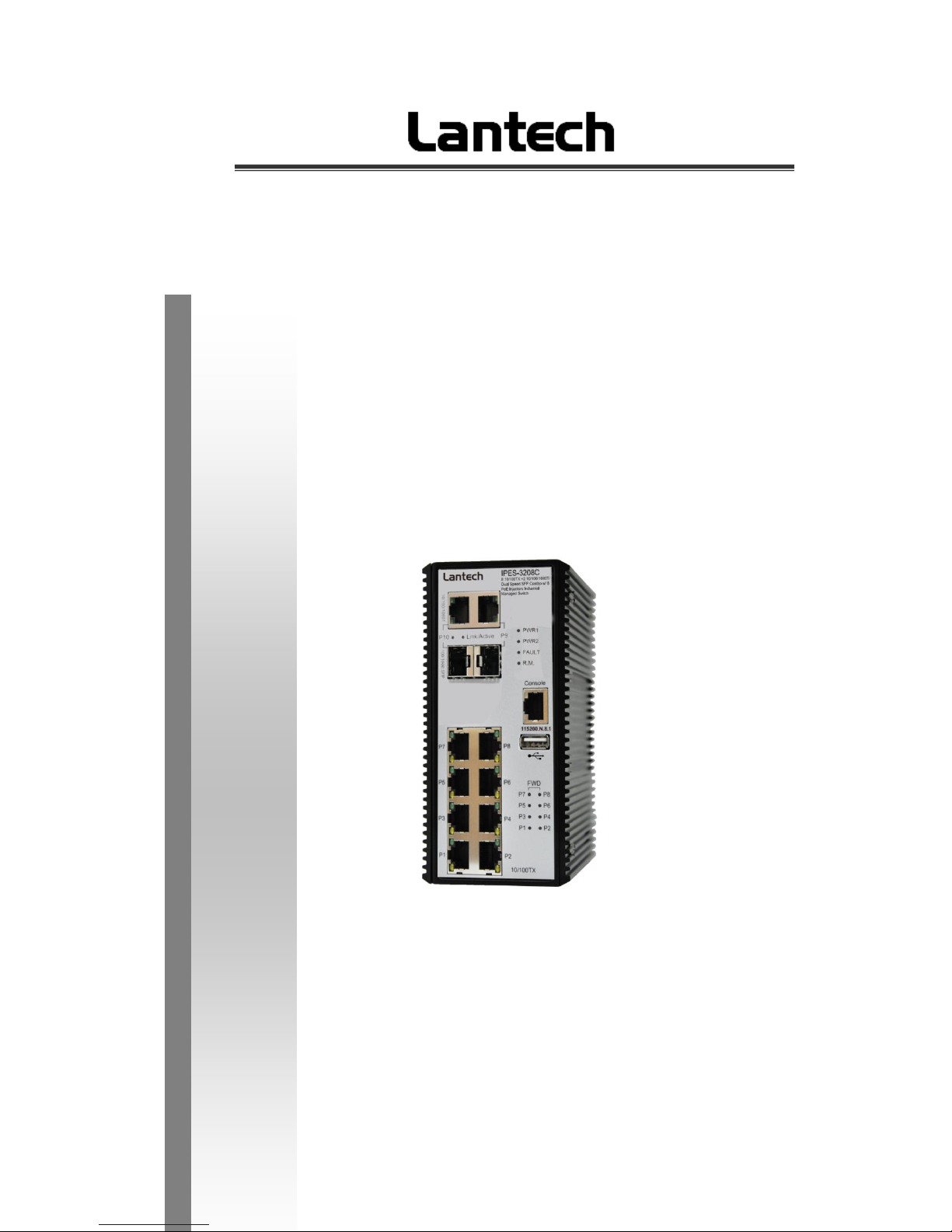
IES-3208C/3307C
IPES-3208C/3307C
IPES-3208CB/3307CB
8 (7)10/100Tx + 2(3) 10/100/1000T/Dual Speed SFP Combo and (8/7
PoE at/af) (Mode A/Mode B)Industrial Managed Switch w/ITU
G.8032 Ring
User Manual
Mar. 2014

Important Notice
Lantech Communications Global, Inc. reserves the right to modify the
equipment, its specification or this manual without prior notice, in the interest
of improving performance, reliability, or servicing. At the time of publication
all data is correct for the operation of the equipment at the voltage and/or
temperature referred to. Performance data indicates typical values related to
the particular product.
No part of this documentation or information supplied may be divulged to any
third party without the express written consent of Lantech Communications
Global Inc. Products offered may contain software which is proprietary to
Lantech Communications Global Inc. The offer or supply of these products
and services does not include or infer any transfer of ownership.
Interference Issues
This Equipment has been tested and found to comply with the limits for a
Class A digital device, pursuant to Part 15 of the FCC rules. These limits are
designed to provide reasonable protection against harmful interference in a
commercial or industrial installation. This equipment generates, uses, and
can radiate radio frequency energy. It may cause harmful interference to
radio communications if the equipment is not installed and used in
accordance with the instructions.

FCC Warning
This Equipment has been tested and found to comply with the limits for a
Class-A digital device, pursuant to Part 15 of the FCC rules. These limits
are designed to provide reasonable protection against harmful interference
in a residential installation. This equipment generates, uses, and can
radiate radio frequency energy. It may cause harmful interference to radio
communications if the equipment is not installed and used in accordance
with the instructions. However, there is no guarantee that interference will
not occur in a particular installation. If this equipment does cause harmful
interference to radio or television reception, which can be determined by
turning the equipment off and on, the user is encouraged to try to correct
the interference by one or more of the following measures:
Reorient or relocate the receiving antenna.
Increase the separation between the equipment and receiver.
Connect the equipment into an outlet on a circuit different from that to
which the receiver is connected.
Consult the dealer or an experienced radio/TV technician for help.
CE Mark Warning
This is a Class-A product. In a domestic environment this product may
cause radio interference in which case the user may be required to take
adequate measures.

Content
Chapter 1 Introduction ........................................... 1
Hardware Features ................................................. 1
Software Features .................................................. 3
Chapter 2 Hardware Description............................ 8
2.1 Physical Dimension ....................................... 8
2.2 IP Protection ................................................10
2.3 LED Indicators .............................................13
Chapter 3 Hardware Installation .......................... 14
3.1Hardware installation ........................................14
3.2 DIN-Rail Mounting ........................................15
3.3 Wall Mount Plate Mounting ..........................17
3.4 Wiring the Power Inputs ...............................18
3.5 Wiring the Fault Alarm Contact ....................19
3.6 Cabling ........................................................20
Chapter 4 Network Application ............................ 23
ITU G.8032 Scheme ..............................................23
Ring Coupling ..........................................................23
Multiple Rings..........................................................24
Dual Homing ...........................................................25
Chain ......................................................................25
Chapter 5 Console Management.......................... 27
5.1 Connecting to the Console Port....................27
5.2 Login in the Console Interface ......................28
Chapter 6 Web-Based Management .................... 29

6.1 About Web-based Management ................... 29
6.2 Preparing for Web Management ..................29
6.3 System Login ...............................................30
6.4 System .........................................................31
6.4.1 System Identification Configuration ...................... 31
6.4.2 Switch Information ................................................ 32
6.4.3 IP configuration ..................................................... 32
6.4.4 DHCP server ......................................................... 34
6.4.5 System Time ................................................... 35
6.4.6 SNMP Configuration .......................................... 39
6.4.7 Fault Relay Configuration .................................. 40
6.4.8 Digital Input/Output ....................................... 42
6.5 Event & Log ................................................44
6.5.1 View Logs ............................................................. 44
6.5.2 Events ................................................................... 45
6.5.3 DDM event ............................................................ 46
6.5.4 Actions .................................................................. 47
6.5.5 Event Action Map ................................................. 50
6.6 Ports ................................................................52
6.6.1 Device Settings ..................................................... 52
6.6.2 Status ................................................................. 53
6.6.3 Statistics ............................................................... 53
6.6.4 Mirroring ................................................................ 54
6.6.5 Rate Limiting ......................................................... 55
6.6.6 Loop Protection..................................................... 56
6.7 Power over Ethernet (IPES series) ..................57
6.7.1 Configuration(PoE Mode A) ................................. 58
6.7.2 Status .................................................................... 59

6.7.3 Detection ............................................................... 61
6.7.4 Scheduling ............................................................ 63
6.7.5 Configuration(PoE Mode B) ................................. 64
6.7.6 Configuration(PoE Mode B) ................................. 65
6.7.7 Detection(Mode B) ................................................ 65
6.7.8 Scheduling(Mode B) ............................................. 67
6.8 Topology ..........................................................68
6.9 QoS .................................................................71
6.9.1 QoS Policy ............................................................ 71
6.10 Security .........................................................73
6.10.1 MAC Address Tables .......................................... 73
6.10.2 Access Control List ............................................. 74
6.10.3 IEEE 802.1X Radius Server ............................... 75
6.10.4 IP Security .......................................................... 76
6.11 VLAN .............................................................77
6.11.1 802.1Q VLAN Config .......................................... 77
6.11.2 Status .................................................................. 79
6.12 MVR ..............................................................80
6.12 LLDP .............................................................81
6.12.1 LLDP Configuration ............................................ 81
6.12.2 LLDP Neighbor ................................................... 82
6.12.3 LLDP Statistics ................................................... 84
6.13 CDP ...............................................................87
6.13.1 CDP Configuration Device Settings ................... 87
6.13.2 CDP Port Configuration ...................................... 88
6.13.3. CDP Status ........................................................ 88
6.14 IGMP Snooping .............................................90
6.14.1 IGMP Snooping Configuration ............................ 91

6.14.2 IGMP Snooping Status ....................................... 92
6.15 MSTP ............................................................94
6.15.1. MSTP Global Configuration .......................94
6.15.2 How to enable MSTP .......................................... 95
6.15.3 CIST Settings...................................................... 97
6.15.3.1 Bridge configuration .......................... 97
6.15.3.2 Port .................................................... 97
6.15.4. MSTP MSTI Settings ......................................... 98
6.15.5. MSTP Bridges Status ........................................ 99
6.15.6. Bridge status of all ports .................................. 100
6.16 Aggregation .............................................. 101
6.16.1. Aggregation Configuration ............................... 101
6.16.2 LACP Port Status ............................................. 102
6.17 G.8032 ERPS .............................................. 104
6.17.1. G.8032 Ethernet Ring Protection Configuration105
6.17.2 How to set ERPS G.8032 ................................. 106
6.18 Dual Homing ............................................. 108
6.19 Maintenance ................................ ................ 110
6.19.1 Save Configuration ........................................... 110
6.19.2 Config backup/restore ................................ 110
6.19.3 Restart device ................................................... 111
6.19.4 Firmware Upgrade ............................................ 112
6.19.5 Diagnostics ....................................................... 112
Appendix —Command Line mode ...................... 116

1
Chapter 1 Introduction
Lantech IES-3208/3307 series(include PoE series) are high performance L2+ industrial
8 (7)10/100Tx + 2(3) 10/100/1000T/Dual Speed SFP Combo (with 7/8 PoE at/af
injectors- IPES series) which provides L2 wire speed and advanced security function for
connecting PD network. They delivers ITU G.8032 ring recovery less than 20ms,
comprehensive QoS, , IGMPv1/v2/v3 & IGMP routing port, MVR (multicast VLAN
registration) , LACP link aggregation and advanced security including ACL, TACAS+*,
SSH/SSL, DHCP Option 82*which are important features required in large network. It
also supports Cisco Discovery Protocol (CDP) and LLDP for Ciscoworks to detect the
switch info to be shown on L2 map topology. The user friendly UI, innovative auto
topology drawing and topology demo makes Lantech Full gigabit series much easier to
get hands-on.
Hardware Features
Standard
IEEE 802.3 10Base-T Ethernet
IEEE 802.3u 100Base-TX
IEEE802.3z Gigabit fiber
IEEE802.3x Flow Control and Back Pressure
IEEE802.3ad Port trunk with LACP
IEEE802.1d Spanning Tree
IEEE802.1w Rapid Spanning Tree
IEEE802.1s Multiple Spanning Tree
IEEE 802.3ad Link Aggregation Control Protocol (LACP)
IEEE 802.1AB Link Layer Discovery Protocol (LLDP)
IEEE 802.1X User Authentication (Radius)
IEEE802.1p Class of Service
IEEE802.1Q VLAN Tag
IEEE802.3at/af Power over Ethernet
Switch
Architecture
Back-plane (Switching Fabric): 5.6(3208)/7.4Gbps(3307)

2
Transfer Rate
14,880pps for Ethernet port
148,800pps for Fast Ethernet port
1,488,000pps for Gigabit Ethernet port
MAC Address
16K MAC address table
Connector
10/100Tx: 8(7) x RJ-45 type connector(2/3 will reserve for
combo SFP port)
Dual Speed SFP Combo: 2(3) x 1000 SFP Sockets
Power & P-Fail connector: 1 x 6-pole terminal block
Digital Input/Output: 1 x 6-pole terminal block
RS-232 connector: 1 x RJ-45 type connector
USB slot for backup and restore
Network Cable
10/100Tx: 2-pair UTP/STP Cat. 5/ 5E / 6 cable
EIA/TIA-568 100-ohm (100m)
Protocol
CSMA/CD
LED
Per unit: Power 1 (Green), Power 2 (Green), FAULT (Red)
Ethernet port: Link/Activity (Green), 100Tx (Green); Giga-T:
Link/Activity (Green)
PoE FWD(IPES): Green( Mode A), Yellow(Mode B)
DI/DO
1 Digital Input(DI):
Level 0: -30~2V/Level1: 10~30V
Max. input current:8mA
1 Digital Output(DO): open collector to 40VDC, 200mA
Power Supply
48 VDC for 802.3af(IPES series)
54VDC for 802.3at(IPES series)
24~48VDC (IES series)
Power
Consumption
Max 9W for system
PoE Power
Budget
Max. 240W under 48VDC power input (IPES series)
Operating
Humidity
5% to 95% (Non-condensing)

3
Operating
Temperature
-20oC ~ 60oC
-40oC ~ 75oC(Wide Temp series)
Storage
Temperature
-40oC ~ 85oC
Case Dimension
Metal case. IP-30,
74(W) x 114 (D) x 152 (H) mm
Installation
DIN rail and wall mount ear**
EMI
FCC Class A, CE EN61000-4-2, CE EN61000-4-3, CE EN61000-4-4, CE EN61000-4-5,
CE EN61000-4-6, CE EN61000-4-8, CE EN61000-4-11, CE
EN61000-4-12, CE EN61000-6-2, CE EN61000-6-4
Stability Testing
IEC60068-2-32 (Free fall), IEC60068-2-27 (Shock),
IEC60068-2-6 (Vibration)
Software Features
Management
SNMP v1 v2c, v3/ Web/Telnet/CLI
SNMP MIB
RFC 1215 Traps MIB,
RFC 1213 MIBII,
RFC 1157 SNMP MIB,
RFC 1493 Bridge MIB,
RFC 2674 VLAN MIB,
RFC 1643 EtherLike,
RFC 1757 RMON,
RSTP MIB,
Private MIB,
LLDP MIB
ITU G.8032
Support ITU G.8032 v2 for Ring protection in less than
50ms for self-heal recovery < 256 switches ;

4
Support various ring/chain topologies
Ring covers data & multicast* packets
User friendly UI
Auto topology drawing
Topology demo
Auto configuration for G.8032*
Port Trunk with
LACP
LACP Port Trunk: 4 Trunk groups/Maximum 4 trunk
members
Load balancing through LACP to distribute load*
LLDP
Supports LLDP to allow switch to advise its identification
and capability on the LAN
CDP
Cisco Discovery Protocol for topology mapping
PoE
Management
(IPES series)
PoE Detection to check if PD is hang up then restart the
PD
PoE scheduling to On/Off upon routine time table
Per port PoE status include voltage、current and watts
VLAN
Port Based VLAN
IEEE 802.1Q Tag VLAN (256 entries)/ VLAN ID (Up to 4K,
VLAN ID can be assigned from 1 to 4096.)
GVRP (256 Groups)*,GMRP*, MVRP (Multi VLAN
Registration), QinQ*
Network Security
Support 10 IP addresses that have permission to access
the switch management and to prevent unauthorized
intruder.
802.1X access control for port based and MAC based
authentication/MAC-IP-Port binding
Management access control with priority

5
256 Policy based Access Control List
SSL/ SSH for Management
TACACS+ for Authentication*
SMTP/Text SMS
Supports SMTP Server and 6 e-mail accounts for
receiving event alert; can send SMS text alert via mobile
Spanning Tree
Supports IEEE802.1d Spanning Tree and IEEE802.1w
Rapid Spanning Tree, IEEE802.1s Multiple Spanning Tree
Quality of Service
The quality of service determined by port, Tag and IPv4
Type of service, IPv4 Different Service
Class of Service
Supports IEEE802.1p class of service, per port provides 4
priority queues
IP Security
Supports 10 IP addresses that have permission to access
the switch management and to prevent unauthorized
intruder.
Login Security
Supports IEEE802.1X Authentication/RADIUS
Port Mirror
Support 3 mirroring types: “RX, TX and Both packet”
IGMP
Support IGMP snooping v1,v2,v3; Supports IGMP static
route
256 multicast groups and IGMP query
Multicast VLAN
Registration*
MVR enables multicast packets go through VLAN for VOD
application
Bandwidth
Control
Support ingress packet filter and egress packet limit.
The egress rate control supports all of packet type.
Ingress filter packet type combination rules are
Broadcast/Multicast/Flooded Uni-cast packet,
Broadcast/Multicast packet, Broadcast packet only and all

6
types of packet.
The packet filter rate can be set an accurate value through
the pull-down menu for the ingress packet filter and the
egress packet limit.
RTC
Built-in Real Time Clock to keep track of time always
Flow Control
Supports Flow Control for Full-duplex and Back Pressure
for Half-duplex
System Log
Supports System log record and remote system log server
SMTP
Supports SMTP Server and 6 e-mail accounts for receiving
event alert
Relay Alarm
Provides one relay output for port breakdown, power fail
Alarm Relay current carry ability: 1A @ DC24V
SNMP Trap
1. Topology Change
2. Power Trap
3. MAC-Violation
DHCP
Provides DHCP Client/ DHCP Server/ Port and IP Binding
DNS
Provides DNS client feature and supports Primary and
Secondary DNS server
SNTP
Supports SNTP to synchronize system clock in Internet
Firmware Update
Supports TFTP firmware update, TFTP backup and restore.
Configuration
Upload/Download
Supports text configuration file for system quick installation;

7
ifAlias
Each port allows an alphabetic string of 128-byte assigned
as its own unique name via the SNMP or CLI interface
8
Chapter 2 Hardware Description
In this paragraph, it will describe the Industrial switch’s hardware spec, port, cabling
information, and wiring installation.
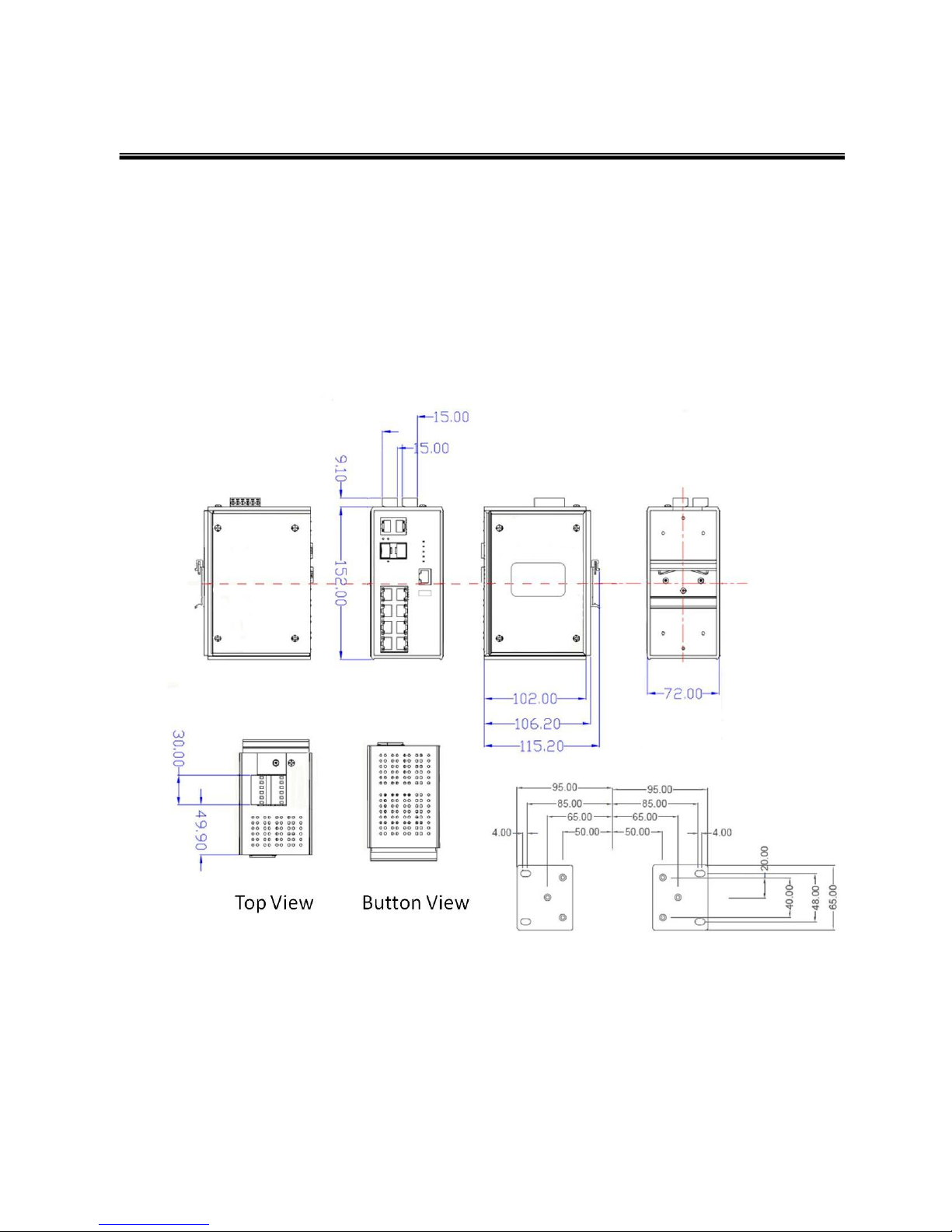
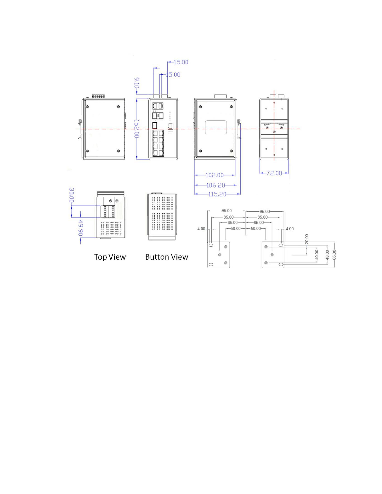
2.1 Physical Dimension
Metal case. IP-30,
74(W) x 105 (D) x 152 (H) mm
9

10
2.2 IP Protection
The IP Code, Ingress Protection Rating, sometimes also interpreted as International
Protection Rating, classifies and rates the degree of protection provided against the
intrusion (including body parts such as hands and fingers), dust, accidental contact, and
water in mechanical casings and with electrical enclosures. It is published by the
International Electrotechnical Commission (IEC)
Solid particle protection
The first digit indicates the level of protection that the enclosure provides against access
to hazardous parts (e.g., electrical conductors, moving parts) and the ingress of solid
foreign objects.
Level
Object size
protected against
Effective against
0
—
No protection against contact and ingress of objects
1
>50 mm
Any large surface of the body, such as the back of a
hand, but no protection against deliberate contact
with a body part
2
>12.5 mm
Fingers or similar objects
3
>2.5 mm
Tools, thick wires, etc.
4
>1 mm
Most wires, screws, etc.
5
Dust protected
Ingress of dust is not entirely prevented, but it must
not enter in sufficient quantity to interfere with the
satisfactory operation of the equipment; complete
protection against contact
6
Dust tight
No ingress of dust; complete protection against
contact

11
Liquid ingress protection
The second digit indicates the level of protection that the enclosure provides against
harmful ingress of water.
Level
Protected
against
Testing for
Details
0
Not
protected
—
—
1
Dripping
water
Dripping water (vertically
falling drops) shall have no
harmful effect.
Test duration: 10 minutes
Water equivalent to 1 mm
rainfall per minute
2
Dripping
water when
tilted up to
15°
Vertically dripping water
shall have no harmful effect
when the enclosure is tilted
at an angle up to 15° from
its normal position.
Test duration: 10 minutes
Water equivalent to 3 mm
rainfall per minute
3
Spraying
water
Water falling as a spray at
any angle up to 60° from
the vertical shall have no
harmful effect.
Test duration: 5 minutes
Water volume: 0.7 litres per
minute
Pressure: 80–100 kPa
4
Splashing
of water
Water splashing against
the enclosure from any
direction shall have no
harmful effect.
Test duration: 5 minutes
Water volume: 10 litres per
minute
Pressure: 80–100 kPa
5
Water jets
Water projected by a
nozzle (6.3 mm) against
enclosure from any
direction shall have no
harmful effects.
Test duration: at least
15 minutes
Water volume: 12.5 litres per
minute
Pressure: 30 kPa at distance
of 3 m
6
Powerful
Water projected in powerful
Test duration: at least

12
water jets
jets (12.5 mm nozzle)
against the enclosure from
any direction shall have no
harmful effects.
3 minutes
Water volume: 100 litres per
minute
Pressure: 100 kPa at
distance of 3 m
7
Immersion
up to 1 m
Ingress of water in harmful
quantity shall not be
possible when the
enclosure is immersed in
water under defined
conditions of pressure and
time (up to 1 m of
submersion).
Test duration: 30 minutes
Immersion at depth of at
least 1 m measured at
bottom of device, and at least
15 cm measured at top of
device
8
Immersion
beyond 1 m
The equipment is suitable
for continuous immersion in
water under conditions
which shall be specified by
the manufacturer.
Normally, this will mean
that the equipment is
hermetically sealed.
However, with certain types
of equipment, it can mean
that water can enter but
only in such a manner that
it produces no harmful
effects.
Test duration: continuous
immersion in water
Depth specified by
manufacturer
9
Powerful
high
temperature
water jets
Protected against closerange high pressure, high
temperature spray downs.
—

13
2.3 LED Indicators
The diagnostic LEDs that provide real-time information of system and optional status are
located on the front panel of the industrial switch. The following table provides the
description of the LED status and their meanings for the switch.
LED
Color
Status
Meaning
R.M
Green
On
The switch unit is owner switch of ITU-Ring
Off
The switch is not owner switch
PWR1
Green
On
Power 1 is active
Off
Power 1 is inactive
PWR2
Green
On
Power 2 is active
Off
Power 2 is inactive
FAULT
Red
On
Power or port failure
Off
No failure
P1 ~ P8
(3208)
P1~P7
(3307)
Link/Ack
On
A network device is detected.
Blinking
The port is transmitting or receiving packets
from the TX device.
Off
No device attached
PoE FWD
Off
The port is not operating in PoE mode.
On
The port is operating in PoE mode.
P9 ~ P10
(3208)
P8~P10
(3307)
8, 9,10,
On
A network device is detected.
Blinking
The port is transmitting or receiving packets
from the TX device.
Off
No device attached.

14
Chapter 3 Hardware Installation
3.1Hardware installation
1. Unpack the Industrial switch
2. Check if the DIN-Rail is screwed on the Industrial switch or not. If the DIN-Rail is not
screwed on the Industrial switch, please refer to DIN-Rail Mounting section for DINRail installation. If users want to wall mount the Industrial switch, please refer to Wall
Mount Plate Mounting section for wall mount plate installation. NOTE: Wall mount
kits are optional accessories.
3. To hang the Industrial switch on the DIN-Rail track or wall.
4. Power on the Industrial switch. Please refer to the Wiring the Power Inputs section
for knowing the information about how to wire the power. The power LED on the
Industrial switch will light up. Please refer to the LED Indicators section for indication
of LED lights.
5. Prepare the twisted-pair, straight through Category 5 cable for Ethernet connection.
6. Insert one side of RJ-45 cable (category 5) into the Industrial switch Ethernet port
(RJ-45 port) and another side of RJ-45 cable (category 5) to the network device’s
Ethernet port (RJ-45 port), ex: Switch PC or Server. The UTP port (RJ-45) LED on
the Industrial switch will light up when the cable is connected with the network device.
Please refer to the LED Indicators section for LED light indication.
[NOTE]
Make sure that the connected network devices support MDI/MDI-X. If it does not
support, use the crossover category-5 cable.
7. When all connections are set and LED lights all show in normal, the installation is
complete.
15
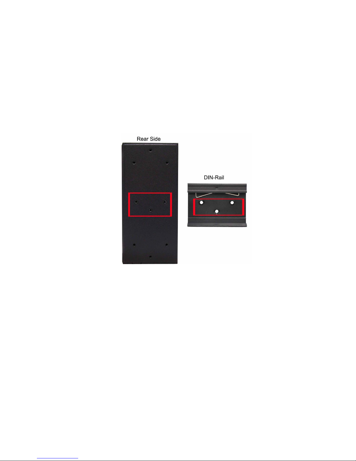
3.2 DIN-Rail Mounting
The DIN-Rail is screwed on the industrial switch when out of factory. If the DIN-Rail is
not screwed on the industrial switch, please see the following pictures to screw the DINRail on the switch. Follow the steps below to hang the industrial switch.
16
1. First, insert the top of DIN-Rail into the track.
2. Then, lightly push the DIN-Rail into the track.
3. Check if the DIN-Rail is tightened on the track or not.
4. To remove the industrial switch from the track, reverse above steps.
17
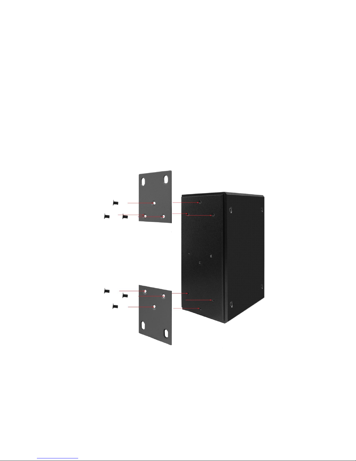
3.3 Wall Mount Plate Mounting
Follow the steps below to mount the industrial switch with wall mount plate.
1. Remove the DIN-Rail from the industrial switch; loose the screws to remove the DINRail.
2. Place the wall mount plate on the rear panel of the industrial switch.
3. Use the screws to screw the wall mount plate on the industrial switch.
4. Use the hook holes at the corners of the wall mount plate to hang the industrial
switch on the wall.
5. To remove the wall mount plate, reverse the above steps.
NOTE : Wall mount kits are optional accessories
18
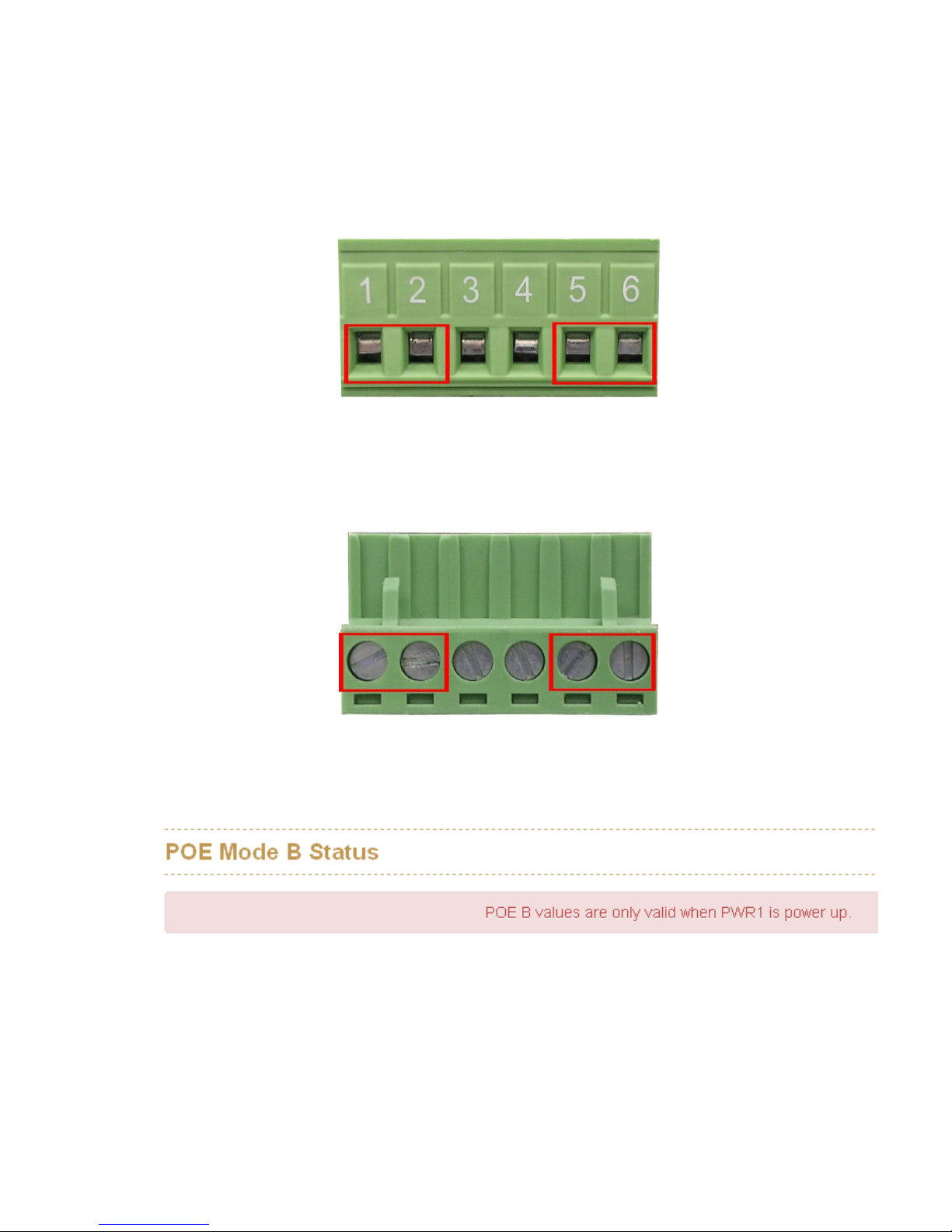
3.4 Wiring the Power Inputs
Please follow the steps below to insert the power wire.
1. Insert AC or DC power wires into the contacts 1 and 2 for power 1, or 5 and 6 for
power.
2. Tighten the wire-clamp screws for preventing the wires from loosing.
3. The PoE Mode B only support Power Input 1(PWR1) , if you only connect PWR2 with
switch, it will show the error message in the GUI of PoE Mode B.
[NOTE]
The wire gauge for the terminal block should be in the range between 12 ~ 24
AWG.
19
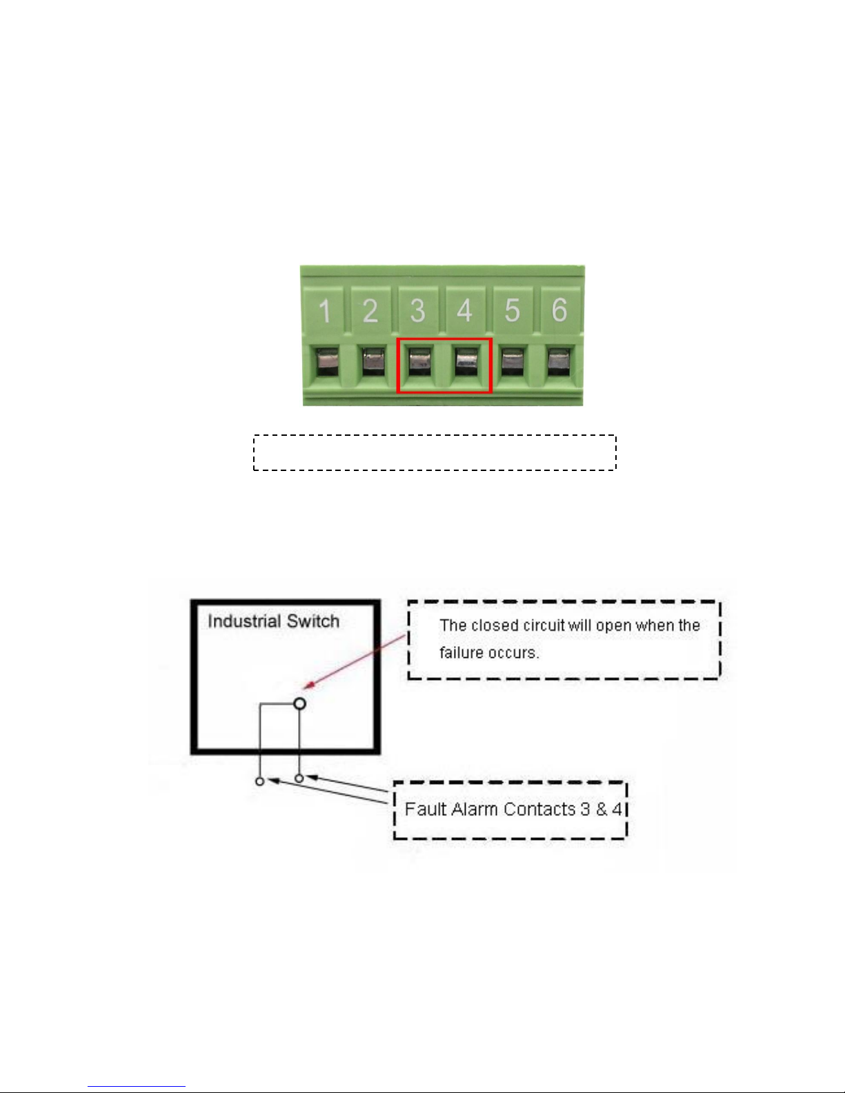
3.5 Wiring the Fault Alarm Contact
The fault alarm contacts are in the middle of the terminal block connector as the picture
shows below. Inserting the wires, the switch will detect the fault status of the power
failure, or port link failure (available for managed model) and then forms an open circuit.
The following illustration shows an application example for wiring the fault alarm contacts.
[NOTE]
The wire gauge for the terminal block should be in the range between 12 ~ 24
AWG.
Insert the wires into the fault alarm contacts
20
3.6 Cabling
Use four twisted-pair, Category 5e or above cabling for RJ-45 port connection. The
cable between the switch and the link partner (switch, hub, workstation, etc.) must
be less than 100 meters (328 ft.) long.
Fiber segment using single-mode connector type must use9/125 µm single-mode
fiber cable. User can connect two devices in the distance up to 30km.
Fiber segment using multi-mode connector type must use 50 or 62.5/125 µm multi-
mode fiber cable. User can connect two devices up to 2kmdistances.
Gigabit / 100M SFP port:
The small form-factor pluggable (SFP) is a compact optical transceiver used in optical
communications for both telecommunication and data communications. The SFP slots
supporting Gigabit speed up to 1000Mbps. –DSFP/-DFT models support dual speed
100M or 1000Mbps. They are used for connecting to the network segment with single
or multi-mode fiber. You can choose the appropriate SFP transceiver to plug into the
slots. Then use proper multi-mode or single-mode fiber according to the transceiver.
With fiber optic, it transmits at speed up to 1000 Mbps or dual speed (-DSFP/-DFT
models) and you can prevent noise interference from the system.
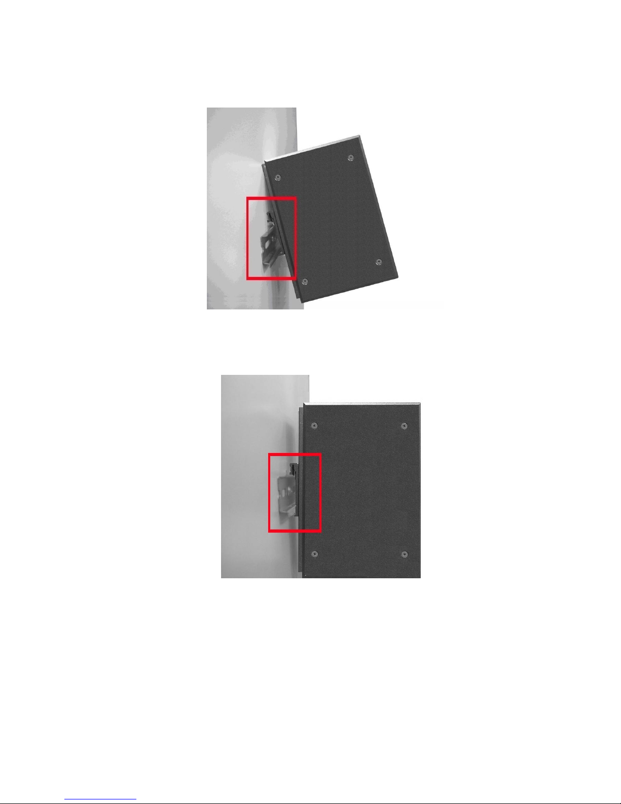
To connect the transceiver and LC cable, please follow the steps shown below:
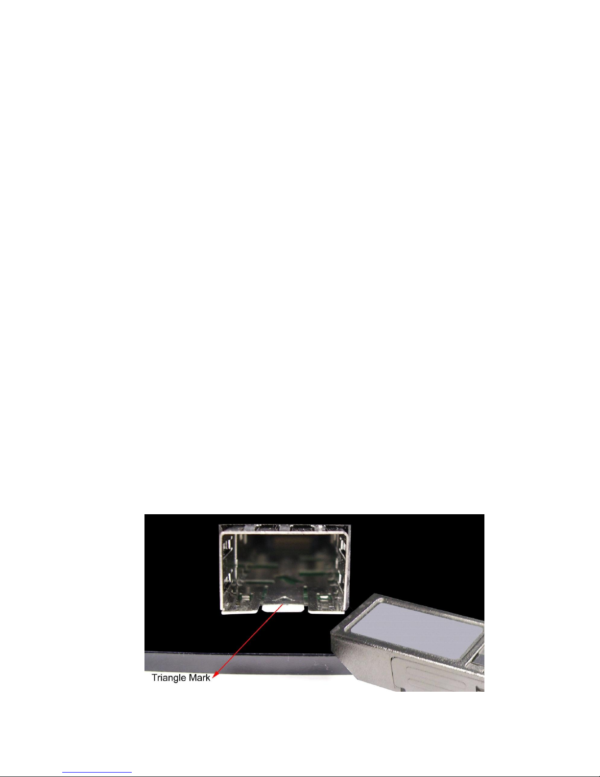
First, insert the transceiver into the SFP module. Notice that the triangle mark is the
bottom of the module.
Transceiver to the SFP module
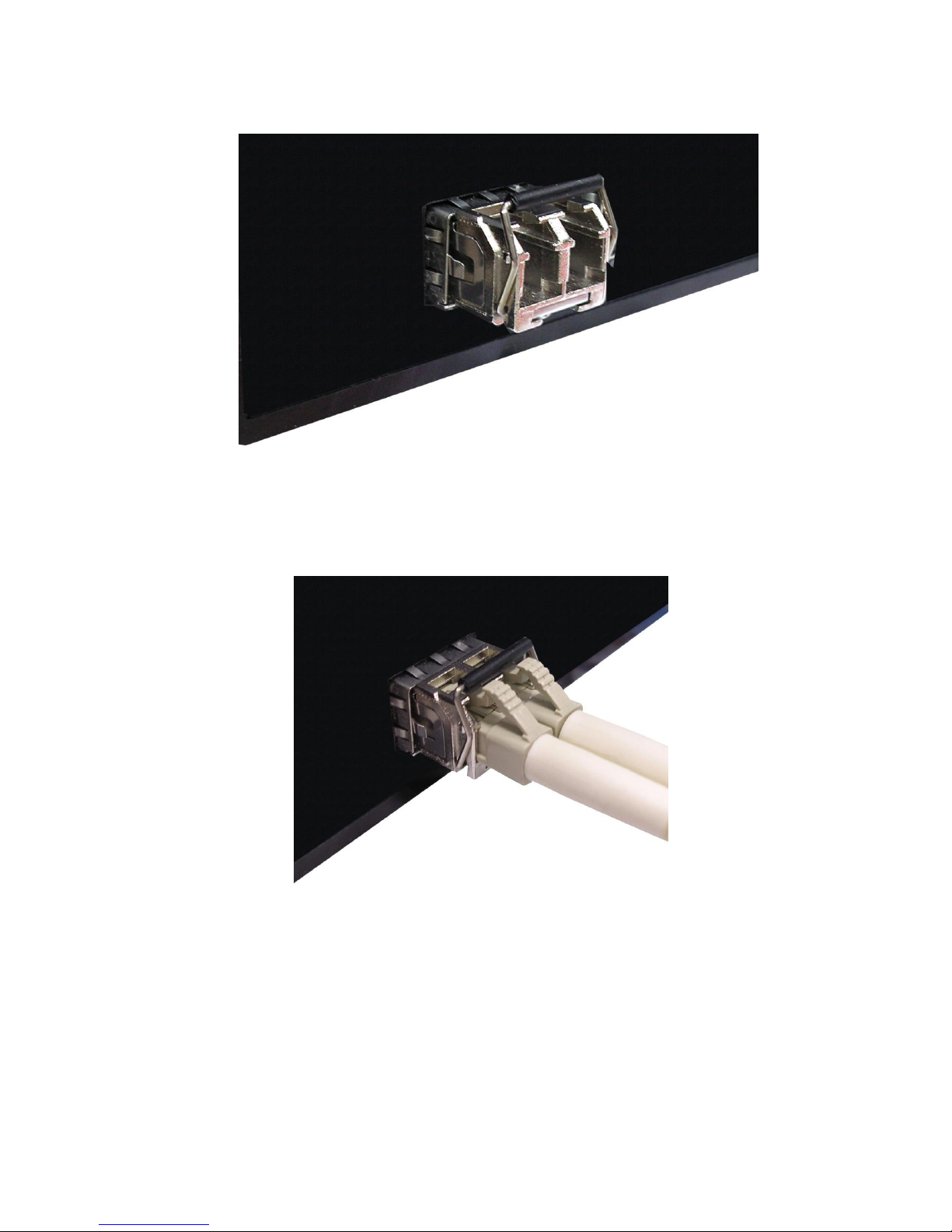
21
Transceiver Inserted
Second, insert the fiber cable of LC connector into the transceiver.
LC connector to the transceiver
22
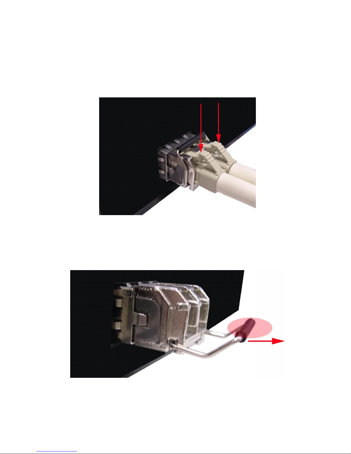
To remove the LC connector from the transceiver, please follow the steps shown below:
First, press the upper side of the LC connector to release from the transceiver and pull it
out.
Remove LC connector
Second, push down the metal loop and pull the transceiver out by the plastic handle.
Pull out from the transceiver
23
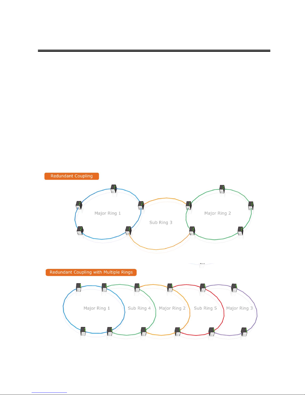
Chapter 4 Network Application
ITU G.8032 Scheme
Lantech G.8032 protocol is following ITU (International Telecommunication Unit) G.8032
v2 draft. The benefits of G.8032 are:
1. <50ms recovery time when failover
2. G.8032 has defined the protocol scheme, parameters, functions, test measures to be
unified that the users can evaluate the possible network infrastructure without literally
testing each brand in large scale.
Ring Coupling
 Loading...