

4 10/100/1000T + 4 10/100/1000T/Dual
Speed SFP L2 Managed Industrial Switch
w/ Pro-Ring
IGS-2404
User Manual

Content
Overview
Introduc
.............................................................1
tion ..............................................................1
Features................................................................... 4
Packing List
Safety Precaution
Hardware Description
Front Panel
Top View
..............................................................6
.....................................................6
.........................................7
...............................................................7
..................................................................8
Wiring the Power Inputs
LED Indicators
Ports
Cabling
.......................................................................10
...................................................................11
..........................................................9
Mounting Installation
DIN-Rail Mounting
Wall Mount Plate Mounting
..................................................15
Hardware Installation
...........................................8
........................................15
....................................16
........................................18

Installation Steps....................................................18
X-Ring Application.................................................. 19
Coupling Ring Application...................................... 20
Dual Homing Application........................................21
Console Management......................................23
Connecting to the Console Port.............................23
Pin Assignment......................................................23
Login in the Console Interface ............................... 24
CLI Management.................................................... 25
Commands Level.............................................................26
Commands Set List..........................................................27
System Commands Set ...................................................27
Port Commands Set.........................................................30
Trunk Commands Set......................................................32
VLAN Commands Set......................................................33
Spanning Tree Commands Set........................................35
QOS Commands Set .......................................................38
IGMP Commands Set......................................................39
Mac / Filter Table Commands Set....................................39
SNMP Commands Set.....................................................40

Port Mirroring Commands Set
802.1x Commands Set
TFTP Commands Set
SystemLog, SMTP and Event Commands Set
SNTP Commands Set
Pro-ring Commands Set
.....................................................43
......................................................45
......................................................48
...................................................49
Web-Based Management
About Web-based Management
Preparing for Web Management
..........................................42
.................................50
............................50
............................50
................46
System Login
Main interface
System Information
.........................................................51
.........................................................52
................................................53
IP Configuration .....................................................53
DHCP Server – System configuration
DHCP Client – System Configuration
DHCP Server - Port and IP Bindings
TFTP - Update Firmware
.......................................56
....................54
....................55
.....................56
TFTP – Restore Configuration
TFTP - Backup Configuration
...............................57
.................................57
System Event Log – Syslog Configuration
.............58

System Event Log - SMTP Configuration .............. 59
System Event Log - Event Configuration...............61
Fault Relay Alarm................................................... 63
SNTP Configuration...............................................63
IP Security.............................................................. 66
User Authentication................................................ 67
Port Statistics.........................................................68
Port Control............................................................ 69
Port Trunk ..............................................................70
Aggregator setting............................................................70
Aggregator Information ....................................................71
State Activity ....................................................................72
Port Mirroring .........................................................73
Rate Limiting..........................................................73
VLAN configuration................................................74
VLAN configuration - Port-based VLAN...........................75
802.1Q VLAN...................................................................78
Rapid Spanning Tree.............................................81
RSTP - System Configuration..........................................81
RSTP - Port Configuration ...............................................82

SNMP Configuration
System Configuration
Trap Configuration
SNMPV3 Configuration
QoS Configuration
QoS Policy and Priority Type
Port Base Priority
COS Configuration
TOS Configuration
.............................................................90
..............................................83
.......................................................84
...........................................................85
....................................................86
..................................................89
...........................................................91
...........................................................91
...........................................89
IGMP Configuration
Pro-Ring System
Security
802.1X/Radius Configuration
MAC Address Table
..................................................................95
Factory Default
....................................................93
.....................................................101
Save Configuration
System Reboot
Troubles shooting
.....................................................101
...........................................102
................................................91
...........................................95
.........................................................98
...............................................101
Technical Specification
...................................103

Overview
Introduction
To create reliab
Managed Industrial Switch comes equipped with a proprietary
redundant network protocol:Pro-Ring provides users with an easy way
to establish a redundant Ethernet network with ultra high-speed
recovery time less than 10 ms. Also, the long MTBF (Mean Time
Between Failures) ensures that the industrial switch will continue to
operate until a Gigabit network infrastructure has been established,
without requiring any extra upgrade costs.
Aside from 4 x 10/100/1000Base-TX fast Ethernet ports, the 4
10/100/1000T + 4 SFP Managed Industrial Switch comes equipped with
4 SFP (mini-GBIC) ports. Traditional RJ-45 ports can be used for
uplinking wide-band paths in short distance (< 100 m), while the SFP
slots can be used for the applic
distance transmissions to fit the field request flexibility. Also, the long
MTBF (Mean Time Between Failures) ensures that the 4 10/100/1000T
+ 4 SFP Managed Industrial Switch will continue to operate until a
ility in your network, the 4 10/100/1000T + 4 SFP
ation of wideband uploading and long
Gigabit network infrastructure has been established, without requiring
any extra upgrade costs.
The SFP Advantage
The SFP fiber slots provide a lot of flexibility when planning and
implementing a network. The slot can accept any SFP-type fiber module
and these modules are designed for transmitting over distances of
either 500m (multi-mode), 10km, 30km, 50km, 70km or 110km
(single-mode) – and the slot support SFP modules for WDM single-fiber
transmissions. This means that you can easily change the transmission
mode and distance of the switch by simply pulling out the SFP module
and plugging in a different module. The SFP modules are
hot-swappable and plug-and-play.
1

High-Speed Transmissions
The 4 10/100/1000T + 4 SFP Managed Industrial Switch includes a
switch controller that can automatically sense transmission speeds
(10/100/1000 Mbps). The RJ-45 interface can also be auto-detected, so
MDI or MDI-X is automatically selected and a crossover cable is not
required. All Ethernet ports have memory buffers that support the
store-and-forward mechanism. This assures that data is properly
transmitted.
Dual Power Input
The redundant power input design of 4 10/100/1000T + 4 SFP Managed
Industrial Switch is with power reserve protection to prevent the switch
device broken by wrong power wiring. When one of power input is fail,
P-Fail LED will turn on and send an alarm through a relay output for
notifying user.
Flexible Mounting
4 10/100/1000T + 4 SFP Managed Industrial Switch is compact and can
be mounted on a DIN-rail or panel, so it is suitable for any
space-constrained environment.
Advanced Protection
The power line of 4 10/100/1000T + 4 SFP Managed Industrial Switch
supports up to 3,000 VDC EFT protection, which secure equipment
against unregulated voltage and make systems safer and more reliable.
Meanwhile, 4,000 VDC ESD protections for Ethernet ports make 4
10/100/1000T + 4 SFP Managed Industrial Switch more suitable for
harsh environments.
Wide Operating Temperature
2

The operat
ing temperature of the 4 10/100/1000T + 4 SFP Managed
Industrial Switch is between -20 ~ 60 ℃. With such a wide range, you
can use the 4 10/100/1000T + 4 SFP Managed Industrial Switch in
some of the harshest industrial environments that exist.
Troubleshooting
Easy
LED indic
ators make troubleshooting quick and easy. Each
10/100/1000 Base-TX port has 2 LEDs that display the link status,
transmission speed and collision status. Also the three power indicators
P1, P2 and Fault help you diagnose immediately.
3

Features
Provides 4 x 10/100/1000Base-T Mbps Ethernet ports
Provides 4 x SFP (mini-GBIC) port (support 100/1000 Dual Mode)
Supports full/half duplex flow control
Supports auto-negotiation
Supports MDI/MDI-X auto-crossover
Supports Packet Buffer up to 1Mbits
Supports MAC Address up to 8Kbytes
Supports surge (EFT) protection 3,000 V
Supports 4,000 V
hernet ESD protection
Et
DC
Power Supply
¾ Wide-range Redundant Power Design
¾ Power Polarity Reverse Protect
¾ Overload Current Protection
Case/Installation
¾ IP-30 Protection
¾ DIN Rail and Wall Mount Design
Spanning Tree
¾ Support IEEE802.1d Spanning Tree
¾ Support IEEE802.1w Rapid Spanning Tree
VLAN
¾ Port Based VLAN
¾ Support 802.1 Q Tag VLAN
¾ GVRP
¾ Double Tag VLAN (Q in Q)*
for power line
DC
¾ Private VLAN**
Pro-Ring
¾ X-Ring, Dual Homing, Couple Ring Topology
¾ Provide redundant backup feature and the recovery time below
10ms
Port Trunk with LACP
Support 802.1ab LLDP
QoS (Quality of Service)
¾ Support IEEE 802.1p Class of Service
¾ Per port provides 4 priority queues
¾ Port Base, Tag Base and Type of Service Priority
Bandwidth Control
¾ Ingress Packet Filter and Egress Rate Limit
4

Broadcast/Multicast Packet Filter Control
¾
Port Mirror: Monitor traffic in switched networks.
¾ TX Packet only
¾ RX Packet only
¾ Both of TX and RX Packet
System Event Log
¾ System Log Server/Client
¾ SMTP e-mail Alert
¾ Relay Alarm Output System Events
Security
¾ Port Security: MAC address entries/filter
¾ IP Security: IP address security management to prevent
unauthorized intruder
¾ Login Security: IEEE802.1X/RADIUS
SNMP Trap
¾ Device cold start
¾ Power status
¾ Authentication failure
¾ X-Ring topology changed
¾ Port Link up/Link down
IGMP with Query mode for Multi Media Application
TFTP Firmware Update and System Configure Restore and Backup
Supports operating temperatures from -40 ~ 85 ℃ (wide operating
temperature model) or -20 ~ 60 ℃ (standard model)
5

Packing List
1 x 4 10/100/1000T + 4 SFP Managed Industrial Switch
1 x User Manual
2 x Wall Mounting Bracket and Screws
Safety Precaution
Attention IF DC voltage is supplied by an external circuit, please use a
protection device on the power supply input.
6

Hardware Description
In this paragraph, we will introduce the Industrial switch’s hardware spec, port, cablin
information, and wiring installation.
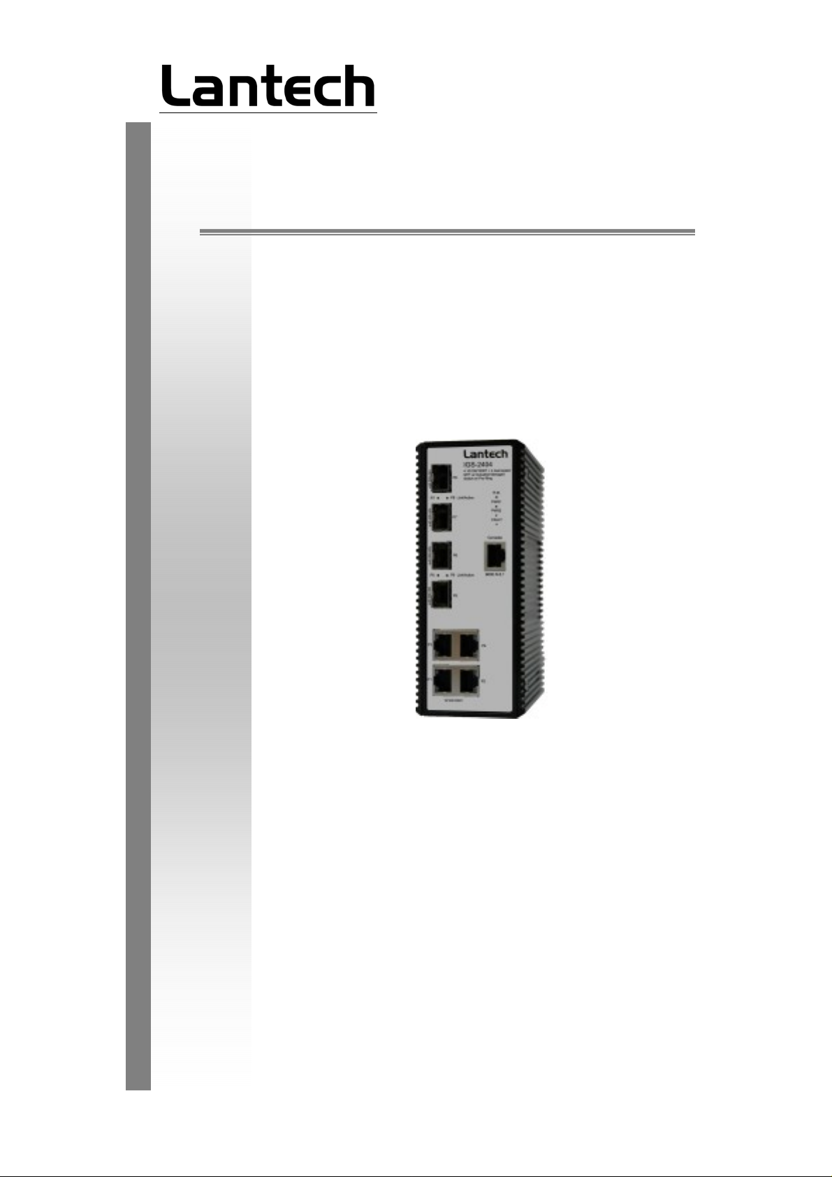
Front Panel
The Front Panel of 4 10/100/1000T + 4 SFP Managed Industrial Switch is shown as
below.
g
Standard Model
7
-E Model
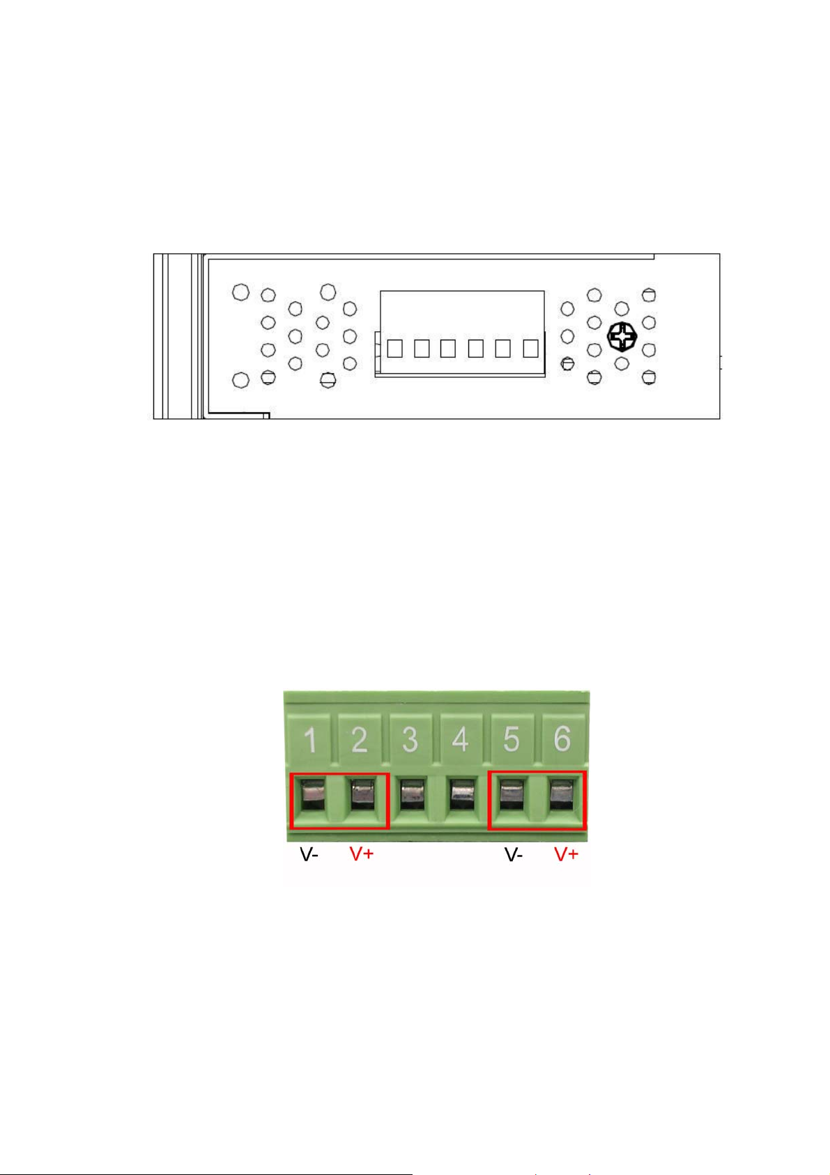
Top View
The top panel of 4 10/100/1000T + 4 SFP Managed Industrial Switch is equipped one
terminal block connector of two DC power inputs.
Top panel of the 4 10/100/1000T + 4 SFP Industrial Switch
Wiring the Power Inputs
Please follow the steps below to insert the power wire.
Insert the positive and negative wires into the V+ and V- contacts on the terminal block
connector.
8
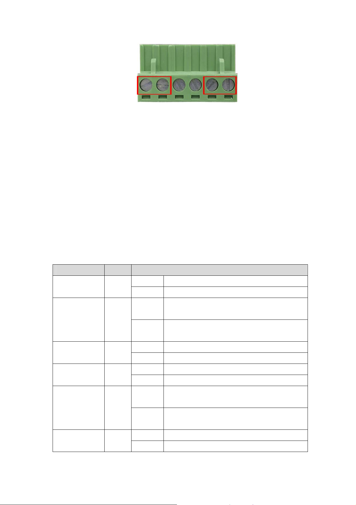
Tighten the wire-clamp screws for preventing the wires from loosing.
Note
The wire gauge for the terminal block should be in the range
between 12~ 24 AWG.
LED Indicators
There are few LEDs display the power status and network status located on the front
panel of 4 10/100/1000T + 4 SFP Industrial Switch, each of them has its own specific
meaning as tabled below.
LED Color Description
PWR Green
R.M. Green
On System power on
Off No power inputs
The industrial switch is the master of the X-ring
On
group
The industrial switch is not the master of the X-ring
Off
group
PWR1 Green
PWR2 Green
Fault Red
Green
(P5 ~ P8)
On Power input 1 is active
Off Power input 1 is inactive
On Power input 2 is active
Off Power input 2 is inactive
On
Off
On SFP port is linking Link/Active
Flashing Data is transmitting or receiving
Power input 1 or 2 is inactive or port link down
(depends on Fault Relay Alarm configuration)
Power input 1 and 2 are both functional, or no power
inputs
9

Off Not connected to network
P1 ~ P4
(Upper LED)
(Lower LED)
Ports
RJ-45 ports (Auto MDI/MDIX): The RJ-45 ports are auto-sensing for 10Base-T,
100Base-TX or 1000Base-T devices connections. Auto MDI/MDIX means that you can
connect to another switch or workstation without changing straight through or
crossover cabling. See figures as below for straight through and crossover cable
schematic.
On Connected to network
Green
Green
LED indicators of 4 10/100/1000T + 4 SFP Managed Industrial Switch
Flashing Networking is active at speed of 100Mbps
Off Not connected to network
On Connected to network at speed of 1000Mbps P1 ~ P4
Off Not connected to network
RJ-45 Pin Assignments
Pin Number Assignment
1 Tx+
2 Tx3 Rx+
6 Rx-
Note “+” and “-” signs represent the polarity of the wires that make up each wire
pair.
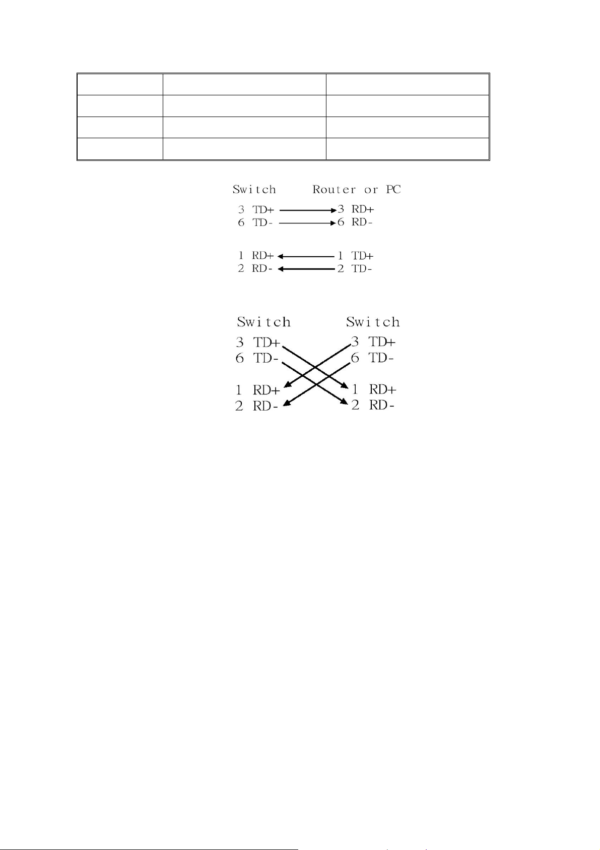
All ports on this industrial switch support automatic MDI/MDI-X operation, you can use
straight-through cables (See Figure below) for all network connections to PCs or
servers, or to other switches or hubs. In straight-through cable, pins 1, 2, 3, and 6, at
one end of the cable, are connected straight through to pins 1, 2, 3 and 6 at the other
end of the cable. The 10BASE-T/100BASE-TX/1000BASE-T MDI and MDI-X port pin
outs are as tabled below.
Pin MDI-X Signal Name MDI Signal Name
10
1 Receive Data plus (RD+) Transmit Data plus (TD+)
2 Receive Data minus (RD-) Transmit Data minus (TD-)
3 Transmit Data plus (TD+) Receive Data plus (RD+)
6 Transmit Data minus (TD-) Receive Data minus (RD-)
Straight Through Cable Schematic
Cabling
Use the four twisted-pair, Category 5e or above cabling for RJ-45 port connection. The
cable between the switch and the link partner (switch, hub, workstation, etc.) must be
less than 100 meters (328 ft.) long.
As for the small form-factor pluggable (SFP), which is a compact optical transceiver
used in optical communications for both telecommunication and data communication
applications.
To connect the transceiver and LC cable, please take the steps shown as follows:
First, insert the transceiver into the SFP module. Notice that the triangle mark is the
bottom of the module.
Cross Over Cable Schematic
11
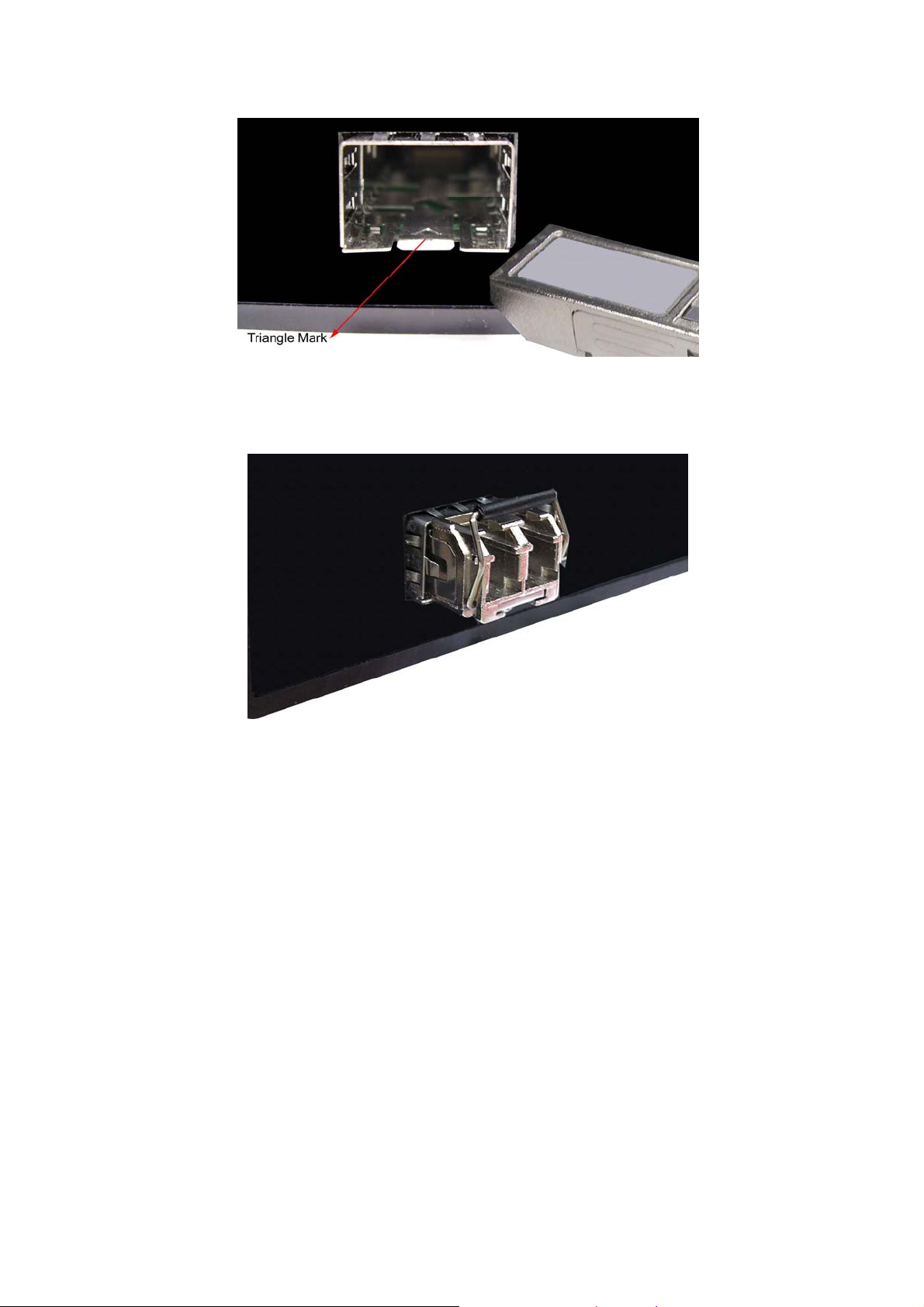
Transceiver to the SFP module
Transceiver Inserted
12
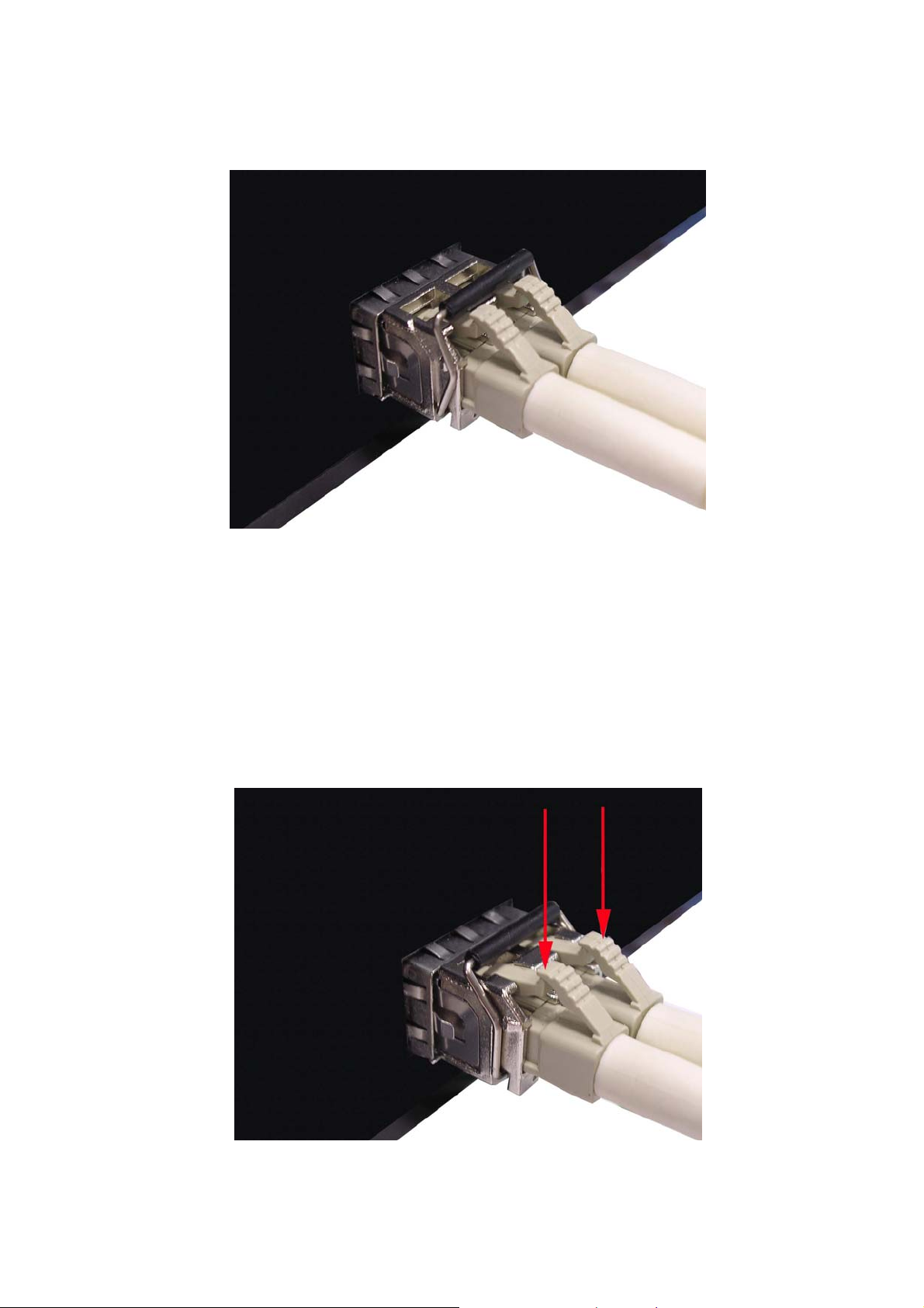
Second, insert the fiber cable of LC connector into the transceiver.
LC connector to the transceiver
To remove the LC connector from the transceiver, please follow the steps shown
below:
First, press the upper side of the LC connector from the transceiver and pull it out to
release.
Remove LC connector
13

Second, push down the metal loop and pull the transceiver out by the plastic part.
Pull out from the SFP module
14
Mounting Installation
DIN-Rail Mounting
The DIN-Rail is screwed on the industrial switch when out of factory. If the DIN-Rail is
not screwed on the industrial switch, please see the following figure to screw the
DIN-Rail on the switch. Follow the below steps to hang the industrial switch.
Step 1: Use the screws to screw on the DIN-Rail on the industrial switch.
Step 2: To remove the DIN-Rail, reverse step 1.
15
1. First, insert the top of DIN-Rail into the track.
2. Then, lightly push the button of DIN-Rail into the track.
3. Check the DIN-Rail is tightly on the track.
4. To remove the industrial switch from the track, reverse the steps above.
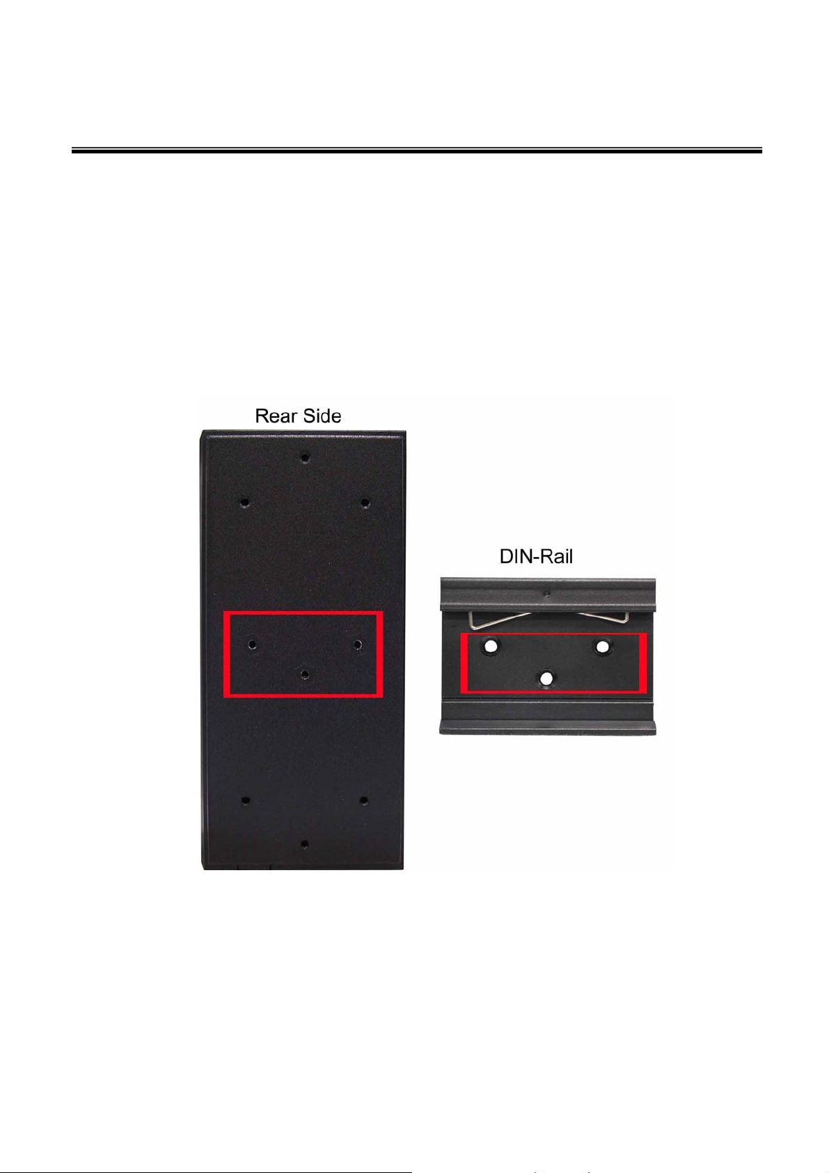
Wall Mount Plate Mounting
Follow the steps as below to mount the industrial switch with wall mount plate.
1. Remove the DIN-Rail from the industrial switch; loose the screws to remove the DIN-Rail.
2. Place the wall mount plate on the rear panel of the industrial switch.
3. Use the screws to screw the wall mount plate on the industrial switch.
16
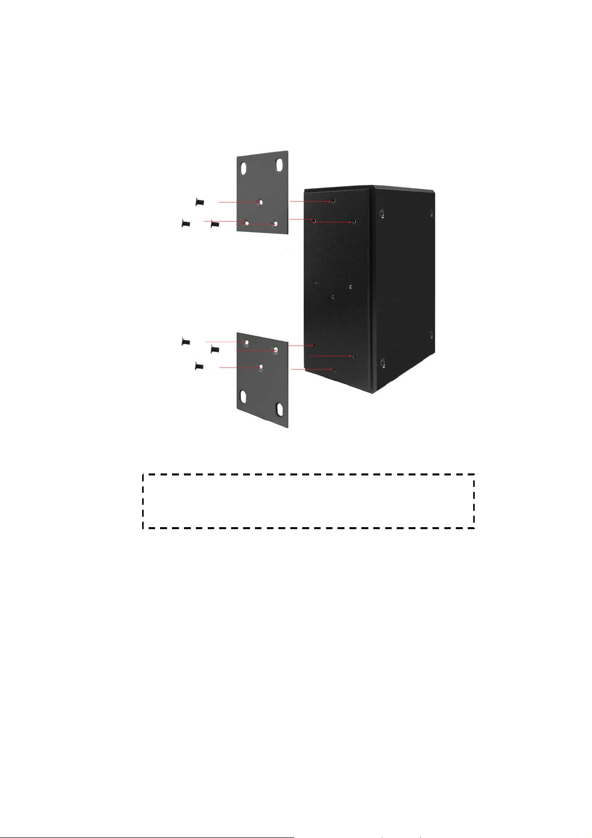
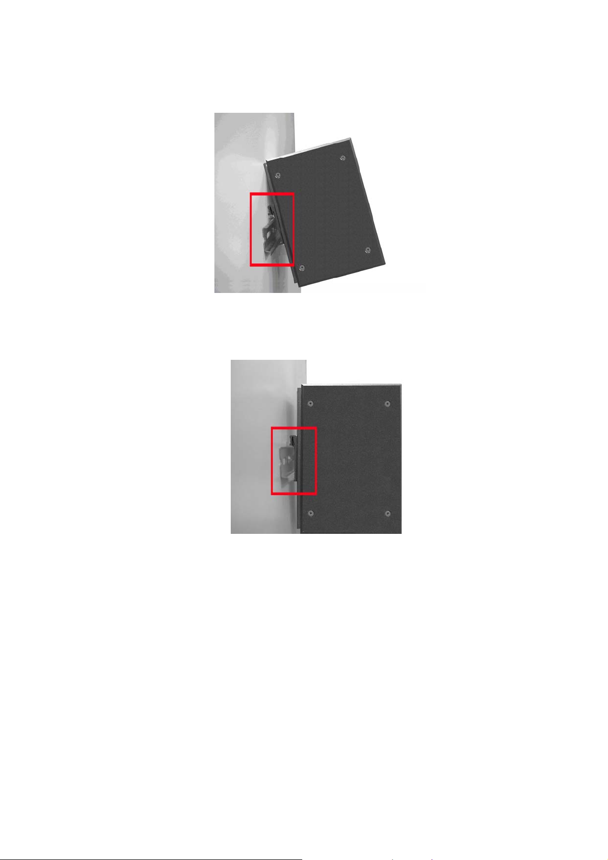
4. Use the hook holes at the corners of the wall mount plate to hang the industrial switch on
the wall.
5. To remove the wall mount plate, reverse steps above.
Use screws to screw the wall mount plate on the rear side
17
Hardware Installation
In this paragraph, we will describe how to install the 4 10/100/1000T + 4 SFP Industrial Switc
and the installation points for the attention.
h
Installat
Unpacked the Industrial switch packing.
1.
2. Check the DIN-Rail is screwed on the Industrial switch. If the DIN-Rail is not screwed on
the Industrial switch. Please refer to DIN-Rail Mounting section for DIN-Rail installation.
If you want to wall mount the Industrial switch, then please refer to Wall Mount Plate
Mounting section for wall mount plate installation.
3. To hang the Industrial switch on the DIN-Rail track or wall, please refer to the Mounting
Installation section.
ion Steps
18

Power on the Industrial switch. How to wire the power; please refer to the Wiring the
4.
Power Inputs section. The power LED on the Industrial switch will light up. Please refer
to the LED Indicators section for meaning of LED lights.
5. Prepare the twisted-pair, straight through Category 5e/above cable for Ethernet
connection and SFP transceiver with LC cable for fiber connection.
6. Insert one side of Category 5e or above cables into the Industrial switch Ethernet port
(RJ-45 port) and another side of category 5e or above cables to the network devices’
Ethernet port (RJ-45 port), ex: switch, PC or Server. The UTP port (RJ-45) LED on the
Industrial switch will light up when the cable connected with the network device. Please
refer to the LED Indicators section for LED light meaning.
Note Be sure the connected network devices support MDI/MDI-X. If it does not
support, then use the crossover category 5e/above cable.
7. As for the SFP (mini-GBIC) port, please refer to the Cabling segment.
8. When all connections are all set and LED lights all show in normal, the installation is
complete.
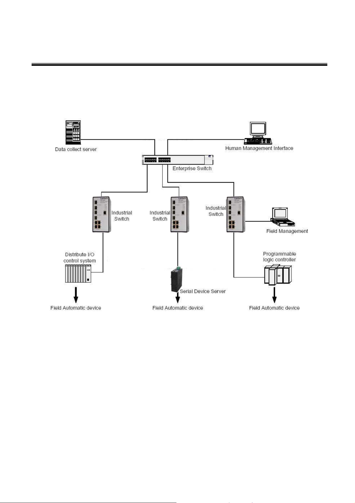
X-Ring Application
The industrial switch supports the X-Ring protocol that can help the net
recover from network connection failure within 10ms or less, and make the network
system more reliable. The X-Ring algorithm is similar to Spanning Tree Protocol (STP)
and Rapid STP (RSTP) algorithm but its recovery time is less than STP/RSTP. The figure
below is a sample of X-Ring application.
work system
19
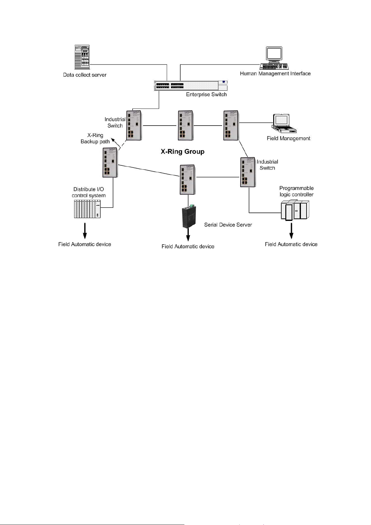
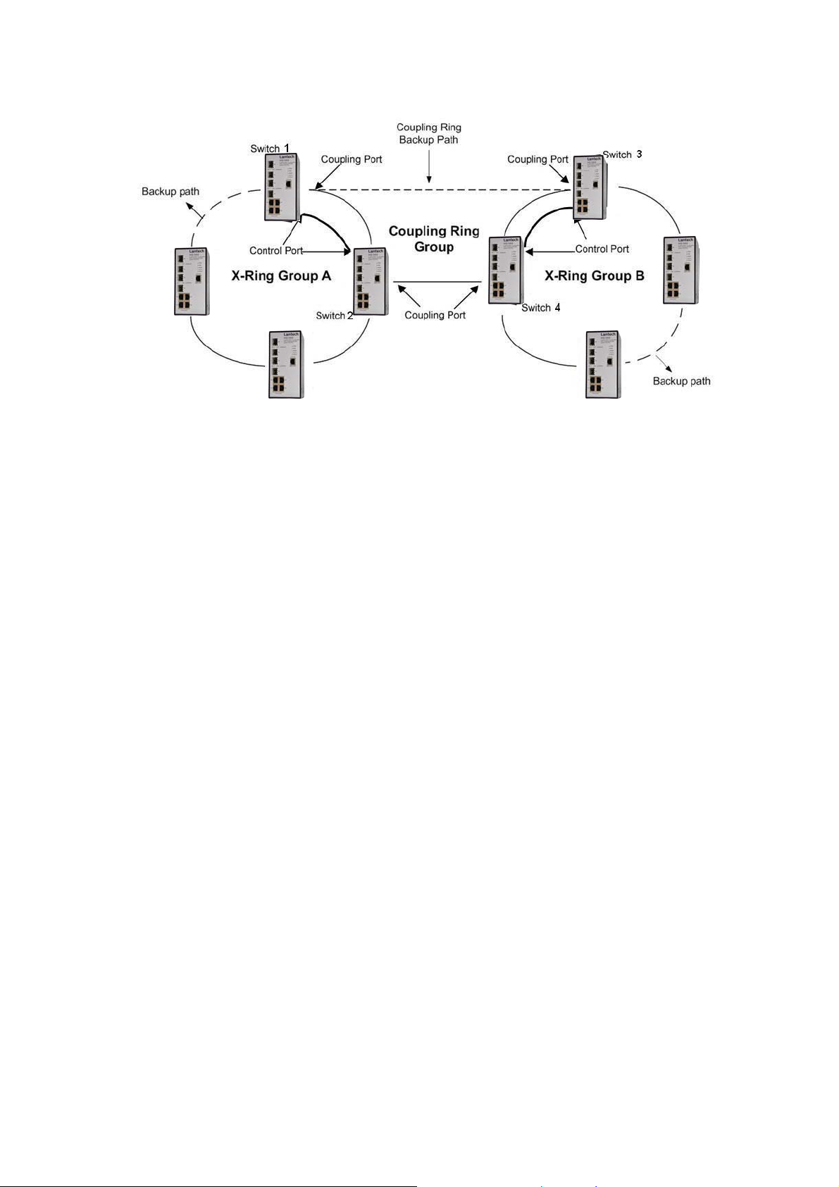
Coupling Ring Application
In the netw
can connect each X-Ring for the redundant backup. It can ensure the transmissions
between two ring groups not to fail. The following figure is a sample of coupling ring
application.
ork, it may have more than one X-Ring group. Using the coupling ring function
20
Dual Homing Application
Dual Homing function is to prevent the connection loss from between X-Ring group and
upper level/core switch. Assign two ports to be the Dual Homing port that is backup port
in the X-Ring group. The Dual Homing function only works when the X-Ring function is
active. Each X-Ring group only has one Dual Homing port.
Note In dual Homing application architecture, the upper level switches need to
enable the Rapid Spanning Tree protocol.
21

22
Console Management
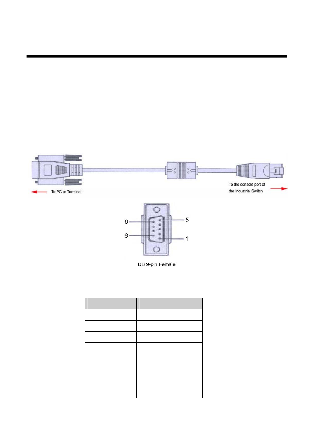
Connecting to the Console Port
The supplied cable which one end is RS-232 connector and the other end is RJ-45
connector. Attach the end of RS-232 connector to PC or terminal and the other end of
RJ-45 connector to the console port of switch. The connected terminal or PC must
support the terminal emulation program.
Pin Assignment
DB9 Connector RJ-45 Connector
NC 1 Orange/White
2 2 Orange
3 3 Green/White
NC 4 Blue
5 5 Blue/White
NC 6 Green
NC 7 Brown/White
NC 8 Brown
23
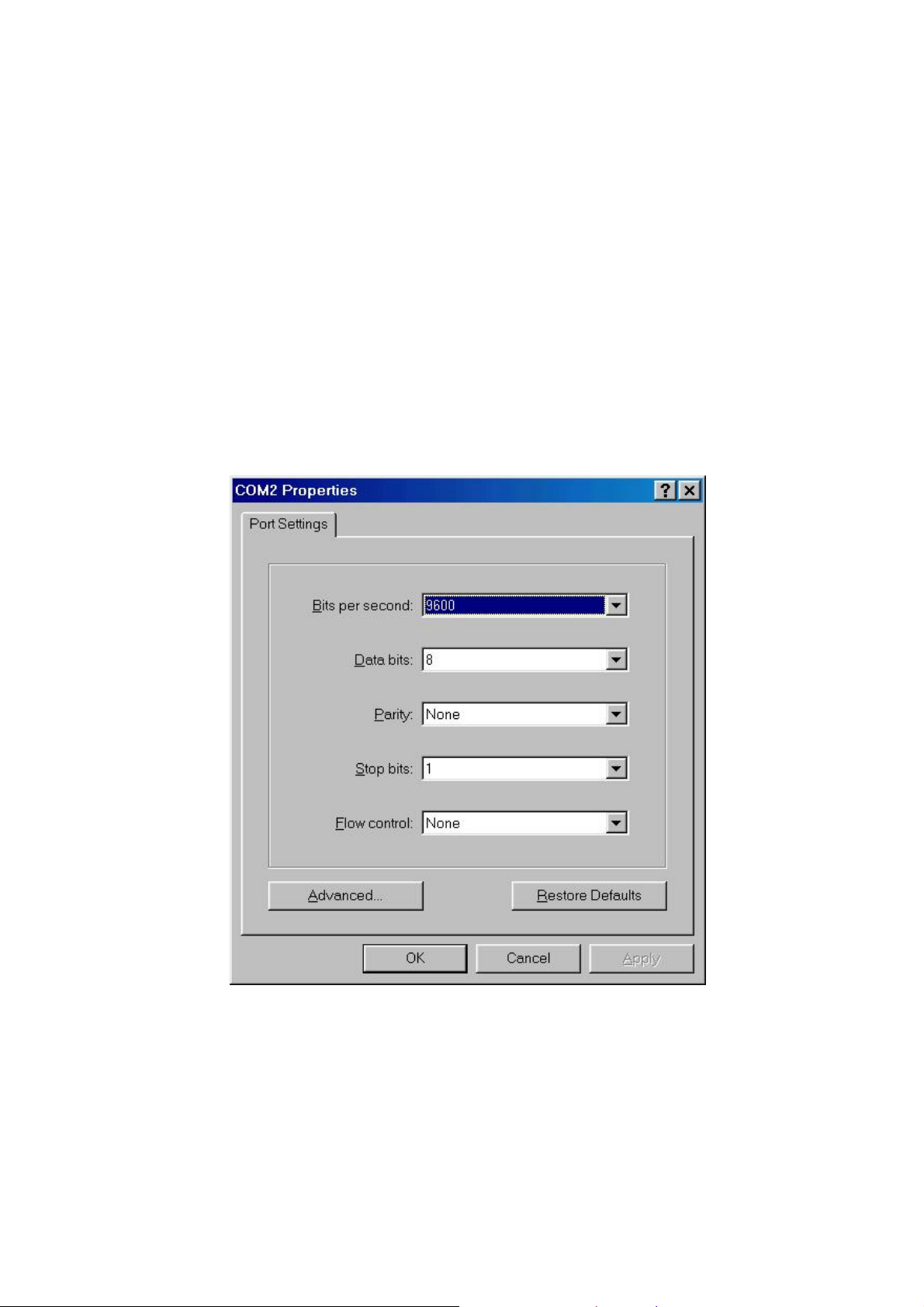
Login in the Console Interface
When the connection between Switch and PC is ready, turn on the PC and run a terminal
emulation program or Hyper Terminal and configure its communication parameters to
match the following default characteristics of the console port:
Baud Rate: 9600 bps
Data Bits: 8
Parity: none
Stop Bit: 1
Flow control: None
The settings of communication parameters
After finishing the parameter settings, click ‘OK’. When the blank screen shows up, press
Enter key to bring out the login prompt. Key in the ‘root’ (default value) for the both User
name and Password (use Enter key to switch), then press Enter key and the Main Menu
of console management appears. Please see below figure for login screen.
24
 Loading...