

Lantech
IES-0008-M12
8 10/100TX IP41 rated Industrial Switch
w/M12 connectors
User Manual

Content
Overview ............................................................ 1
Introduction .............................................................. 1
Features ................................................................... 2
Technical Specification ............................................ 3
Packing List .............................................................. 5
Safety Precaution ..................................................... 5
Hardware Description ......................................... 6
Physical Dimensions ................................................ 6
Front Panel ............................................................... 7
LED Indicators .......................................................... 8
Fast Ethernet Ports .................................................. 9
Pinouts of the Power Connector ............................ 10
Installation ........................................................ 11
Wall Mounting ........................................................ 11
DIN-Rail Mounting .................................................. 12
Grounding the Ethernet Switch .............................. 13
Troubleshooting ............................................... 14

1
Overview
Introduction
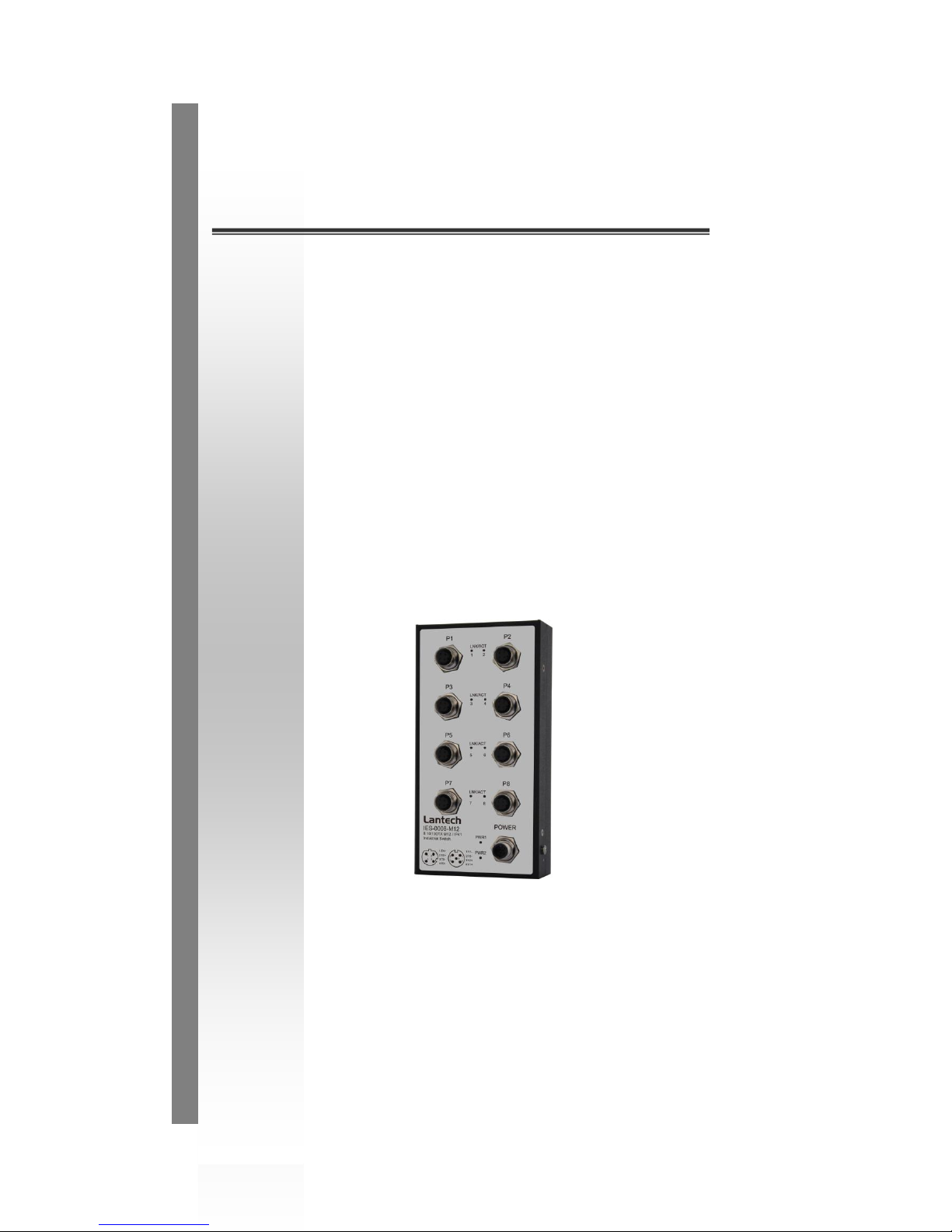
The 8 10/100TX IP41 rated Industrial Switch w/M12 connectors is a
rugged device to be deployed in various environments. The Ethernet
switch conforms to EN50155, EN50121-3-2, EN50121-4 railway
applications standards.
Heavy Duty
Designed with circular M12 connectors and constructed with metallic
housing, the Ethernet switch provides the rugged Fast Ethernet
interface to withstand vibration and shock.
Dual Power Inputs
The redundant power input design for the Ethernet switch gives a
backup power solution. With both the power inputs supplied, if either
one fails the other one will be activated to keep the systems operating
continually.
Flexible Mounting
The Ethernet switch is compact and can be mounted on the wall, and it
is suitable for any space-constrained environment.
Bypass Function
The equipment is designed with the function known as Bypass. When
the power failure occurs, a shorted circuit between two Ethernet ports
(P1 and P2) is formed to have the equipment being a bypassed device
to prevent the network from disconnecting.

2
Features
Back-plane (switching fabric) : 1.6Gbps
M12 connectors and IP41 metal housing
Wide range redundant power design
Wide operating temperature (-40~75ºC)
EN50155/50121-3-2/50121-4
Auto Bypass between Port 1 and Port 2

3
Technical Specification
Communications
Standard
IEEE 802.3 10Base-T
IEEE 802.3u 100Base-TX
IEEE 802.3x Flow control and back pressure
LAN
10/100Base-TX
Transmission Speed
Up to 100 Mbps
Switch Architecture
Back-plane: 1.6Gbps
Packet Buffer
448Kbits
MAC Address Table
2K-entry
Interface
Connectors
8 x M12, 4-pole D-coded, female (10/100TX)
with the bypass function (P1 and P2)
1 x M12, 5-pole A-coded, male (Power)
LED Indicators
System: PWR1, PWR2
10/100Base-TX port: LNK/ACT
Power
Power Consumption
3.36 Watts max. @ 48 VDC
Power Input
12 ~ 48 VDC
Mechanism
Dimensions (WxHxD)
92 x 180 x 42 mm
Enclosure
IP41 protection, metal housing
Mounting
DIN-rail, Wall
Environment
Operating Temperature
-40 ~ 75oC (-40 ~ 167oF)
Operating Humidity
5% ~ 95% (non-condensing)
Storage Temperature
-40 ~ 85oC (-40 ~ 185oF)

4
Storage Humidity
5% ~ 95% (non-condensing)
MTBF
391, 306 hours
Certifications
Safety
UL, cUL 60950
EMC
CE, FCC Class A
CE EN61000-4-2 (ESD)
CE EN61000-4-3 (RS)
CE EN61000-4-4 (EFT)
CE EN61000-4-5 (Surge)
CE EN61000-4-6 (CS)
CE EN61000-4-8 (Magnetic Field)
CE EN61000-6-2
CE EN61000-6-4
Railway Traffic
EN50155, EN50121-3-2, EN50121-4
Free Fall
IEC60068-2-32
Shock
IEC61373
Vibration
IEC61373
5
Packing List
1 x 8 10/100TX IP41 rated Industrial Switch w/M12 connectors
2 x Wall-mount plates with screws
1 x DIN-rail clip with screws
1 x User Manual (CD-ROM)
Compare the contents of the Ethernet switch with the standard checklist
above. If any item is damaged or missing, please contact the local dealer
for service.
Safety Precaution
IF DC voltage is supplied by an external circuit, please use a
protection device on the power supply input.
ATTENTION
6
Hardware Description
This section is intended to introduce the Ethernet switch’s dimensions, definitions of
LED indicators, and connector pinouts.
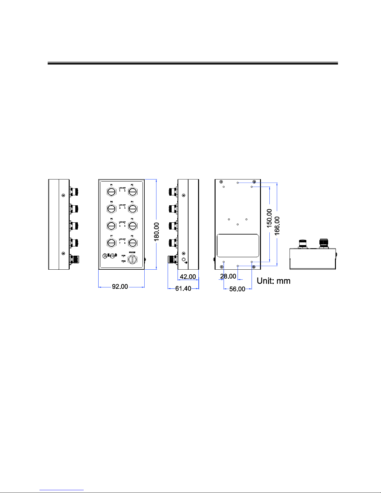
Physical Dimensions
The figure below illustrates the dimensions for the Ethernet Switch.
Mechanical Dimensions

7
Front Panel
The figure shown below is the Front Panel of the Ethernet switch.
Front Panel
8
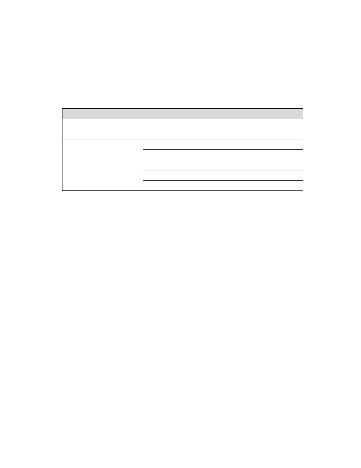
LED Indicators
LED indicators located on the front panel display the status of system power,
networking and power feeding over Ethernet of the Ethernet switch. Please refer to the
following table for further details.
LED
Color
Description
PWR1
Green
On
Power input 1 is active
Off
Power input 1 is inactive
PWR2
Green
On
Power input 2 is active
Off
Power input 2 is inactive
LNK/ACT
Green
On
Connected to network
Blinks
Data is transmitting/receiving
Off
Not connected to network
Definition of LED indicators
9
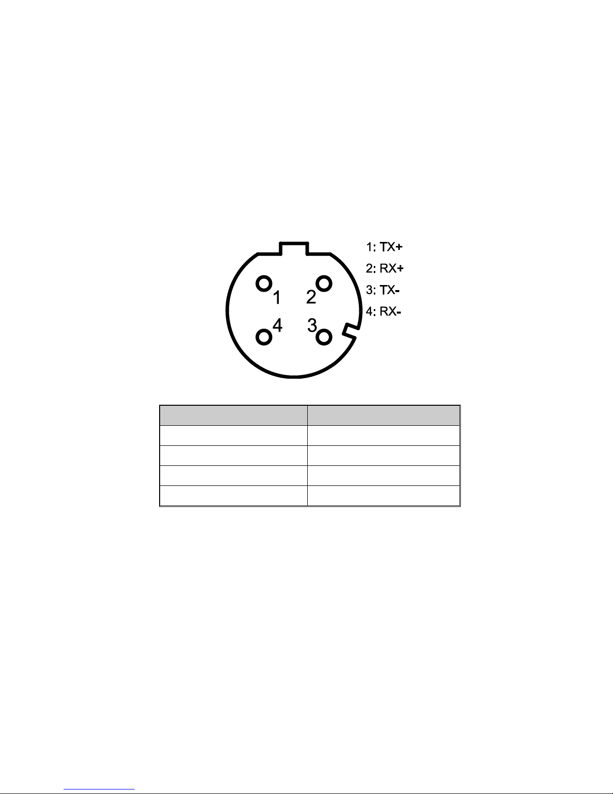
Fast Ethernet Ports
Prepare the M12, 4-pole D-Coded Fast Ethernet Port mating cable for Ethernet
connection. The M-12 D-coded Fast Ethernet ports are auto-sensing for 10Base-T or
100Base-TX devices connections. Auto MDI/MDIX means that you can connect to
another switch or workstation without changing straight through or crossover cabling.
M12 D-coded Connector Pin Assignments
Pin Number
Assignments
1
Tx+
2
RX+
3
TX-
4
Rx-
Note
“+” and “-” signs represent the polarity of the wires that make up each wire
pair.
10
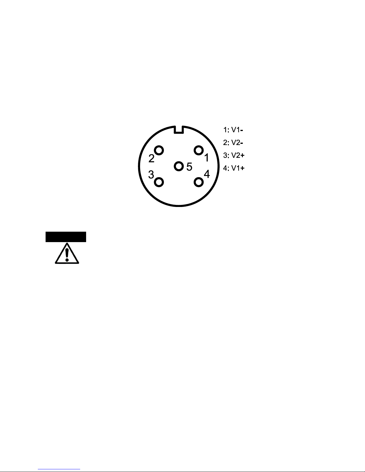
Pinouts of the Power Connector
Prepare the M12, 5-pole A-Coded cable for Ethernet connection. Connect the positive
and negative wires to PWR1 (V1+, V1-) and PWR2 (V2+, V2-) as the power pin
assignments shown below.
Power1 & Power2 Contacts of the M12 Connector
Only trained and qualified personnel should be allowed to install or
replace this equipment.
Warning
11
Installation
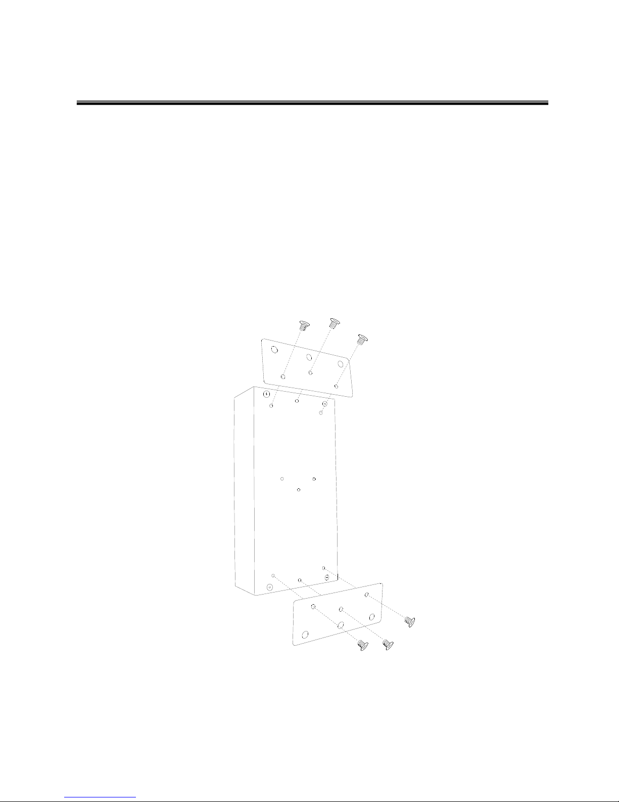
Wall Mounting
To hang the Ethernet switch on the wall, please follow the steps below.
1. Prepare the two wall-mount plates and six screws included.
2. Align the screw holes between the wall-mount plates and the unit as the figure
illustrated.
3. Secure the plates to the unit with the accompanying screws.
4. Having secured the plates to the unit, you can hang the Ethernet switch on something
like nails sticking out from the wall.

12
DIN-Rail Mounting
To mount the Ethernet switch to a standards DIN rail, please follow the steps below.
1. Prepare the DIN-rail clip and three screws included.
2. Align the screw holes between the clip and the unit as the figure illustrated.
3. Secure the DIN-rail clip to the unit with the accompanying screws.
4. After you have secured the DIN-rail clip to the unit, position the clip side of the
Ethernet switch directly in front of a standard DIN rail. Make sure the top of the clip
hooks over the top of the DIN rail.
13
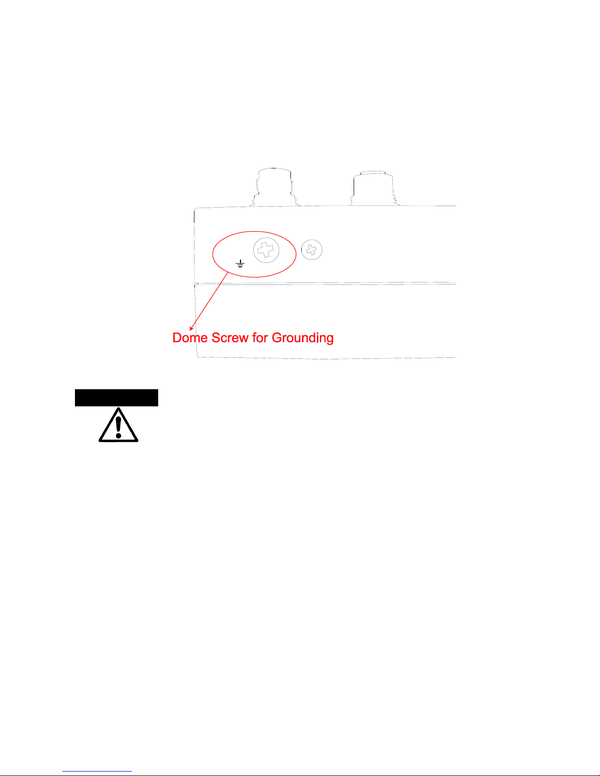
Grounding the Ethernet Switch
Follow the instructions below to attach the Ethernet switch to ground.
When installing the Ethernet switch, the ground connection must
always be made first and disconnected last.
1. Locate and remove the dome screw which has a ground symbol beside it.
2. Attach the ground wire to the screw hole with the dome screw.
ATTENTION

14
Troubleshooting
Verify that you are using the correct power cord/adapter. Don’t use the power adapter
with DC output higher than the rated voltage of the equipment. Or the equipment will be
damaged.
Select proper cables to construct your network. Please check that you are using the right
cables.
Diagnosing LED Indicators: the equipment can be easily monitored through panel
indicators, which describes common problems you may encounter and where you can
find possible solutions to assist in identifying problems.
If the power indicator does not light up when the power cord is plugged in, you may have
a problem with power cord. Then check for loose power connections, power losses or
surges at power outlet. If you still cannot resolve the problem, contact your local dealer
for assistance.
If the LED indicators are normal while the corresponding cables are connected correctly
but the networking is still inactive, please check your system’s Ethernet devices’
configuration or status.
 Loading...